
Helmholtz Resonance Frequency of the Synthetic Jet Actuator


Abstract
:1. Introduction
2. Materials and Methods
3. Results
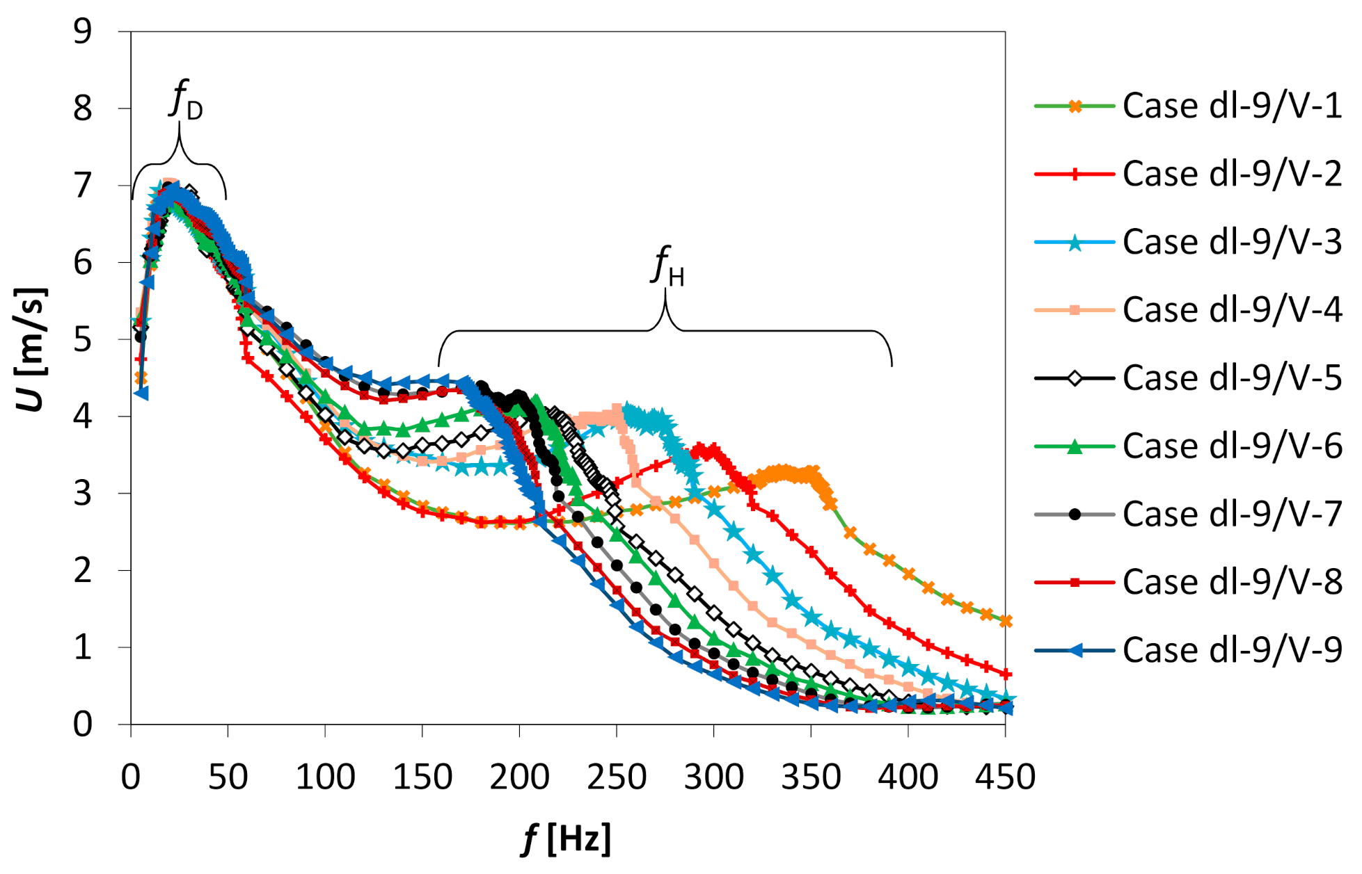
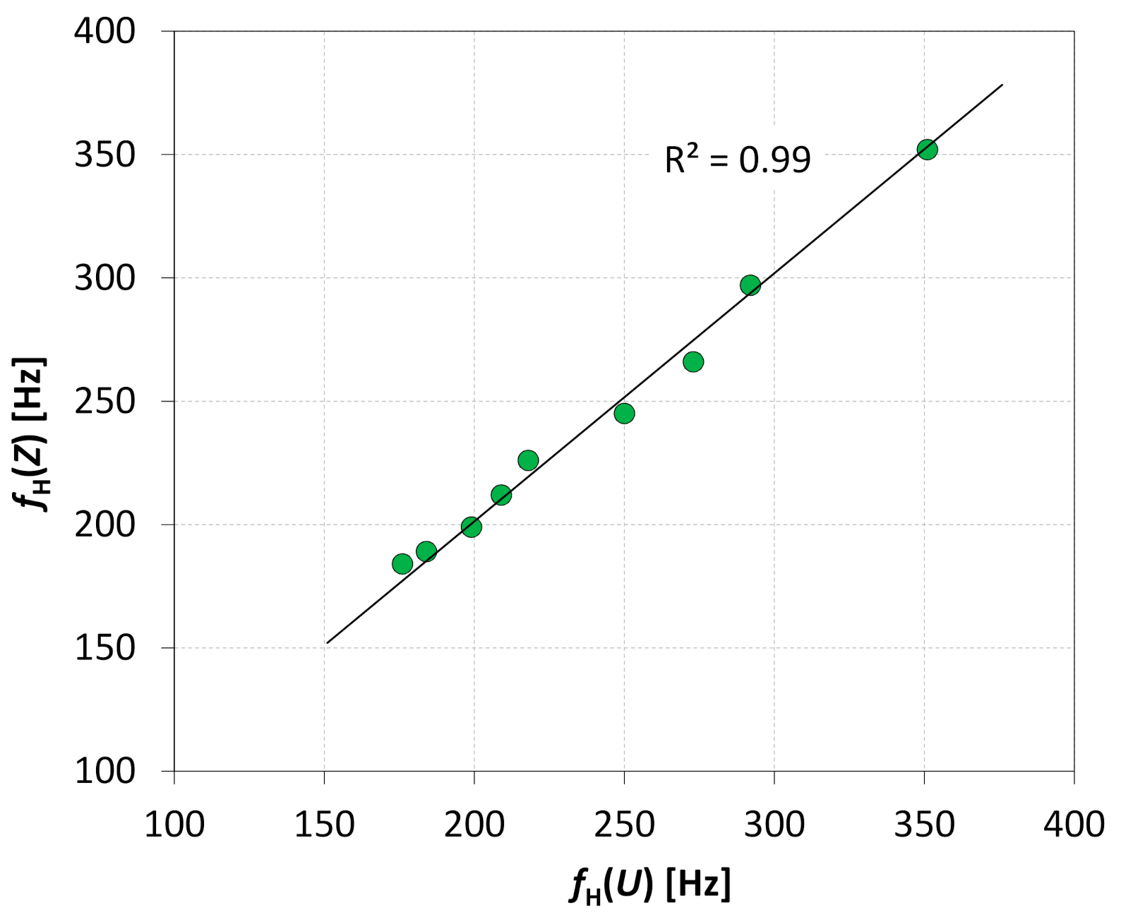
3.1. Identification of Resonance Frequencies
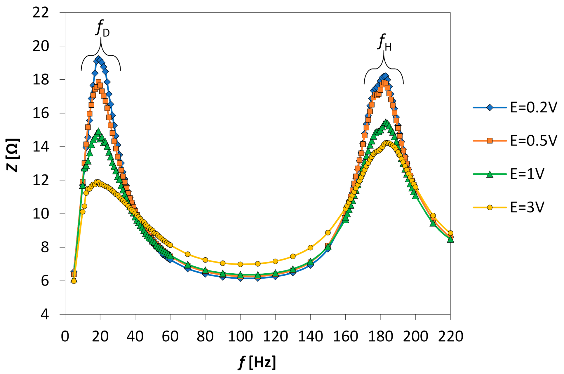
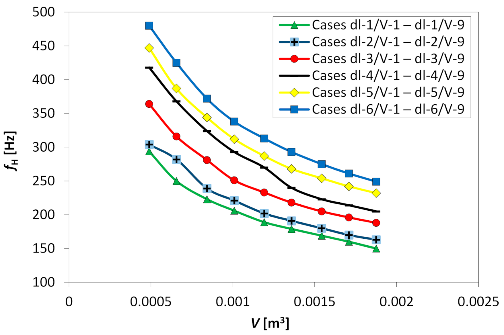
3.2. Effects of The Supply Voltage and SJ Actuator Geometrical Parameters on the Helmholtz Resonance Frequency
4. Discussion
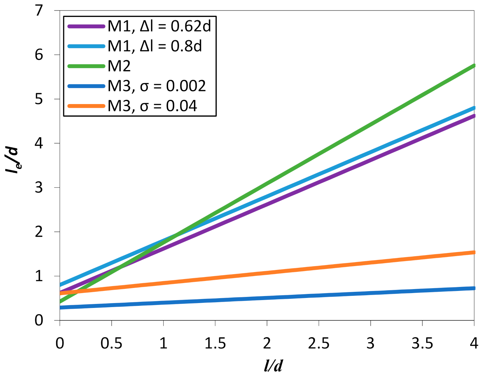
4.1. Helmholtz Resonance Frequency Model
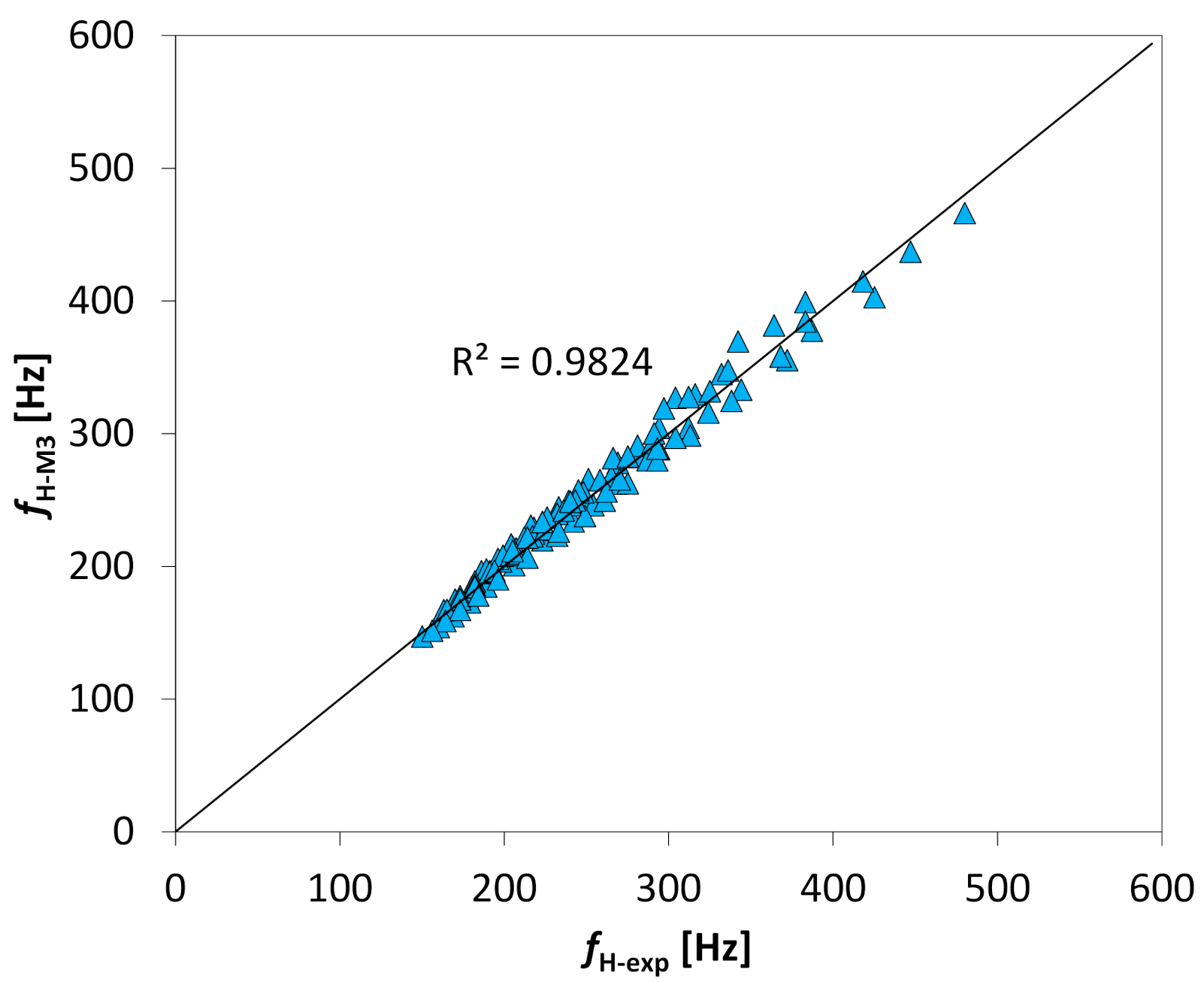
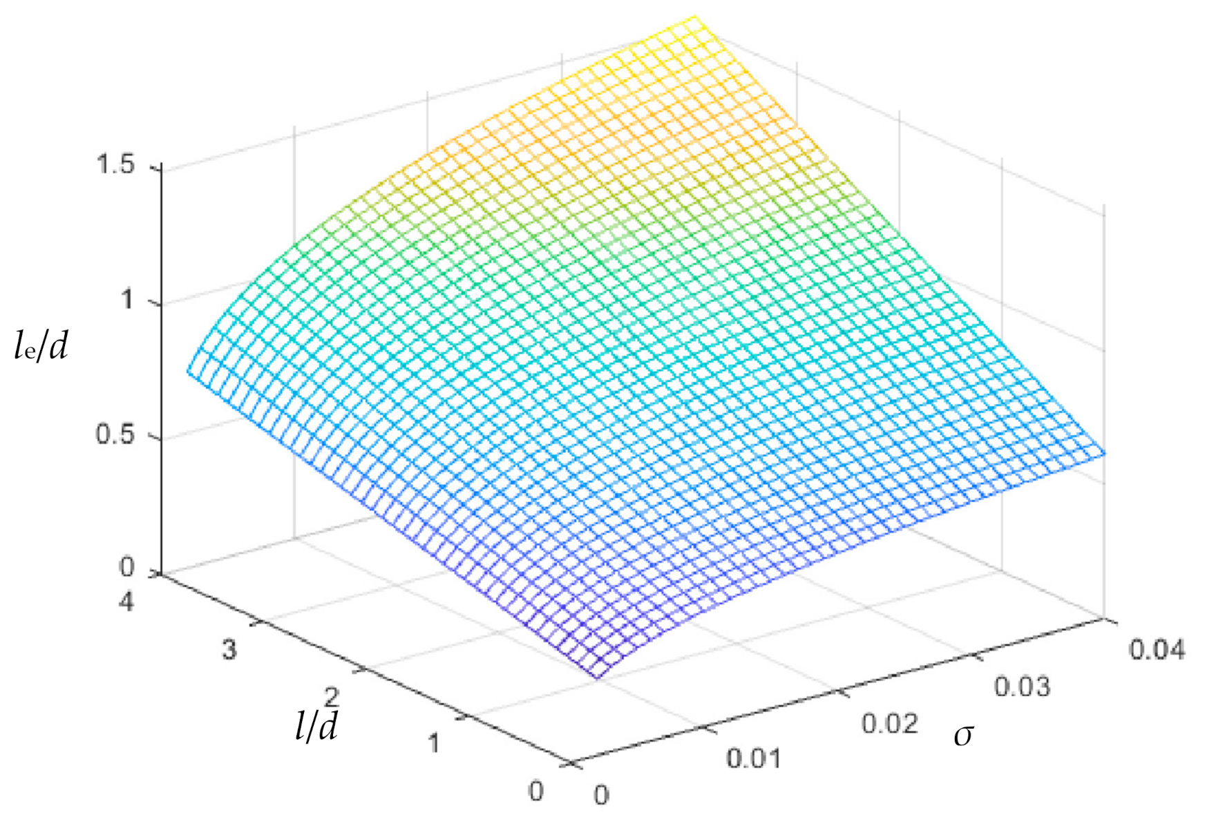
4.2. The Improved Version of the Model
4.3. Coupling Ratio in the Analysis of the Model of the Helmholtz Resonance Frequency of an SJ Actuator
5. Conclusions
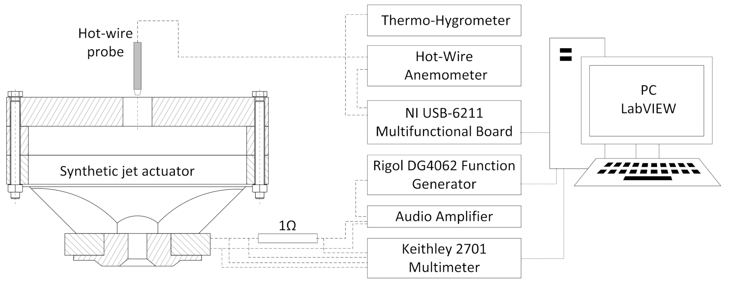
- The Helmholtz resonance frequency can be determined from measurements of electrical parameters or measurements of the air velocity. However, due to the higher precision and greater repeatability of electrical measurements in relation to air velocity measurements with the use of constant temperature anemometry, the first method appears to be more appropriate.
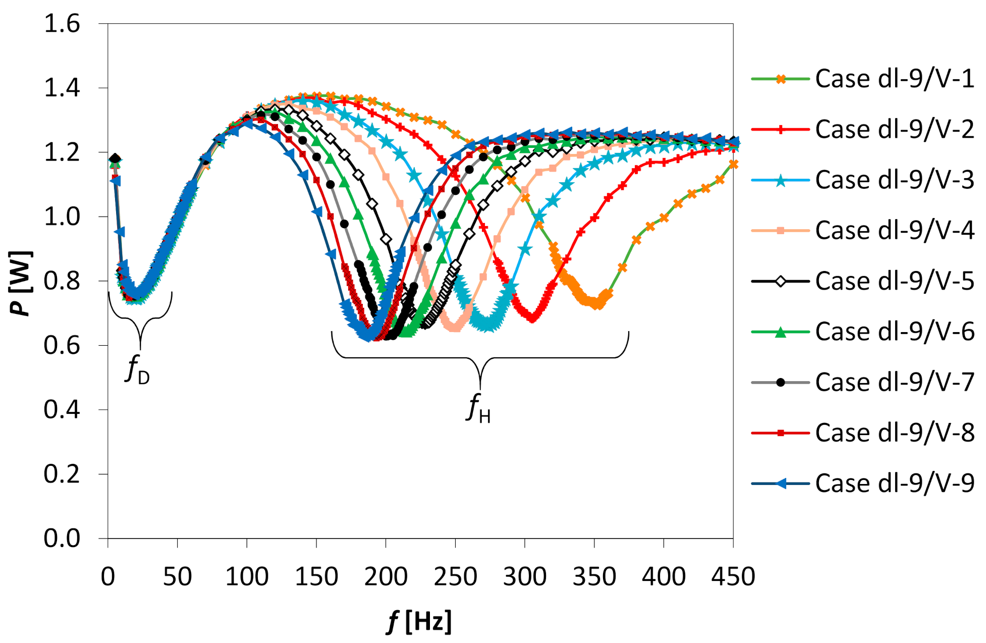
- The resonance frequencies do not depend on the actuator supply voltage in the considered range of effective voltages.
- There is a decrease in fH with an increase in V, in the cases of constant d or l values. In addition, the Helmholtz resonance frequency increases as the orifice diameter increases at a constant value of the cavity volume and decreases as the orifice length increases.
- The additive length ∆l in the effective orifice length le is a function not only of the orifice diameter, but also of the orifice length l and the surface ratio σ.
- The obtained investigation results enabled the determination of an improved model for the Helmholtz resonance frequency of a synthetic jet actuator.
- The model obtained is valid in the case of SJ actuators characterized by large values of the coupling ratio.
Author Contributions
Funding
Institutional Review Board Statement
Informed Consent Statement
Data Availability Statement
Conflicts of Interest
Nomenclature
| A | orifice surface area [m2] |
| AD | diaphragm wall area [m2] |
| CR | coupling ratio [-] |
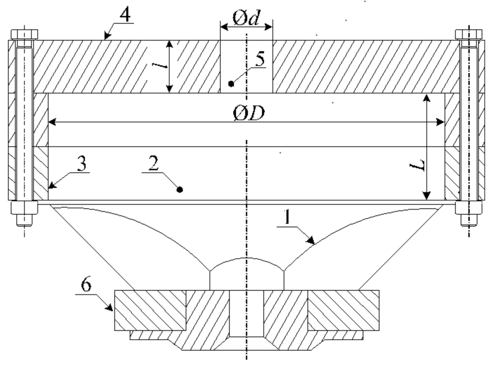
| D | cavity internal diameter [mm] |
| d | orifice diameter [mm] |
| E | effective voltage [V] |
| f | symbol of a function |
| f | excitation frequency [Hz] |
| fD | diaphragm resonance frequency [Hz] |
| fH | Helmholtz resonance frequency [Hz] |
| kD | diaphragm equivalent stiffness [N/m] |
| I | effective electric current [A] |
| L | cavity length [mm] |
| l | orifice length [mm] |
| ∆l | additive length [mm] |
| le | effective length [mm] |
| m | effective mass of the air at the orifice [kg] |
| mD | mass of the diaphragm [kg] |
| P | apparent power [W] |
| pa | ambient pressure [Pa] |
| T | oscillation period [s] |
| U | characteristic velocity [m/s] |
| u | instantaneous velocity [m/s] |
| V | cavity volume [m3] |
| Z | impedance [Ω] |
| Greek Symbols | |
| κ | specific heat ratio [-] |
| ρ | air density [kg/m3] |
| σ | surfaces ratio d2/D2 [-] |
| υ | speed of sound [m/s] |
| τ | time [s] |
References
- Arshad, A.; Jabbal, M.; Yan, Y. Synthetic jet actuators for heat transfer enhancement—A critical review. Int. J. Heat Mass Transf. 2020, 146, 118815. [Google Scholar] [CrossRef]
- Krishan, G.; Aw, K.C.; Sharma, R.N. Synthetic jet impingement heat transfer enhancement—A review. Appl. Therm. Eng. 2019, 149, 1305–1323. [Google Scholar] [CrossRef]
- Smyk, E.; Gil, P.; Gałek, R.; Przeszłowski, Ł. Acoustic and flow aspects of novel synthetic jet actuator. Actuators 2020, 9, 100. [Google Scholar] [CrossRef]
- Smyk, E.; Wilk, J.; Markowicz, M. Synthetic Jet Actuators with the Same Cross-Sectional Area Orifices-Flow and Acoustic Aspects. Appl. Sci. 2021, 11, 4600. [Google Scholar] [CrossRef]
- James, R.D.; Jacobs, J.W.; Glezer, A. A round turbulent jet produced by an oscillating diaphragm. Phys. Fluids 1996, 8, 2484–2495. [Google Scholar] [CrossRef]
- Kral, L.D.; Donovan, J.F.; Cain, A.B.; Cary, A.W. Numerical simulation of synthetic jet actuators. In Proceedings of the 4th Shear Flow Control Conference, Snowmass Village, CO, USA, 29 June–2 July 1997. [Google Scholar]
- Smith, B.L.; Glezer, A. The formation and evolution of synthetic jets. Phys. Fluids 1998, 10, 2281–2297. [Google Scholar] [CrossRef]
- Guy, Y.; McLaughlin, T.; Morrow, J. Velocity measurements in a synthetic jet. In Proceedings of the 39th Aerospace Sciences Meeting and Exhibit, Reno, NV, USA, 8–11 January 2001. [Google Scholar] [CrossRef]
- Guy, Y.; McLaughlin, T.; Albertson, J.A. Effect of geometric parameters on the velocity output of a synthetic jet actuator. In Proceedings of the 40th AIAA Aerospace Sciences Meeting & Exhibit, Reno, NV, USA, 14–17 January 2002. [Google Scholar] [CrossRef]
- Gil, P.; Smyk, E. Synthetic jet actuator efficiency based on the reaction force measurement. Sens. Actuators A Phys. 2019, 295, 405–413. [Google Scholar] [CrossRef]
- Chaudhari, M.; Verma, G.; Puranik, B.; Agrawal, A. Frequency response of a synthetic jet cavity. Exp. Therm. Fluid Sci. 2009, 33, 439–448. [Google Scholar] [CrossRef]
- Gil, P.; Strzelczyk, P. Performance and efficiency of loudspeaker driven synthetic jet actuator. Exp. Therm. Fluid Sci. 2016, 76, 163–174. [Google Scholar] [CrossRef]
- Kordík, J.; Trávníček, Z. Optimal diameter of nozzles of synthetic jet actuators based on electrodynamic transducers. Exp. Therm. Fluid Sci. 2017, 86, 281–294. [Google Scholar] [CrossRef]
- Gallas, Q.; Mathew, J.; Kaysap, A.; Holman, R.; Nishida, T.; Carrol, B.; Sheplak, M.; Cattafesta, L. Lumped Element Modeling of Piezoelectric-Driven Synthetic Jet Actuators. In Proceedings of the 40th AIAA Aerospace Sciences Meeting & Exhibit, Reno, NV, USA, 14–17 January 2002. [Google Scholar] [CrossRef]
- Gallas, Q.; Holman, R.; Nishida, T.; Carrol, B.; Sheplak, M.; Cattafesta, L. Lumped Element Modeling of Piezoelectric-Driven Synthetic Jet Actuators. AIAA J. 2003, 41, 240–247. [Google Scholar] [CrossRef] [Green Version]
- Gallas, Q. Modeling and development of synthetic jet actuators in flow separation control application. Solid Mech. Its Appl. 2008, 7, 361–364. [Google Scholar] [CrossRef]
- Sharma, R.N. Some insights into synthetic jet actuation from analytical modelling. In Proceedings of the 16th Australasian Fluid Mechanics Conference, Brisbane, Australia, 3–7 December 2007. [Google Scholar]
- Sharma, R.N. Fluid-dynamics-based analytical model for synthetic jet actuation. AIAA J. 2007, 45, 1841–1847. [Google Scholar] [CrossRef]
- Gil, P.; Wilk, J.; Smusz, R.; Gałek, R. Centerline heat transfer coefficient distributions of synthetic jets impingement cooling. Int. J. Heat Mass Transf. 2020, 160. [Google Scholar] [CrossRef]
- Greco, C.S.; Paolillo, G.; Ianiro, A.; Cardone, G.; de Luca, L. Effects of the stroke length and nozzle-to-plate distance on synthetic jet impingement heat transfer. Int. J. Heat Mass Transf. 2018, 117, 1019–1031. [Google Scholar] [CrossRef]
- Tang, H.; Zhong, S. Lumped element modelling of synthetic jet actuators. Aerosp. Sci. Technol. 2009, 13, 331–339. [Google Scholar] [CrossRef]
- Persoons, T. General reduced-order model to design and operate synthetic jet actuators. AIAA J. 2012, 50, 916–927. [Google Scholar] [CrossRef] [Green Version]
- De Luca, L.; Girfoglio, M.; Coppola, G. Modeling and experimental validation of the frequency response of synthetic jet actuators. AIAA J. 2014, 52, 1733–1748. [Google Scholar] [CrossRef]
- Gomes, L.D.; Crowther, W.J.; Wood, N.J. Towards a practical piezoceramic diaphragm based synthetic jet actuator for high subsonic applications-Effect of chamber and orifice depth on actuator peak velocity. In Proceedings of the 3rd AIAA Flow Control Conference, San Francisco, CA, USA, 5–8 June 2006. [Google Scholar]
- Chiatto, M.; Capuano, F.; Coppola, G.; De Luca, L. LEM characterization of synthetic jet actuators driven by piezoelectric element: A review. Sensors 2017, 17, 1216. [Google Scholar] [CrossRef] [PubMed] [Green Version]
- Persoons, T.; Cressall, R.; Alimohammadi, S. Validating a reduced-order model for synthetic jet actuators using CFD and experimental data. Actuators 2018, 7, 67. [Google Scholar] [CrossRef] [Green Version]
- Rossing, T.D. Springer Handbook of Acoustics; Springer Science+Bussiness Media: New York, NY, USA, 2007. [Google Scholar]


| Case | Cavity Length, L [mm] | Cavity Internal Diameter, D [mm] | Cavity Volume, V [cm3] | L/D [-] |
|---|---|---|---|---|
| V-1 | 19.97 | 149.84 | 489.3 | 0.13 |
| V-2 | 29.42 | 149.83 | 655.9 | 0.20 |
| V-3 | 39.95 | 149.89 | 842.0 | 0.27 |
| V-4 | 49.40 | 149.87 | 1009.0 | 0.33 |
| V-5 | 59.82 | 149.80 | 1191.0 | 0.40 |
| V-6 | 69.27 | 149.80 | 1358.0 | 0.46 |
| V-7 | 79.72 | 149.80 | 1542.0 | 0.53 |
| V-8 | 89.17 | 149.80 | 1709.0 | 0.60 |
| V-9 | 98.60 | 149.81 | 1875.0 | 0.66 |
| Case | Orifice Diameter, d [mm] | Orifice Length, l [mm] | l/d [-] |
|---|---|---|---|
| dl-1 | 6.20 | 4.78 | 0.77 |
| dl-2 | 9.12 | 4.81 | 0.53 |
| dl-3 | 15.03 | 4.84 | 0.32 |
| dl-4 | 19.95 | 4.80 | 0.24 |
| dl-5 | 23.95 | 4.79 | 0.20 |
| dl-6 | 30.01 | 4.79 | 0.16 |
| dl-7 | 19.99 | 9.47 | 0.47 |
| dl-8 | 19.97 | 14.27 | 0.71 |
| dl-9 | 19.97 | 19.80 | 0.99 |
| dl-10 | 19.98 | 29.27 | 1.46 |
| dl-11 | 19.99 | 39.78 | 1.99 |
| dl-12 | 19.99 | 59.83 | 2.99 |
| Model | Δl/d |
|---|---|
| M1 | 0.62 |
| M1 | 0.8 |
| M2 | l/(3d) + 4/(3π) |
Publisher’s Note: MDPI stays neutral with regard to jurisdictional claims in published maps and institutional affiliations. |
© 2021 by the authors. Licensee MDPI, Basel, Switzerland. This article is an open access article distributed under the terms and conditions of the Creative Commons Attribution (CC BY) license (https://creativecommons.org/licenses/by/4.0/).
Share and Cite
Gil, P.; Wilk, J.; Korzeniowski, M. Helmholtz Resonance Frequency of the Synthetic Jet Actuator. Appl. Sci. 2021, 11, 5666. https://doi.org/10.3390/app11125666
Gil P, Wilk J, Korzeniowski M. Helmholtz Resonance Frequency of the Synthetic Jet Actuator. Applied Sciences. 2021; 11(12):5666. https://doi.org/10.3390/app11125666
Chicago/Turabian StyleGil, Paweł, Joanna Wilk, and Michał Korzeniowski. 2021. "Helmholtz Resonance Frequency of the Synthetic Jet Actuator" Applied Sciences 11, no. 12: 5666. https://doi.org/10.3390/app11125666