Article

Study on the Mechanical Characteristics of the Sleeper Slab Track on a Long-Span Steel Truss Bridge

1
School of Civil Engineering, Central South University, Changsha 410075, China
2
Key Laboratory of Ministry of Education for Heavy Haul Railway Engineering Structure, Central South University, Changsha 410075, China
3
China Railway Siyuan Survey and Design Group Co., Ltd., Wuhan 430063, China
*
Author to whom correspondence should be addressed.
Appl. Sci. 2021, 11(11), 5273; https://doi.org/10.3390/app11115273
Submission received: 8 April 2021 / Revised: 30 May 2021 / Accepted: 2 June 2021 / Published: 6 June 2021
(This article belongs to the Special Issue Advanced Railway Infrastructures Engineering)

Abstract

:
This paper uses the long-span steel truss slab track as its research subject to analyze the new type of sleeper slab track structure with an experimental method. Firstly, a full-scale model was established in the laboratory to form a “rail–sleeper slab–self-compacting concrete cushion–steel beam” composite structure, and a fatigue test was performed on the track structure. The cyclic load was set up as a sine form with a range between 75 and 375 kN at a 5 Hz interval and 3 × 10⁶ cycles. Based on the test, the performance of the track structure under cyclic train load was studied. Secondly, after every 106 loading cycles, the vertical static loading test and horizontal resistance test of the track structure were carried out to obtain the strain and displacement under different loading cycles. Finally, after 3 × 10⁶ cycles of sine cyclic loading, the horizontal ultimate resistance test of the track structure was carried out to study its horizontal failure mode. The aims of this paper were to verify the applicability of the sleeper slab track, identify the mechanical properties, and determine the unfavorable position. The findings can provide an important reference for the practical use of the sleeper slab track structure.

1. Introduction

With the development of railway construction in China, the proportion of bridges in railway lines has gradually increased. When a vehicle passes through the bridge, the wheel–rail force is transmitted to the bridge through the track structure, which causes strain and deformation of the bridge, consequently affecting the safety and comfort of the track structure on the bridge. Cheng et al. proposed a bridge–track–vehicle unit model to study the interaction among the mobile vehicle, track structure, and bridge. The results show that the bridge has a great influence on the dynamic response of track structure [1]. Lou et al. found that the effects of track structure on vertical displacement and vertical acceleration of the car body are significant [2]. Xiao et al. demonstrated that the effects of the track on the lateral responses of vehicle and bridge cannot be ignored and the reasonable and comprehensive analysis of vehicle–track–bridge interaction should consider the effects of the track [3]. In summary, the selection of track structure on a railway bridge is of considerable importance. At present, the ballasted track, slab ballastless track, and wooden sleeper (composite sleeper) track on the open deck are the main track forms used on bridges.
The ballasted track is a common track form on the steel bridge deck. It has the characteristics of low engineering cost and strong adjustment ability. However, the use of a ballasted track will increase the height of the track structure and the secondary dead load of the bridge. In addition, under the repeated load of the vehicle, the deformation of the ballast bed will accumulate. In severe cases, the ballast will be broken and powdered. Therefore, it is very important to study the mechanical properties and identify the ballast. Podwmna et al. analyzed the random vibration characteristics of the vehicle–track–bridge coupling model under different vehicle speeds, and proposed a problem of possible destabilization of macadam ballastbeds on railway bridges. One possible solution is applying the ballastless track structure [4,5,6]. By comparing the results from the cyclic loading test on the ballast using a large-scale triaxial test apparatus with the full-scale laboratory test in the railway test facility (RTF), Aursudkij et al. analyzed the permanent axial strains and particle size distribution under traffic loading [7]. Moaveni et al. used an image analysis approach based on machine vision algorithms to assess ballast condition and degradation levels [8]. However, due to the structural characteristics of the ballasted track on the bridge, it is difficult to inspect the bridge deck and maintain the ballast bed. Consequently, this will lead to an increase in maintenance workload.
Different from the ballasted track, the slab ballastless track can reduce the secondary dead load of the bridge and the maintenance workload. In the meantime, the mechanical characteristics of ballastless tracks will also be affected by the behaviors of bridges. Ruge et al. studied the interaction between the track and bridge under the action of vehicle loading and seasonal temperature change and proposed that stresses in track structure on bridges are strongly influenced by the coupling interface between track and bridge in the longitudinal direction [9]. Full-scale fatigue tests and post-fatigue loading tests were carried out by Sheng et al. to research the mechanical behaviors and fatigue performances of ballastless tracks laid on long-span cable-stayed bridges [10]. The results indicate that ballastless track on bridge has good performance in fatigue property. In the work of Zheng et al., a segmental model was developed in the laboratory, on which various types of ballastless tracks were paved [11]. The authors suggested that appropriate track type can improve the mechanical performance of the structure. Previous research has established that the slab ballastless track can improve track regularity and stability. However, some scholars proposed that it is prone to crack under the influence of temperature and bridge deformation, which affects the durability of the structure [12,13,14].
Compared with the traditional ballasted track and ballastless track, the sleeper track on the open deck has a simpler structure with a smaller secondary dead load. Wooden sleepers are the main track structure used on the open deck of steel truss bridges. However, wooden sleepers have poor durability and can easily decay and crack. Scholars from all over the world began to look for new materials to replace wooden sleepers [15,16]. In the work of Cantero et al., the mechanical properties of composite sleepers and wooden sleepers were compared and analyzed by the finite element method. The research showed that the performance of composite sleepers is equivalent to that of wooden sleepers, and only one-third of the volume of standard wooden sleepers is needed [17]. Manalo et al. used the four-point static bending test on composite sleepers to study the strength and failure mechanisms [18]. Data from the above research suggest that composite sleepers have good performance in flexural behavior. Ferdous et al. proposed to coat epoxy-based polymer concrete on the sleeper surface to protect the sleeper from unfavorable environments and increase the strength of the rail-seat area [19]. After summarizing the material properties of various composite sleepers, Ferdous et al. pointed out the problems existing in the application and development of composite sleepers [20,21]. The primary obstacles to the composite sleepers are their prohibitive cost, low anchorage capability of holding screws, formation of voids in the body of the sleeper, permanent deformation due to creep and temperature variations, and insufficient lateral resistance.
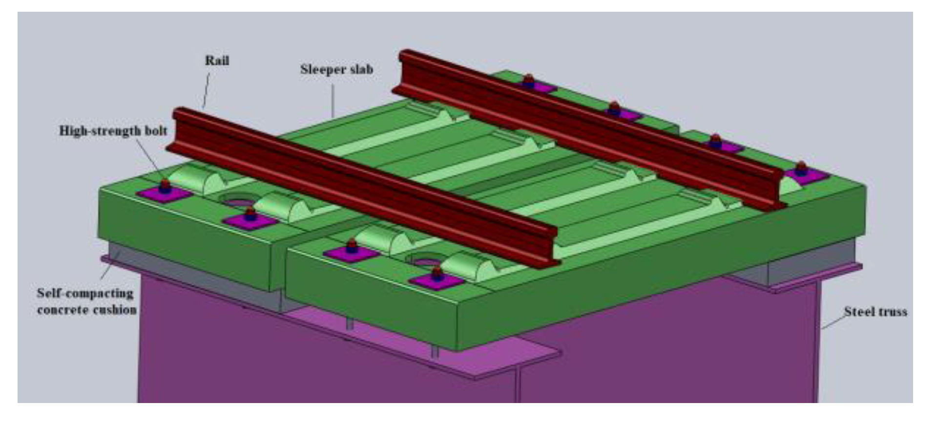
Nansha Port Railway in Guangzhou is a mixed passenger and freight railway with a design speed of 120 km/h. It has a through bridge with a steel truss and arch. The total length of the bridge is 996 m. In order to prolong the maintenance period of the track structure and reduce the secondary dead load of the bridge, a new type of concrete sleeper slab track structure on the open deck was adopted. The integrity of the structure was improved by prefabricating two sleepers into one and setting up vertical and horizontal limit devices. The adjusting cushion, sleeper slab, and cushion under the slab were set up between the sleeper slab and the steel beam. High strength bolts were used to connect the structure vertically, as shown in Figure 1. In practical engineering, the train operation produces a large vertical force and when the train passes through the curve section or has a hunting motion, it produces a large transverse force. Furthermore, the train operation, breaking, and passing through the ramp also produces a large longitudinal force. The coupling effect of the three-dimensional force has a great impact on the track structure and even damages it [22,23]. In order to study the mechanical properties and long-term performance of the new type of sleeper slab track structure, this paper carried out a full-scale indoor modal loading test of the concrete sleeper slab track structure to provide a reference for the engineering application.

2. Specimen Geometry and Materials

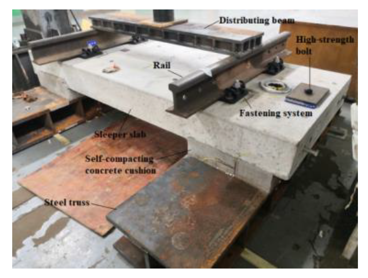
The indoor full-scale sleeper slab track structure consists of a rail, fastening system, sleeper slab, self-compacting concrete cushion, and flange slabs of steel truss bridge (simulated by two steel beams), as shown in Figure 2. The sleeper slab and the self-compacting concrete are made of C60 and C40 concrete, respectively. The concrete specimens were cured under the same conditions and the dimensions are 150 mm × 150 mm × 150 mm. After 28 days, the cube compressive strengths measured by the prefabrication plant are 70.1 and 48.4 MPa. The steel beams are elastically supported within a certain range (the support spacing is 1.6 m) in order to simulate the vertical deformation of the steel truss bridge and the support form of the track structure in practical engineering.
In the test, the dimensions of the sleeper slab are 1200 mm (length) × 2720 mm (width) × 240 mm (height) and each sleeper slab is made of double sleepers with a spacing of 625 mm between them. The dimensions of the self-compacting concrete cushion are 1150 mm (length) × 580 mm (width) × 120 mm (height), and each sleeper slab track structure has two symmetrical cushions. Moreover, the 60 kg/m rail is used in this structure, and the density is 7850 kg/m3.

3. Test Content

The test contents carried out in this paper include the vertical static load test, the vertical fatigue test, and horizontal resistance test of the sleeper slab. A PMS-500 digital display pulsing machine was used for vertical static load and sine cyclic load. A distribution beam was set on the middle of the track structure to simulate vehicle uniaxial load. The static load was 625 kN, which is 2.5 times the equivalent wheel load (250 kN) [24]. In the vertical static load test, the displacement and strain were measured by sensors to study the bearing capacity and force characteristics of the track structure. The transverse and longitudinal static loads on the sleeper slab were applied using a jack. In the test, the longitudinal and transverse forces adopted were F1 = 36 kN and F2 = 100 kN, respectively. The resistance of the horizontal limit device of the sleeper slab was studied by measuring the displacement of the sleeper slab relative to the steel beam. In the vertical fatigue test, the maximum load applied was 375 kN, which is 1.5 times the equivalent wheel load (250 kN), while the minimum load was 75 kN, which is 10% of the maximum load [14,25]. The train load conformed to the normal distribution; therefore, the cyclic load was set up as a sine form with 5 Hz and a total of 3 × 10⁶ cycles. In addition, the vertical static load test and horizontal resistance test were carried out after every 106 cycles to study the bearing capacity and durability of the sleeper slab track. The above tests are of great value to understand the mechanical properties of the new track structure.

3.1. Arrangements of Strain Gauges

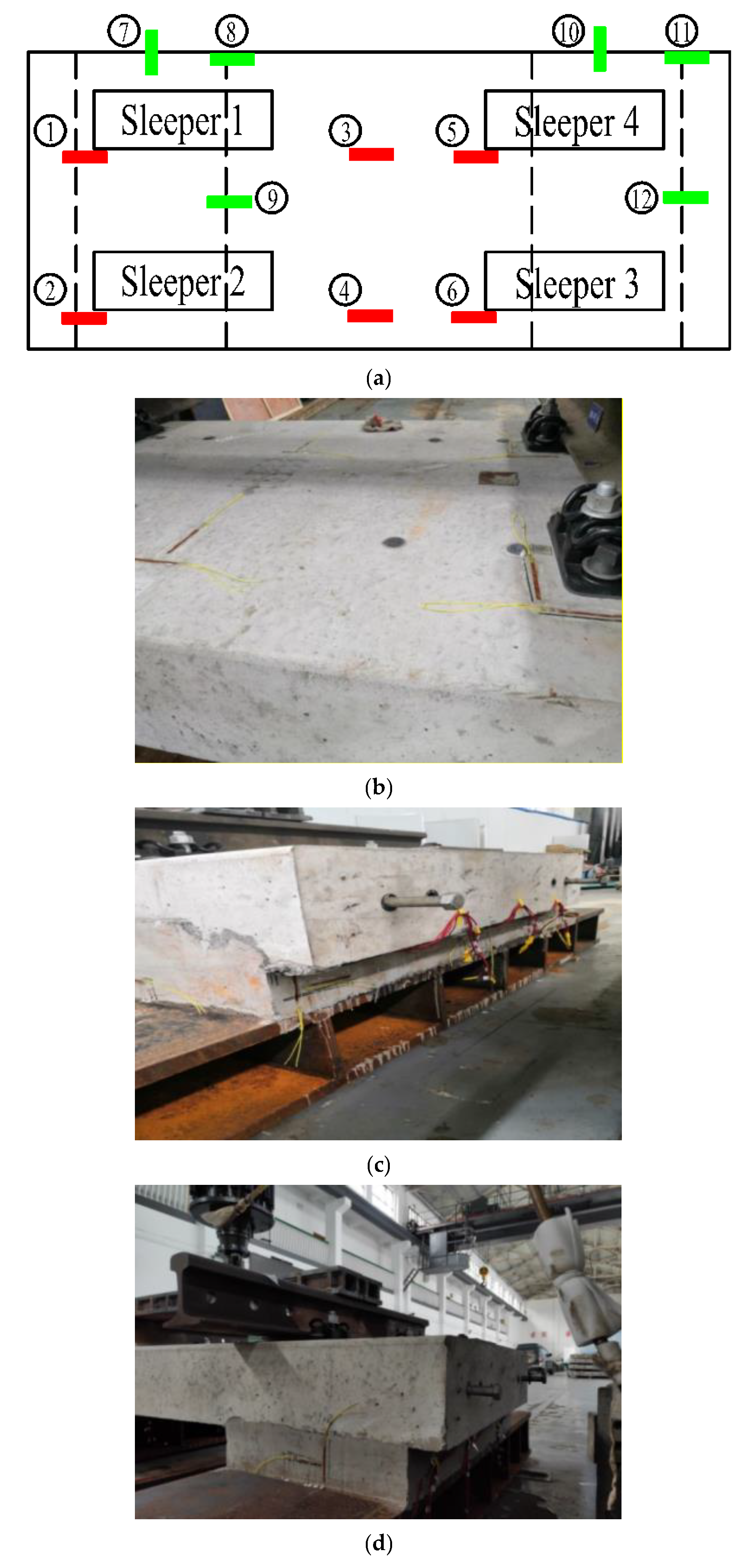
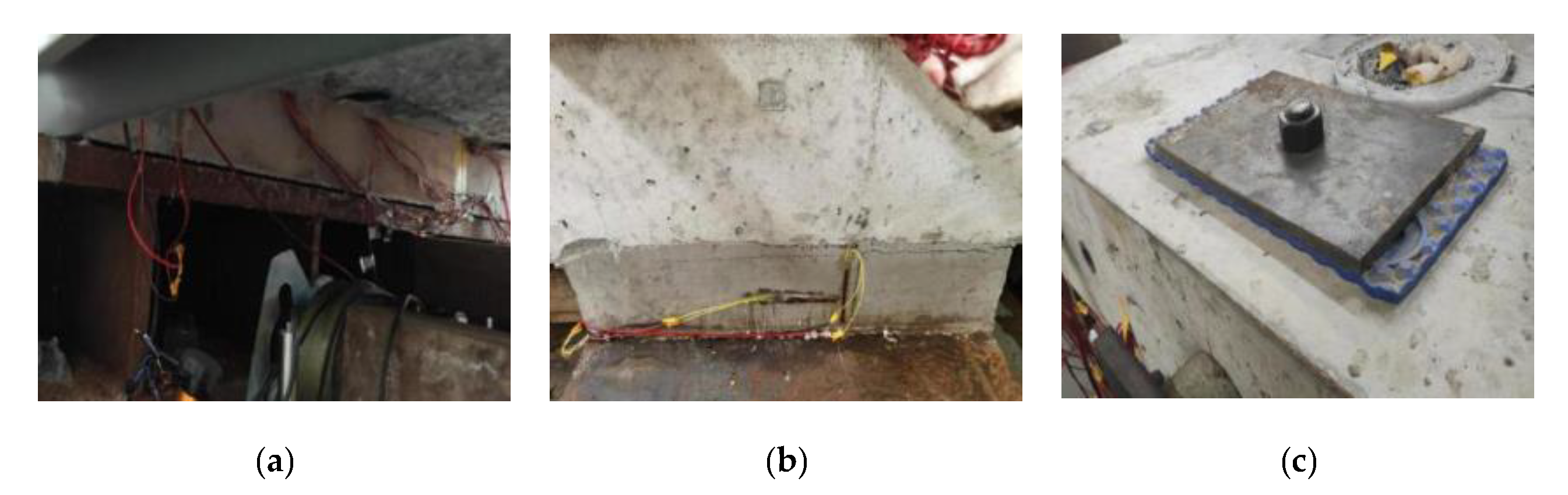
When the track structure bears the train load, the concrete strain at the edge is the most unfavorable. Therefore, the strain state of the concrete at the edge is studied emphatically in this paper. To avoid the damage of concrete strain gauges, the surfaces of the strain gauges were protected with structural glue. There were a total of 12 measuring points on the structure. Among them, the sleeper slab and the self-compacting concrete cushion had six measuring points, respectively. The arrangements of the measuring points are shown in Figure 3.
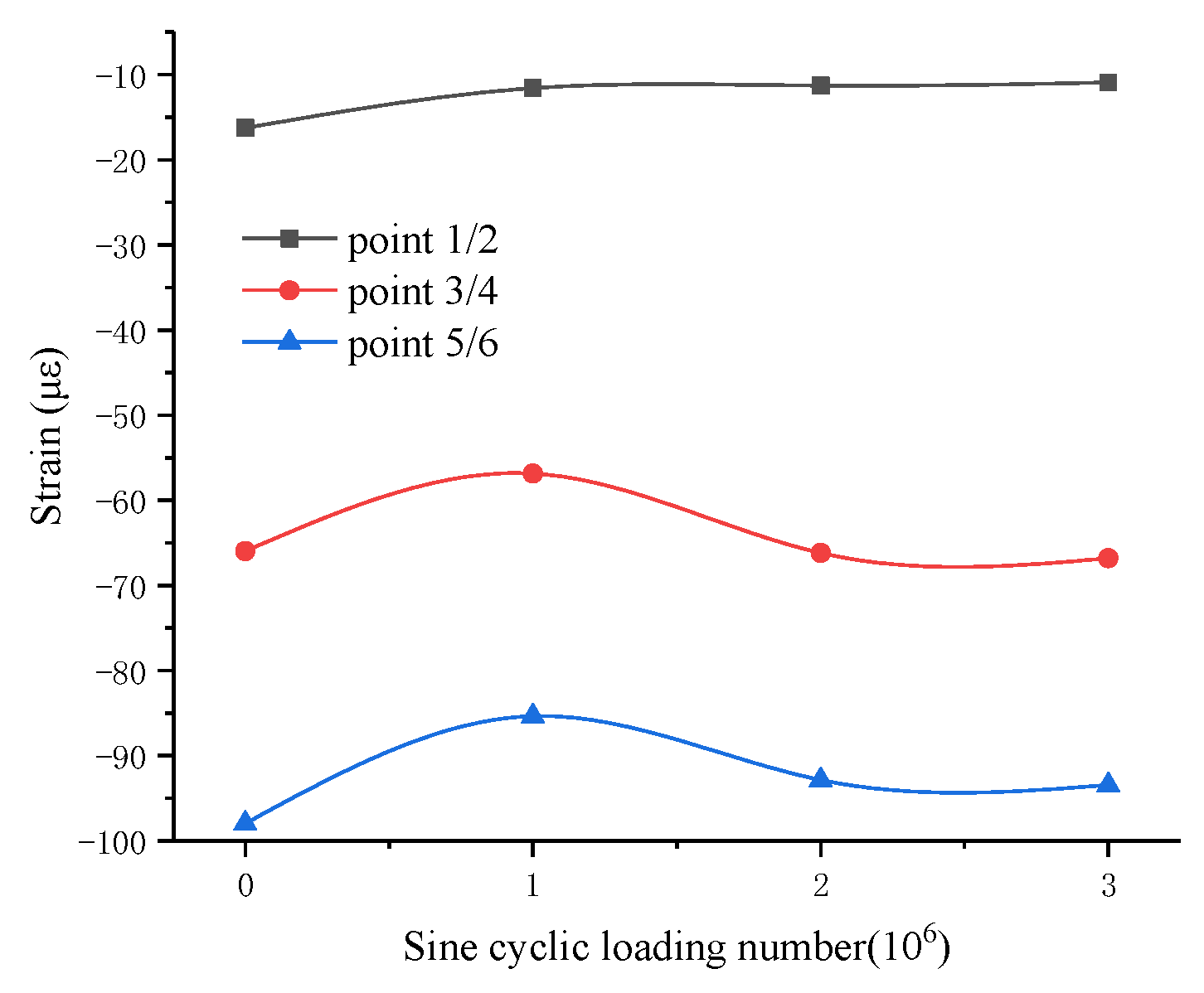
On the sleeper slab, 1, 2, 5, and 6 are the angle crack measuring points of the sleeper slab. Points 3 and 4 are the middle measuring points of the sleeper slab.
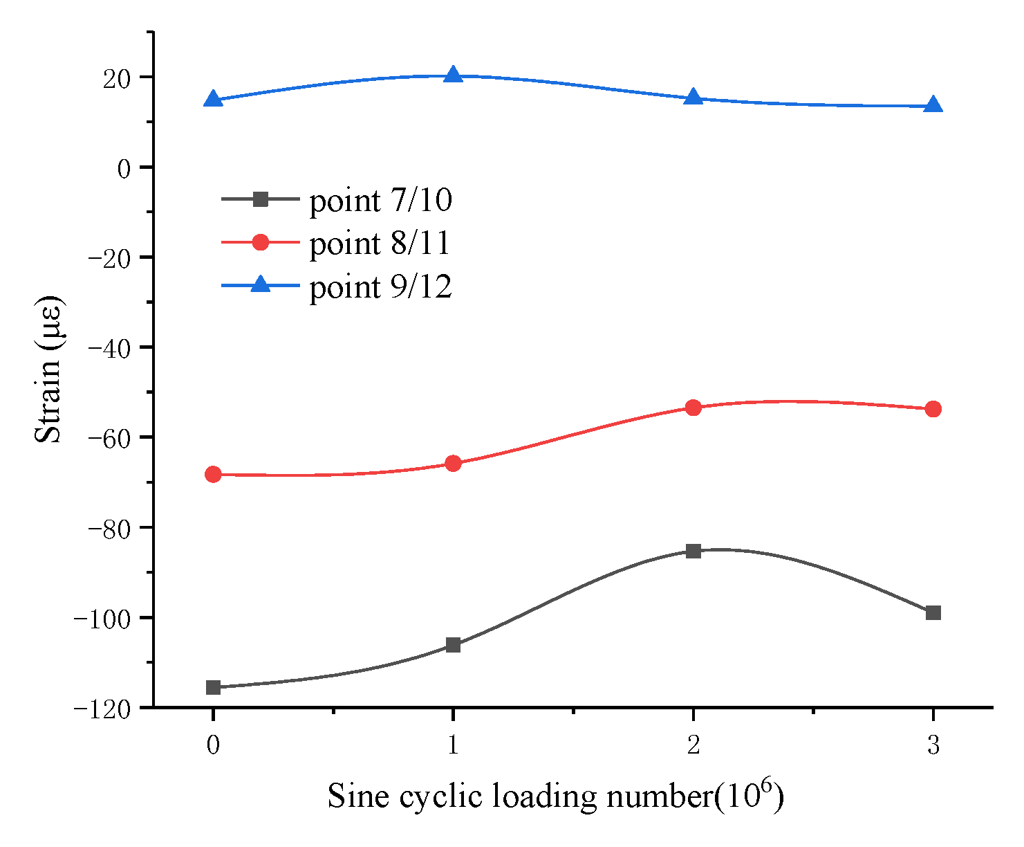
On the self-compacting concrete cushion, 7 and 10 are the middle measuring points of the short side; 8 and 11 are the end measuring points of the right long side; and 9 and 12 are the middle measuring points of the right long side. The measuring points of the self-compacting concrete cushion are at the middle height of the sides.

3.2. Arrangements of Displacement Sensors

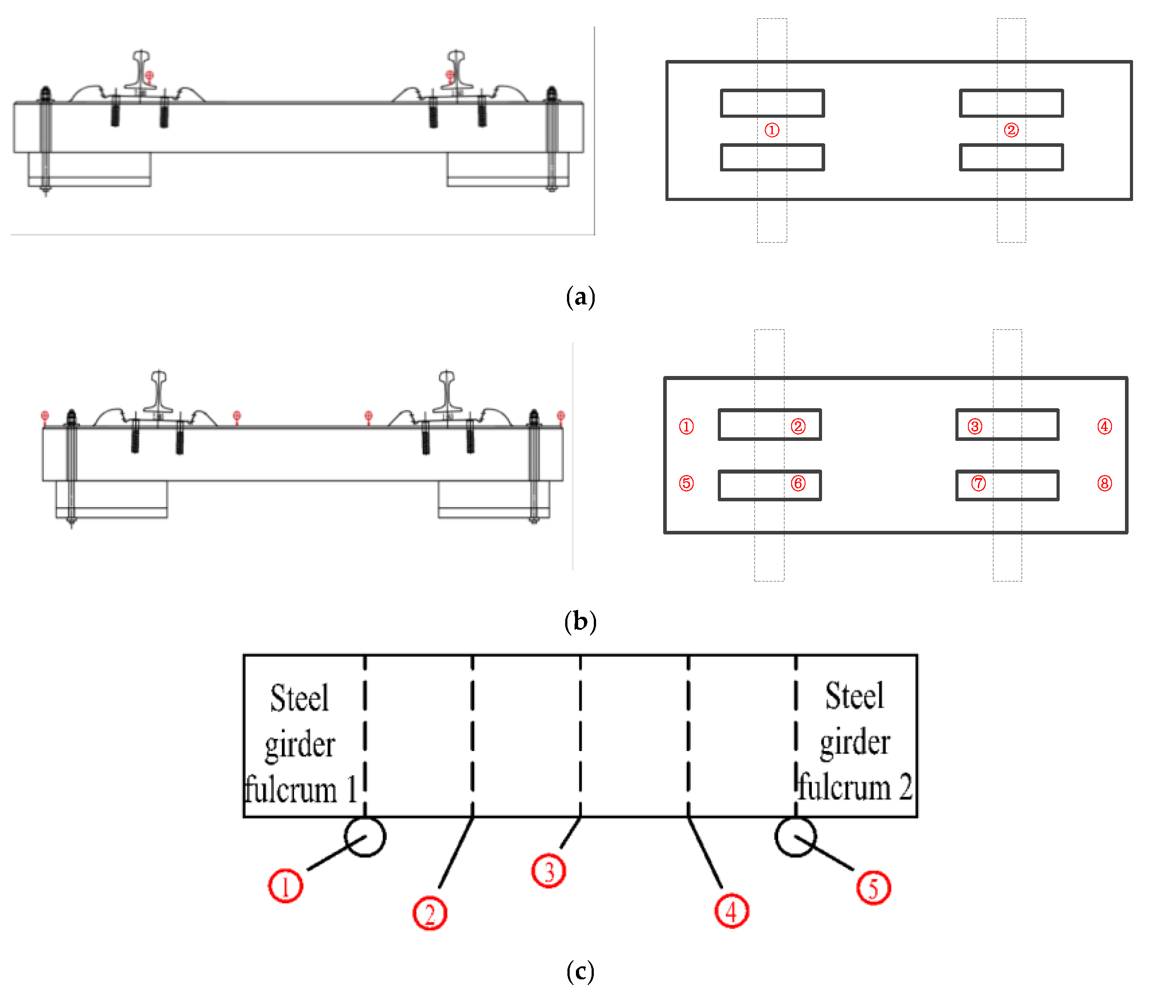
3.2.1. Vertical Displacement of Static Load Test

A total of 15 vertical displacement sensors were arranged on the structure. The arrangements were as follows: two rail displacement sensors were used to measure the rail displacement relative to the sleeper slab; eight sleeper displacement sensors were used to measure the sleeper slab displacement relative to the steel beam; and five steel beam displacement sensors were used to measure the displacement of the steel beam fulcrum, middle position, and quarter position. The arrangements of the measuring points are shown in Figure 4.

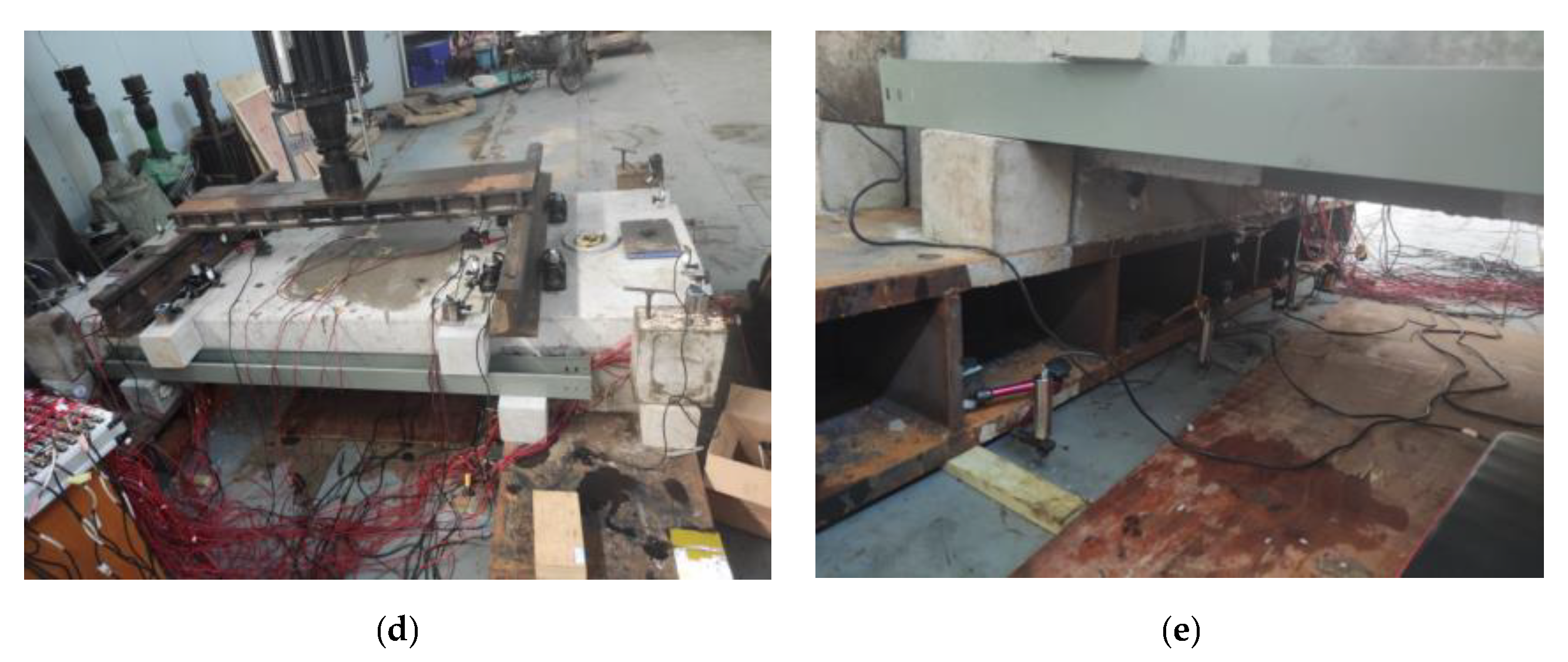
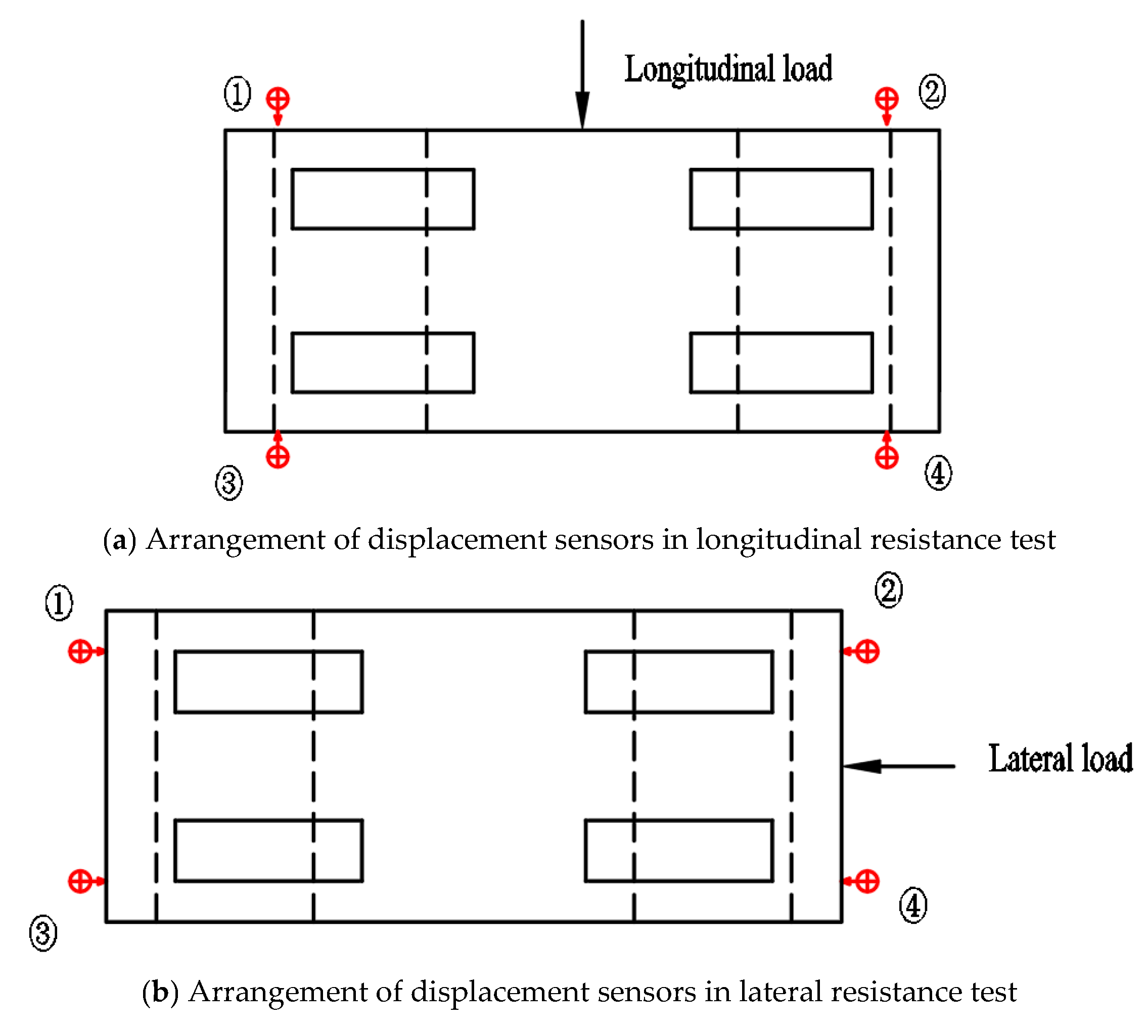
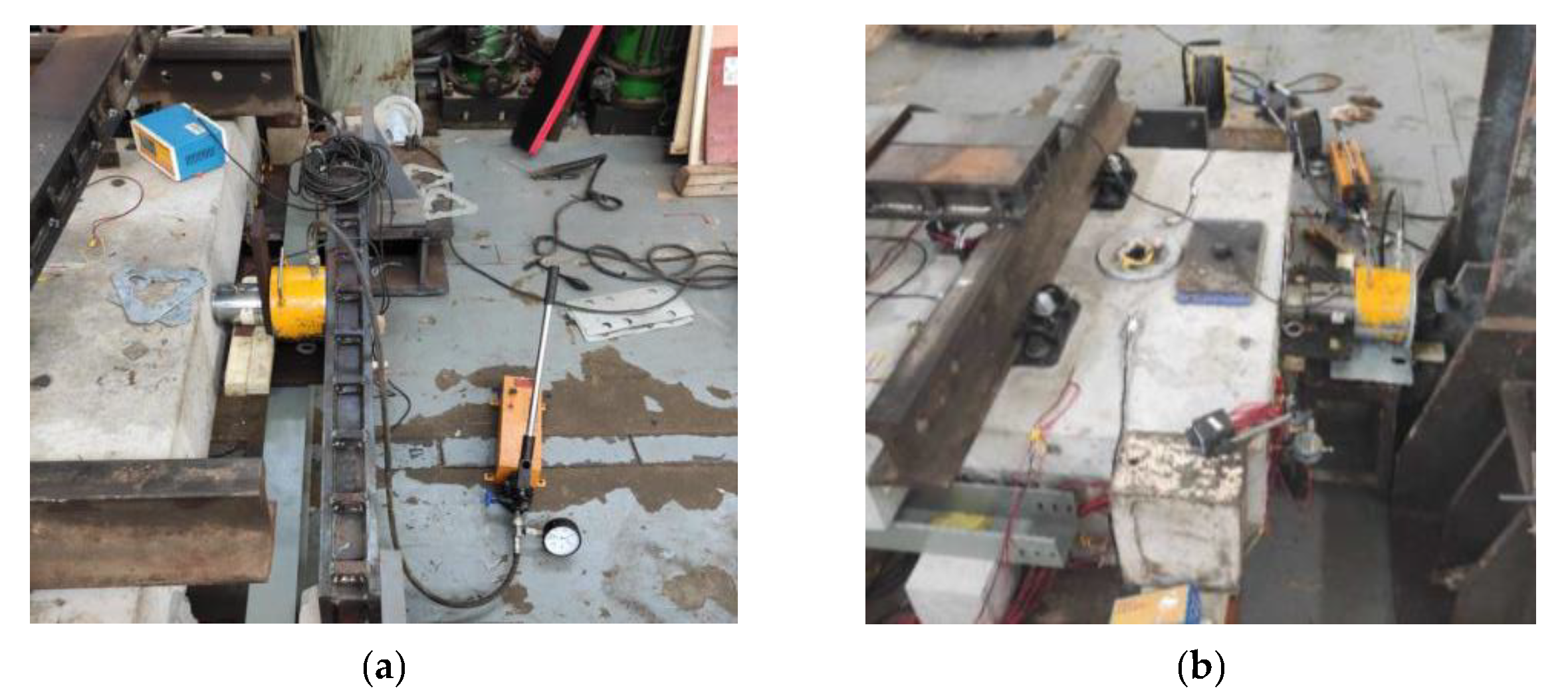
3.2.2. Horizontal Displacement of Resistance Test

In the horizontal resistance test, a total of eight horizontal displacement sensors were arranged on the structure. This included four longitudinal displacement sensors and four transverse displacement sensors. These sensors were used to measure the displacement of the sleeper slab relative to the steel beam in the horizontal direction. The arrangements of the measuring points are shown in Figure 5, and the loading devices used in the horizontal resistance test are shown in Figure 6.

4. Test Results

4.1. Strain of the Sleeper Slab Track

The strain variation law of the track structure under 2.5 times the train load after different sine cycles is shown in Table 1 and Table 2 and Figure 7 and Figure 8.
The development of the surface strain of the sleeper slab under the sine cyclic loading process is shown in Table 1 and Figure 7. The upper surface of the sleeper slab was in the compressive state during loading. The strain at the inner side of the sleeper (5 and 6) was greater than that at the middle of the slab upper surface (3 and 4), and the strain at the outside of the sleeper (1 and 2) was the smallest among the strain measuring points of the slab. During the sine cyclic loading process, the surface strain of the sleeper slab varied slightly. The average strain change rate of measuring points 5 and 6 was −4.594%. The average strain change rate of measuring points 3 and 4 was 1.263%. Only the average strain change rate of measuring points 1 and 2 reached −32.878%. This is probably because the strain values of 1 and 2 are very small. It can be seen from the above data that the sleeper slab can still maintain excellent mechanical properties after 3 million cycles of sine cyclic loading. It is well known that one of the main functions of the sleeper is to transfer the huge pressure from the rail to the track bed. The corner of the sleeper is a bulge, which can easily cause strain concentration. It has been demonstrated that the strain here is in a large state [26]. In the test, measuring points 5 and 6 were not only located at the corner of the sleeper, but also at the outside of the self-compacting concrete cushion, which means that the bottom of points 5 and 6 was in the suspended state. As a result, the location of maximum transverse compressive strain was at the inner side of the sleeper, and the average value was 97.944 με. Although measuring points 1 and 2 were also located at the corner of the sleeper, the strain was relatively small due to the concrete cushion support at the bottom.
The development of the vertical strain of the cushion under the sine cyclic loading process is shown in Table 2 and Figure 8. The vertical strain of the cushion at the middle position of the short side was compressive strain, that at the middle position of the long side was tensile strain, and that at the corner was compressive strain. The values of tensile and compressive strain were kept at low levels. During the sine cyclic loading process, the tensile strain at the long side of the cushion remained stable. The average strain change rate of measuring points 9 and 12 was −8.974%. The average compressive strain at the short side and the corner had a gradual decrease first and then increased slightly. After 3 million cycles of sine cyclic loading, the average strain change rates of measuring points 7 and 10 and 8 and 11 were −14.384 and −21.211%, respectively. The location of maximum tensile strain was at the middle of the long side with a value of 31.846 με (1 million). The location of maximum compressive strain was at the middle of the short side with a value of 142.400 με (3 million).
It can be seen from Figure 7 and Figure 8 that when the number of cyclic loading is low, the strain of the sleeper slab and self-compacting concrete cushion is reduced, which may be due to the loose contact between the track structures in the early stage. After 1 million cycles of sine cyclic loading, the fatigue deformation accumulation of the sleeper slab concrete could be observed. After 2 million cycles of sine cyclic loading, the fatigue deformation accumulation of the self-compacting concrete cushion could also be observed. Compared with the strain before cyclic loading, there was only a small change in concrete strain after 3 million cycles of sine cyclic loading. The fatigue damage of the structure was in a low state.

4.2. Vertical Displacement of the Sleeper Slab Track

Table 3, Table 4, and Table 5 show the displacement variation of the rail, sleeper slab, and steel beam under 2.5 times the train load (625 kN) after certain sine cyclic loading numbers.
According to Figure 9, the displacement of the rail relative to the sleeper slab decreased during the loading process of 1 million cycles. Before the cyclic loading, the contact between the rail and fastener system was not tight enough. This resulted in a large displacement of the rail under the vertical load of 625 kN. Under the action of cyclic loading, the loose state was eliminated rapidly, and the displacement of the rail after 1 million cycles of sine cyclic loading was less than before. Moreover, the loading position was in the middle of the two fasteners, which is the most unfavorable position as discussed by Gao et al. [27]. When the vertical load was applied on the rail, because of its bending stiffness, the force at the front and end of the fasteners was not consistent, and the pad was not in uniform force. As a result, only part of the nominal contact area was effective, which led to the reduction in fastener supporting stiffness. The above discussion is similar to the research of Chen et al. [28]. With the growth of the sine cyclic loading numbers, the rail displacement increased gradually. This result may be explained by the fact that the reduction in the fastener clamping force and the supporting stiffness occurred under the action of cyclic loading. The displacement variation of the sleeper slab is also described in Figure 9. As the sleeper slab, self-compacting concrete cushion, and steel beam are not a whole and there is the certain gap between the above components, the displacement of the sleeper slab relative to the steel beam increased during the initial 1 million loading cycles. With the gradual compaction between the components of the track structure, the relative displacement of the sleeper slab gradually decreased and tended to be stable in the later stage of the test.
Figure 10 shows the deformation trend of the steel beam relative to the ground during the sine cyclic loading process. The track components did not have tight contact at the initial time and the structural integrity was not in the best condition, which led to the increase in the steel beam displacement after 1 million cycles of sine cyclic loading. After that, with the growth of the sine cyclic loading numbers, the stiffness of the rubber fulcrum increased gradually. Consequently, the displacement of the whole steel beam began to decrease. What can be clearly seen in Figure 10 is that the deformation law of the steel beam is almost the same during the loading process. The displacement value of the midspan (point 3) was always less than that of the 1/4 span (point 2 and 4) from 1 million to 3 million cycles of cyclic loading. This illustrates that the rib structure can effectively improve the bending stiffness and reduce the midspan displacement. The difference between the total displacement of the steel beam (measured by sensors) and the displacement of the fulcrum is defined as the actual displacement. After 3 million cycles of sine cyclic loading, the maximum displacement change rate of the steel beam was 11.005%. As a result, the structure was still in good working condition.

4.3. Horizontal Displacement of Sleeper Slab

In the sleeper slab track structure, high-strength bolts are mainly used to provide the horizontal limit. Unfortunately, the long-term effect of train load may lead to a reduction in the binding force of the limit device. The main aim of this section was to investigate the horizontal resistance of the sleeper slab after certain sine cyclic loading numbers.

4.3.1. Longitudinal Loading

The longitudinal resistance test was carried out on a sleeper slab with a longitudinal thrust of F1 = 36 kN. The maximum longitudinal displacement of the sleeper slab under different sine cyclic loading numbers is shown in Table 6
According to Table 6, with the increase in sine cyclic loading numbers, the maximum longitudinal displacement of the sleeper slab increased first and then tended to stabilize gradually. When the sine cyclic loading number varied from 1 million to 3 million, the longitudinal displacement increased by 81.5%. According to the test results, after 3 million cycles of sine cyclic loading, the displacement of the sleeper slab was only 0.049 mm under the action of thrust. Consequently, the track structure can still maintain a strong transverse restraint.

4.3.2. Transverse Loading

A transverse resistance test was carried out on the sleeper slab with the transverse thrust of F2 = 100 kN. The maximum transverse displacement of the sleeper slab under different sine cyclic loading numbers is shown in Table 7.
According to Table 7, with the increase in sine cyclic loading numbers, the maximum transverse displacement of the sleeper slab continuously increased. When the sine cyclic loading number varied from 1 million to 3 million, the transverse displacement increased by 13.7%, and the maximum transverse displacement of the sleeper slab was recorded as 0.290 mm. These results indicate that the track structure has its usual strong transverse restraint after 3 million cycles of sine cyclic loading.

4.4. Horizontal Failure Test of Sleeper Slab Track

Under the action of transverse thrust F2 (100 kN), the maximum transverse displacement of the sleeper slab after 3 million cycles of sine cyclic loading was 0.290 mm, and the structure had no damage. To obtain the maximum transverse load that the structure could bear, the transverse thrust was continuously increased. During the loading process, the lateral displacement of the sleeper slab was recorded, and the status of the structure components was observed. The criterion for transverse damage of the track structure is defined as follows: a sharp increase in the displacement occurs when the load reaches a certain degree. Finally, the maximum transverse thrust that caused damage to the track structure was recorded as 413.4 kN. After the appearance of damage, loading was continuously applied to the track in the longitudinal direction. As a result, the longitudinal thrust of the structure was still more than 100 kN. Overall, these results indicate that the track structure has good performance in horizontal load resistance.
After the transverse failure test of the sleeper slab track, the main failure modes observed were as follows: the separation between the self-compacting concrete cushion and the steel beam, the crack between the self-compacting concrete cushion and the sleeper slab, and the deformation of the iron plate at the bolt position, as shown in Figure 11. These findings may help us to detect the unfavorable position of the sleeper slab track structure, thereby allowing maintenance staff to focus on the inspection of the above position.

5. Conclusions

In the present paper, full-scale laboratory tests on the sleeper slab track structure were proposed, consisting of the vertical static load test, vertical fatigue test, and horizontal resistance test. From the test results, the mechanical characteristics and fatigue behavior of the sleeper slab track were evaluated. The conclusions of this research are as follows.
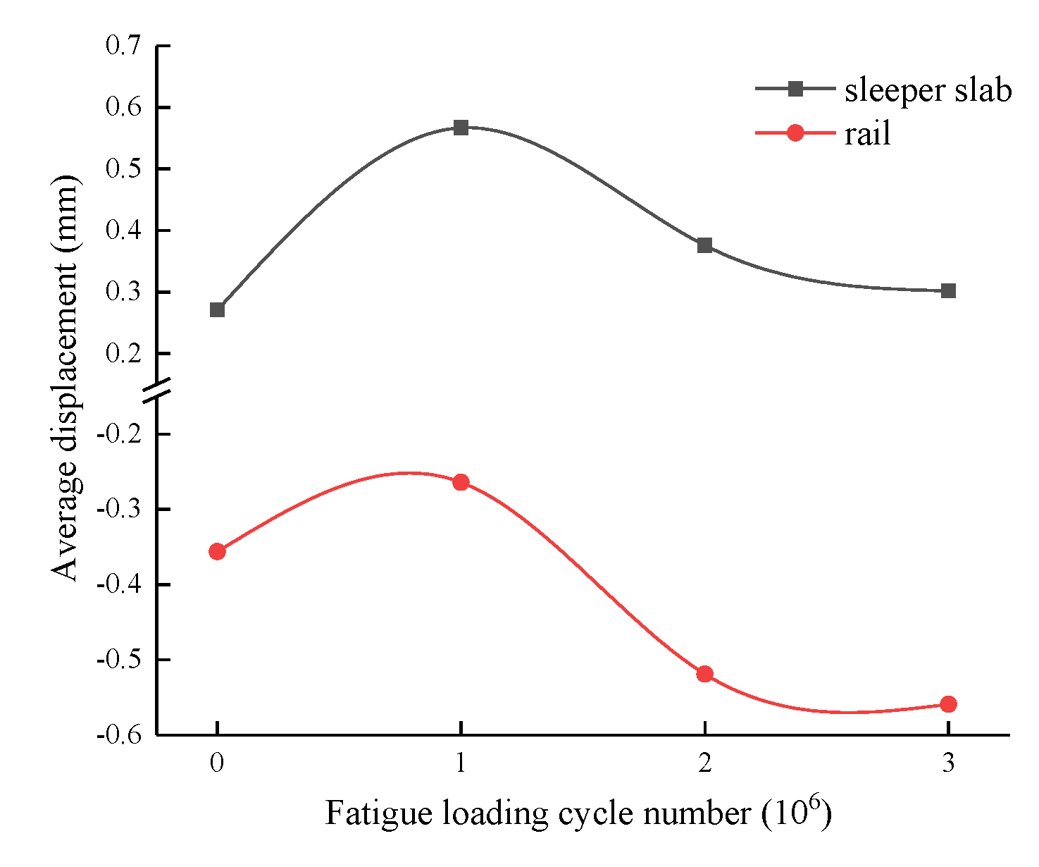
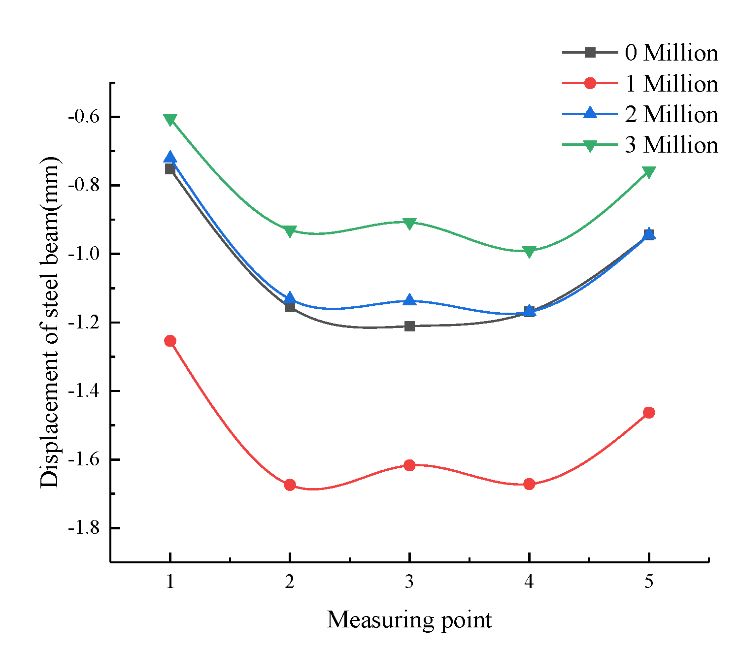
These experiments confirmed that after 3 million cycles of sine cyclic loading, the sleeper slab track is considered to maintain excellent mechanical properties. As the number of loading cycles increased, the strain of the sleeper slab and self-compacting cushion varied slowly. The unfavorable positions were found in the inner side of the sleeper, the mid-span of the slab, and the middle of the short side of the cushion. Compared with the strain, the change in vertical displacement was considered to be more obvious due to the stiffness change under the action of cyclic loading.
The results of the transverse ultimate resistance test indicate that failure occurred in the track structure when the transverse force reached 413.4 kN. The main failure modes were separation between the self-compacting concrete cushion and steel beam, crack between the sleeper slab and cushion, and deformation of the iron plate at the bolt position. In addition, the longitudinal resistance test also showed that the track structure can still bear a longitudinal force of up to 100 kN after transverse failure.
The new type of track structure proposed in this paper is planned to be applied to the long-span steel truss bridge to overcome the weaknesses of the traditional track structure on the open deck, such as poor integrity, difficult sustenance of track geometry, and heavy maintenance work. The main purposes of the current study were to verify the applicability of the sleeper slab track on the long-span steel truss bridge and to investigate the mechanical characteristics during the fatigue process with an experimental method. In order to investigate the performance parameters of the track structure more comprehensively, future work to be performed by the authors will be focused on the precise numerical simulation of the track structure.

Author Contributions

Conceptualization, Z.Z. (Zhiping Zeng) and W.W.; methodology, X.H. and D.W.; software, X.H.; validation, X.H. and D.W.; formal analysis, X.H. and D.W.; investigation, X.H. and D.W.; re-sources, Z.Z. (Zhiping Zeng), B.Z., and Z.Z. (Zheng Zhang); data curation, X.H. and D.W.; writ-ing—original draft preparation, X.H.; writing—review and editing, W.W.; visualization, X.H. and D.W.; supervision, Z.Z. and W.W.; project administration, X.H. and D.W.; funding acquisition, Z.Z. (Zhiping Zeng), B.Z., and Z.Z. (Zheng Zhang). All authors have read and agreed to the pub-lished version of the manuscript.

Funding

This research was funded by the High-speed Railway Joint Fund of National Natural Science Foundation of China, grant number U1734208; the Hunan Provincial Natural Science Foundation of China, grant number 2019JJ40384; and the Fundamental Research Funds for the Central Universities of Central South University, grant number 2019zzts873.

Data Availability Statement

All data, models, and code generated or used during the study appear in the submitted article.

Conflicts of Interest

The authors declare no potential conflicts of interest with respect to the research, authorship, and/or publication of this article.

References

  1. Cheng, Y.S.; Au, F.T.K.; Cheung, Y.K. Vibration of railway bridges under a moving train by using bridge-track-vehicle element. Eng. Struct. 2001, 23, 1597–1606. [Google Scholar] [CrossRef]
  2. Lou, P.; Zeng, Q. Formulation of equations of motion of finite element form for vehicle-track-bridge interaction system with two types of vehicle model. Int. J. Numer. Meth. Eng. 2005, 62, 435–474. [Google Scholar] [CrossRef]
  3. Xiao, X.; Ren, W. A Versatile 3D Vehicle-Track-Bridge Element for Dynamic Analysis of the Railway Bridges under Moving Train Loads. Int. J. Struct. Stab. Dy. 2019, 19, 1950050. [Google Scholar] [CrossRef]
  4. Podworna, M.; Klasztorny, M. Vertical vibrations of composite bridge/track structure/high-speed train systems. Part 1: Series-of-types of steel-concrete bridges. Bull. Pol. Acad. Sci Tech. Sci. 2014, 62, 165–179. [Google Scholar] [CrossRef] [Green Version]
  5. Podworna, M.; Klasztorny, M. Vertical vibrations of composite bridge/track structure/high-speed train systems. Part 2: Physical and mathematical modelling. Bull. Pol. Acad. Sci. Tech. Sci. 2014, 62, 181–196. [Google Scholar] [CrossRef]
  6. Podworna, M.; Klasztorny, M. Vertical vibrations of composite bridge/track structure/high-speed train systems. Part 3: Deterministic and random vibrations of exemplary system. Bull. Pol. Acad. Scis. Tech. Sci. 2014, 62, 305–320. [Google Scholar] [CrossRef] [Green Version]
  7. Aursudkij, B.; Mcdowell, G.R.; Collop, A.C. Cyclic loading of railway ballast under triaxial conditions and in a railway test facility. Granul. Matter 2009, 11, 391–401. [Google Scholar] [CrossRef]
  8. Moaveni, M.; Tutumluer, E.; Hart, J.M.; Mchenry, M. Evaluation of Railroad Ballast Field Degradation Using an Image Analysis Approach; Springer International Publishing: Cham, Switzerland, 2017; pp. 106–120. [Google Scholar]
  9. Ruge, P.; Widarda, D.R.; Schmälzlin, G.; Bagayoko, L. Longitudinal track–bridge interaction due to sudden change of coupling interface. Comput. Struct. 2009, 87, 47–58. [Google Scholar] [CrossRef]
  10. Sheng, X.; Zheng, W.; Zhu, Z. Mechanical Behaviors and Fatigue Performances of Ballastless Tracks Laid on Long-Span Cable-Stayed Bridges with Different Arrangements. Sens. Basel 2019, 19, 4195. [Google Scholar] [CrossRef] [Green Version]
  11. Zheng, W.; Sheng, X.; Zhu, Z.; He, H. Experimental study on deformation characteristics of ballastless tracks under downward bending deformation of long-span cable-stayed bridge. Eng. Struct. 2020, 210, 110363. [Google Scholar] [CrossRef]
  12. Tazawa, E.; Miyazawa, S. Experimental study on mechanism of autogenous shrinkage of concrete. Cem. Concr. Res. 1995, 25, 1633–1638. [Google Scholar] [CrossRef]
  13. Zhu, S.; Cai, C. Interface damage and its effect on vibrations of slab track under temperature and vehicle dynamic loads. Int. J. Nonlin. Mech. 2014, 58, 222–232. [Google Scholar] [CrossRef]
  14. Tarifa, M.; Zhang, X.; Ruiz, G.; Poveda, E. Full-scale fatigue tests of precast reinforced concrete slabs for railway tracks. Eng. Struct. 2015, 100, 610–621. [Google Scholar] [CrossRef]
  15. Manalo, A.; Aravinthan, T.; Karunasena, W.; Ticoalu, A. A review of alternative materials for replacing existing timber sleepers. Compos. Struct. 2010, 92, 603–611. [Google Scholar] [CrossRef]
  16. Khalil, A.A.; Khalil, A.A. Mechanical Testing of Innovated Composite Polymer Material for using in Manufacture of Railway Sleepers. J. Polym. Environ. 2018, 26, 263–274. [Google Scholar] [CrossRef]
  17. Cantero, D.; Arvidsson, T.; Obrien, E.; Karoumi, R. Train–track–bridge modelling and review of parameters. Struct. Infrastruct. Eng. 2016, 12, 1051–1064. [Google Scholar]
  18. Manalo, A.C.; Aravinthan, T.; Karunasena, W.; Islam, M.M. Flexural behaviour of structural fibre composite sandwich beams in flatwise and edgewise positions. Compos. Struct. 2010, 92, 984–995. [Google Scholar] [CrossRef] [Green Version]
  19. Ferdous, W.; Manalo, A.; Aravinthan, T.; Erp, G.V. Design of epoxy resin based polymer concrete matrix for composite railway sleeper. 23rd Australasian Conference on the Mechanics of Structures and Materials (ACMSM23), Byron Bay, Australia, 9–12 December 2014. [Google Scholar]
  20. Ferdous, W.; Manalo, A.; Van Erp, G.; Aravinthan, T.; Kaewunruen, S.; Remennikov, A. Composite railway sleepers-Recent developments, challenges and future prospects. Compos. Struct. 2015, 134, 158–168. [Google Scholar] [CrossRef]
  21. Ferdous, W.; Manalo, A.; Aravinthan, T.; Remennikov, A. Recent developments and applications of composite railway sleepers. 2016.
  22. Xu, L.; Zhai, W. A three-dimensional dynamic model for train-track interactions. Appl. Math. Model. 2019, 76, 443–465. [Google Scholar] [CrossRef]
  23. Chang, C.; Ling, L.; Han, Z.; Wang, K.; Zhai, W.; Kaewunruen, S. High-Speed Train-Track-Bridge Dynamic Interaction considering Wheel-Rail Contact Nonlinearity due to Wheel Hollow Wear. Shock Vib. 2019, 2019, 1–18. [Google Scholar] [CrossRef]
  24. Chinese National Standards, TB 10621-2014. Code for Design of High-Speed Railway, China, 2014.
  25. Yu, Z.; Xie, Y.; Shan, Z.; Li, X. Fatigue Performance of CRTS III Slab Ballastless Track Structure un-der High-speed Train Load Based on Concrete Fatigue Damage Constitu-tive Law. J. Adv. Concr. Technol. 2018, 16, 233–249. [Google Scholar] [CrossRef] [Green Version]
  26. Guo, W.; Zeng, Z.; Li, S.; Wang, W.; Shuaibu, A.A.; Chen, Z. Experimental study on mechanical properties of heavy-haul low-vibration track under train static load. Sci. Prog. 2020, 103, 39847244–398472431. [Google Scholar] [CrossRef] [PubMed]
  27. Gao, L.; Zhao, W.; Hou, B. Research on vertical mechanical behavior of WJ-8 fastener under clamping force failure. Eng. Mech. 2020, 37, 228–237. [Google Scholar]
  28. Chen, Z.; Andrawes, B. A mechanistic model of lateral rail head deflection based on fastening system parameters. Proc. Inst. Mech. Eng. Part F J. Rail Rapid Transit 2017, 231, 999–1014. [Google Scholar] [CrossRef]
Figure 1. Sleeper slab track structure.
Applsci 11 05273 g001
Figure 2. Model of rail–sleeper slab combined track structure.
Applsci 11 05273 g002
Figure 3. Sensor arrangements of strain gauges. (a) Arrangements of strain gauges, (b) Upper surface of sleeper slab, (c) Long side of self-compacting concrete cushion and (d) Short side of self-compacting concrete cushion.
Applsci 11 05273 g003
Figure 4. Arrangement of vertical displacement measuring points. (a) Displacement measuring points of rail, (b) Displacement measuring points of sleeper slab, (c) Displacement measuring points of steel beam, (d) Displacement measuring points of rail and sleeper slab in lab and (e) Displacement measuring points of steel beam in lab.
Applsci 11 05273 g004aApplsci 11 05273 g004b
Figure 5. Arrangement of horizontal displacement measuring points.
Applsci 11 05273 g005
Figure 6. Loading devices used in horizontal resistance test. (a) Longitudinal load, (b) Lateral load.
Applsci 11 05273 g006
Figure 7. Surface strain of sleeper slab.
Applsci 11 05273 g007
Figure 8. Vertical strain of the cushion.
Applsci 11 05273 g008
Figure 9. Vertical displacement of rail and sleeper slab.
Applsci 11 05273 g009
Figure 10. Vertical displacement of steel beam.
Applsci 11 05273 g010
Figure 11. The main failure modes of structure. (a) Separation, (b) Crack, (c) Deformation of iron plate.
Applsci 11 05273 g011
Table 1. Surface strain of sleeper slab.
Sine Cyclic Loading NumbersBefore Cyclic Loads 1 Million2 Million3 Million
Strain (με)point 1−19.750 −14.028 −13.972 −12.417
point 2−12.778 −9.167 −8.583 −9.417
point 3−67.778 −59.639 −67.556 −67.722
point 4−64.139 −54.083 −64.833 −65.861
point 5−86.500 −73.028 −77.639 −77.028
point 6−109.389 −97.667 −108.056 −109.861
Note: positive value means pull, negative value means pressure.
Table 2. Vertical strain of the cushion.
Sine Cyclic Loading NumbersBefore Cyclic Loads1 Million2 Million3 Million
Strain (με)point 7−141.944 −134.800 −115.292 −142.400
point 8−75.778 −72.815 −63.846 −72.123
point 924.778 31.846 22.831 20.554
point 10−89.250 −77.538 −55.354 −55.538
point 11−60.750 −58.831 −43.169 −35.446
point 124.833 8.492 7.631 6.400
Note: positive value means pull, negative value means pressure.
Table 3. Average displacement of rail (relative to sleeper slab).
Sine Cyclic Loading NumbersBefore Cyclic Loads1 Million2 Million3 Million
Vertical displacement/mm−0.356−0.264−0.519−0.559
Table 4. Average displacement of sleeper slab (relative to steel beam).
Sine Cyclic Loading NumbersBefore Cyclic Loads1 Million2 Million3 Million
Vertical displacement/ mm0.2710.5670.3760.302
Table 5. Displacement of steel beams (relative to ground).
Measuring Points12345
0/mm−0.752−1.155−1.211−1.169−0.945
1 million/mm−1.254−1.674−1.617−1.672−1.463
2 million/mm−0.721−1.132−1.138−1.169−0.945
3 million/mm−0.605−0.930−0.908−0.990−0.757
Note: negative value means downward, positive value means upward.
Table 6. Maximum longitudinal displacement of sleeper slab (relative steel beam).
Sine Cyclic Loading Numbers1 Million2 Million3 Million
Longitudinal displacement/ mm0.0270.0500.049
Table 7. Maximum transverse displacement of sleeper slab (relative steel beam).
Sine Cyclic Loading Numbers1 Million2 Million3 Million
Transverse displacement/mm0.2550.2690.290
Publisher’s Note: MDPI stays neutral with regard to jurisdictional claims in published maps and institutional affiliations.

