Article

Fabrication of Hierarchical Multilayer Poly(Glycerol Sebacate urethane) Scaffolds Based on Ice-Templating

by
Andreas Samourides
1,
Andreas Anayiotos
1,
Konstantinos Kapnisis
1,
Zacharoula Xenou
1,
Vanessa Hearnden
2 and
Biqiong Chen
3,*
1
Department of Mechanical Engineering and Materials Science and Engineering, Cyprus University of Technology, Limassol 3036, Cyprus
2
Department of Materials Science and Engineering, Kroto Research Institute, University of Sheffield, Broad Lane, Sheffield S3 7HQ, UK
3
School of Mechanical and Aerospace Engineering, Queen’s University Belfast, Stranmillis Road, Belfast BT9 5AH, UK
*
Author to whom correspondence should be addressed.
Appl. Sci. 2021, 11(11), 5004; https://doi.org/10.3390/app11115004
Submission received: 24 March 2021 / Revised: 19 May 2021 / Accepted: 21 May 2021 / Published: 28 May 2021

Abstract

:
In this study, it was demonstrated that ice-templating via freeze drying with custom-made moulds, in combination with air brushing, allows for the fabrication of poly(glycerol sebacate urethane) (PGSU) scaffolds with hierarchical multilayer microstructures to replicate various native soft tissues. The PGSU scaffolds were either monolayered but exhibited an anisotropic microstructure, or bilayered and trilayered, with each layer showing different microstructures. By using freeze drying with custom-made moulds, the ice crystals of the solvent were grown unidirectionally, and after freeze-drying, the scaffolds had an anisotropic microstructure, mimicking tissues such as tendon and skeletal muscle. The anisotropic PGSU scaffolds were also examined for their tensile strength, and a range of mechanical properties were obtained by altering the reactants’ molar ratio and polymer concentration. This is of importance, since soft tissues exhibit different mechanical properties depending on their native location and functionality. By combining freeze drying with airbrushing, scaffolds were fabricated with a thin, non-porous layer on top of the porous layers to allow three-dimensional cell co-culture for tissues such as skin and oral mucosa. These results show that fabrication techniques can be combined to produce PGSU scaffolds with tailored hierarchical microstructures and mechanical properties for multiple tissue engineering applications.

Graphical Abstract

1. Introduction

Tissue engineering (TE) scaffolds temporarily provide the cells with a three-dimensional (3D) structure until the cells produce their own extracellular matrix (ECM) to replace the scaffold. Scaffolds should sustain cell growth and collagen production and provide guidance to the newly developed tissue [1]. Ideally, scaffolds should also mimic the native 3D ECM structure to guide cell growth in a specific direction and be produced in a reproducible and inexpensive manner. The scaffold microstructure is characterised by its porosity, pore size, pore shape, interconnectivity and orientation. Each of these parameters influences the physical properties (e.g., mechanical properties and degradation rate) and biological properties (e.g., cell proliferation, cell differentiation, collagen production and angiogenesis), and ultimately control the growth of the new tissue [2]. One of the main factors that influence the scaffold microstructure is the scaffold fabrication method, such as freeze drying, electrospinning or porogen leaching. Freeze drying is a fabrication technique that involves dissolving or suspending a material in a solvent, which is then frozen and sublimed, leaving a porous scaffold with a microstructure mirroring the ice crystals that formed during the freezing of the solution [3]. Therefore, by controlling the ice crystal growth during the freezing of the solution, the microstructure of the scaffold can be designed and manufactured to mimic the ECM of native tissues, a process called ice-templating (also known as modified thermal induced phase separation).
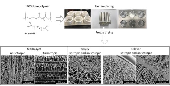
The focus of this study was to utilise ice-templating based on freeze drying and custom-made moulds, in combination with airbrushing to fabricate polymer scaffolds mimicking the microstructure of soft tissues such as skin, oral mucosa and tendon. Furthermore, it is also important to use a biomaterial that is capable of showing tuneable physical properties in order to match its properties as close as possible to the target tissue. A promising material to be used as a soft tissue engineering scaffold is a biocompatible and biodegradable elastomer, poly(glycerol sebacate urethane) (PGSU). Pereira et al. [4] showed that PGSU had tuneable mechanical properties and degradation rates by altering the molar ratio of the reactants, as well as excellent biological properties in vitro. They then proceeded to subcutaneously implant PGSU films in rat animal models for a 40-week period, examining the acute and chronic inflammatory response. No adverse reaction or any other complications were found over the 40-week period, and, at some time-points, the PGSU had less foreign body response compared to poly(lactic-co-glycolic acid) (PLGA), which is a Food and Drug Administration (FDA)-approved material for internal use. Frydrych et al. [5] used freeze drying to produce PGSU scaffolds and found that by reducing the ratio of glycerol:hexamethylene diissocyanate (HDI), the degradation rate of the scaffolds became slower, and the mechanical properties changed. Subsequently, a study by Samourides et al. [6] examined the control of the microstructure of PGSU scaffolds by altering the concentration of the PGSU pre-polymer in the freezing solution during fabrication. It was found that by increasing the pre-polymer concentration, the pore size became smaller, degradation rate was reduced and mechanical properties were enhanced. It was also demonstrated that the metabolic activity of fibroblast cells was not affected by the pore size, but the collagen production, angiogenesis and tissue ingrowth were significantly better for the PGSU scaffolds that had pore sizes around 28.2 μm when compared to the other scaffolds investigated [6].
To mimic the architecture of soft tissues, it is necessary to understand their microstructure and function. Skin tissue functions as a protective barrier to separate the underlying tissue from the environment. It consists of three layers: the hypodermis, dermis and epidermis (epithelium), of which the latter two are separated by a basement membrane (BM) [7]. Culturing a stratified epithelium, as found in the skin, requires an adhesive surface which is porous to nutrients but does not allow cell invasion to support the growth and differentiation of epithelial cells [8]. Fibroblast cells found in the lamina propria or dermis support the adhesion of epithelial cells and require a porous scaffold with interconnected pores which mimic the ECM structures found in native tissue. The hypodermis is a loose connective tissue with large pore, capable of supporting the growth of large adipocyte cells. For skin tissue, a biomimetic scaffold should exhibit three layers, i.e., two porous layers with different pore sizes to support fibroblasts and adipocytes, and a BM-like layer on top to provide a surface to which epithelial cells can attach and grow without infiltrating the other two layers. Tendon tissue is comprised of a single tissue layer populated with tenocytes, but has an oriented microstructure in the load axis to connect a muscle with a bone and transfer the forces induced from the muscle to the bone to create motion [9]. Therefore, the scaffold for tendon tissue should ideally have an oriented anisotropic, porous structure to allow tenocytes to penetrate, distribute and produce tendon tissue in a guided anisotropic structure.
Multilayer scaffolds were fabricated to mimic the multilayer structure of native tissues using various methods [10,11]. For example, silicon wafer moulds coated with a maltose-sacrificial layer were used to fabricate double-layer poly(glycerol sebacate) (PGS) porous scaffold with 50–250 μm pore size for the purpose of cardiac tissue engineering [10]. It was found that the bilayer structure of the scaffolds provided a platform for cell delivery, promoted cell growth and had mechanical properties similar to the normal heart muscle. However, the disadvantage of the micromoulding fabrication technique is that it requires multiple steps to prepare the moulds, involves a sacrificial layer to allow the detachment of the cast polymer and can only produce thin scaffolds, approximately 150 μm thick, which limits their scalability and application. In another study, casting, moulding and freeze drying techniques were used to develop a natural triple-layered vascular graft made out of collagen type I, fibrils and elastin fibres for vascular tissue engineering [11]. Three tubular moulds that had different sizes were used to build the scaffold layer by layer, and it was found that the scaffolds exhibited suitable morphologies and properties for vascular tissue engineering.
In addition, anisotropic monolayer scaffolds were also manufactured for tissues that require anisotropy [12]. The advantage of having oriented pore architecture is that it can mimic the natural in vivo ECM of those tissues which require alignment—for example, tendon and skeletal muscle. Successful attempts to fabricate scaffolds with anisotropic pore architecture by using freeze drying and custom-made moulds that either produced temperature gradient due to difference in the thermal conductivity between the mould materials [13,14,15,16], or submerged the solvent into a cold bath at a constant rate [17], were reported using various biomaterials, such as collagen, gelatin, poly(vinyl alcohol) and PLGA. The custom-made moulds were comprised of either a metal base and Perspex walls [13], polytetrafluoroethylene (PTFE) mould placed on a copper cold finger [14], metal base with polyethylene walls [15] or plastic tubes that had their walls further isolated with Styrofoam [16]. These moulds induced a temperature gradient during the freezing of the polymer solution, and after freeze drying, the resulting scaffolds exhibited anisotropic microstructures but, in some cases, the scaffold microstructures were characterised by a dense non-oriented layer at the bottom due to a higher cooling rate [13,14]. Generally, the scaffolds showed optimised mechanical properties in the direction of the pores, and the new ECM produced was aligned with the pores.
While multilayer and anisotropic monolayer scaffolds were fabricated before and showed promising results in multiple TE applications, the fabrication techniques used usually produce small-size scaffolds, require multiple steps and a long fabrication time, and have limited control between layer microfeatures (pore size, pore orientation, porosity etc.). This study aims to demonstrate the techniques of ice-templating and airbrushing that can be combined to fabricate large, complex, hierarchical structures in a controlled manner for soft TE. PGSU scaffolds were fabricated as two-layer, three-layer and anisotropic single layer. Ice-templating via freeze drying and custom-made moulds was utilised to produce large 3D porous scaffolds with controlled pore orientation and, in combination with airbrushing, a thin non-porous film could be deposited on top of the porous scaffold to mimic tissue structures that intrinsically exhibit a BM. Scanning electron microscopy (SEM) was used to characterise the microstructure of the PGSU scaffolds. To investigate the potential applications of the anisotropic PGSU scaffolds, a range of scaffolds were fabricated with multiple pre-polymer concentrations and glycerol:HDI molar ratios and tensile testing was used to evaluate the mechanical properties.

2. Materials and Methods

2.1. Materials

Sebacic acid (99%), glycerol (>99%), 1,4-dioxane (anhydrous, 99.8%), hexamethylene diisocyanate (99%) and Tin(II) 2-ethylexanoate were purchased from Sigma-Aldrich (Dorset, UK). The aluminium plate (grade 6082T6) was purchased from Aluminium Warehouse (Hatfield, Hertford, UK) and polytetrafluoroethylene (PTFE) virgin rod was purchased from Plastock (Buckinghamshire, UK).

2.2. Methods

2.2.1. Synthesis of PGSU Pre-Polymers

Based on previously reported methods [18], PGS pre-polymer (pre-PGS) was synthesised at a 1:1 molar ratio between sebacic acid and glycerol. Both monomers were mixed in a three-neck flask, which was attached to a Dean-Stark trap with a condenser and nitrogen flow. The mixture was allowed to react at 120 °C under stirring and a low nitrogen flow for 72 h. Highly viscous pre-PGS was then formed and stored in a container at room temperature prior to use.
Porous PGSU scaffolds were synthesised under multiple synthesis parameters in order to control the pore size, porosity and mechanical properties of the scaffolds.
Firstly, for the multilayer scaffolds, PGSU pre-polymer was synthesised by dissolving pre-PGS into 1,4-dioxane at the required concentrations (5, 10 and 15 w/v%) and pre heated to 55 °C with 0.05 w/v% of Tin(II) 2-ethylexanoate. Once heated, HDI was added at a 1:0.6 molar ratio (glycerol:HDI) and left at 55 °C for 5 h under constant stirring. For ease of documentation, the nomenclature of the samples is PGSU-X where X refers to the concentration of the PGSU pre-polymer (w/v%), 5%, 10% and 15%, in the solvent.
The pre-polymer for the anisotropic scaffolds was synthesised with the same reaction conditions as those for the multilayer scaffolds, except the PGSU pre-polymer concentration used were 10, 15 and 20 w/v% in the solvent and glycerol:HDI molar ratios were equal to 1:0.6, 1:0.8 and 1:1.0. The synthesis and fabrication parameters as well as the nomenclature of the fabricated scaffolds are shown in Table 1.

2.2.2. Design of Ice-Templating Moulds

To control the orientation of the porous microstructure of the scaffolds, three moulds were designed and build in-house to produce scaffolds with isotropic pores and anisotropic pores. One of the moulds was built with aluminium all-around (Figure S1A1,A2; Supplementary Content). It was hypothesised that heat would be isotropically directed into the solution to produce isotropic ice structure and, after freeze drying, an isotropic scaffold. This mould is termed as “mould-isotropic”. The other two moulds were comprised of aluminium base and PTFE walls. Adding the PTFE walls to the aluminium base, a difference in thermal conductivity was created, and heat was expected to be directed anisotropically into the PGSU solution, forming oriented ice crystals. For this purpose, the moulds were designed in different shapes to create different pore orientations within the scaffold (Figure S1B1,B2,C1,C2; Supplementary Content). The mould designed to produce pore orientation perpendicular to the scaffold will be referred to as “mould-perpendicular”, and the mould for pore orientation parallel to the scaffold will be referred to as “mould-parallel”. In both cases, pores were expected to orient perpendicular to the bottom surface of the mould (i.e., the surface in contact with the shelf of the freezing chamber). In the case of mould-perpendicular, the produced scaffold was investigated directly as fabricated, without turning it around (Figure S2A2,B2; Supplementary Content), while, in the case of mould-parallel, the scaffold produced was rotated by 90° to consider the perpendicular direction as the parallel direction (Figure S2C2,C3; Supplementary Content) in order to mechanically test the scaffolds along the pore orientation direction. For both moulds, the PTFE walls were detachable to allow for easy removal of the scaffolds.

2.2.3. Preparation of PGSU Scaffolds

Monolayer PGSU Scaffolds with Controlled Pore Orientation

PGSU pre-polymer solution was cast into either mould-perpendicular or mould-parallel depending on the desired scaffold dimensions. For the pore orientation perpendicular to the scaffold (referred to as PGSU-perpendicular), the pre-polymer concentration was kept at 10% (w/v) only, whereas, for the pore orientation parallel to the scaffold (referred to as PGSU-parallel), eight different scaffolds were fabricated with a pre-polymer concentration ranging from 10 to 20% (w/v) and glycerol:HDI molar ratio from 1:0.6 to 1:1.0. The samples were placed in a freeze dryer (FreeZone Triad Dry System, Labconco Co., Kansas City, MO, USA) set at −50 °C and left for 3 h for the solution to completely freeze. The lyophilisation process then started with the shelf temperature heated at a rate of 1 °C/min to 0 °C and left for 16 h under vacuum pressure (0.1 mbar). For the secondary drying stage, the temperature was increased at a rate of 1 °C/min to 40 °C for another 24 h.

Multilayer PGSU Scaffolds

The multilayer scaffolds are composed of layers that have different microstructures. The fabrication was done by building the scaffold layer by layer.
A double-layer scaffold was composed of two layers of PGSU-10% and PGSU-15% (referred to as PGSU-bilayer). To fabricate the PGSU-bilayer, PGSU-10% solution was cast into mould-isotropic and left to freeze at −50 °C for 2 h in the freeze drier. After 2 h, the solution was completely frozen and PGSU-15% solution was cast on top of the frozen PGSU-10%. However, before casting the temperature of the pre-polymer solution was reduced from 55 °C (see Section 2.2.1) to 15 °C (just above the melting point of 1,4-dioxane: 11.7 °C), which was then cast on top of the already frozen base layer (PGSU-10%), allowing its surface to defrost and immediately freeze back. The mould was subsequently placed back into the freeze drier and the freeze drying cycle described before was performed.
A three-layer scaffold was fabricated based on the above bilayer scaffold, with a thin non-porous film on top (to resemble the basement membrane of skin). This trilayer scaffold was built from base to top, and it is referred to as a PGSU-trilayer. To fabricate this scaffold, the same method as that of PGSU-bilayer was used, with PGSU-10% at the bottom and PGSU-15% on top of it. The now 2-layer scaffold was freeze dried following the freeze drying cycle described before. To add the third non-porous layer, PGSU-5% was prepared and airbrushing was utilised. For this technique, an air spray gun (Master Airbrush) was used to spray 2 mL of PGSU pre-polymer solution on top of the scaffold to produce a third thin layer. Using a published method [19] with slight modifications, the PGSU-5% solution was fed into a gravity fed cup of a double action/internal mixing spray gun with a nozzle size of 600 μm and the pre-polymer solution was ejected from a 15 cm distance at a steady air pressure using an air compressor. The sprayed solution was left to air dry at room temperature overnight. The PGSU-trilayer scaffold was left to dry for 48 h and then placed in the vacuum oven for another 24 h at 40 °C.
All the aforementioned scaffolds were fabricated with 10 mm thickness (including PGSU-parallel, which had been rotated by 90°). The size of the scaffolds fabricated using mould-isotropic (either bilayer or trilayer) was 100 × 10 mm (diameter × thickness), using mould-perpendicular it was 85 × 10 mm (diameter × thickness) and using mould-parallel the scaffold size was 40 × 100 × 10 mm (width × depth × thickness) (Figure S2; Supplementary Content). The drying processes in the freeze drier and the vacuum oven also crosslinked the PGSU pre-polymer to make it cured PGSU. After that, all the scaffolds were washed with ethanol to remove any unreacted substances from its construct. The washing was done by submerging the scaffolds in 100%, 70% and 50% ethanol (in distilled water) for 2 h each, and then immersing it in distilled water overnight. Shaking was also applied on the scaffolds while washing. After that, the scaffolds were left at room temperature to dry and were stored prior to use.

2.2.4. Scanning Electron Microscopy

To examine the microstructure of the porous scaffolds SEM was utilised using an FEI™ Inspect F50. The porous samples were attached on an aluminium stub and gold coated using a High Resolution Polatron Sputter Coater at 15 kV for 1.5 min. To measure the average pore size ImageJ software was used. The pore radius, r, was calculated using
A = πr2,
with A = pore area. When pore size is mentioned, this implies the pore diameter, which is twice the pore radius. The images were taken from the top view, cross-section view and bottom view of the produced scaffolds. Only fully defined pores were used to determine the average pore size from 50 pores.

2.2.5. Mechanical Testing–Tensile Loading

PGSU-parallel scaffolds were tested for their tensile properties along the direction of their pore orientation following the BS EN ISO 1798:2008 standard, with reference to ISO 37:2011 for the rate of displacement and test sample dimensions. The instrument used for tensile testing was an in-house-developed tensile tester that was designed to characterise soft polymeric materials. The samples were prepared in dog-bone shape (using a test sample cutter (Type 4) with gauge length = 12 mm, width = 3.25 mm) and tested at a 50 mm/min rate of travel using a 100 N load cell until failure. Sufficient test pieces were used to provide five breaks within the gauge length.

2.2.6. Statistical Analysis

The statistical analysis was performed using one-way and two-way ANOVA with post hoc Tukey with null hypothesis set so that there was no interaction between sample groups, using Graphpad Prism 8.4.0. All measurements were reported as mean ± standard deviation, and considered significant when p ≤ 0.05.

3. Results

The chemical structure of the PGSU synthesised was previously confirmed using Fourier-transform infrared spectroscopy [6]. Figure 1 shows the SEM images from the PGSU-perpendicular scaffolds fabricated using mould-perpendicular. As expected, this scaffold had a unidirectional pore structure, moving from the bottom to top (perpendicular) forming porous channels (cross-section view), which interconnect with the top part of the scaffold. The pore size of the PGSU-perpendicular is significantly different between its cross-section and top section, with pore sizes of 34.1 ± 9.6 μm and 40.3 ± 4.6 μm, respectively.
The SEM images of the PGSU-parallel scaffold are shown in Figure 2. As described before, the scaffold was rotated by 90° before investigation. The resulting scaffold had a rectangular parallelepiped shape and the pore direction was unidirectional from the left to right. A uniform structure is observed with porous channels formed along the horizontal axis. When it was examined for its cross-section, open pores were found throughout the scaffold. The uniformity of the pore structure is also demonstrated from the pore size measurements. The PGSU-parallel scaffold showed no significant difference in pore size between the top, cross- and bottom sections, and its pore sizes ranged from 67.8 ± 20.0 μm to 78.8 ± 24.2 μm.
Figure 3 illustrates the microstructure of the PGSU-bilayer scaffolds. In this case, the top layer was made from PGSU-15% and bottom layer from PGSU-10%, thus there is a difference in pore structure when it is observed from the cross-section. The bilayer scaffold shows both isotropic and anisotropic structures. It is clear where the layers meet and a good attachment between them is also evident. The pore structure on the surface is similar to when the scaffold was being imaged from its top and bottom section. The pore sizes of the PGSU-bilayer were measured, and multiple pore sizes were found depending on the layer and the section. Considering each layer individually, there was a significant difference between the pore size of the top layer (PGSU-15%) when compared with that of its cross-section. A similar observation was found from the bottom layer (PGSU-10%). There was also a significant difference between the pore size of the different layers, especially in the cross-section. The pore size for the PGSU-15% layer was 26.2 ± 4.9 μm and the pore size for the PGSU-10% layer was 74.0 ± 8.4 μm, which is an approximately 2-fold difference.
The last scaffold that was fabricated was PGSU-trilayer and the results are shown in Figure 4. In this case, the top layer acts as a BM, which is a thin non-porous film (~92 μm thick) and, at the same time, the bottom section has an open pore structure. The bottom two layers of the PGSU-trilayer scaffold exhibited both isotropic and anisotropic microstructures, similar to the case in the PGSU-bilayer. The connection between all three layers is also shown with red arrows, which confirms that one solid scaffold can be fabricated from three different layers, that can be distinguished by their difference in pore structure and porosities. As expected, the pore size was significantly different between the bottom two layers of the scaffold, with the upper layer showing a pore size of 20.3 ± 5.0 μm and the lower layer showing a pore size of 49.2 ± 10.8 μm. This demonstrates that, by changing the polymer concentration, different pore sizes can be achieved, and that by attaching these layers on top of each other, a single scaffold can exhibit multiple pore sizes.
The pore sizes of all the scaffolds described above are summarised in Figure 5 for ease of comparison. A summary of the scaffolds fabricated in this work is also outlined in Table 2. Multiple pore structures, pore orientations and pore sizes were obtained using PGSU, freeze drying with custom-made moulds and airbrushing.
The tensile properties of the PGSU-parallel scaffolds at different pre-polymer concentrations and glycerol:HDI molar ratios were measured and the results are shown in Figure 6. It can be noted that, in almost all cases, there was a significant difference between the ultimate tensile strength (UTS) and Young’s modulus (E) of the samples but not the elongation at break. This signifies that the glycerol:HDI molar ratio and the pre-polymer concentration do not affect the elongation at break, except for the scaffolds with 20% pre-polymer concentration, which were found to be lower than the rest and, in one case, a statistically significant difference was found.. The scaffolds exhibited a UTS ranging from 0.25 ± 0.04 MPa to 1.91 ± 0.10 MPa and an E ranging from 0.33 ± 0.05 MPa to 1.97 ± 0.26 MPa. The biggest difference was found when comparing the scaffolds with glycerol:HDI molar ratio of 1:0.8 against the case with the ratio of 1:1.0. The UTS and E both increased by approximately 3-fold, while the elongation at break remained very similar. This is an advantage of the PGSU scaffolds developed here, because they have the potential to be used for multiple tissues with varying mechanical properties (e.g., tendon, skin, ligaments and mucosa) [20,21].

4. Discussion

This study aimed to fabricate PGSU scaffolds using freeze drying together with custom-made ice-templating moulds, with or without the airbrushing technique, to produce microstructures suitable for different tissue engineering applications. Three model microstructures (anisotropic, bilayer and trilayer with different porous structures) were fabricated from PGSU scaffolds using different mould designs and different freeze drying techniques, along with the airbrushing technique.
The objective of ice-templating is to control the microstructure of the scaffold by controlling the ice crystal formation. Ice-templating is not a new technique, and there are numerous studies that used it to fabricate anisotropic scaffolds for a range of applications, including cartilage, skeletal muscle, tendon and neuron [16,22,23]. To characterise the ice-templating and mould technology, we investigated the thermal profiles of the in-house moulds (Figure S3). These moulds were designed with the intention of allowing heat to enter the polymer solution in an isotropic or anisotropic manner, dependent on the scaffold that was produced. These different moulds were expected to enable (i) the polymer solution to freeze relatively homogeneously, with heat distributed from multiple directions within the polymer solution to create an isotropic (random) structure; (ii) the polymer solution to freeze from only one direction, with heat distributed from one direction to create a uniform anisotropic (oriented) structure. When mould-isotropic was used to fabricate the bilayer and trilayer scaffolds, it was found that the scaffolds also showed some anisotropic microstructure in addition to the isotropic microstructure. The presence of the anisotropic structure in the scaffold, while mould-isotropic was used, was also found in some other freeze-dried scaffolds [24], presumably in part due to 1,4-dioxane having two crystalline phases (phase I existing between 5–12 °C and phase II between −140–5 °C); in phase I, the 1,4-dioxane ice crystals grow upwards, and in phase II they begin to form branches on the already formed ice crystals [25]. In addition, the polymer solution (with a total height of 10 mm) in mould-isotropic froze at its bottom (0 mm height) and middle (5 mm height) with 11 min difference, shown in Figure S3A (Supplementary Content) which induced a modest anisotropic heat transfer and, therefore, some anisotropic structure. While the height of the polymer solution used to create each porous layer of bilayer and trilayer scaffolds was only 5 mm, the modest anisotropic heat transfer should also have been presented during freezing, leading to some anisotropic microstructures, in particular in the lower region of the scaffolds. The solution in the upper region froze in a more isotropic manner, resulting in a more isotropic microstructure (in the second layer for PGSU-bilayer (Figure 3) and mid layer for PGSU-trilayer (Figure 4). When the walls of the mould were insulated using PTFE (low thermal conductivity), the polymer solution froze from the bottom to the top, resulting in an anisotropic heat transfer and, therefore, anisotropic scaffold microstructure, as in Figure 1 and Figure 2. The term “isotropic” means that the scaffold exhibits the same structure and properties (mechanical properties, permeability, etc.) when viewed from any direction, while “anisotropic” distributes the structure and properties to a specific direction (along the pore alignment).
The PGSU-parallel scaffolds were prepared with multiple conditions, aiming to quantify the range of mechanical properties that such scaffolds can achieve. The mechanical properties of a scaffold depend on several factors, such as the properties of the polymer, and the pore size, porosity and pore orientation of the scaffolds [5,6,26]. In previous studies, it was found that PGSU scaffolds can exhibit different properties by either changing the glycerol:HDI molar ratio or changing the pre-polymer concentration. Frydrych and Chen [5] fabricated PGSU scaffolds for soft TE and characterised the effect that the glycerol:HDI molar ratio has on the mechanical properties of the scaffold. It was found that by reducing the glycerol:HDI ratio from 1:0.4 to 1:0.6, the scaffolds exhibited a UTS between 18 and 22 kPa, E between 30 and 40 kPa and elongation at break between 49 and 82%. Another study from us [6] showed that by increasing the pre-polymer concentration of the PGSU solution, the fabricated scaffolds exhibited more uniform microstructures, with a UTS and E between 0.05-0.86 MPa and 0.05–0.65 MPa, respectively. In this work, both variables, glycerol:HDI molar ratio and pre-polymer concentration, were combined, to further characterise the mechanical properties that can be achieved by PGSU scaffolds. It was found that the UTS (0.25–1.91 MPa) and E (0.33–1.97 MPa) of this study were 1–6 times higher than the scaffolds fabricated by Samourides et al. [6] and 10–85 times higher from the scaffolds fabricated by Frydrych and Chen [5]. This significant difference in mechanical strength is attributed to the fact that the HDI:glycerol molar ratio and pre-polymer concentration in this study were higher, and that the anisotropic microstructure made the scaffolds exhibit higher strength and more resistance to deformation over the axis of elongation. This means that the PGSU scaffolds can be fabricated for more tissues, which require a better mechanical support in a single direction, such as skeletal muscle and tendon tissues.
Multilayer ECM structures are usually found when a tissue is composed from multiple cell types and functionalities. Such tissues could be skin and oral mucosa [27]. These tissues have different tissue layers and are separated by a BM, which functions by separating the tissue layers while allowing gas/nutrient exchange and cell communication. Research in fabricating multilayer scaffolds has been successful in the past, using multiple materials (collagen, poly(ε-caprolactone), PLGA) and fabrication techniques (porogen leaching, electrospinning, freeze drying, 3D printing) [28,29,30]. The aim of all these studies, including this work, was to mimic the complex hierarchical multilayer characteristics of native ECM, which has been shown to guide tissue development and stem cell differentiation [29,31]. Tissue development may be enhanced by varying the pore size, porosity and mechanical properties. For example, in cartilage tissue engineering a bilayer scaffold was fabricated with PLGA and collagen [32]. These scaffolds were then seeded with mesenchymal stem cells (MSCs) and, 4 months after implantation into a 1-year-old beagle, osteochondral tissue was regenerated with cartilage- and bone-like tissues in each respective layer [32]. Here, we propose a similar approach; however, to fabricate the hierarchical multilayer scaffolds, two fabrication techniques were combined, freeze drying and airbrushing, using the same polymer. The combination of these techniques allowed for the design of novel PGSU scaffolds that either exhibited a thin non-porous layer (BM-like structure) or multiple porous layers with different pore structures, sizes and porosities. The difference in pore structure, size and porosity is there to provide the appropriate structure either for MSCs to differentiate to localised specific cells or for those specific cells to be seeded individually and reside within a biomimetic environment. The BM-like structure, as a third layer of the scaffold, is there to restrict the epithelial cells from penetrating into the porous section of the scaffold, where fibroblasts are supposed to reside.
While further investigation is required, the present study demonstrates a relatively simple method to fabricate synthetic scaffolds with hierarchical architecture using the same polymer for skin, tendon tissue engineering and possible other tissue engineering applications. Where desirable, different polymers with other physical and biological properties may also be used to fabricate the hierarchical and controlled microstructures demonstrated in this work. With some improvements in the fabrication techniques and adjustment of the cell co-culture methods to suit this study’s microstructures, such scaffolds have the potential to be used as a skin or an oral mucosa tissue equivalent to measure toxicity, drug delivery and to model diseases (similar to [33,34,35]), as well as for the purpose of regenerating skin or oral mucosa tissue. PGSU, in terms of scalability, can be synthesised and fabricated into large quantities at a low cost; the scaffold is reproducible, and with controlled chemical synthesis and freeze drying, the reproducibility could be high. Furthermore, there are multiple ways to alter both the mechanical properties and degradation rates of the polymer scaffolds (e.g., by changing the glycerol:HDI molar ratio and/or the pre-polymer concentration in the freeze drying solution).

5. Conclusions

Combining freeze drying with custom-made ice-templating moulds with or without airbrushing, scaffolds can be produced with complex, hierarchical, multilayer structures with different pore structures, pore sizes and porosities. This initial study indicates that in-house designed moulds can direct the heat transfer during pre-freeze stage, leading to anisotropic PGSU scaffolds. This study has also demonstrated a simple method to fabricate multilayer scaffolds, distinguished by their pore size using freeze-drying. Potential applications of the PGSU scaffolds fabricated in this work are tissues that exhibit anisotropic structure and multilayer, such as tendon, muscle and skin tissues. The characterisation of the mechanical properties of these scaffolds has indicated that these properties depend on the synthesis and fabrication method used and a large range of mechanical properties can be obtained to further mimic native tissues.

Supplementary Materials

The following are available online at https://www.mdpi.com/article/10.3390/app11115004/s1, Figure S1: In-house designed moulds for scaffold fabrication., Figure S2: Schematic showing the custom-made moulds in the freeze dryer and the dimensions of the scaffolds under investigation., Figure S3: Thermal profile of the PGSU pre-polymer/1,4-dioxane solution during freezing using the different moulds.

Author Contributions

Conceptualization, B.C., A.S., A.A. and V.H.; methodology, A.S., B.C. and V.H.; formal analysis, A.S.; investigation, A.S., K.K. and Z.X.; resources, B.C., A.A. and V.H.; data curation, A.S.; writing—original draft preparation, A.S.; writing—review and editing, A.S., B.C., A.A., K.K. and V.H.; visualization, A.S. and B.C.; supervision, B.C., A.A. and V.H.; project administration, A.A., K.K. and B.C.; funding acquisition, A.S., A.A. and K.K. All authors have read and agreed to the published version of the manuscript.

Funding

Part of this work was co-funded by the European Regional Development Fund and the Republic of Cyprus through the Research and Innovation Foundation (Grant number: OPPORTUNITY/0916/MSCA/0017).

Data Availability Statement

The data presented in this study are available on request from the corresponding author, upon reasonable request.

Conflicts of Interest

The authors declare no conflict of interest.

References

  1. Chan, B.P.; Leong, K.W. Scaffolding in tissue engineering: General approaches and tissue-specific considerations. Eur. Spine J. Off. Publ. Eur. Spine Soc. Eur. Spinal Deform. Soc. Eur. Sect. Cerv. Spine Res. Soc. 2008, 17 (Suppl. 4), 467–479. [Google Scholar] [CrossRef] [Green Version]
  2. Li, Y.; Yang, S.-T. Effects of three-dimensional scaffolds on cell organization and tissue development. Biotechnol. Bioprocess Eng. 2001, 6, 311–325. [Google Scholar] [CrossRef]
  3. Pawelec, K.; Husmann, A.; Best, S.M.; Cameron, R.E. A design protocol for tailoring ice-templated scaffold structure. J. R. Soc. Interface 2014, 11, 20130958. [Google Scholar] [CrossRef]
  4. Pereira, M.J.N.; Ouyang, B.; Sundback, C.A.; Lang, N.; Friehs, I.; Mureli, S.; Pomerantseva, I.; McFadden, J.; Mochel, M.C.; Mwizerwa, O.; et al. A highly tunable biocompatible and multifunctional biodegradable elastomer. Adv. Mater. 2013, 25, 1209–1215. [Google Scholar] [CrossRef] [PubMed] [Green Version]
  5. Frydrych, M.; Chen, B. Fabrication, structure and properties of three-dimensional biodegradable poly(glycerol sebacate urethane) scaffolds. Polymer 2017, 122, 159–168. [Google Scholar] [CrossRef]
  6. Samourides, A.; Browning, L.; Hearnden, V.; Chen, B. The effect of porous structure on the cell proliferation, tissue ingrowth and angiogenic properties of poly(glycerol sebacate urethane) scaffolds. Mater. Sci. Eng. C 2020, 108, 110384. [Google Scholar] [CrossRef]
  7. Kinikoglu, B.; Damour, O.; Hasirci, V. Tissue engineering of oral mucosa: A shared concept with skin. J. Artif. Organs 2015, 18, 8–19. [Google Scholar] [CrossRef]
  8. Moharamzadeh, K.; Brook, I.M.; Van Noort, R.; Scutt, A.M.; Smith, K.G.; Thornhill, M. Development, optimization and characterization of a full-thickness tissue engineered human oral mucosal model for biological assessment of dental biomaterials. J. Mater. Sci. Mater. Med. 2008, 19, 1793–1801. [Google Scholar] [CrossRef]
  9. Kannus, P. Structure of the tendon connective tissue. Scand. J. Med. Sci. Sports 2000, 10, 312–320. [Google Scholar] [CrossRef]
  10. Neal, R.A.; Jean, A.; Park, H.; Wu, P.B.; Hsiao, J.; Engelmayr, G.C., Jr.; Langer, R.; Freed, L.E. Three-Dimensional Elastomeric Scaffolds Designed with Cardiac-Mimetic Structural and Mechanical Features. Tissue Eng. Part A 2012, 19, 793–807. [Google Scholar] [CrossRef]
  11. Koens, M.; Faraj, K.; Wismans, R.; Van Der Vliet, J.; Krasznai, A.; Cuijpers, V.; Jansen, J.; Daamen, W.F.; Van Kuppevelt, T. Controlled fabrication of triple layered and molecularly defined collagen/elastin vascular grafts resembling the native blood vessel. Acta Biomater. 2010, 6, 4666–4674. [Google Scholar] [CrossRef]
  12. Qin, K.-K.; Parisi, C.; Fernandes, F.M. Recent advances in ice templating: From biomimetic composites to cell culture scaffolds and tissue engineering. J. Mater. Chem. B 2021, 9, 889–907. [Google Scholar] [CrossRef] [PubMed]
  13. Davidenko, N.; Gibb, T.; Schuster, C.; Best, S.; Campbell, J.; Watson, C.; Cameron, R. Biomimetic collagen scaffolds with anisotropic pore architecture. Acta Biomater. 2012, 8, 667–676. [Google Scholar] [CrossRef] [PubMed]
  14. Deville, S.; Saiz, E.; Tomsia, A.P. Freeze casting of hydroxyapatite scaffolds for bone tissue engineering. Biomaterials 2006, 27, 5480–5489. [Google Scholar] [CrossRef] [PubMed] [Green Version]
  15. Hu, X.; Shen, H.; Yang, F.; Bei, J.; Wang, S. Preparation and cell affinity of microtubular orientation-structured PLGA(70/30) blood vessel scaffold. Biomaterials 2008, 29, 3128–3136. [Google Scholar] [CrossRef]
  16. Wu, X.; Liu, Y.; Li, X.; Wen, P.; Zhang, Y.; Long, Y.; Wang, X.; Guo, Y.; Xing, F.; Gao, J. Preparation of aligned porous gelatin scaffolds by unidirectional freeze-drying method. Acta Biomater. 2010, 6, 1167–1177. [Google Scholar] [CrossRef]
  17. Gutiérrez, M.C.; García-Carvajal, Z.Y.; Jobbágy, M.; Rubio, F.; Yuste, L.; Rojo, F.; Ferrer, M.L.; Del Monte, F. Poly(vinyl alcohol) scaffolds with tailored morphologies for drug delivery and controlled release. Adv. Funct. Mater. 2007, 17, 3505–3513. [Google Scholar] [CrossRef] [Green Version]
  18. Wu, T.; Frydrych, M.; O’Kelly, K.; Chen, B. Poly(glycerol sebacate urethane)—Cellulose Nanocomposites with Water-Active Shape-Memory Effects. Biomacromolecules 2014, 15, 2663–2671. [Google Scholar] [CrossRef]
  19. Abdal-Hay, A.; Sheikh, F.A.; Lim, J.K. Air jet spinning of hydroxyapatite/poly(lactic acid) hybrid nanocomposite membrane mats for bone tissue engineering. Colloids Surf. B Biointerfaces 2013, 102, 635–643. [Google Scholar] [CrossRef]
  20. Pring, D.J.; Amis, A.A.; Coombs, R.R.H. The mechanical properties of human flexor tendons in relation to artificial tendons. J. Hand Surg. Br. 1985, 10, 331–336. [Google Scholar] [CrossRef]
  21. Yang, W.; Sherman, V.R.; Gludovatz, B.; Schaible, E.; Stewart, P.; Ritchie, R.O.; Meyers, M.A. On the tear resistance of skin. Nat. Commun. 2015, 6, 6649. [Google Scholar] [CrossRef] [Green Version]
  22. Zhang, H.; Hussain, I.; Brust, M.; Butler, M.F.; Rannard, S.; Cooper, A.I. Aligned two- and three-dimensional structures by directional freezing of polymers and nanoparticles. Nat. Mater. 2005, 4, 787–793. [Google Scholar] [CrossRef]
  23. Jana, S.; Levengood, S.K.L.; Zhang, M. Anisotropic Materials for Skeletal-Muscle-Tissue Engineering. Adv. Mater. 2016, 28, 10588–10612. [Google Scholar] [CrossRef]
  24. Kim, Y.; Son, S.; Chun, C.; Kim, J.-T.; Lee, D.Y.; Choi, H.J.; Kim, T.-H.; Cha, E.-J. Effect of PEG addition on pore morphology and biocompatibility of PLLA scaffolds prepared by freeze drying. Biomed. Eng. Lett. 2016, 6, 287–295. [Google Scholar] [CrossRef]
  25. Ko, Y.G. Formation of oriented fishbone-like pores in biodegradable polymer scaffolds using directional phase-separation processing. Sci. Rep. 2020, 10, 14472. [Google Scholar] [CrossRef]
  26. Boffito, M.; Bernardi, E.; Sartori, S.; Ciardelli, G.; Sassi, M.P. A mechanical characterization of polymer scaffolds and films at the macroscale and nanoscale. J. Biomed. Mater. Res. Part A 2015, 103, 162–169. [Google Scholar] [CrossRef]
  27. Evans, E.W. Treating Scars on the Oral Mucosa. Facial Plast. Surg. Clin. N. Am. 2017, 25, 89–97. [Google Scholar] [CrossRef]
  28. Papenburg, B.J.; Liu, J.; Higuera, G.A.; Barradas, A.M.; De Boer, J.; Van Blitterswijk, C.A.; Wessling, M.; Stamatialis, D. Development and analysis of multi-layer scaffolds for tissue engineering. Biomaterials 2009, 30, 6228–6239. [Google Scholar] [CrossRef] [PubMed]
  29. Levingstone, T.J.; Matsiko, A.; Dickson, G.R.; O’Brien, F.J.; Gleeson, J.P. A biomimetic multi-layered collagen-based scaffold for osteochondral repair. Acta Biomater. 2014, 10, 1996–2004. [Google Scholar] [CrossRef]
  30. Knight, T.; Basu, J.; Rivera, E.A.; Spencer, T.; Jain, D.; Payne, R. Fabrication of a multi-layer three-dimensional scaffold with controlled porous micro-architecture for application in small intestine tissue engineering. Cell Adhes. Migr. 2013, 7, 267–274. [Google Scholar] [CrossRef] [Green Version]
  31. Krishna, L.; Dhamodaran, K.; Jayadev, C.; Chatterjee, K.; Shetty, R.; Khora, S.S.; Das, D. Nanostructured scaffold as a determinant of stem cell fate. Stem Cell Res. Ther. 2016, 7, 188. [Google Scholar] [CrossRef] [PubMed] [Green Version]
  32. Chen, G.; Sato, T.; Tanaka, J.; Tateishi, T. Preparation of a biphasic scaffold for osteochondral tissue engineering. Mater. Sci. Eng. C 2006, 26, 118–123. [Google Scholar] [CrossRef]
  33. Colley, H.E.; Hearnden, V.; Jones, A.V.; Weinreb, P.; Violette, S.M.; MacNeil, S.; Thornhill, M.; Murdoch, C. Development of tissue-engineered models of oral dysplasia and early invasive oral squamous cell carcinoma. Br. J. Cancer 2011, 105, 1582–1592. [Google Scholar] [CrossRef]
  34. Walladbegi, J.; Smith, S.A.; Grayson, A.K.; Murdoch, C.; Jontell, M.; Colley, H.E. Cooling of the oral mucosa to prevent adverse effects of chemotherapeutic agents: An in vitro study. J. Oral Pathol. Med. 2018, 47, 477–483. [Google Scholar] [CrossRef] [Green Version]
  35. Jennings, L.R.; Colley, H.E.; Ong, J.; Panagakos, F.; Masters, J.G.; Trivedi, H.M.; Murdoch, C.; Whawell, S.A. Development and Characterization of In Vitro Human Oral Mucosal Equivalents Derived from Immortalized Oral Keratinocytes. Tissue Eng. Part C Methods 2016, 22, 1108–1117. [Google Scholar] [CrossRef]
Figure 1. SEM images of PGSU-perpendicular scaffolds. (A1,A2) Top section and (B1,B2) cross-section showing anisotropic pores orienting from the bottom to the top of the scaffold.
Applsci 11 05004 g001
Figure 2. SEM images of PGSU-parallel scaffolds. (A1,A2) Top section, (B1,B2) bottom section and (C1,C2) cross-section showing the anisotropic pores orienting from the left to the right of the scaffolds.
Applsci 11 05004 g002
Figure 3. SEM images of PGSU-bilayer scaffolds. (A1,A2) Top section, (B1,B2) bottom section and (C1C4) cross-section (C2 = PGSU-15%, and C3,C4 = PGSU-10%) showing isotropic and anisotropic porous microstructures. The red arrows show the intersection between the layers of the scaffold.
Applsci 11 05004 g003
Figure 4. SEM images of PGSU-trilayer. (A1,A2) Top section showing the non-porous microstructure, (B1,B2) bottom section and (C1C4) cross-section (C2 = PGSU-15% and C4 = PGSU-10%) showing isotropic and anisotropic porous microstructures. The red arrows show the intersection between the layers of the scaffold.
Applsci 11 05004 g004
Figure 5. Pore sizes of the (A) PGSU-perpendicular, (B) PGSU-parallel, (C) PGSU-bilayer, and (D) PGSU-trilayer scaffolds. CS = cross-section. Results are shown as mean ± standard deviation, n = 50, * when p < 0.05, ** when p < 0.01 and *** when p < 0.001.
Applsci 11 05004 g005
Figure 6. Tensile properties of PGSU-parallel scaffolds; (A) the ultimate tensile strength, (B) Young’s modulus and (C) elongation at break. The scaffold names are shown as PGSU X:X–Y%, where X:X is the glycerol:HDI molar ratio and Y% is the PGSU pre-polymer concentration (w/v%) in the solvent. Results are shown as mean ± standard deviation, n = 50. The symbol * represents the level of statistical difference between the same pre-polymer concentration sample groups, and the symbol # represents the level of statistical difference between the same glycerol:HDI molar ratio sample groups; # when p < 0.05, ** when p < 0.01 and ***, ### when p < 0.001.
Applsci 11 05004 g006
Table 1. Synthesis and fabrication parameters used for the preparation of PGSU scaffolds.
Number of
Porous Layers
Number of Non-
Porous Layers
Pre-Polymer
Concentration (w/v%)
Glycerol:HDI
Molar Ratio
Nomenclature
11-101:0.6PGSU-perpendicular
21-10, 15, 201:0.6, 1:0.8, 1:1.0PGSU-parallel
32-10, 151:0.6PGSU-bilayer
4215, 10, 151:0.6PGSU-trilayer
Table 2. Summary results of the different PGSU scaffolds that were fabricated.
MouldsPore StructureScaffoldCross-section Pore Size (μm)
Mould-perpendicularAnisotropicPGSU-perpendicular34.1 ± 9.6
Mould-parallelAnisotropicPGSU-parallel76.9 ± 12.2
Mould-isotropicIsotropic and anisotropicPGSU-bilayerTop layer:
26.2 ± 4.9
Bottom layer:
74.0 ± 8.4
Mould-isotropicTop non-porous layerPGSU-trilayerN/A
Bottom two layers: Isotropic and AnisotropicMid layer:
0.3 ± 5.0
Bottom layer:
49.2 ± 10.8
Publisher’s Note: MDPI stays neutral with regard to jurisdictional claims in published maps and institutional affiliations.

