1. Introduction
In the development of transmission systems, among other things, it is necessary to take into account the dynamic properties of gears or complete gearboxes when designing the gearbox. Properly designed gear geometry has a positive effect on the dynamic response of the system, which can be observed on the frequency spectrum of the investigated dynamic system. This geometry has a noticeable effect on the reduced emission of noise in around. What is manifested in the frequency spectrum of gears is mainly the effect of internal excitation caused by the mesh stiffness, which changes during the meshing and thus interferes with the course of torsional dynamic processes of the gear systems.
It is therefore necessary to take into account the mesh stiffness when designing the gearbox and to incorporate its course into the dynamic equations of motion. There are various ways to visualize, simulate, and calculate the course of mesh stiffness of gearing. There are different variants of analytical calculations. One of the variants of analytical modeling is the possibility of calculating the mesh stiffness by calculating the deformation energy of individual teeth of the gear, [
1,
2,
3,
4,
5]. In this method, it is possible to take into account a large number of additional calculation conditions. This is, for example, taking into account defects occurring on the involute side of the tooth, it can also be modeling cracks that are in the root of the tooth, [
1,
6,
7]. These mechanical defects significantly affect mesh stiffness. Another way to improve the analytical model based on deformation energy is to include the effect of a lubricating layer between the functional sides of the teeth [
8,
9], etc. Another possibility is the calculation using empirical analytical relationships, which are based on testing of real gears. This variant is elaborated, for example, in the publication of Č. Šalamoun [
10] and V. Moravec [
11]. Current publications that use this option to model gear stiffness are [
6,
12,
13]. With today’s possibilities, the mesh stiffness can also be determined by means of finite element simulation [
7] or dynamic simulations [
14], on the basis of which we are able to determine the stiffness of the respective gear or dynamic response very precisely. The last way to determine the mesh stiffness of the gears is to perform an experimental measurement. Publications [
7,
15,
16,
17] are devoted to the experimental measurement of mesh stiffness. Due to this measurement, it is possible to obtain an accurate value of the stiffness of the examined gearing. From the point of view of the accuracy of the determined stiffness, the best option for obtaining the stiffness course is experimental measurements. However, the test equipment is necessarily needed and its production is expensive, and it is not always possible to implement this measurement. Due to the expansion of FEM and computer technology, it is very favorable to use stiffness simulation with software that allows FEM analysis. Unfortunately, even FEM analysis is financially expensive and also very time-consuming. Today’s analytical models are constantly being improved to be more in line and comparable with the results of the FEM analysis. As a result, they are still attractive to many research and development sites, as they are not time-consuming to calculate and do not require high financial costs.
The main goal of this article is to present two possible analytical models that have different approaches to determining the mesh stiffness of gears. Furthermore, the analytical models are used to determine the mesh stiffness of various designed gearings. The graphical representation of mesh stiffnesses obtained by the analytical models is compared here with the courses of stiffness obtained by FEM analysis. By means of this comparison, the usability and suitability of the stiffness modeling methods used are determined and the limitations of the analytical method are emphasized.
2. Analytical Models of Mesh Stiffness
In this chapter, two different possibilities of how to model the course of mesh stiffness can be analytically approached. The mesh stiffness is based on the geometric and material properties of the gear teeth and is time-varying due to the meshing of the gears. This is the relationship between the load of the tooth and its deformation, while the tooth is considered as a cantilever beam with a variable cross-section, where a force acts in the direction of the line of action. The mesh stiffness of single pair of teeth and double pairs of teeth in engagement alternates during the meshing of the gears (in this case, it is a spur gear with straight teeth).
In general, the stiffness of single pair of teeth can be described by the Equation (
1):
where
c is the stiffness of single pair of teeth in engagement,
w denotes the load along the face width in the direction of the line of action and
is the deformation of single pair of teeth, which corresponds to the load
w.
Similarly, the stiffness of double pairs of teeth can be defined by Equation (
1), with the load
w being the sum of the load of the teeth of the first pair
and the load of the teeth of the second pair
, which corresponds to the deformation
.
2.1. Analytical Model by ISO Standard
The analytical calculation model (AM1), which is described in this paragraph, is based on the publications of the Czech authors Čestmír Šalamoun [
10] and Vladimír Moravec [
11]. This model is still widely used in research of gearing dynamics. Other authors who mention this model in their publications are Wan, Cao, Zi, He and He [
6], Yu and Machefske [
12] and, last but not least, Velex [
13]. This is a model that is not universally applicable and is very approximate. It was derived from the testing of many gear samples and can be described as a computational model based on empirical relationships. It is useable when it is not absolutely necessary to create perfectly accurate dynamic models of transmission systems and we are only interested in approximate values of the stiffness of single pair of teeth and double pair of teeth in engagement.
The stiffness of single pair in contact was determined by Equation (
2):
where
,
denote the number of teeth of pinion and gear,
,
are profile shift coefficients of the pinion and gear. The individual empirical constants
–
are listed in the
Table 1.
From the point of view of the simplicity of the stiffness calculation of double pair of teeth, the calculation relation for determining the stiffness of double pairs of teeth is convenient as well. In publications [
10,
11], this stiffness is called the engagement stiffness and is again the approximate value of the stiffness of double pairs of teeth in engagement.
This engagement stiffness implies from the Equation (
3):
denotes the stiffness of double pair of teeth or engagement stiffness,
is the stiffness of single pair of teeth in engagement given by the computational relation—Equation (
2) and
is the designation of the engagement factor or contact ratio of gear.
Using Equations (
2) and (
3), there are obtained two approximate values that correspond to the stiffness of single and double pairs of teeth in the engagement. The values related to the face width are given as a result of its calculation. These values have unit
. To obtain real values that correspond to the time-varying mesh stiffness with the unit
, we must multiply the stiffness
and
by the actual face width in millimeters and then convert
to
.
Figure 1 shows the theoretical course of mesh stiffness of gearing during an engagement. From the calculation of relations Equations (
2) and (
3), the constant values of the stiffness of single and double pairs of teeth are obtained. In order to obtain a similar course of mesh stiffness as in
Figure 1, it is necessary to use the prescription of the Fourier series, which allows plotting the course of mesh stiffness with periodic alternation of the stiffness of single and double pairs of teeth in engagement.
The Fourier series has the form (
4) [
18]:
where
is contact ratio of gearing,
m is equal to 1 for the case of calculating the course of stiffness of the gearing with staight teeth,
is dimensionless time.
When using this analytical approach, it is necessary to keep in mind its limitations. Since this analytical model is determined on the basis of test samples and is given by empirical relationships, it has its natural initial conditions for its use. Gears must meet the following conditions:
- 1.
the gear must have external gearing,
- 2.
the gearing must be straight teethed, helix angle of reference circle ,
- 3.
gears must have a standard basic profile:
pressure angle
addendum coefficient
dedendum coefficient
tooth root radius
- 4.
The following must apply to the profile shift coefficients of gearing:
2.2. Analytical Model in Terms of Deformation Energy
Across various sources in the form of scientific articles, the method of deformation energy is considered to be the ideal analytical approach to modeling the stiffness of gears, as an internal excitation element of dynamical systems. The following findings are summarized from the authors’ scientific contributions: Chen and Shao [
1]; Saxena, Chouksey and Parey [
2]; Sainsot, Velex and Duverger [
3]; Cao, Chen and Jiang [
5]; Yang et al. [
4] and last but not least Wan, Cao, Zi, He and He [
6]. The second analytical model (AM2) for obtaining the course of mesh stiffness of gear is a model based on the mentioned publications. In this case, it is not an empirical model, which was created on the basis of experimental testing of gear samples, but is directly based on the theory of elasticity. The individual teeth are considered as cantilever beams placed in the dendum circle with a variable cross-section, where a force acts in the direction of the line of action. The deformation energy accumulated in the tooth is calculated individually for each tooth coming into an engagement. The potential energies that contribute to the calculation of gear stiffness are: bending energy
, shear energy
, and axial compressive energy
. They can be determined using Equation (
5).
, and denote the bending, shear and axial compressive stiffness. F is the force in direction of line of action.
By means of beam theory, the calculation of the potential energy for a gear tooth can be defined using these Equation (
6)
where
E is Young modulus,
G denotes shear modulus and
,
represent the area of cross-section and moment area of inertia where the distance between the section and the acting point of the applied force is
x which is from interval <
> which shows
Figure 2 [
1].
,
and
M can be calculated from the following Equation (
7).
The required stiffnesses (
8) can be calculated from Equations (
5)–(
7).
The contact stiffness is also reflected in the overall mesh stiffness of the gearing. This stiffness is referred to a Hertzian contact stiffness
. This stiffness is calculated as follows:
where
is Poisson’s ratio,
W is face width.
The last thing that affects the mesh stiffness of gearing is called fillet-foundation stiffness
. It is an expression of stiffness that takes into account the fillet radius, which is given by Equation (
10).
There is
in Equation (
10). This expresses the deformation of the tooth at its fillet radius and a special Equation (
11) using empirical constants is used to calculate it.
The coefficients
,
,
,
are given by a general polynomial function (Equation (
12)), where
represents the individual coefficients.
Empirical values of
,
,
,
,
,
are given in the
Table 2. In Equation (
12),
is equal to
. The unmentioned members of Equations (
11) and (
12) are shown in the
Figure 3 for complete information.
The total stiffness of single pair of teeth in the engagement is calculated as:
The total stiffness of double pairs of teeth in engagement is determined by the Equation (
14) [
16]:
3. FEM Model
Firstly, according to the design calculation of gears, five models of gearing with a real teeth shape were created (Gearing 1, 2, 3, 4, 5), because of the calculation, simulation, and subsequent comparison of the engagement of gears and pinions. The basic parameters of these designed gears are listed in the
Table 3. Gearing 1, 2, 3, and 4 are based on one designed gearing. The individual variants differ from each other only by the selected different profile shift coefficients
and
. Real tooth profiles of gears 1–4 are shown in the
Figure 4.
Gearing 5 is a gearing that is not typical. Due to the atypical shape of the fillet-foundation, the tooth profile can’t be produced by a standard gear hob. These teeth are not usable in practice, but in this article, they will be used to compare the results and define the validity of the theoretical approach. The tooth profile of the gear 5 is shown in
Figure 5.
Furthermore, the model for the subsequent calculation was simplified by not modeling the whole wheels, but only their sections, which contain four teeth for the pinion and the wheel, which come into the common engagement. This is shown in the
Figure 6. Single-pair and double-pair contact of the teeth was realized on these four pairs of teeth, by defining the contacts on the flanks of the teeth and the subsequent rolling of the pinion and the gear. The individual gearbox members (pinion and wheel) were converted from solid models to surfaces. These surfaces were further subdivided into smaller sections, mainly because of creating a better mesh of surface elements in the Abaqus CAE software in which the calculation was performed.
For the calculation, boundary conditions are determined, which take into account the placement of the pinion and gear (only rotation about its own axis of rotation is allowed) and also contain predefined rotations of pinion and gear, which are used to demarcate tooth backlash and subsequently for the common rotation. In three computational steps, the boundary conditions and the torque load (100 ) of the wheel are gradually realized.
The very fine mesh of pinions (111,968 elements) and gears (83,952 elements) is formed by elements of the CPS8R type, i.e., quadrangular elements suitable for planar stress.
Based on the FEM analysis, the deformation rotation of the pinion and the gear was determined. Then it was converted to the stiffness of spare compression springs inserted between perfectly rigid teeth. This obtained the stiffness of the gears in the units.
The resulting stiffness
obtained from the FEM calculation was determined from the Equation (
15)
where
is the stiffness of the pinion teeth and
is the stiffness of the gear teeth. The stiffnesses
and
depend on the load and the deformation rotation of pinion
and gear
, which are the result of the FEM analysis.
4. Results and Discussion
For the proposed Gearing 1–5, the course of gear stiffness was determined according to the AM1 and AM2 mentioned in
Section 2.1 and
Section 2.2. The AM1 was chosen because it is limited by conditions of use that limit the range of suitable gearing for calculating mesh stiffness of gear and it is advisable to test this method. Theoretical courses of mesh stiffness (by AM1 and AM2) are graphically compared with the courses of mesh stiffness, which are the result of FEM analysis.
A standard tooth profile was chosen for Gearing 1–4, which meets the initial conditions of the AM1, but at the same time, these gearings differ from each other in the choice of profile shift coefficients for the gears and pinions. Profile shift coefficients of Gearing 1–3 meet the initial conditions of the theoretical calculation of the AM1. Gearing 4 does not maintain the condition of profile shift coefficients . For the AM2 these notes are not relevant, because this method not demand to adhere to the initial conditions of the method AM1. The AM2 was chosen because it seems to be a universal tool for calculating of mesh stiffness.
Gearing 5 completely deviates from the assumptions of calculation according to the AM1. Conditions concerning profile shift coefficient are not observed here, neither the standard profile of teeth.
The total results of mesh stiffness obtained by theoretical calculation using AM1 and the results of mesh stiffness obtained by the FEM method are summarized in the summary table of results
Table 4.
The total results of mesh stiffness obtained by theoretical calculation using AM2 and the results of mesh stiffness obtained by the FEM method are summarized in the summary table of results
Table 5.
As can be seen from the
Figure 7 and
Figure 9 and summary
Table 4 the results of the FEM analysis of Gearing 1–4 differ from the AM1. The theoretical model (AM1) represents individual gears stiffer compared to the FEM method. The theoretical (AM1) and FEM stiffnesses of single pair of teeth differ by 26%. The stiffness of double pairs of teeth differs by 17%. Therefore the applicability of the AM1 can be accepted, with consideration of its application. If a 26% difference in values is accepted, this theoretical model can be considered satisfactory.
It should be noted that if initial conditions are not observed as with Gearing 4, the FEM stiffness course will slightly deviate from the stiffness course defined by the AM1. According to the theoretical calculation, of all gearing models 1–4, Gearing 4 should show the greatest stiffness. However, Gearing 1 shows to be the stiffest according to the FEM simulation. Therefore, the influence of the initial conditions of the theoretical calculation is manifested, here.
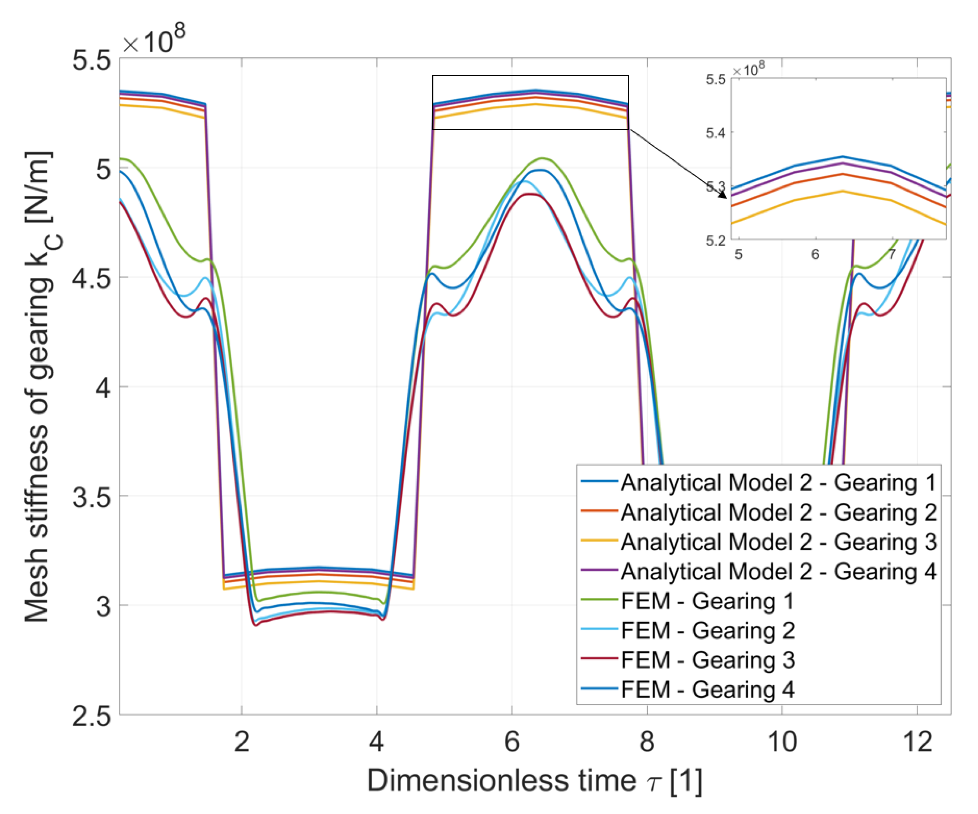
The
Figure 8 shows a different situation. The results of the AM2 method are significantly closer to the FEM method. This can be seen from the
Table 5. The theoretical model (AM2) represents individual gears stiffer compared to the FEM method too, but values of stiffnesses of single pair of teeth are significantly closer to the results of the FEM analysis. The theoretical (AM2) and FEM stiffnesses of single pair of teeth differ by 4%. Values of stiffnesses of double pairs of teeth also approached the FEM model more than AM1. The stiffness of double pairs of teeth differs by 13%. Results of the AM2 can be attributed to the fact that this method better describes the actual shape of the tooth. When using AM2, there is also no problem of non-compliance with the initial conditions, as in the model AM1 in the calculation of the mesh stiffness of the Gearing 4. The comparison in the
Figure 8 shows that the stiffest gearing is the Gearing 1.
The Gearing 5 was intentionally non-standardly designed in order to see an extreme case, which is not suitable for analytical calculations in terms of the geometry of the tooth root. Teeth do not have a standard fillet radius to be clearly recognizable, which AM1 cannot describe. Furthermore, a large modulus and a small face width were chosen to make the teeth pliable and to better demonstrate the difference in the resulting values.
This results in a huge difference in the values of the theoretical(AM1) and FEM stiffness of the gears during the contact of single pair of teeth and double pairs of teeth. For stiffness of single pair of teeth, the theoretical and FEM calculations differ by up to 91.5%. For the stiffness of double pairs of teeth, this difference is 65.5%. The influence of the tooth profile, which is not standard in the case of Gearing 5, is considerably manifested, here. The large undercut of teeth and small fillet radius significantly reduce tooth stiffness.
When using the AM2 method, the results are also not ideal as in the case of the Gearing 1–4, but they are still significantly better than results of AM1. For stiffness of single pair of teeth, the theoretical and FEM calculations differ by up to 54.9%. For the stiffness of double pairs of teeth, this difference is 9.8%.AM2 has made it possible to include the geometry of a specific Gearing 5. However, non-standard tooth geometry is still better to avoid and to design standard gearing. Despite the fact that the values of single and double-pair mesh stiffnesses are significantly closer to the results of the FEM simulation, the shape of the stiffness curve is still very different and it can be seen how this unusual shape manifests itself during the FEM calculation.
5. Conclusions
This article dealt with the topic of modeling the mesh stiffness of gear teeth. Two different methods of the analytical approach to modeling the course of mesh stiffness were presented on this issue. Both of these approaches, namely AM1 and AM2, were used to determine the mesh stiffness curves for the five designed gears (Gearing 1–5), due to which it was possible to make a final comparison. To evaluate the analytical model AM1 and AM2, stiffness modeling using FEM software Abaqus CAE was mentioned. Due to the software, mesh stiffness curves of Gearing 1–5 were also obtained. Therefore, it was possible to compare and evaluate analytical and FEM curves at the end.
From the
Section 4, it can be seen that AM1 supposes the gearing mesh stiffness to be higher than in the FEM stiffness calculation. There are more factors that may cause this fact.
- 1.
The theoretical approach of AM1 is based on empirical relationships based on the tested samples. Although the proposed Gearings 1–4 meet the initial conditions of the analytical calculation, the theory of AM1 itself allows the possibility of up to a 20% difference in values, which is fulfilled here.
- 2.
The FEM model considers only modeled gearing without a gear body. This can reduce the resulting FEM stiffness. However, the FEM model was created on the basis of the definition of the analytical model AM1, which also considers only gearing without a gear body to simulate the course of stiffness.
Gearing 5 clearly does not fit the AM1. This model has been introduced intentionally to show the lack of AM1. So the shape of the tooth profile at Gearing 5 is different from the standard profile, therefore this analytical method cannot be used.
Analytical model AM1 uses profile shift coefficients to determine the force arm. The profile shift coefficients are not intended to affect the exact shape of the fillet-foundation, therefore this analytical method is also distorting. For approximate calculations of mesh stiffness of gear with a standard profile, AM1 is a sufficient tool for determining mesh stiffness. However, for more accurate dynamic calculations, it would be more appropriate to use more precise analytical models, such as AM2 in this article.
This model (AM2) allows to include the exact geometry of the designed gearing and does not have limiting conditions like AM1. Due to calculations based on the deformation energy of the tooth, similar results as FEM analysis can be obtained with sufficient accuracy.
Another advantage of AM2 is that the resulting mesh stiffness curve can be used directly in the dynamic equations of gear transmission systems and unlike the AM1 method, does not affect the frequency spectrum as we avoid using the Fourier series to simulate the stiffness curve.


