Article

The UWB Radar Application in the Aviation Security Systems

Faculty of Aeronautics, Technical University of Kosice, 041 21 Košice, Slovakia
*
Author to whom correspondence should be addressed.
Appl. Sci. 2021, 11(10), 4556; https://doi.org/10.3390/app11104556
Submission received: 7 April 2021 / Revised: 4 May 2021 / Accepted: 11 May 2021 / Published: 17 May 2021

Abstract

:
In the process of our research, we have identified new methods of processing ultra-wide-band (UWB) radar signals and possibilities of the UWB radar use in aviation security systems. We paid our main attention to finding new algorithms for tracking the movement of a person behind an obstacle using the UWB radar. Such UWB radar application is typical for tracking the movement of people behind obstacles in case of security forces intervention at an airport. In the research process, we used methods of analysis, synthesis, and measured data from the performed experiment. The main contribution of the paper is the development of new algorithms for locating the movement of a person behind an obstacle using a straight- line method in the case of using two independent UWB radar systems. The article did not examine the accuracy of determining the position of a person behind the obstacle. We found that when applying the Kalman filter after signal processing by the straight-line method, the trajectory of the person’s movement behind the obstacle was smoother. The results of processing the measurement signals of UWB radar by the linear method have shown that this method is applicable to tracking a person behind an obstacle and can be used in aviation security systems.

1. Introduction

The International Air Transport Association (IATA) emphasizes that security and safety are key priorities for IATA and its member airlines. IATA calls on governments to continue working with the aviation industry to develop appropriate measures for current emerging trends. While IATA recognizes that aviation security is the responsibility of governments and that industry must meet the needs of competent authorities to act immediately in the event of an imminent security threat or vulnerability, it also considers it an effective partnership between the government and industry making the air transport system the safest and most secure form of long-distance travel [1]. Therefore, it is very timely to address the challenges of increasing aviation security using UWB technology. In recent years, there has been a relatively large demand for the development of UWB sensor systems. These systems are used in the field of non-destructive testing and in industrial areas [2,3,4,5,6]. In specific applications, UWB sensor systems are used as Ground Penetrating Radar [6,7], to locate and search for people behind obstacles and walls [8,9], to locate general objects or robots [10], in the field of non-invasive diagnostics and detection in medicine [11,12,13], and also in the automotive industry [14]. They are heavily involved in the development of frequently discussed solutions called Internet of Things and Industry 4.0. UWB devices have a wide application. In [15], the authors present the possibilities of creating algorithms for processing UWB radar signals in the case of detection and localization of static people and monitoring of basic parameters of their vital functions. The author of [16] presents hardware components of UWB radars, methods of processing UWB radar signals, and selected applications of these UWB systems in the field of security and medicine. The authors of [17] describe UWB technology for locating and tracking the robot behind obstacles in an industrial environment. The developed UWB radar signal processing algorithms make it possible to improve the tracking of targets in a complex industrial environment, which will contribute to the safe orientation of the robot in this environment. In [18], the possibilities of tracking moving persons by UWB radars are analyzed, and a comprehensive description of the effect of mutual shielding of persons is given. The authors also present three possible approaches to suppress the impact of this effect and increase the accuracy of tracking moving people. The authors of [19] present algorithms for processing UWB radar signals in tracking static and moving people. Using the experiment, the authors verified the possibility of tracking a moving person behind an obstacle formed by the wall of the building. In [20], the authors presented a new approach to target localization, which is based on the addition and combination of time of arrival algorithms (TOA) in combination with a conventional method of direct calculation. The created algorithms were verified for the localization of one moving person behind the wall. In [21], a synthesis of algorithms for human motion recognition using UWB technology was performed. The created algorithms enable the recognition of the movement of several people. These algorithms were tested on a sample of 15 people. The authors state that the accuracy of determining the motion parameters was 97%. In [22], a synthesis of the tracking system of persons was performed based on the use of information from the inertial navigation system and the UWB system. Such a comprehensive tracking system achieves 85% less error in determining a person’s position compared to an inertial navigation system. At present, much attention is being paid the ultra-wideband (UWB) multi-input multi-output (MIMO) radar technique, which plays an important role in the application of through-wall detection due to its high resolution and efficient data recording. The authors of [23] propose providing UWB with a multi-input multi-output radar system for through-wall imaging using a cross correlation-based time domain back projection algorithm (TDBP). The results of the experiments presented in this work demonstrate that the proposed imaging methods in the range and in azimuth can effectively suppress artifacts and focus on various targets, and the designed MIMO radar system can detect and locate human targets behind the wall [23]. The paper [24] presents a proposal of a MIMO radar system using the compensation method based on the reference channel, and a modified algorithm for displaying reverse Kirchhoff migration is proposed. The modified reverse Kirchhoff migration imaging algorithm has smaller lateral lobes compared to the traditional 3D backward projection algorithm. The proposed MIMO radar system can be used for real-time high-precision 3D through-wall radar imaging of multiple moving targets [24]. We have published some research results in the field of UWB radar signal processing and their application in practice in [25,26,27,28]. The document [26] states that the good penetration ability of UWB signals through most of the materials enables the detection of objects hidden behind walls and other obstacles. In [27], we deal with selected stages of UWB radar signal processing. We present the definition of UWB, as well as some of the phases of the UWB radar signal processing. Next, the procedures of preliminary data processing and ways of static background subtraction are described. In [28], we present the possibilities of background elimination. The purpose of eliminating the background is to increase the signal-to-noise ratio at the received data following preliminary processing. Procedures of the background subtraction can help remove the stationary clutter such as the antenna feed-back and clutters caused by impedance inadaptability. In [29], we present the selected stages of radar signal processing, the information that can be obtained from them, and the errors in determining the target position. The main contribution of this paper consists of the development of algorithms for target location by way of finding the intersections of the ellipses in case of using two independent radar systems. The analysis of the current state of UWB technology in the field of tracking people behind the wall shows that this technology can be used at civil and military airports in the field of security. The published results in this area show that the created algorithms for processing the measurement signals of UWB radars enable sufficiently accurate tracking of people behind obstacles but require great demands on their practical implementation. Therefore, we were looking for new methods of processing UWB radar measurement signals, which would allow tracking the movement of a person behind an obstacle. Our priority was not the accuracy of determining a person’s location, but the ability to discover a person and track their movement behind the obstacle. This is one of the possible scenarios for security forces to intervene at the airport to search for or detain dangerous persons.

2. Materials and Methods

2.1. Localization of the Target by the Straight-Line Method for Two Independent Radar Sets

The radar data analyzed in this part of the work were obtained by UWB radars, which use a pseudo-random sequence-M. The use of pseudo-random code- M in UWB radars was first designed by Sachs and Peyerl (US patent No. 6272441, 1996). The main advantages of its use are as follows [30,31,32]:
The use of a periodic binary signal reduces non-linear distortion (spectral bias error);
Allows linear averaging to reduce (suppress) noise;
The sequence M has a low crest factor, which allows using limited dynamics of the real system;
Signal acquisition can be performed by sampling;
Signal sampling can be performed by commercial A/D converters in combination with sampling gates (switches).
High resolution and accuracy of distance measurement

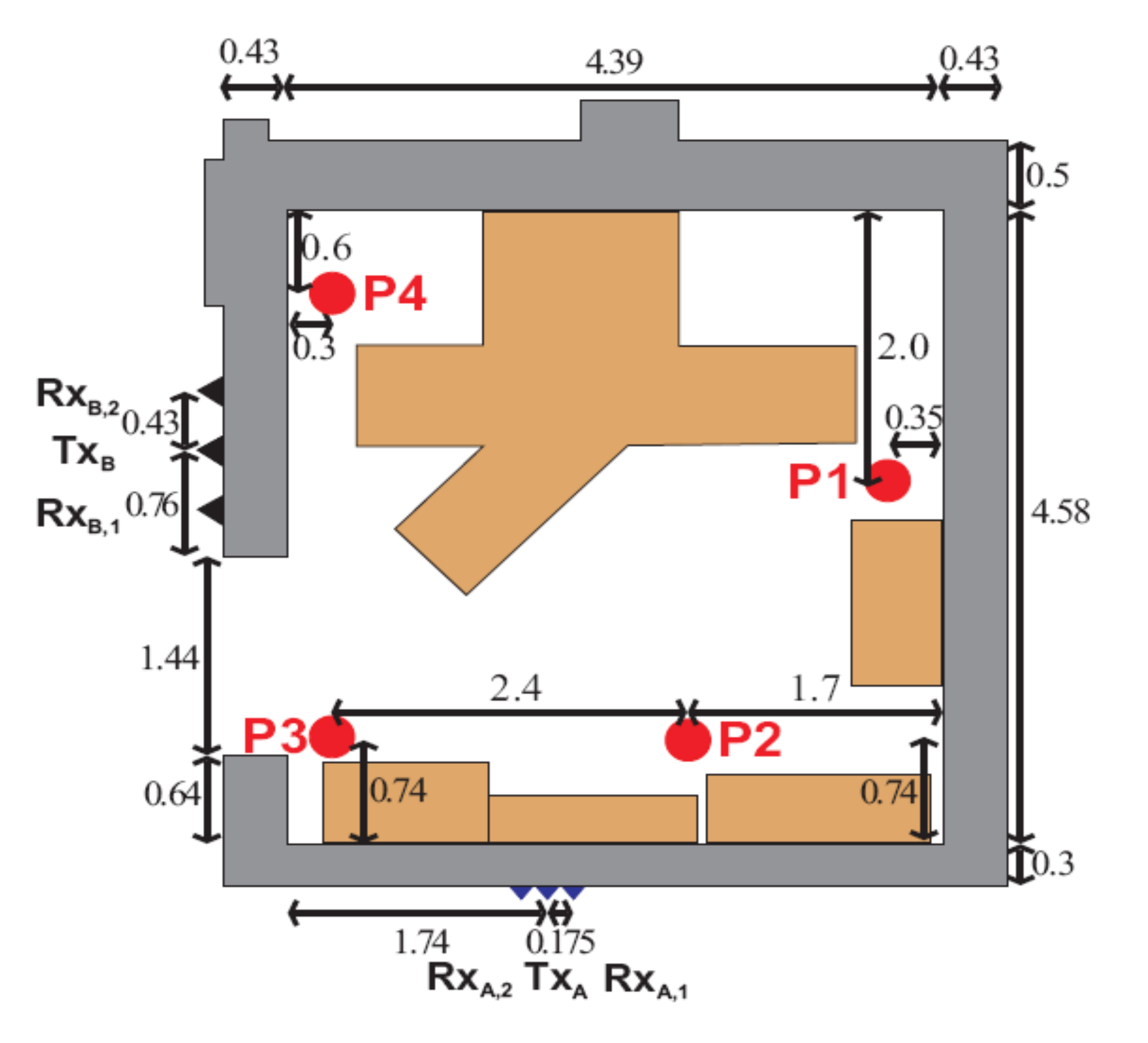
2.1.1. Description of the Place of the Experiment and the Target Movement

The movement of a person within the room behind a concrete obstacle is shown in Figure 1. The position of a moving person was determined by two independent UWB radar systems. Radar parameters are as follows [29]:
M-sequence UWB radar RS1
Radar clock frequency: 13 GHz; frequency bandwidth: 6.3 GHz; pulse response length in time: 4095 samples/315 ns; maximum range: 47 m; radiated power: 10 mW;
M-sequence UWB radar RS 2
Radar clock frequency: 4.5 GHz; frequency bandwidth: 2.25 GHz; pulse response length in time: 511 samples/114 ns; maximum range: 17 m; radiated power: 1 mW.
The antenna system of the 1st radar set (RS1), consisting of a transmitting antenna and two receiving antennas, was placed behind a 0.3 m thick wall. The transmitting antenna of the 1st radar set RS1 (TxA) was placed at the beginning of the selected coordinate system in the middle between the receiving antennas (RxA 1,2) placed symmetrically, at a distance of 0.175 m from the transmitter. The antenna system of the 2nd RS2 radar set, consisting of a transmitting antenna and two receiving antennas, was placed behind the 0.43 m thick wall. The transmitting antenna of the 2nd radar set RS2 (TxB) was placed at the height of 3.14 m behind the left wall rooms in the middle between the receiving antennas (RxB 1,2) placed symmetrically, at a distance of 0.43 m from the transmitter.
We determined the position of a person who moved from the position P1 to positions P2, P3, P4, and from P4 to the position P1. To obtain trace estimation as a sequence TOA, the radar signal processing steps are described in [29]. We divided the experiment and signal processing of UWB radars into the following stages: placement of the radar on the walls of the room according to Figure 1; signal pre-processing, which includes synchronization setup, and deconvolution (see Section 2.1.2); target detection; target track estimate. In our paper, we describe the target track estimate in detail. The goal of localization is to determine the position of the target in a defined coordinate system by the usual method of locating targets, which consists [33] of the following steps. In the first step, an estimation of the distance between the target and a certain number of reference sensors is performed. Subsequently, using the distance estimation, the target position is estimated using the selected localization method. We used the principle of distance estimation to measure the time of arrival of the signal (Time of Arrival, TOA). TOA means the time interval between the transmission time and the signal reception time. The name is used for both One-Way Propagation Time (OWPT) and Round-Trip Propagation Time (RTPT) transmission [34]. In this case, the distance R between the target and the antenna is given by the product of half (1/2) of the signal propagation time and the signal propagation rate in the monitored environment. In our case, we used the bistatic configuration. Separate antennas for transmitting and receiving are at a certain distance from each other. The measurement makes it possible to construct an ellipse in 2D space (or an ellipsoid in 3D space) with focal points in the coordinates of the transmitting and receiving antennas. When locating a person, it is possible to determine their coordinates by finding the intersection of ellipsoids in 3D space. A condition for the functionality of TOA systems is the need for time synchronization between the target and the transmitting and receiving antennas in bidirectional RTPT transmission [34]. Since the transmitting antenna RS1 and the receiving antennas RxA 1,2 are close to each other, it is not a problem to ensure time synchronization between these antennas. Similar conclusions apply to the RS2, RxB 1,2 kit.

2.1.2. Pre-Processing of the UWB Radar Signal

In this contribution, we introduce the possibilities of the UWB radar application in the determining the position of people behind an obstacle. The UWB radar signal is processed in several stages [29,30]. The first task that needs to be solved in signal processing is pre-processing. At this stage, it is necessary to focus on eliminating or maximally suppressing the adverse effect of the radar itself on the received measurement signals. This phase of processing the radar signal with a pseudo-random M-sequence involves performing a correlation between the transmitted radar measurement signal and the received measurement signal. The procedure for pre-processing the received measurement signals was analyzed in [27]. In this work, we used the deconvolution method. Using this method can bring favorable results when tracking the location of multiple targets. The deconvolution task can be expressed as the process of obtaining an estimate of the actual primary output signal of the radar ĥ(t): ĥ(t) = deconvolution[hR(t)*hT(t)], where hT(t) the actual primary output of the radar and hR(t) are the impulse responses (excluding the response from the target) obtained by the measurement. The next phase in the processing of UWB radar measurement signals is background elimination. Our aim is to achieve the highest possible ratio of the power of the received useful signal to the noise after the pretreatment. Background subtraction algorithms are aimed at suppressing unwanted responses from targets, standing waves at the receiver input due to antenna mismatch, and false targets caused by reflections from the environment. These procedures allow us to detect moving targets. We analyzed the background reading methods in more detail in [18]. Which method we use for pre-processing the received measurement signals of the UWB radar and for reading the background depends on the nature of the task and the type of a signal used. Real-time operation is one of the most common requirements for processing received UWB radar measurement signals. We used the mentioned phases of UWB radar measurement signal processing in our research when determining the position of people behind an obstacle. Since the signals of UWB radars propagate through obstacles, we must consider the non-line-of-sight (NLOS) radio propagation and other interfering effects when processing these signals. Pre-processing of the data and suppression of the background are used to suppress these effects. These signal processing steps are described in [29,35]. When processing UWB radar signals from TxA and TxB transmitters, it is necessary to remove the background in these signals. For this purpose, it is appropriate to use the method of exponential averaging [35]. When subtracting the background, we proceed by determining the mean, median, or modus. We can use n previously received signals h(t, τ) to estimate the background ĥ(t, τ) [29]:
h ^ ( t , τ ) = E [ h ( t , τ ) ] r 1 r 1 + n , b ^ ( t , τ ) = median [ h ( t , τ ) ] r 1 r 1 + n .
If we use the exponential method of determining the mean value, then we use the previous estimate of the background b ^ (t, τ − 1) to determine it. We determine the actual background value b ^ (t, τ) using the following value of the function h(t, τ), using the relations:
b ^ ( t , τ ) = α b ^ ( t , τ 1 ) + ( 1 α ) h ( t , τ ) = b ^ ( t , τ 1 ) + ( 1 α ) [ h ( t , τ ) b ^ ( t , τ 1 ) ] = b ^ ( t , τ 1 ) + ( 1 α ) h B ( h , τ ) ,
where α is the scalar weight factor acquiring the values within (0 ÷ 1) and τ, denoting the actual time of observation. From Relation (1), it is clear that the new estimate includes information from the previous and actual estimate. Based on this, the previous estimate is emphasized, or frequent signal fluctuations are suppressed. In this way, it is possible to reveal the basic trends of background estimates. The value of the function hB(t, τ) for τ = cont. corresponds to a signal with the reduced background estimate. These signals represent reflections from moving targets. This method is suitable for real-time signal processing because it is relatively simple and does not require high memory requirements.

2.1.3. Principle of the Straight-Line Method

Even in the case of the use of two radar systems, where each set separately has its antennas located on one line, see Figure 1, it is possible to calculate unknown coordinate values (x, y) for the location of the target by the simple mathematical operations mentioned in [29] because part of the signal path ‖Tx → T → Rxi‖ is common for both receiving antennas of the proper set. The resulting relationships determined by this procedure allow separate calculations of the intersections of the ellipses located in the observation area for each of the radar sets. In the real case, these are two different values. Another possibility of calculating the intersections of ellipses is possible using the Bézout theorem. The principle of determining the intersections of ellipses and the algorithm for determining the intersections of ellipses using the Bézout theorem is described in detail in [29] and [36,37,38]. Complex roots are excluded from the estimated positions x ¯ , y ¯ of the intersections of the ellipses. Some of the other values x ¯ , y ¯ may be excluded if they are not in the possible target area. The above calculation of the intersections of two ellipses is derived for arbitrarily lying ellipses. The presented method of lines is a method of direct calculation. From the point of view of the complexity of the calculation, it is also advantageous to choose the local coordinate system so that the transmitter antenna of one of the sets is placed at its beginning (see the description of the experiment site, Figure 1). We assume the location of targets by two independent UWB radar systems. Each set of radars is made up of one transmitter and two receiver antennae, lying on two mutually perpendicular lines (e.g., Figure 1). In this case, it is possible to calculate the target coordinates based on the known coordinates of the antennae. The coordinates of the intersections of the ellipses X12RS1(t) and Y12RS1(t) for the radar set RS1 are determined using the method of finding the intersections of the ellipses, which is described in (28):
X12RS1(t) = −((p11 · d12) − (p12 · d11))/((X11 · d12) − (X12 · d11)),
Y12RS1(t) = −((p11 + X12RS1(t) · X11)2X12RS1(t)2)0.5,
where d11 is the distance between the transmitter, the target, and the antenna of the first receiver of the RS1 kit; d12 is the distance between the transmitter, the target, and the antenna of the second receiver of the RS1 set; p11 = 0.5 (d211X211); p12 = 0.5 (d2 12X212); X11 and X12 are the coordinates of antennas of RS1 set receivers.
Using the method of direct Equations (3) and (4) finding the intersections of ellipses, we determine the intersections of the ellipses from the TOA times measured by the given set.
The results of determining the intersections of ellipses at the selected observation time τk are shown for the radar set RS1 in Figure 2 where the expression E1 RS 1 represents the ellipse No. 1 of the radar set RS1, with foci in the position of the transmitter TxA and in the position of the receiver RxA1 (see Figure 1). The analog expression E2 RS 1 represents the ellipse No. 2, the radar set RS1, with foci in the position of the transmitter TxA and in the position of the receiver RxA2. See Figure 2a. The dimensions of ellipses and location of UWB radars in Figure 2, Figure 3, Figure 4, Figure 5, Figure 6, Figure 7, Figure 8, Figure 9 and Figure 10 are in line with the description in Figure 1. The line drawn through the intersections of the ellipses represents the 1st line using the method of lines. See Figure 2b. The coordinates of the intersections of the ellipses X12RS2(t) and Y12RS2(t) for the radar set RS2 are determined using the method of finding the intersections of the ellipses as follows:
Y12RS2(t) = ((p22 · d21p21 · d22))/(d22(YTR2Y21) + d21(Y22YTR2)),
X12RS2(t) = (((p21 + Y12RS2(t)) · (YTR2Y21)) 2/d21 − (Y12RS2(t) − YTR2)2)0.5 + YTR2,
where d22 is the distance between the transmitter, the target, and the antenna of the second receiver of the RS2 kit; d21 is the distance between the transmitter, the target, and the antenna of the first receiver of the RS2 set; p22 = 0.5. (Y22 2Y 2TR2d 222); p21 = 0.5. (Y221Y 2TR2d 221); Y21 and Y22 are the coordinates of antennas of RS2 set receivers; YTR2 is the coordinate of antenna of RS2 set transmitter. The results of determining the intersections of the ellipses at the selected observation time τK are shown for the radar set RS2 in Figure 3, where the expression E3RS2 represents ellipse No. 3 of the radar set RS2, with foci in the position of the transmitter TxB and in the position of the receiver RxB1.
The analog expression E4 RS 2 represents ellipse No. 4 in radar set RS2, with foci in the position of the transmitter TxB and in the position of the receiver RxB2. The line drawn through the intersections of the ellipses represents the 2nd line using the method of lines. The number of real intersections of ellipses in each of the investigated points was = 4. Other ellipse intersections can be found in this way. Finding the intersections of ellipses created by combinations of ellipses of different sets and their use is described in [29].
Let us investigate the mutual position of lines No. 1 and line No. 2, which we stated in previous paragraphs, at different times of observation (τ). As can also be seen in Figure 4 and Figure 5, in the observation area (room according to the above scenario), there is a straight line.
Vertical and horizontal lines in most positions (τ) intersect. The intersection of the lines connecting the intersections of the ellipses of the sets RS1 and RS2 is obtained by the least squares method [29,36]. Using this method, we estimate the vector p ^ = x   ^ y ^ T , which represents the unknown coordinates of the target according to the relation:
p ^ = ( A T   · A ) 1 · A T   · b
where
A = X 11   ·   d 12 X 12   · d 11 Y 11   ·   d 12 Y 12   · d 11 d 22 · ( X T R 2   X 12   ) + d 21 · ( X 22   X T R 2   )   d 22 · ( Y T R 2   Y 12     ) + d 21 · ( Y 22   Y T R 2     )   , b = p 11   ·   d 12 + p 12 · d 11   p 22 · d 21   p 12   · d 22 ,
where XTR2 represents the coordinates of antennas of the RS2 set transmitter.
The intersection of the lines connecting the intersections of the ellipses of the sets RS1 and RS2 is shown in Figure 6.
In the case of an existing sufficient number of real intersections of already mentioned lines, it is possible to create a trajectory of the target movement by the procedure introduced. The use of the method of direct calculation (finding the intersections of ellipses) has its limitations. It can be used if the ellipses have a common focus in the foci with the antennas Tx, Rx1. The advantage is also the placement of the antennas on one line. In the case of the use of two radar sets, these conditions are usually not met for practical reasons.

2.1.4. Application Procedure for the Straight-Line Method Usage

In the case of using two radar sets in positions, as shown in the scenario (see Section 2.1.1 and Figure 1), there are also other real intersections created by combinations of ellipses of different sets. Possible combinations are as follows:
For the intersections of the ellipses E1 RS 1 and E3 RS 2 in Figure 7a (the designation is the same as in Figure 2 and Figure 3), it is possible to connect them by a straight line. The line drawn by the intersections of the ellipses will represent the 3rd line of a straight-line method. Similarly, the intersections of the ellipses E1 RS 1, E4 RS 2 in Figure 7b, and the line drawn by them, are called the 4th line of the straight-line method.
By analogy, the lines drawn by intersections E2 RS1, E3 RS 2 in Figure 8a and E2 RS1, E4 RS2 in Figure 8b are referred to as the 5th and 6th line of the straight-line method in that order. For calculation of the combined intersections of the ellipses (shown in Figure 7 and Figure 8), it is possible to use the Bézout theorem, which does not impose restrictions on the location of the foci of ellipses.

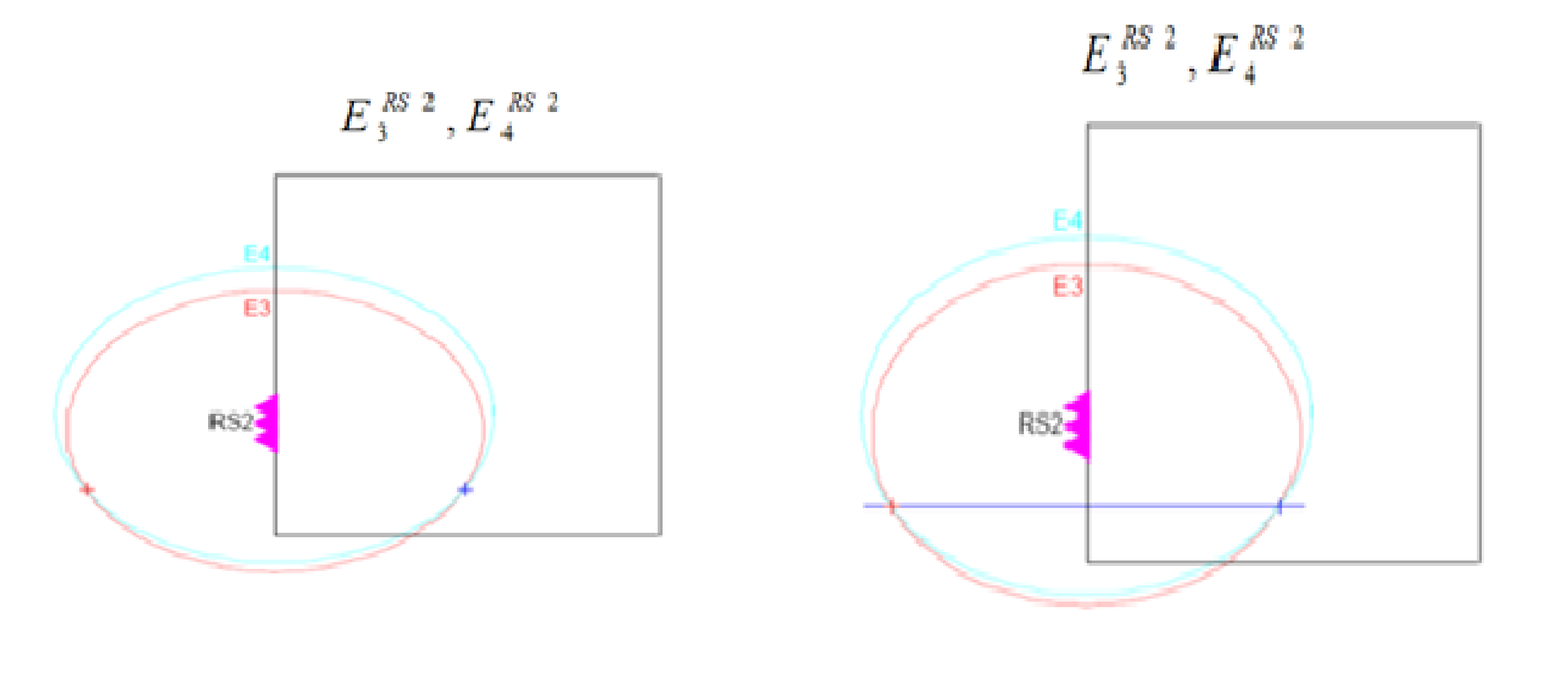
Algorithm for Determining the Intersections of Ellipses Using the Bézout Theorem

Calculation of coefficients of matrix A, vector b, and constant c for ellipses i. Consider two ellipses E1 and E2 defined by focal points F 1 i = x 1 i , y 1 i and F 2 i = x 2 i , y 2 i   major half-axes a 1 , a 2 determined by quadratic equations:
Q i p = p T A i p + b i T p + c i = x y × a 00 i a 01 i a 01 i a 11 i × x y + b 0 i b 1 i × x y + c i = 0 ,
where
a 00 i = ( x 1 i x 2 i ) 2 4 a i 2 , a 01 i = x 1 i x 2 i y 1 i y 2 i a 11 i = ( y 1 i y 2 i ) 2 4 a i 2 , b 0 i = x 1 i x 2 i ( 4 a i 2 ( x 1 i ) 2 ( y 1 i ) 2 + + ( x 2 i ) 2 + y 2 i ) 2 + 8 a i 2 x 2 i b 1 i = y 1 i y 2 i ( 4 a i 2 ( x 1 i ) 2 ( y 1 i ) 2 + + ( x 2 i ) 2 + y 2 i ) 2 + 8 a i 2 y 2 i c i = 1 4 ( 4 a i 2 ( x 1 i ) 2 ( y 1 i ) 2 + ( x 2 i ) 2 + + y 2 i ) 2 4 a i 2 ( x 2 i ) 2 4 a i 2 ( y 2 i ) 2 .
Calculation of auxiliary coefficients v 0 to v 10 :
v 0 = 2 a 00 0 a 01 1 a 00 1 a 01 0 , v 1 = a 00 0 a 11 1 a 00 1 a 11 0 , v 2 = a 00 0 b 0 1 a 00 1 b 0 0 , v 3 = a 00 0 b 1 1 a 00 1 b 1 0 , v 4 = a 00 0 c 1 a 00 1 c 0 , v 5 = 2 a 01 0 a 11 1 a 01 1 a 11 0 , v 6 = 2 a 01 0 b 1 1 a 01 1 b 1 0 , v 7 = 2 a 01 0 c 1 a 01 1 c 0 , v 8 = a 11 0 b 0 1 a 11 1 b 0 0 , v 9 = b 0 0 b 1 1 b 0 1 b 1 0 , v 10 = b 0 0 c 1 b 0 1 c 0 .
Calculation of coefficients u 0 to u 4 for Bézout’s determinant
u 0 = v 2 v 10 v 4 2 , u 1 = v 0 v 10 + v 2 v 7 + v 9 2 v 3 v 4 , u 2 = v 0 v 7 + v 9 + v 2 v 6 v 8 v 3 2 2 v 1 v 4 , u 3 = v 0 v 6 v 8 + v 2 v 5 2 v 1 v 3 , u 4 = v 0 v 5 v 1 2 .
Calculation of coordinates-y:
Calculation of polynomial roots R y = 0 ,
y s u r = r o o t s u 4 , u 3 , u 2 , u 1 , u 0 .
Selection of real roots of the equation and elimination of multiple roots y
i f _ i m a g y _ s u r i = 0 , y _ s u r _ r e a l = y _ s u r i , y _ s u r _ r e a l _ u n = u n i q u e y _ s u r _ r e a l , y _ r u = y _ s u r _ r e a l _ u n .
Calculation of coordinates x:
Calculation of coefficients of equations
Q i x , y , i = 1 , 2 z 0 = a 11 i ( y _ r u ) 2 + b 1 i y _ r u + c i , z 1 = 2 a 01 i y _ r u + b 0 i , z 2 = a 00 i .
Calculation of roots of equations:
Q i x , y , i = 1 , 2 x s u r = r o o t s z 2 , z 1 , z 0 .
Selection of real roots of the equation and elimination of multiple roots x
i f _ i m a g x _ s u r i = 0 x s u r r e a l = x s u r i x s u r r e a l u n = u n i q u e x s u r r e a l x _ r u = x _ s u r _ r e a l _ u n .
In the examined cases of calculation in each individual case (after elimination of imaginary and multiple), two real intersections remained. The position of lines No. 3, 4, 5, and 6 at the time of observation (τ = 100) is shown in Figure 9.

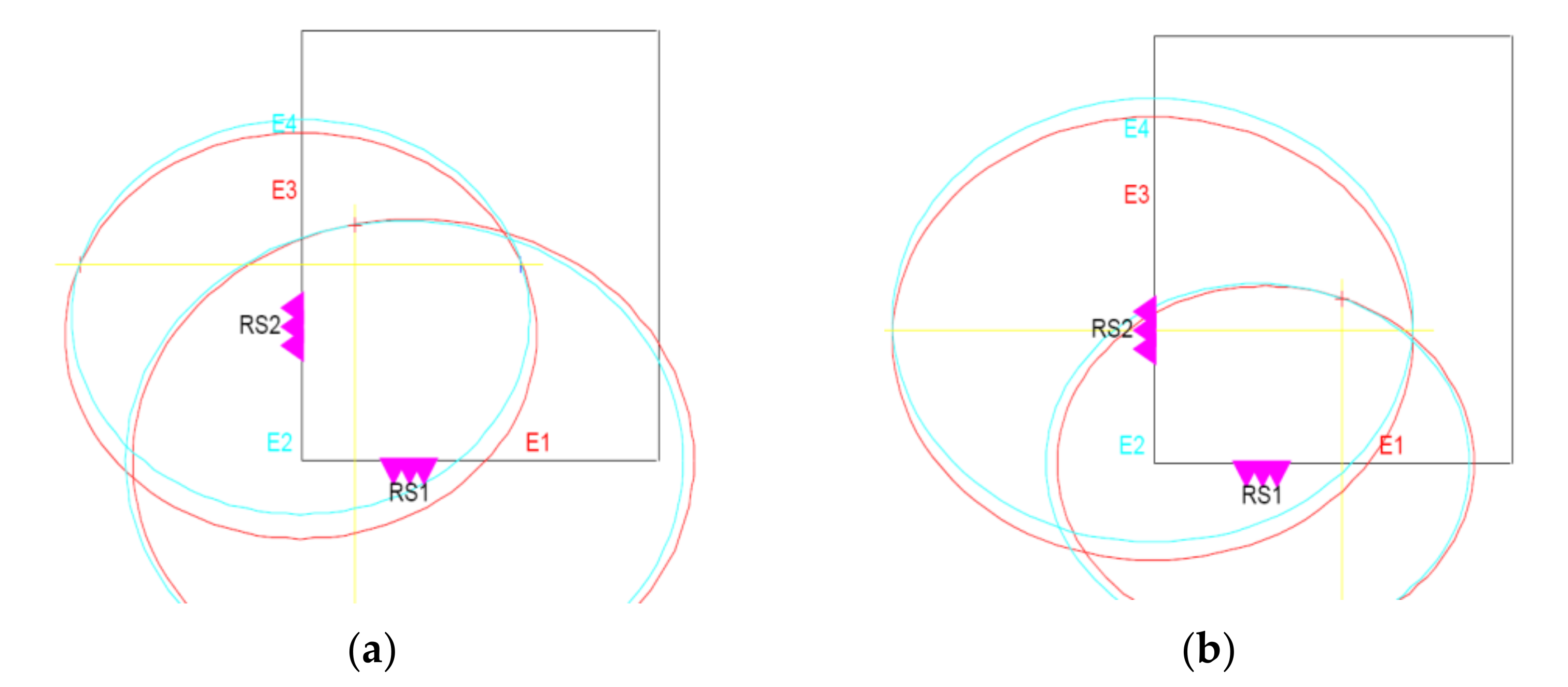
Creating an Optimal Line

n pairs of x i , y i , i = 1 , 2 , n , values of equal accuracy (weight) ( n > 2 ) ,
which should satisfy the equation y = a x + b   of the alignment line [28,29]
were measured. The substitution of
a x + b y = v i
after fulfilling the condition:
v v m i n
coefficients a , b are determined from the equations:
n b + a x = y b x + a x x = y x .
From the above relations, it is possible to create the optimal (straight) line shown in Figure 10. From the conclusions of the study of the course of pairs of ellipses, created by combinations of ellipses of different sets at selected moments (times) of observation (τ), it is clear that a group of intersections was formed inside the observation area (partially visible in Figure 7, Figure 8 and Figure 9), and the other group of intersections was formed outside the observation area. We will consider the first group as a realistic target.
Since the distribution of intersections of ellipses around the alignment line must be (due to the nature of the line) in the whole observed area similar to Figure 11, to determine the target point, it is appropriate to use the center of gravity of combined, real intersections of ellipses).

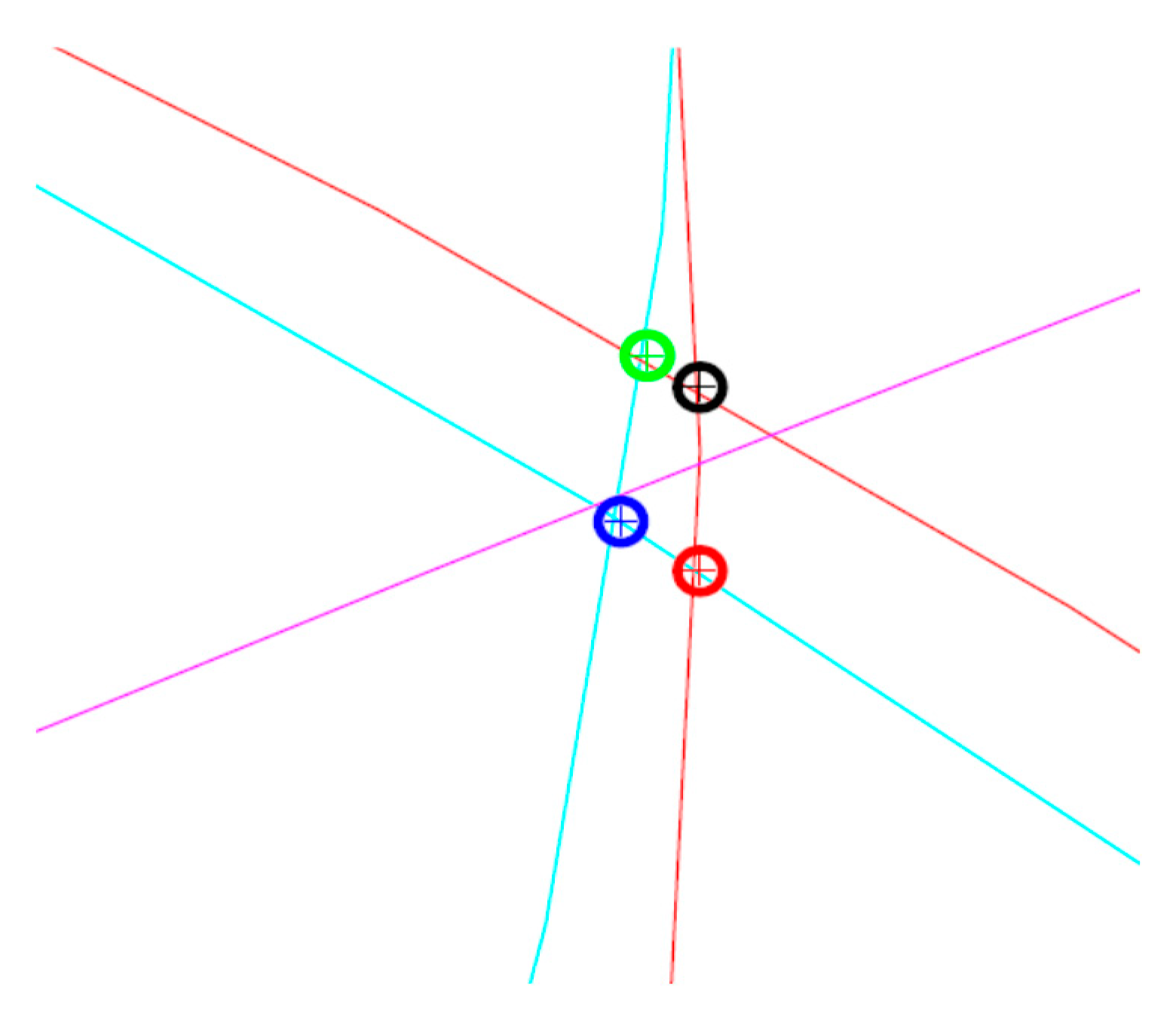
Calculation of the Center of Gravity of the Real Intersections of Ellipses

The intersections of ellipses created by a combination of two ellipses, each ellipse created by a different set RS, represent a potential target. I will mark the targets Tar1, Tar2 ... TarN. Calculation of the center of gravity of the real intersections of ellipses is listed in (28, 29):
Line direction:
k 1 = T a r N 2 1 , 2 T a r N 1 1 , 2 T a r N 2 1 , 1 T a r N 1 1 , 1 ) .
Line equations:
x p 1 = T a r N 1 1 , 1 : 0.1 : T a r N 2 1 , 1 ) , y p 1 = k 1 x p 1 T a r N 1 1 , 1 + T a r N 1 1 , 2 .
Line direction:
k N 2 = ( T a r N 1 , 2 T a r 1 1 , 2 T a r N 1 , 1 T a r 1 1 , 1 )     .
Line equations:
x p N 2 = T a r 1 1 , 1 : 0.1 : T a r N 1 , 1 ) , y p N 2 = k N 2 x p N 2 T a r 1 1 , 1 + T a r 1 1 , 2 .
Calculation of intersections of lines:
x g c = k 1 T a r N 1 1 , 1 + T a r 1 1 , 2 T a r N 1 1 , 2 k N 2 T a r 1 1 , 1 k N 2 + k 1 , y g c = k 1 x g c T a r N 1 1 , 1 + T a r N 1 1 , 2 .
In the absence of (or zero value) some targets (Tar), the position of the target is determined as the mean value of the remaining non-zero coordinates:
x g c = m e a n ( T a r N 1 , 1 , T a r N 1 1 , 1 T a r 1 1 , 1 , y g c = m e a n ( T a r N 1 , 2 , T a r N 1 1 , 2 T a r 1 1 , 2 .
Using Relations (19–24), we get the center of gravity of real intersections of ellipses. In Figure 11, the points of an intersection of ellipses (real targets) are marked by crosses in circles, and the alignment line is color-magenta.
Examples of the position of the center of gravity with respect to the alignment line (magenta) are shown in Figure 12. The center of gravity is marked with a cross in a green circle. The projection of the center of gravity point on the alignment line can be calculated using known relationships (21–23), e.g., applying the guideline k of the straight line.
In cases where the lines are marked as line No.1. and line No.2., the line methods (see Figure 4, Figure 5 and Figure 6), at the observed observation times (τ), are found in disproportionately distant positions from lines No. 3, 4, 5, and 6 and thus, they significantly distort the results of target localization; it is necessary to exclude them from the algorithm of the straight-line method.

3. Results

Results of the Application of the Straight-Line Method

The above procedure of localization of the target by the method of lines was applied to the real data ER_TU175_IL43. In order to determine the positions of the moving person, two independent UWB radar systems that use a pseudo-random sequence M were applied. The target was a person moving from position P (1), through positions P (2), P (3), P (4), again to position P (1).
The results of determining the position of a moving person are shown in Figure 13. The x and y coordinates in Figure 13 and Figure 14 are given in m. The results of processing measuring signals UWB radars showed that the created algorithms are suitable for locating the movement of a person behind an obstacle. From Figure 13, it is clear that the accuracy of identification is not very high, but it is sufficient for the purpose of identifying the person behind the obstacle. If a person moved from point P (1) to point P (2), his position would be determined with sufficient accuracy. When moving a person from point P (2) to point P (3), the errors in determining the position of the person were relatively large, but the determined trajectory of the person’s movement was in accordance with the person’s movement behind the obstacle. There are errors in the specified trajectory of the person’s movement between points P (2) and P (3). When a person’s position is determined in front of an obstacle, similar results are obtained when determining the position of a person in moving from point P (3) to point P (4). Figure 13 shows the parts of the person’s movement not detected by radar when persons move from position P (4) to position P (1). To increase the accuracy of localization, we used the Kalman filter when processing the UWB radar signal by the above method. The result of the target localization procedure after the application of the linear Kalman filter is shown in Figure 14.
The results of determining the position of a person moving behind an obstacle after applying the linear Kalman filter show that the positioning accuracy has improved. Even in this case, the radar completely did not detect the movement of a person from position P (4) to the position P (1).

4. Discussion

The straight-line method was not verified for the accuracy of determining the position of a person behind the obstacle, because the measured data were not synchronized with the exact position of the person during the measurement. Our goal was to develop an algorithm that would allow tracking the movement of a person behind an obstacle. Determining the exact position of a moving person was not our main goal, because we did not have the measured data for it. In UWB radar safety applications, we generally do not require high accuracy to determine the position of a person behind the obstacle. It is required to detect the presence of a person behind the obstacle and the direction of his/her movement. As follows from the description of our experiment, the position of a person behind a wall is determined by the rangefinder–rangefinder method. To determine the position of a person behind the wall, two independent radar systems are used, which we have designated as RS1 and RS2; see Figure 1. If we measure the distance of a person behind the wall from the receiving antennas of radars RS1 and RS2 and at the same time we know the coordinates of the antennas, then we can determine the position of the person. In this case, we will use the rangefinder–rangefinder method. If we denote the value of the linear error of the position line of the RS1 system by the symbol δ1 and the value of the linear error of the position line of the RS2 system by the symbol δ2, then we express the error of determining the position of the person Δl as follows:
Δl = (sin γ)−1 · [δ21 + δ22 + 2δ1 · δ2 · cosγ]0.5,
where γ is the angle between the position lines RS1 and RS2. The position line of the RS1 system is a circle with the center at the point of location of RS1 and of the radius determined by the distance the antenna RS1 from the position the person. The position line of the RS2 system is a circle with the center at the point of location of RS2 and of the radius determined by the distance of the antenna RS2 from the position of the person. From Relation (25), it is clear that the accuracy of determining the position of a person by such a system depends on the accuracy of measuring the distance (parameter δ1, δ2) and the position of the person relative to RS1 and RS2 (parameter γ). In our case, if the errors of the measured distances between the systems RS1 and RS2 and the moving person are large and the angle γ is different than 90 degrees, then the position of the person is determined with a large error. This makes it possible to explain the errors in determining the position of a person moving behind the obstacle. The application of the linear Kalman filter effectively has suppressed these errors.

5. Conclusions

In our work, we present a new method for location of the person’s movement behind the obstacle using the UWB radar, which we called the straight-line method. This method is fairly accurate and allows determining the position of the person behind the obstacle using UWB radars. It uses the intersections of the ellipses created by each radar set as well as combinations of the intersections of the ellipses created by using two radar sets. In principle, the presented method of lines is a combination of the method of direct calculation and calculation using the Bézout theorem. The measurement results show that the UWB radar can be used to locate people in the houses. Obviously, the use of a radar is limited by the thickness of the obstacle behind which the person is positioned. From the technical data of UWB systems, which are given in Section 2.1.1. of this work, it is clear that these systems use a very wide frequency band for operation. The width of this band exceeds several frequency bands in the very high frequency range. UWB systems have a small range in most cases. This feature is due to the fact that the transmission of a very broadband signal is characterized by high energy consumption. Obviously, if we use smaller transmission powers; thus, the reduced range corresponds to this. The advantage of using lower power in UWB systems is the suppression of artificial interference that these systems can cause. This fact limits the interference to other systems operating in the same frequency band. It is clear from the analysis that UWB systems can be used as communication devices. Due to the possibility of tracking people behind obstacles, UWB systems can be used in security applications and in the military. Due to their accuracy, UWB systems can be used in transport. Recently, research into the use of UWB systems has focused on their application in medicine in the diagnosis of oncological diseases. UWB systems are characterized by the high resolution of targets that are close to each other. They can measure distance very accurately. Due to the large width of the frequency band, they are very resistant to interference. Therefore, research in the field of synthesis of UWB systems is focused on the creation of new algorithms enabling the processing of their signals under interference conditions. Typical examples of such interference are reflections on ships, buildings, or the propagation of measurement signals through walls. The new method of determining the coordinates of the goal, which we present in our paper, allows us to determine the coordinates of the goal behind the obstacle with sufficient accuracy. Therefore, this method of processing UWB radar signals can be used in the security applications of UWB systems. Our further research in the field of UWB radar signal processing will be focused on determining the coordinates of targets using two transmitting sensors in interference conditions. The straight-line method was not verified for the accuracy of determining the position of the person behind the obstacle because the measured data were not synchronized with the exact position of the person during the measurement. Our contribution is the design of a new method of processing radar signals UWB, which allows us to monitor the movement of a person behind the obstacle. Although this method of processing UWB radar signals is not more accurate than the methods presented in the introduction of this work, we can use it in security applications, where we do not require high accuracy of determining the position of a person behind an obstacle but only his/her identification. The advantage of this method is its use for processing UWB radar signals in real time.

Author Contributions

The co-authors had together contributed to the completion of this article. Specifically, it follows their individual contribution: M.D. and Z.C. equally contributed to writing original drafts, conceptualization, data collection and analysis, and methodology. P.D., P.K. (Peter Kaľavský), P.K. (Peter Korba), and M.H. contributed to the formal analysis and editing of the paper. All authors have read and agreed to the published version of the manuscript.

Funding

This research received no external funding.

Institutional Review Board Statement

Not applicable.

Informed Consent Statement

Not applicable.

Data Availability Statement

Not applicable.

Conflicts of Interest

The authors declare no conflict of interest.

References

  1. IATA, PROGRAMS, Aviation Security. 2021. Available online: https://www.iata.org/en/programs/security/ (accessed on 20 April 2021).
  2. Sachs, J. Ultra-wideband sensing: The road to new radar applications. In 11-th International Radar Symposium; IEEE: Piscataway, NY, USA, 2010; pp. 1–4. [Google Scholar]
  3. Silva, B.; Pang, Z.; Åkerberg, J.; Neander, J.; Hancke, G. Experimental study of UWB-based high precision localization for industrial applications. In 2014 IEEE International Conference on Ultra-WideBand (ICUWB); IEEE: New York, NY, USA, 2014; pp. 280–285. [Google Scholar] [CrossRef]
  4. Sachs, J.; Badstubner, A.; Bonitz, F.; Eidner, M.; Helbig, M.; Herrmann, R.; Kmec, M.; Rauschenbach, P.; Solas, H. High resolution non-destructive testing in civil engineering by ultra-wideband pseudo-noise approaches. In 2008 IEEE International Conference on Ultra-Wideband; IEEE: New York, NY, USA, 2008; pp. 137–140. [Google Scholar] [CrossRef]
  5. Iyer, B.; Pathak, N.P. Multiband Non-Invasive Microwave Sensor: Design and Analysis; CRC Press: Boca Raton, FL, USA, 2018. [Google Scholar]
  6. Galajda, P.; Pecovsky, M.; Gazda, J.; Drutarovsky, M. Novel M-sequence UWB sensor for ground penetrating radar application. In 2018 IEEE Asia-Pacific Conference on Antennas and Propagation (APCAP); IEEE: New York, NY, USA, 2018; pp. 110–111. [Google Scholar]
  7. Johansson, E.M.; Mast, J.E. Three-dimensional ground-penetrating radar imaging using synthetic aperture time-domain focusing. In Advanced Microwave and Millimeter-Wave Detectors; International Society for Optics a Photonics: Washington, DC, USA, 1994; Volume 2275, pp. 205–214. [Google Scholar]
  8. Amin, M.G. Through-the-Wall Radar Imaging; CRC Press: Boca Raton, FL, USA, 2010; 604p, ISBN 9781439814765. [Google Scholar]
  9. Kocur, D.; Novák, D.; Švecová, M. Multiple Person Localization Based on Their Vital Sign Detection Using UWB Sensor. In Microwave Systems and Applications; Goudos, S.K., Ed.; InTech: London, UK, 2017; pp. 399–422. [Google Scholar]
  10. Slovák, S.; Galajda, P.; Švecová, M.; Pečovský, M.; Kmec, M. Ultra-wideband wireless sensors for robot vision in industrial environments. In 2017 Progress in Electromagnetics Research Symposium-Fall (PIERS-FALL); IEEE: New York, NY, USA, 2017; pp. 1697–1702. [Google Scholar]
  11. Staderini, E.M. UWB radars in medicine. In IEEE Aerospace and Electronic Systems Magazine; IEEE: New York, NY, USA, 2002; Volume 17, pp. 13–18. [Google Scholar]
  12. Higashikaturagi, K.; Nakahata, Y.; Matsunami, I.; Kajiwara, A. Non-invasive respiration monitoring sensor using UWB-IR. In Ultra-Wideband, 2008. ICUWB 2008; IEEE: New York, NY, USA, 2008; Volume 1, pp. 101–104. [Google Scholar]
  13. Ali, M.S.; Shoumy, N.; Khatun, S.; Kamarudin, L.; Vijayasarveswari, V. Noninvasive blood glucose measurement performance analysis through UWB imaging. In 2016 3rd International Conference on Electronic Design (ICED); IEEE: New York, NY, USA, 2016; pp. 513–516. [Google Scholar]
  14. Qian, Z.; Wang, T.; Chen, J. Compatibility Studies of IMT System and Automotive Radar in the Frequency Range 24.5-25.5 GHz. In 2018 IEEE 18th International Conference on Communication Technology (ICCT); IEEE: New York, NY, USA, 2018; pp. 505–508. [Google Scholar]
  15. Kocur, D.; Švecová, M. Signal Processing for Monitoring of Static Persons Using UWB Sensors: A Survey. In IEEE MTT-S International Microwave Biomedical Conference 2019; Institute of Electrical and Electronics Engineers: New York, NY, USA, 2019; pp. 1–3. ISBN 978-1-5386-7396-6. [Google Scholar]
  16. Kocur, D. UWB Technology and its Applications, 1st ed.; IntechOpen: London, UK, 2019; 92p, ISBN 978-1-7898-5716-0. ISSN 2193-9411. [Google Scholar]
  17. Galajda, P.; Svecova, M.; Drutarovsky, M.; Slovak, S.; Pecovsky, M.; Sokol, M.; Kocur, D. Wireless UWB Sensor System for Robot Gripper Monitoring in Non-cooperative Environments. In Recent Advances in Intelligent Engineering. 14. Topics in Intelligent Engineering and Informatics: Volume Dedicated to Imre J. Rudas’ Seventieth Birthday; Springer: Cham, Switzerland, 2020; pp. 177–207. ISBN 978-3-030-14349-7. ISSN 2193-9411. [Google Scholar]
  18. Kocur, D.; Fortes, J.; Švecová, M. Multiple moving person tracking by UWB sensors: The effect of mutual shielding persons and methods reducing its impacts. Eurasip J. Wirel. Commun. Netw. 2017, 2017, 1–15. [Google Scholar]
  19. Kocur, D.; Novák, D.; Švecová, M. UWB radar signal processing for localization of persons with the changing nature of their movement. Sens. Transducers Sens. Electron. Instrum. 2016, 207, 50–57. [Google Scholar]
  20. Kocur, D.; Svecova, M. Time of Arrival Complementing Method for Cooperative Localization of a Target by Two-Node UWB Sensor Network. Radioengineering 2016, 25, 602–611. [Google Scholar]
  21. Mokhtari, G.; Zhang, Q.; Hargrave, C.; Ralston, J.C. Non-Wearable UWB Sensor for Human Identification in Smart Home. IEEE Sens. J. 2017, 17, 3332–3340. [Google Scholar] [CrossRef]
  22. Tian, Q.; Wang, K.I.; Salcic, Z. A Low-Cost INS and UWB Fusion Pedestrian Tracking System. IEEE Sens. J. 2019, 19, 3733–3740. [Google Scholar] [CrossRef]
  23. Hu, Z.; Zeng, Z.; Wang, K.; Feng, W.; Zhang, J.; Lu, Q.; Kang, X. Design and Analysis of a UWB MIMO Radar System with Miniaturized Vivaldi Antenna for Through-Wall Imaging. Remote Sens. 2019, 11, 1867. [Google Scholar] [CrossRef] [Green Version]
  24. Pan, J.; Ye, S.; Shi, C.; Yan, K.; Liu, X.; Ni, Z.; Yang, G.; Fang, G. 3D imaging of moving targets for ultra-wideband MIMO through-wall radar system. In IET Radar, Sonar & Navigation; John Wiley & Sons Ltd: Hoboken, NJ, USA, 2021. [Google Scholar] [CrossRef]
  25. Cséfalvay, Z.; Džunda, M. Ultra-wide band radar signal processing. In Proceedings of the ICMT 2013: International Conference on Military Technologies, Brno, Czech Republic, 22–23 May 2013; University of Defence: Brno, Czech Republic, 2013; pp. 1–7, ISBN 978-80-7231-918-3.3. [Google Scholar]
  26. Džunda, M.; Cséfalvay, Z.; Kotianová, N. Selected aspects of applying UWB (Ultra Wide Band) technology in transportation. In Informatics, Networking and Intelligent Computing; CRC Press/Balkema: Leiden, The Netherlands, 2015; pp. 177–181. ISBN 978-1-138-02678-0. [Google Scholar]
  27. Džunda, M.; Cséfalvay, Z. Selected metods of ultra-wide radar signal processing. In Advances in Marine Navigation: Marine Navigation and Safety of Sea Transportation; Taylor & Francis Group: London, UK, 2013; pp. 239–242. ISBN 978-1-138-00106-0. [Google Scholar]
  28. Džunda, M.; Cséfalvay, Z.; Kotianová, N. Target Localization by Method of Intersections of the Ellipses Using two UWB Radar Systems. In International Conference on Advanced Educational Technology and Information Engineering; Destech publications: Lancaster, PA, USA, 2015; pp. 697–706. ISBN 978-1-60595-245-1. [Google Scholar]
  29. Cséfalvay, Z. UWB Radar Applications in Safety Systems. Ph.D. Thesis, TUKE, Kosice, Slovakia, 2013. [Google Scholar]
  30. Fontana, R.J.; Foster, L.A.; Fair, B.; Wu, D. Recent Advances in Ultra Wideband Radar and Ranging. In Proc of the IEEE International Conference on Ultra –Wideband. Systems; IEEE: New York, NY, USA, 2007. [Google Scholar]
  31. Daniels, D.J. Ground Penetrating Radar, 2nd ed.; IEE Radar, Sonar, Navigation and Avionics Series; The Institution of Electrical Engineers: London, UK, 2004; 726p, ISBN 9780863413605. [Google Scholar]
  32. Rovňáková, J.; Švecová, M.; Kocur, D.; Nguyen, T.T.; Sachs, J. Signal processing for through wall moving target tracking by M sequence UWB radar. Int. Conf. Radioelektron. 2008, 18, 65–68. [Google Scholar]
  33. Gezici, S. A Survey on Wireless Position Estimation. Wirel. Pers. Commun. Int. J. 2008, 44, 263–282. [Google Scholar] [CrossRef]
  34. Švecová, M. Node Localization in UWB Wireless Sensor Networks. Ph. D. Thesis to the Dissertation Examination, Department of Electronics and Multimedia Communications, Technical University of Kosice, Kosice, Slovak Republic, December 2007. [Google Scholar]
  35. Piccardi, M. Background subtraction techniques: A review. In Proceedings IEEE International Conference on Systems, Man and Cybernetics; IEEE: New York, NY, USA, 2004; pp. 3099–3104. [Google Scholar]
  36. Fan, Q.; Sun, B.; Sun, Y.; Zhuang, X. Performance Enhancement of MEMS-Based INS/UWB Integrtion for Indoor Navigation Applications. IEEE Sens. J. 2017, 17, 3116–3130. [Google Scholar] [CrossRef]
  37. Eberly, D. Intersection of Ellipses; Geometric Tools, LLC: Melville, NY, USA, 2011. [Google Scholar]
  38. Škrášek, J.; Tichý, Z. Základy Aplikované Matematiky I, II, III; SNTL: Praha, Czech Republic, 1983. [Google Scholar]
Figure 1. Deployment of radar systems and movement of the target in the building.
Applsci 11 04556 g001
Figure 2. Intersections of RS1 ellipses.
Applsci 11 04556 g002
Figure 3. Intersections of RS2 ellipses.
Applsci 11 04556 g003
Figure 4. Position of lines of RS1 and RS2 sets in the points (a) τ = 55 and (b) τ = 100.
Applsci 11 04556 g004
Figure 5. Position of lines of RS1 and RS2 sets in the points (a) τ = 150 and (b) τ = 225.
Applsci 11 04556 g005
Figure 6. The intersection of the lines joining the intersections of the ellipse RS1 and RS2 sets in the point τ = 150.
Applsci 11 04556 g006
Figure 7. Combined intersections of ellipses: (a) E1 sets RS1 and E3 sets RS2 and (b) E1 sets RS1 and E4 sets RS2.
Applsci 11 04556 g007
Figure 8. Combined intersections of ellipses: (a) E2 sets RS1 and E3 sets RS2 and (b) E2 sets RS1 and E4 sets RS2.
Applsci 11 04556 g008
Figure 9. Lines No. 3, 4, 5, and 6 guided by the intersections of ellipse sets RS1 and RS2 in the point τ = 100.
Applsci 11 04556 g009
Figure 10. Optimal line guided by the intersections of ellipse RS1 and RS2 sets in the point τ = 100.
Applsci 11 04556 g010
Figure 11. The alignment line and distribution of realistic targets at the point τ = 100.
Applsci 11 04556 g011
Figure 12. Examples of center of gravity point positions for (a) τ = 50 and (b) τ = 100.
Applsci 11 04556 g012
Figure 13. The trajectory of movement of the observed person after application of the straight-line method localization.
Applsci 11 04556 g013
Figure 14. The trajectory of movement of the observed person after application of the straight-line method localization and linear Kalman filter.
Applsci 11 04556 g014
Publisher’s Note: MDPI stays neutral with regard to jurisdictional claims in published maps and institutional affiliations.

