Stability Assessment of Current Controller with Harmonic Compensator for LCL-Filtered Grid-Connected Inverter under Distorted Weak Grid


Abstract
:1. Introduction
- (1)
- The two typical current controllers with harmonic compensators for the LCL-filtered grid-connected inverter are implemented to analytically investigate their performances under distorted weak grid by means of the stability assessment tools and comprehensive evaluation results.
- (2)
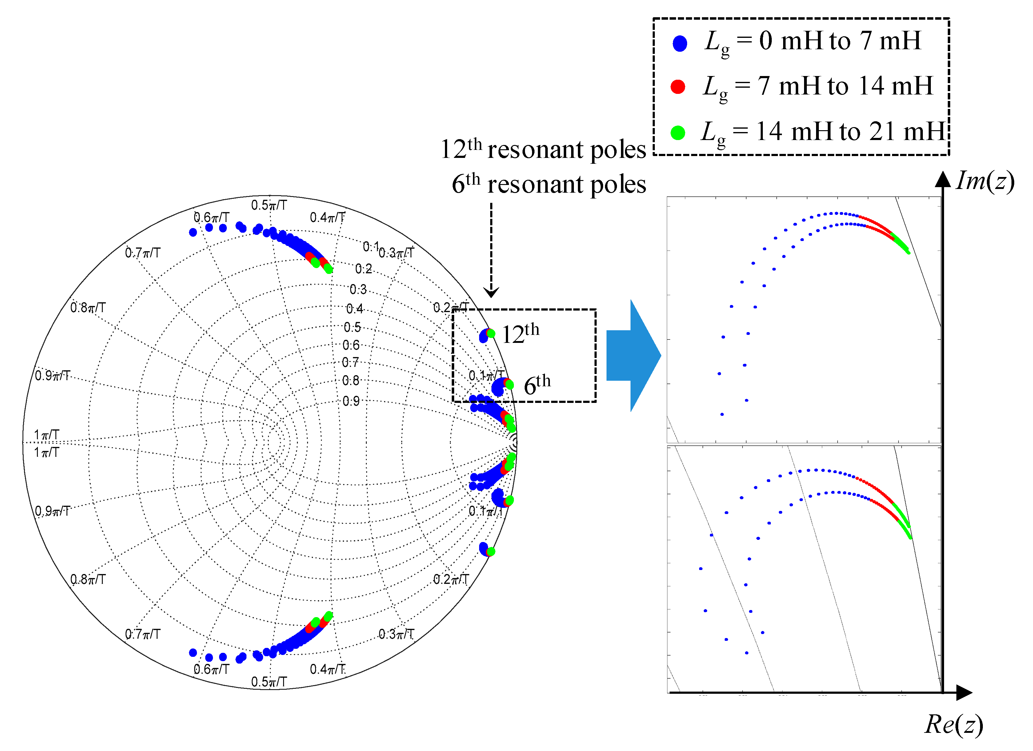
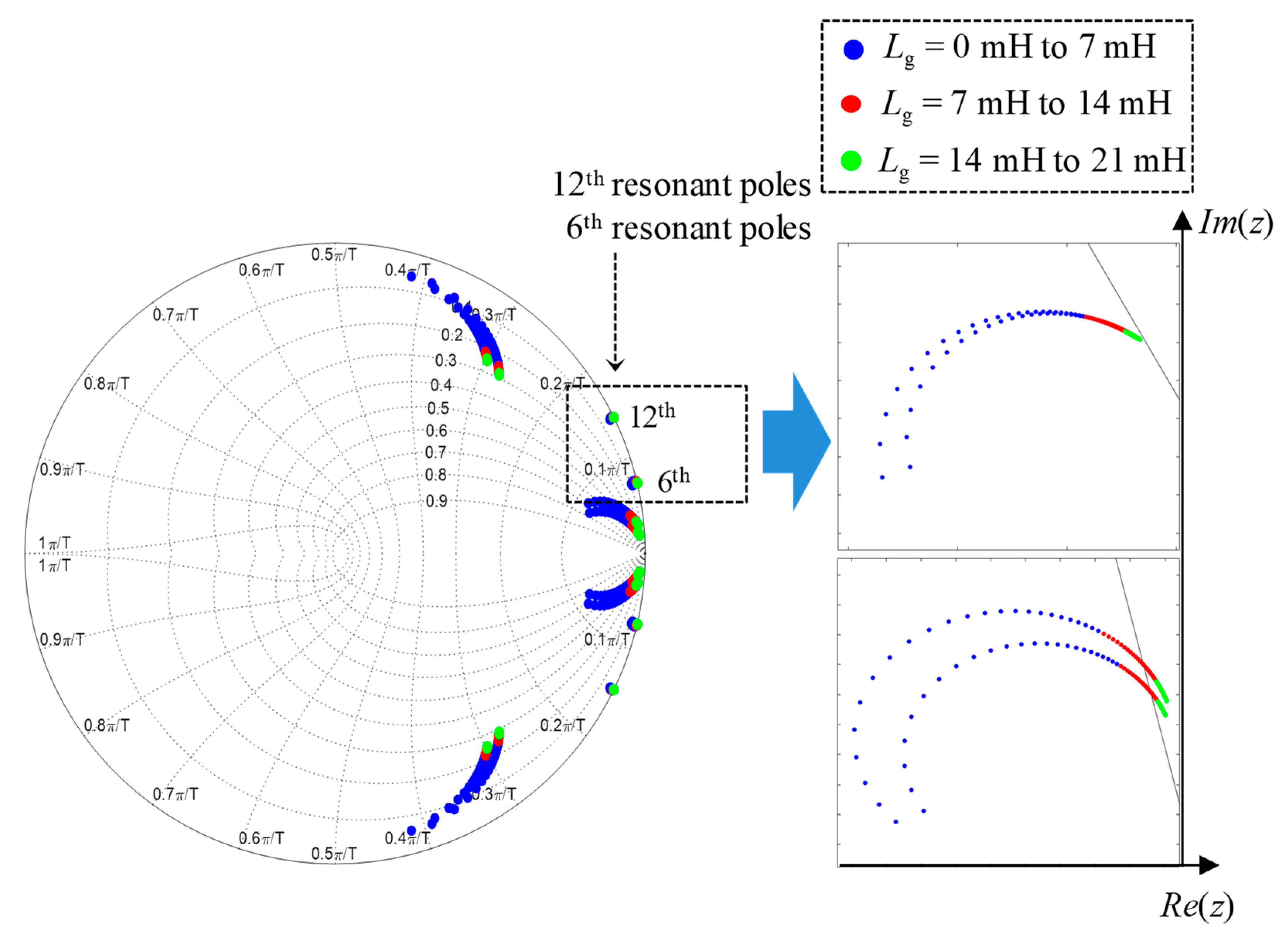
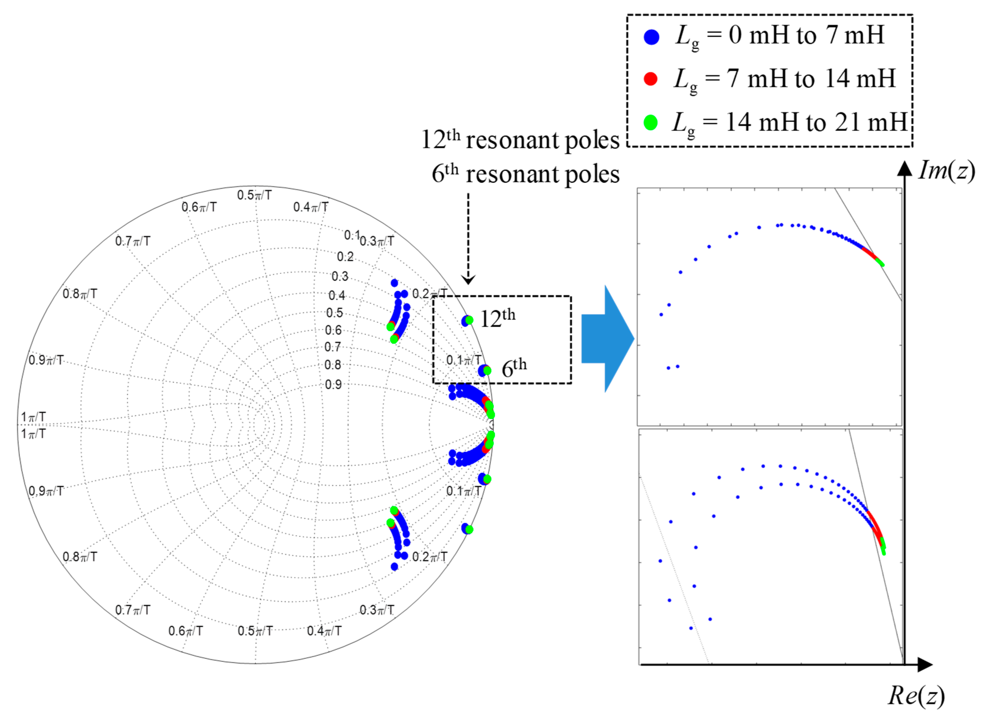
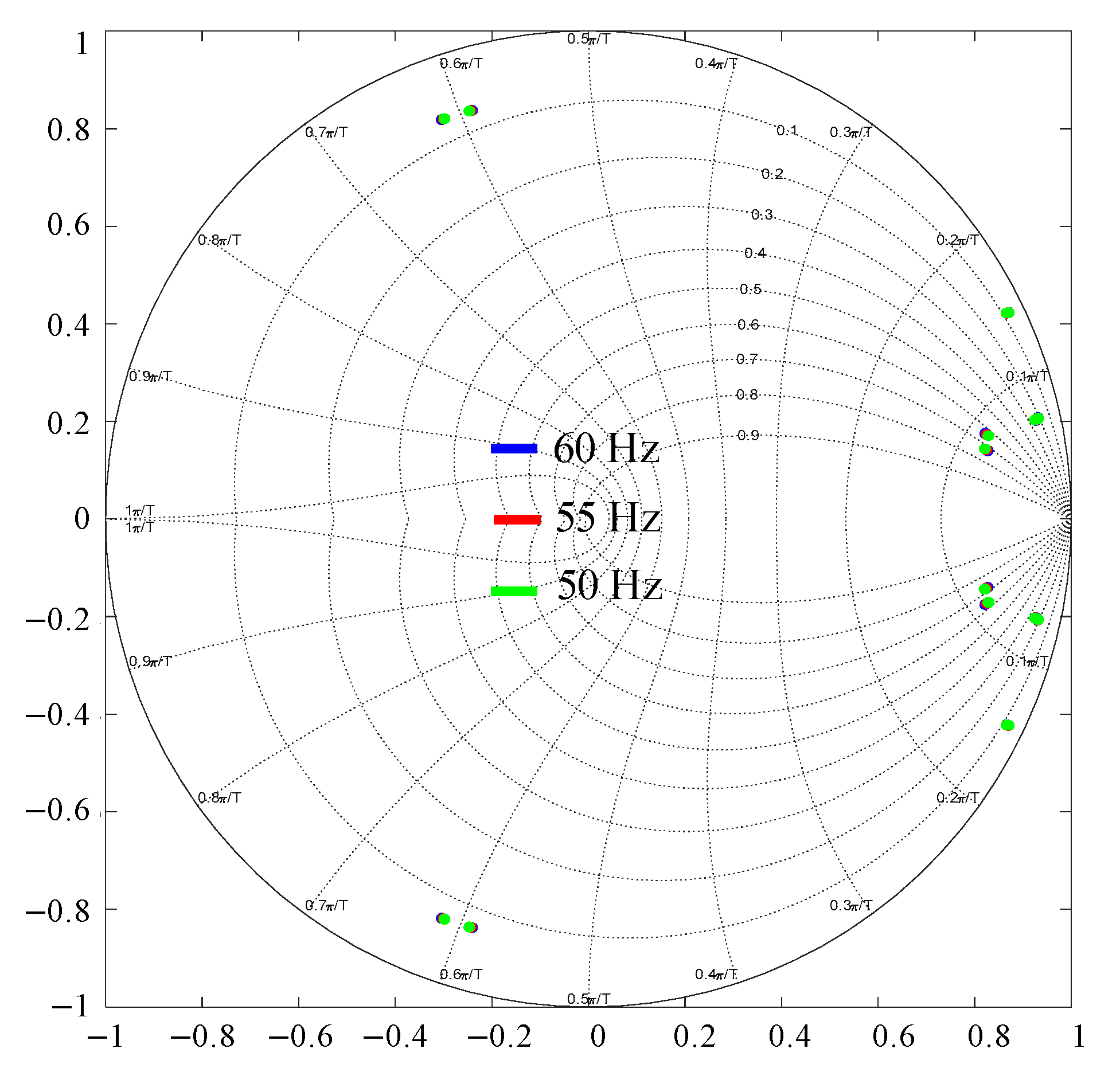
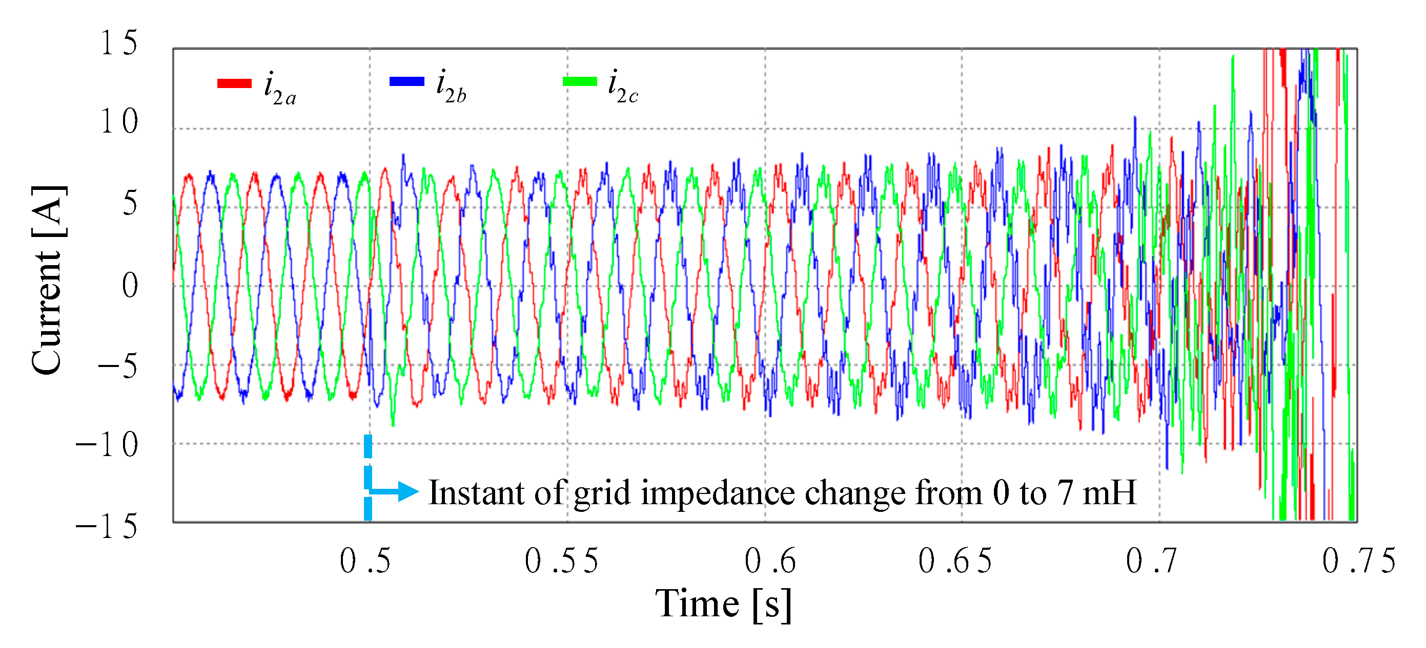
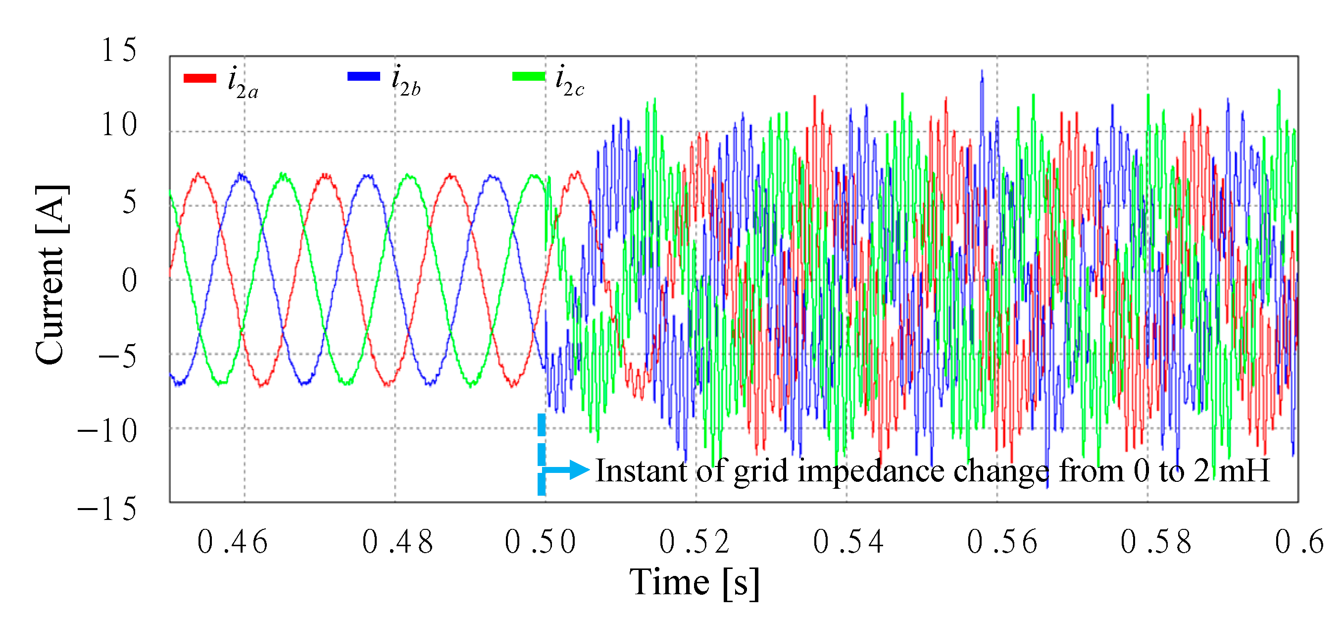
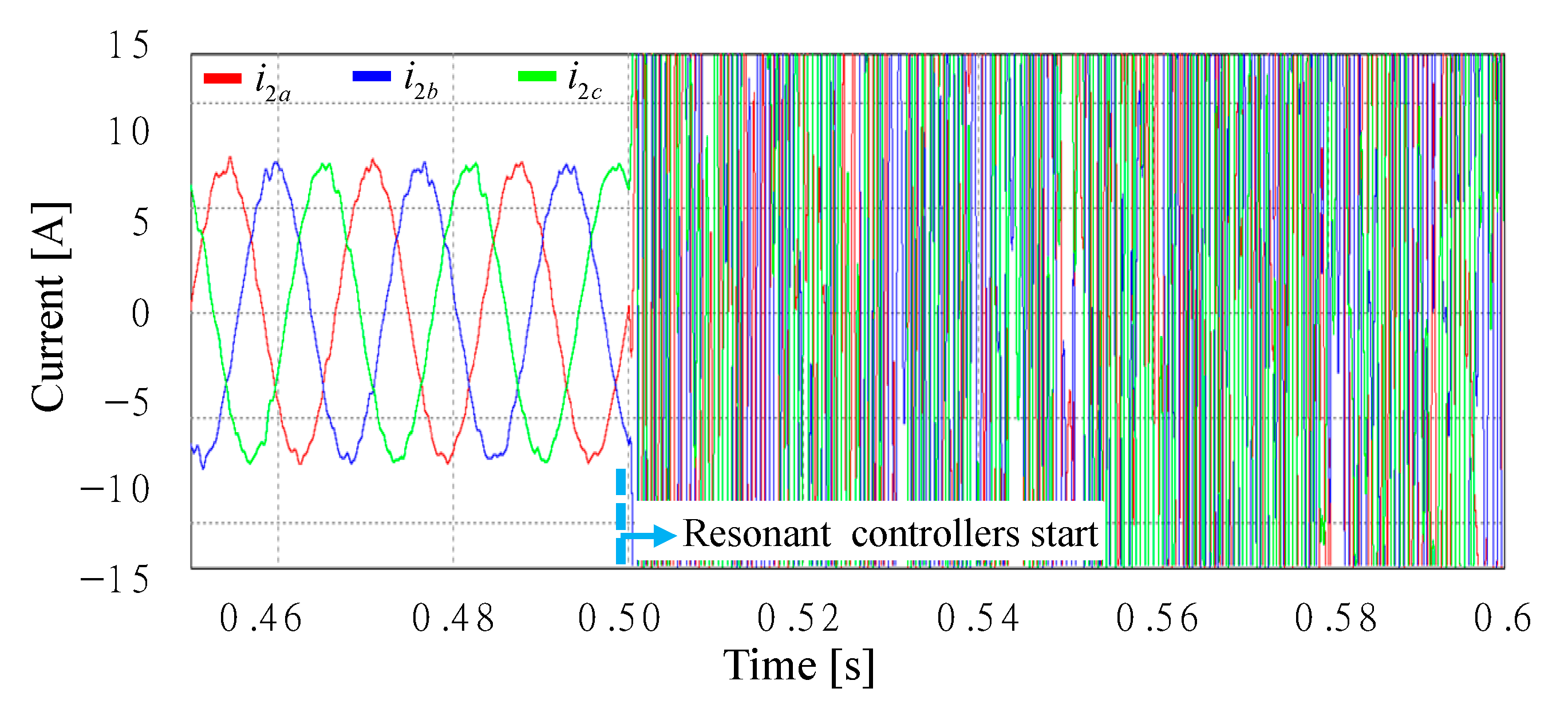
- By the movement of closed-loop poles and disturbance rejection responses, the stability margin of each controller is well investigated. It is clearly addressed that the stability is weakened under the grid impedance variation by the addition of harmonic resonant controllers. The theoretical results are validated by simulation and experiments.
- (3)
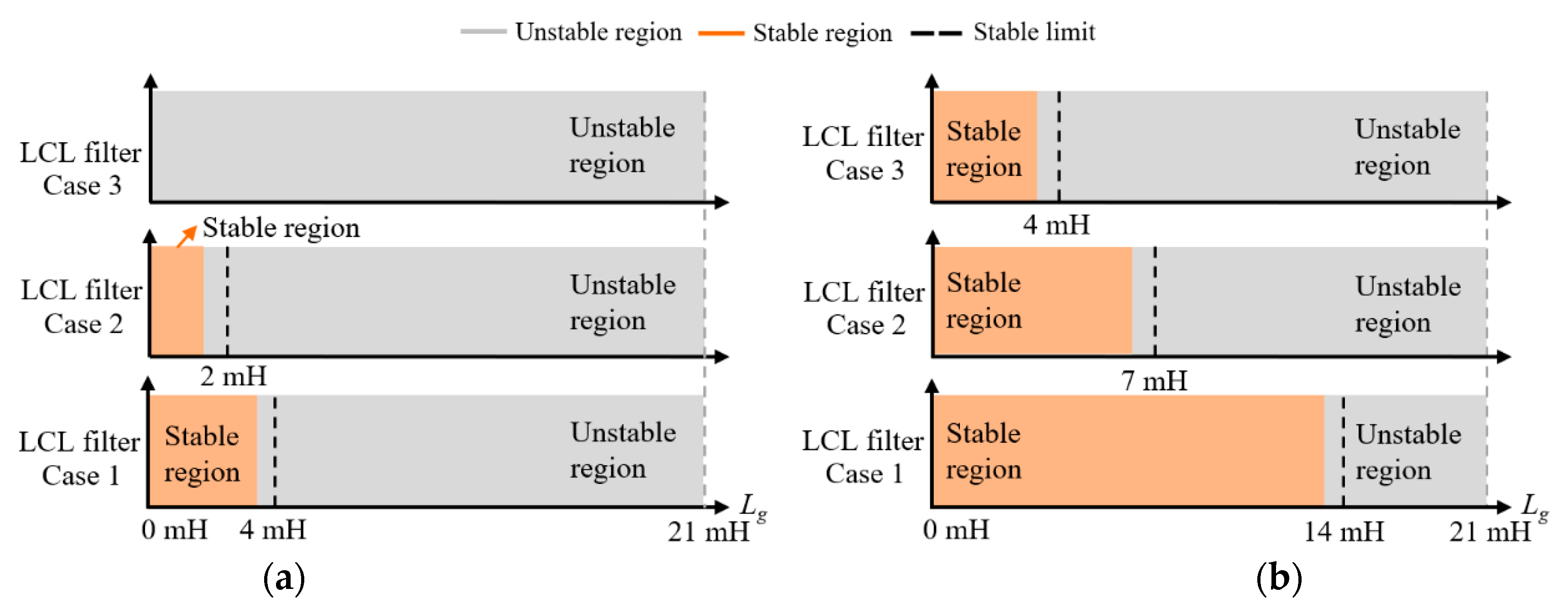
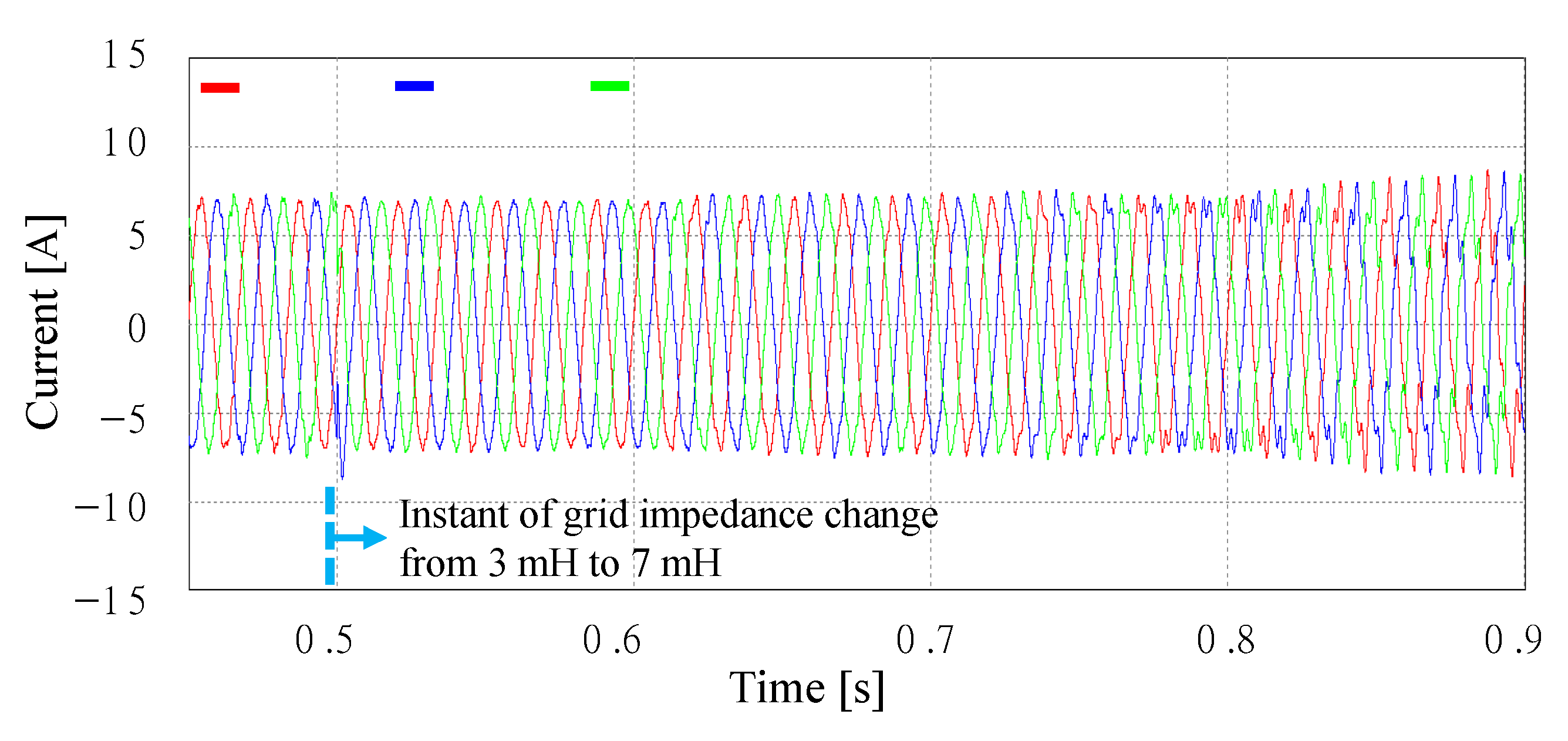
- The full-state feedback current control method with augmented harmonic resonant compensators has well proved its robustness for a wide range of grid impedance variations (up to 14 times of grid-side inductors in the high region) by theoretical analysis and evaluation results.
- (4)
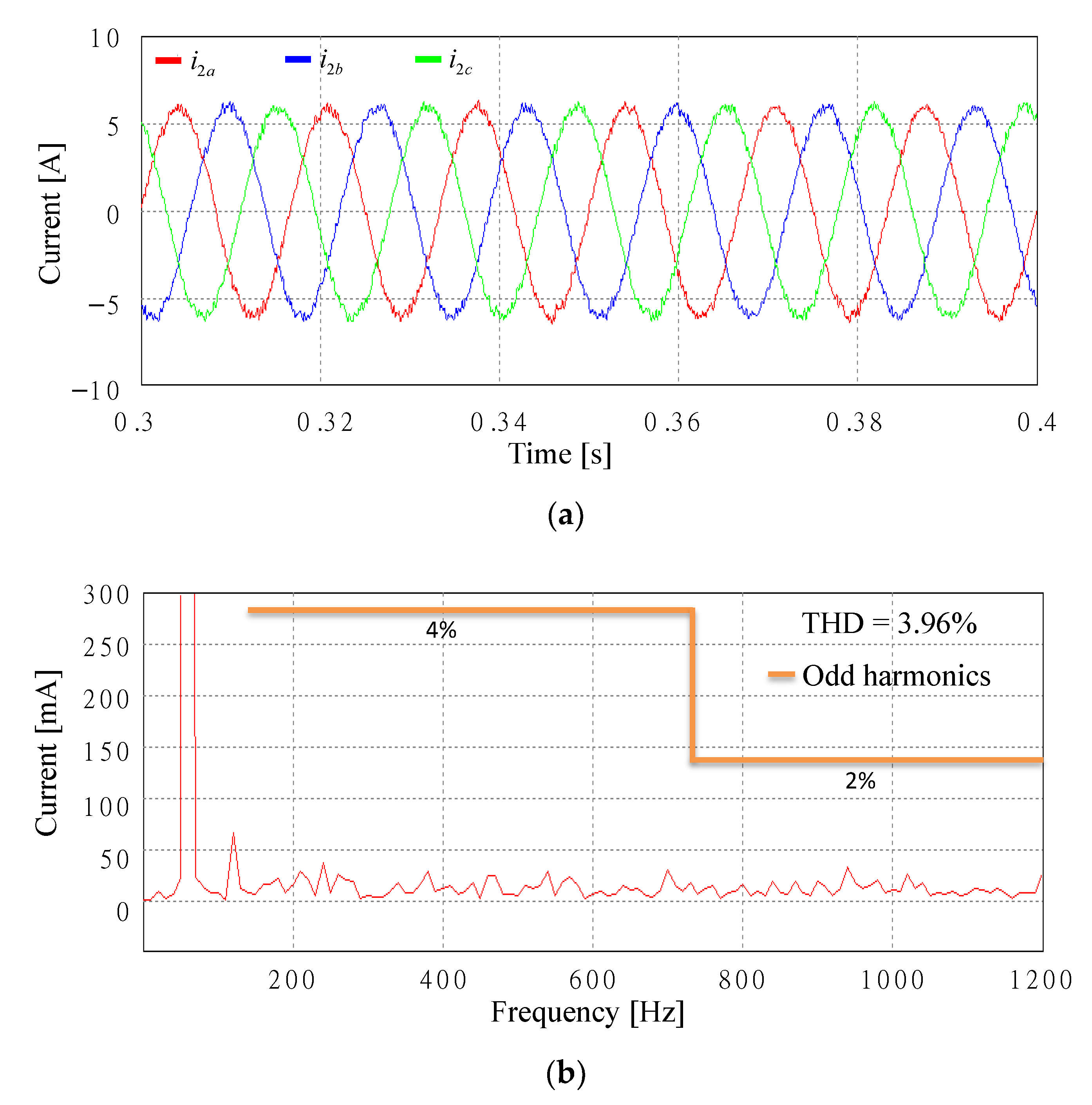
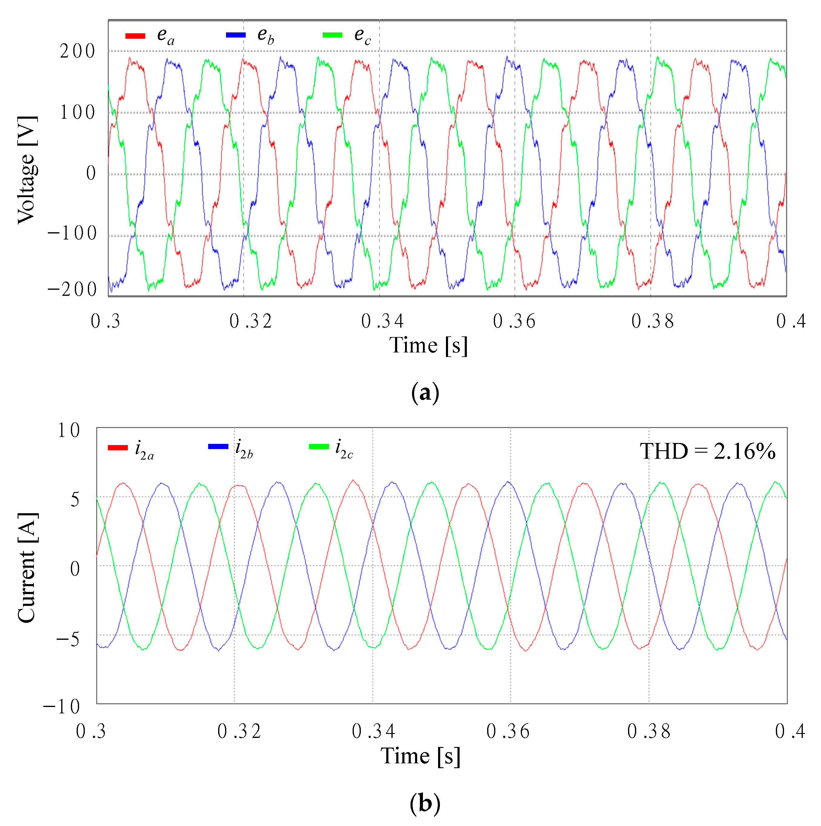
- In order to validate the presented theoretical analyses, comprehensive simulation and experimental results based on 2 kVA grid-connected inverter are presented under the grid environment including both uncertain grid impedance and distorted harmonics.
2. System Description and Current Controller
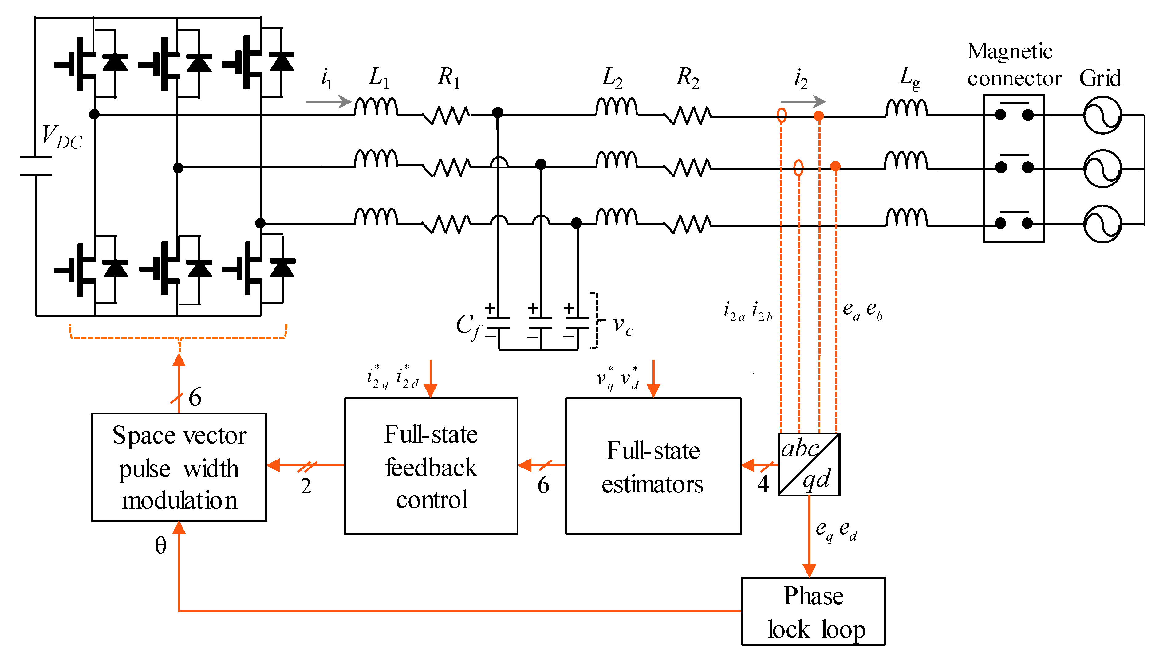
2.1. System Model of Grid-Connected Inverter
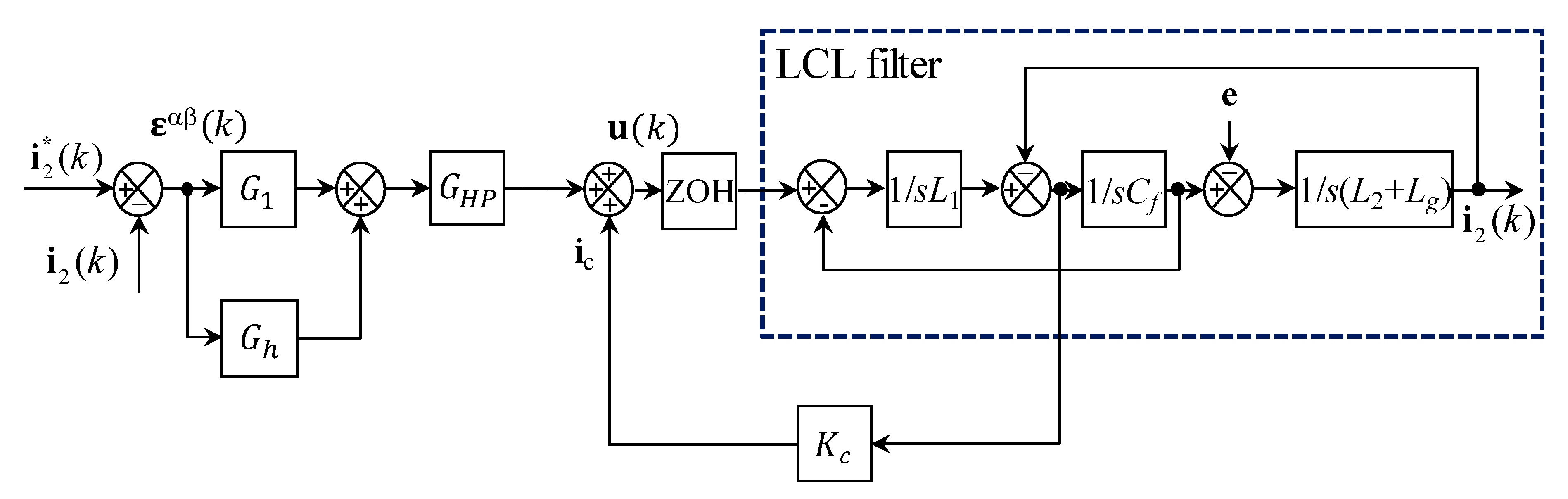
2.2. Direct Current Control Based on Capacitor Current Damping
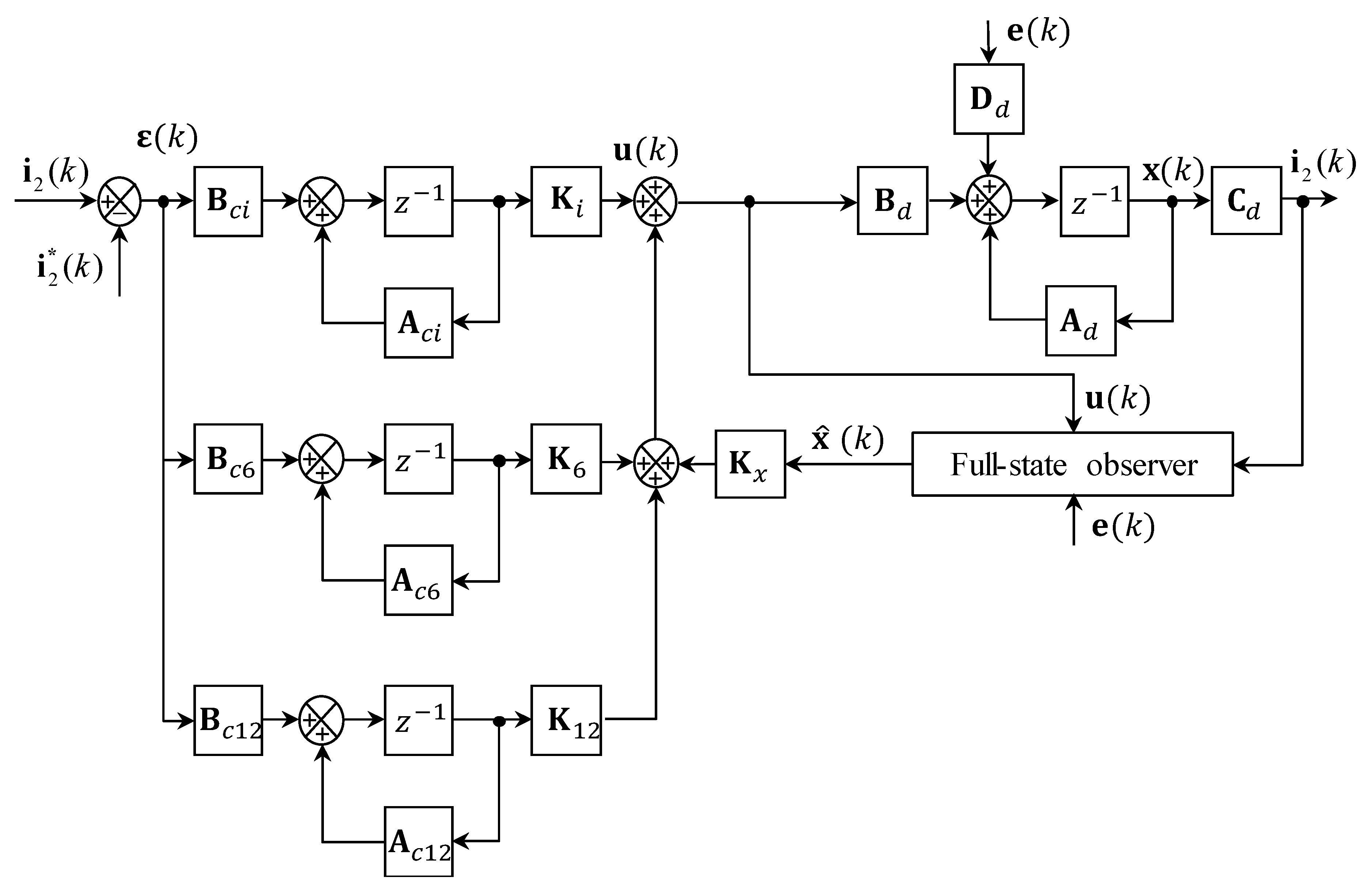
2.3. Integral-Resonant State Feedback Control
3. Stability Analysis under Weak Grid
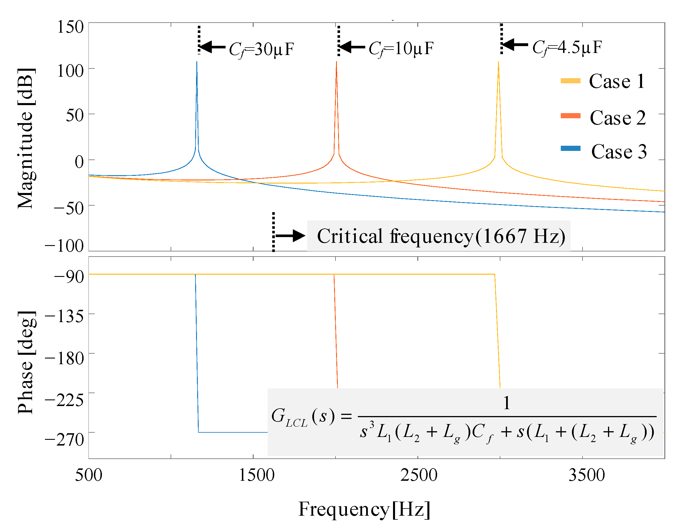
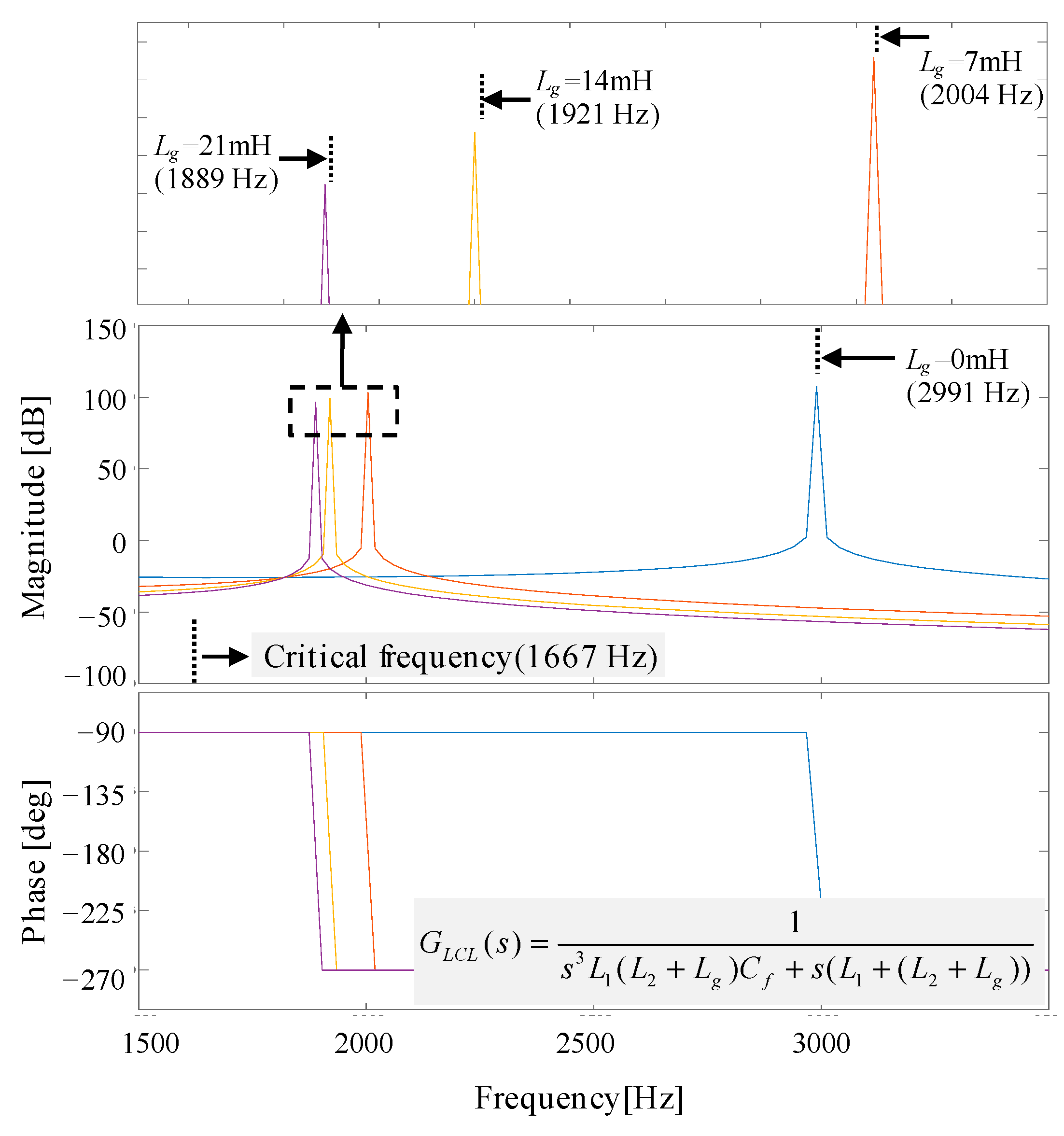
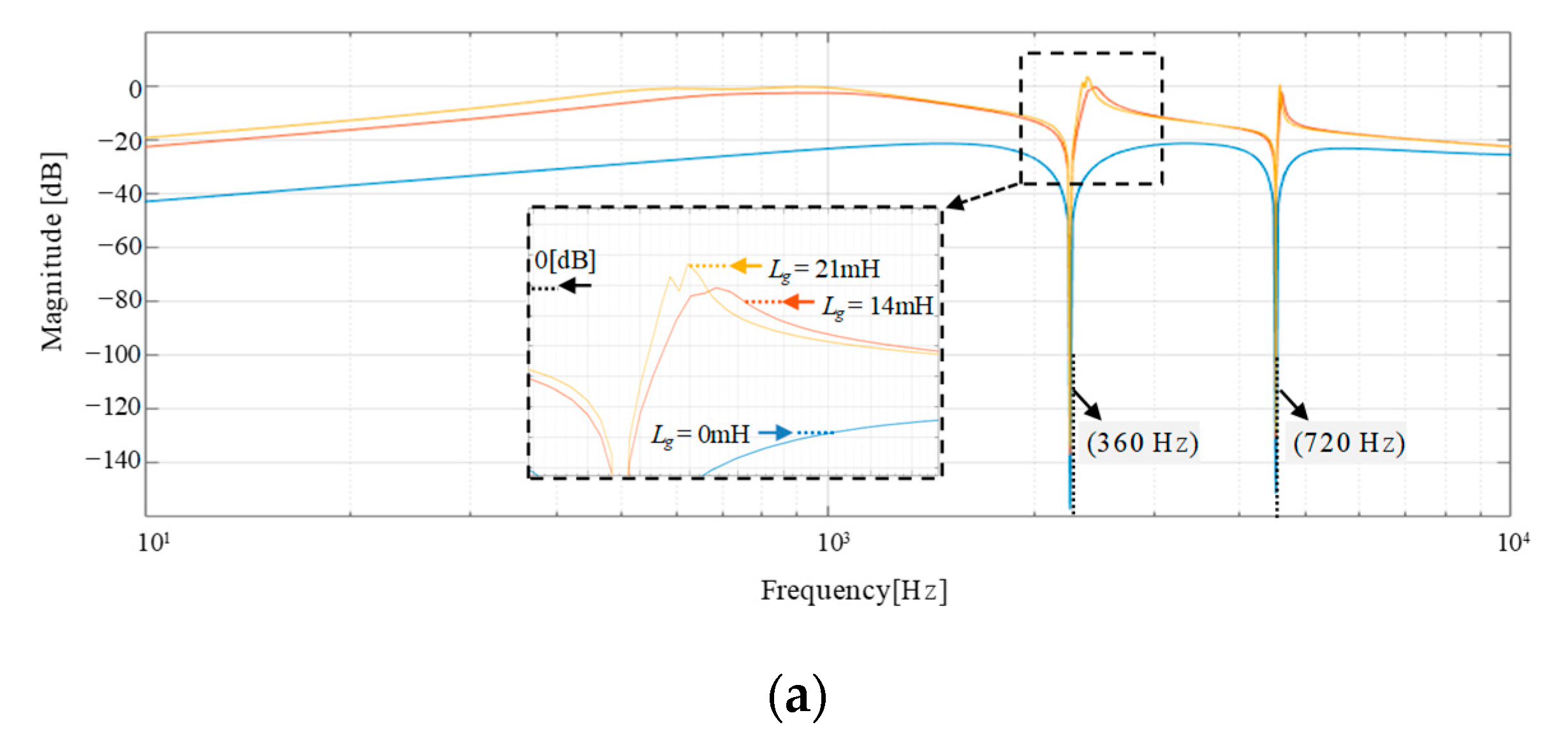
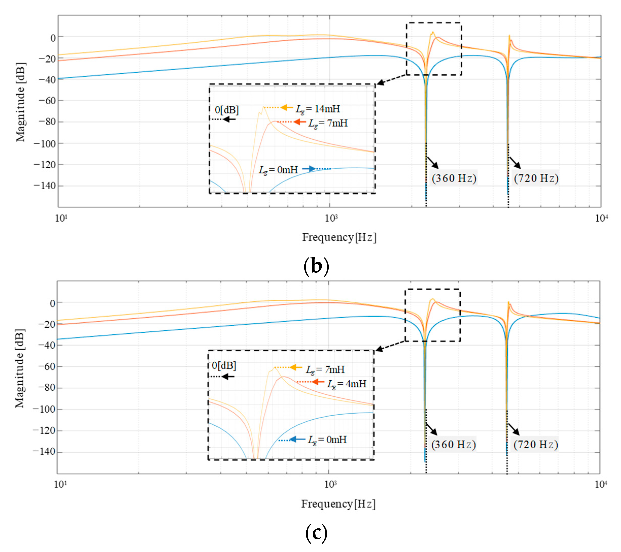
3.1. Frequency Response of LCL Filter under Grid Impedance Change
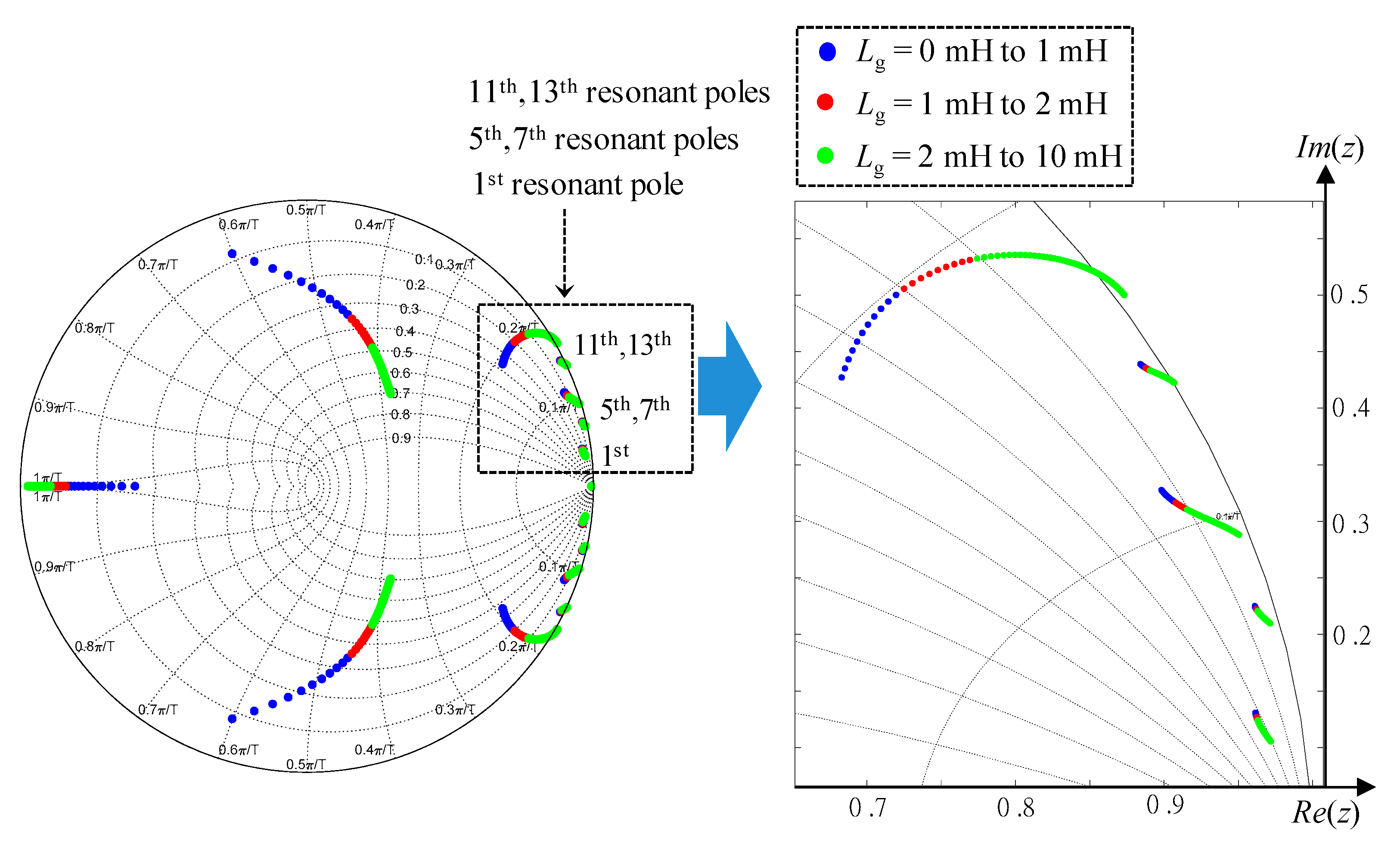
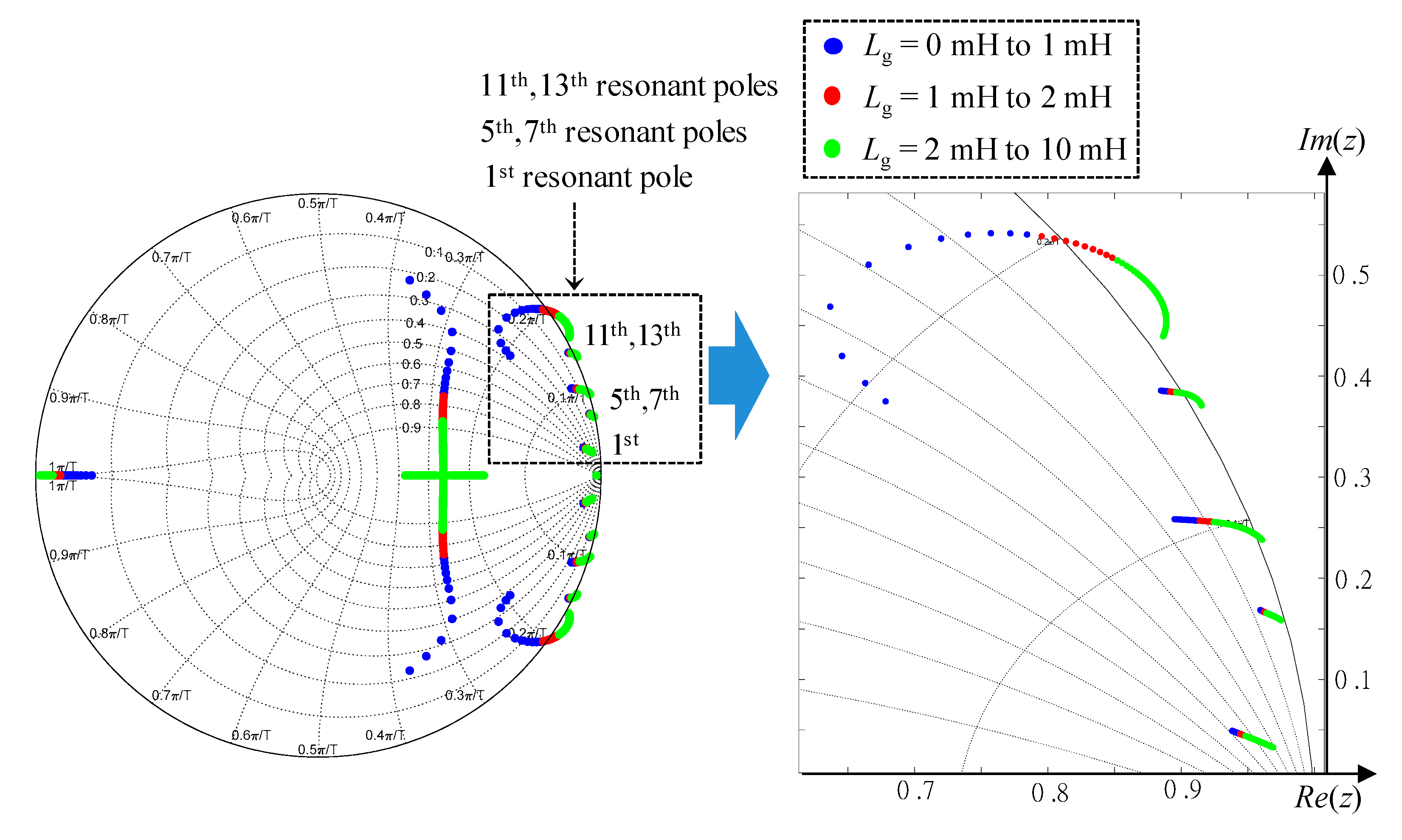
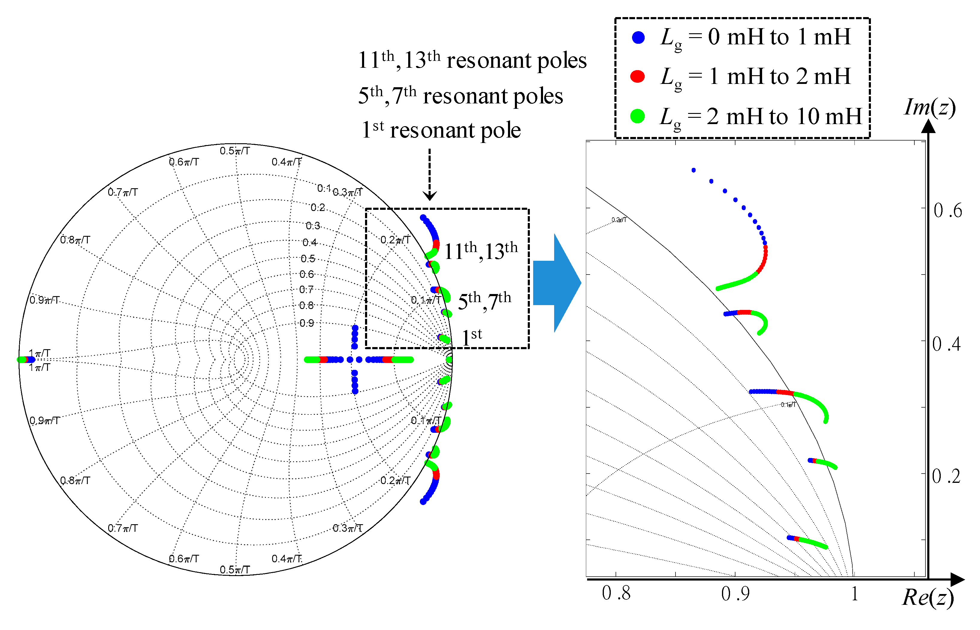
3.2. Closed-Loop Stability of Direct Grid Current Control with Active Damping under Grid Impedance Change
3.3. Closed-Loop Stability of Integral-Resonant State Feedback LQR Control under Grid Impedance Change
4. Performance Assessment under Distorted Weak Grid Condition
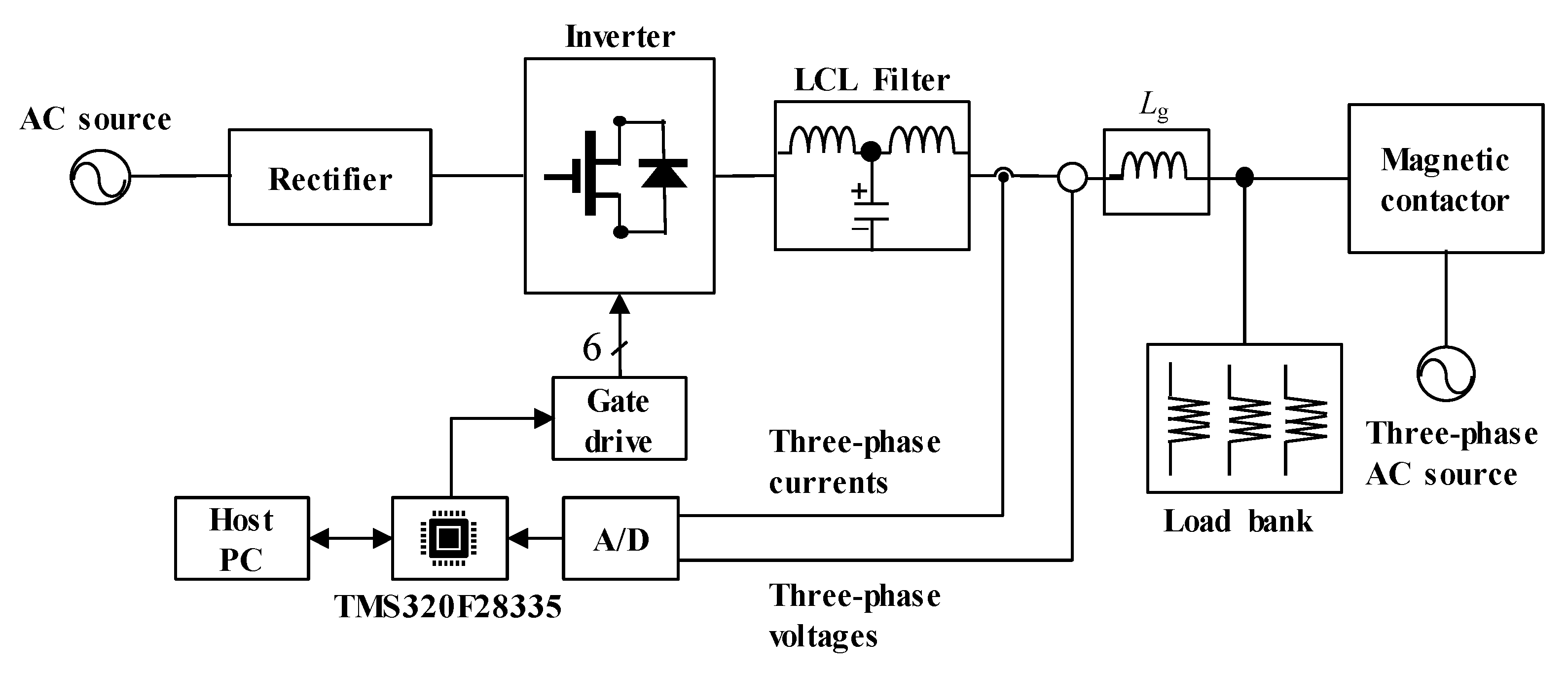
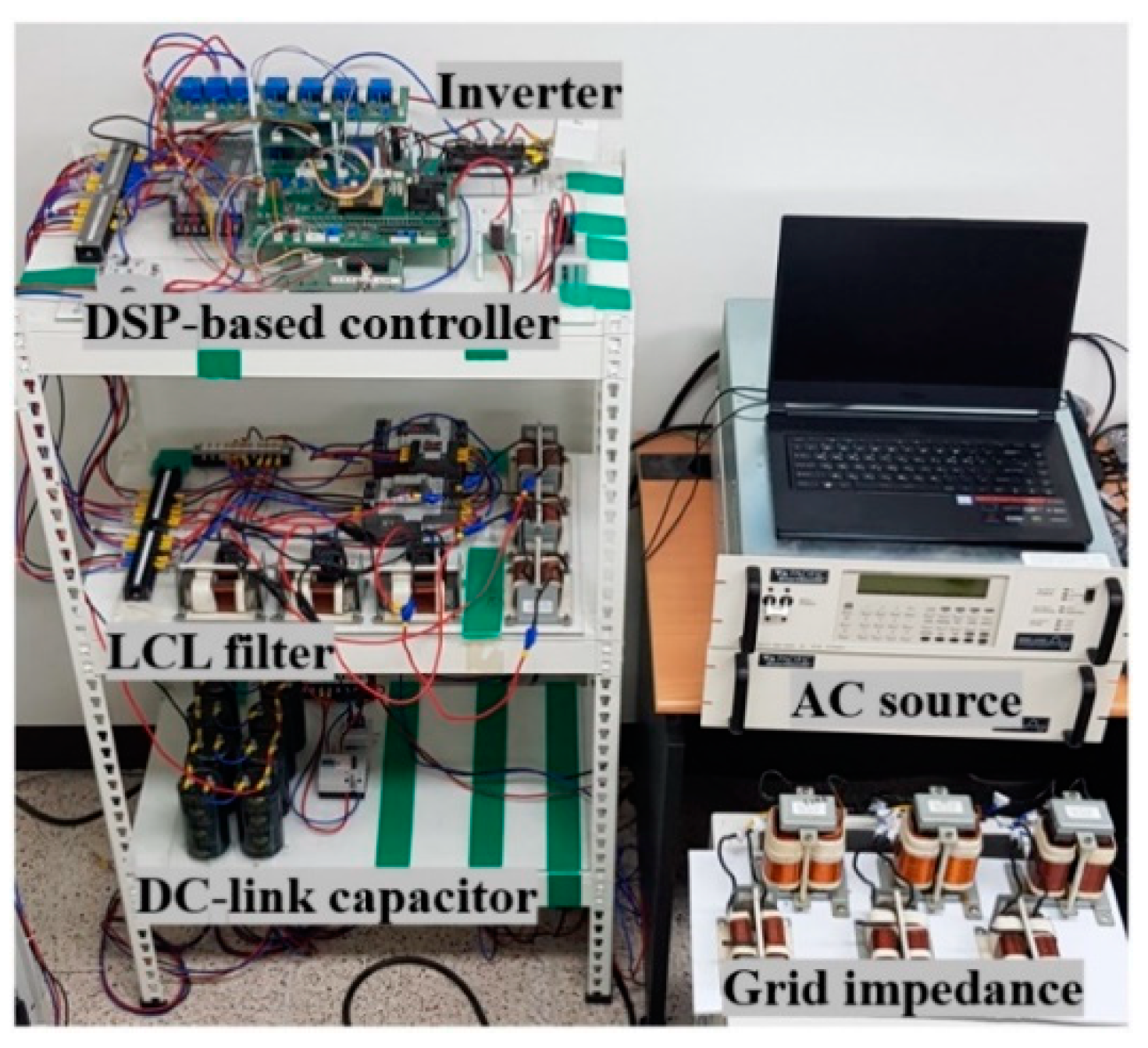
4.1. System Configuration
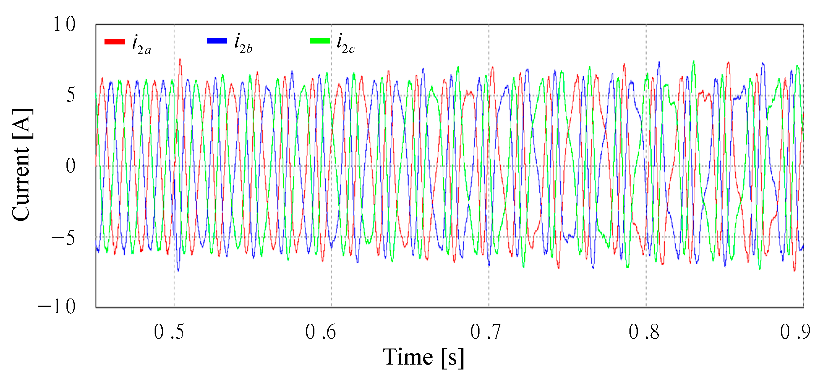
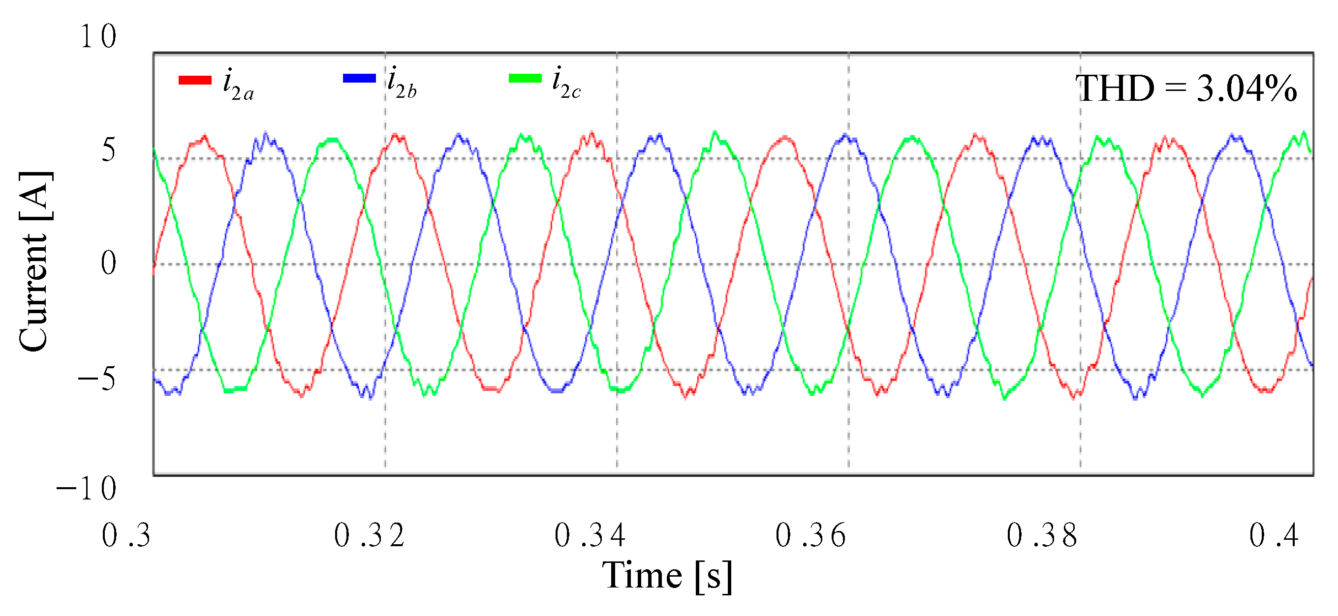
4.2. Simulation Results
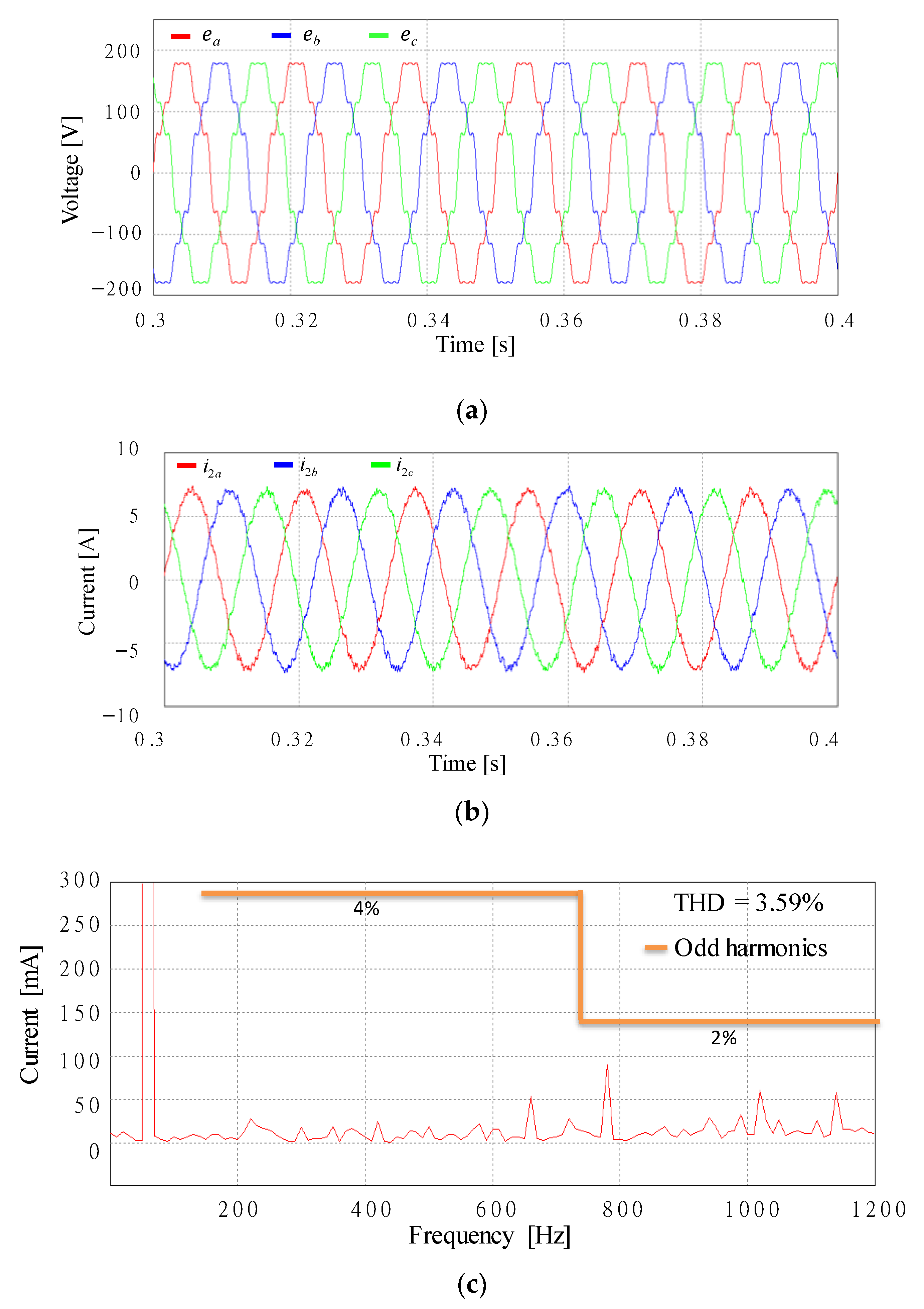
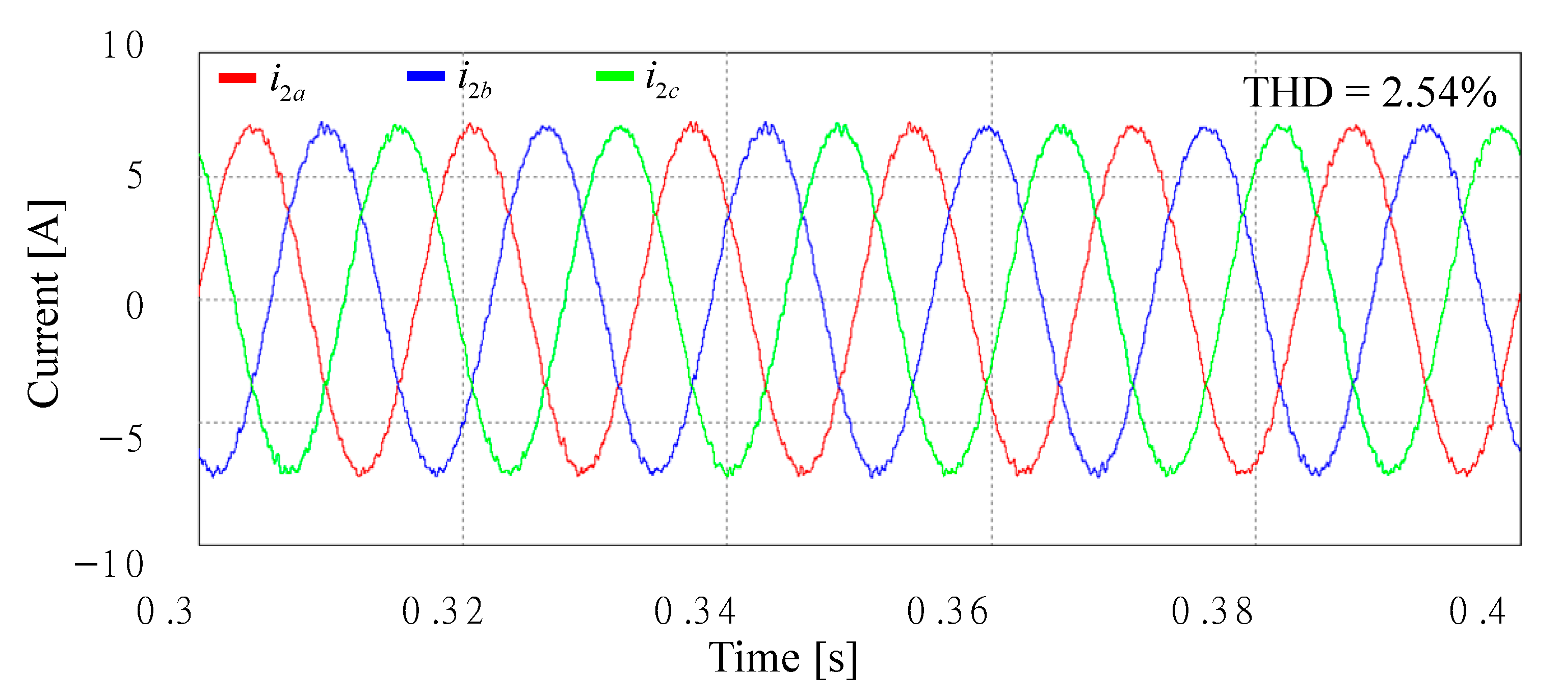
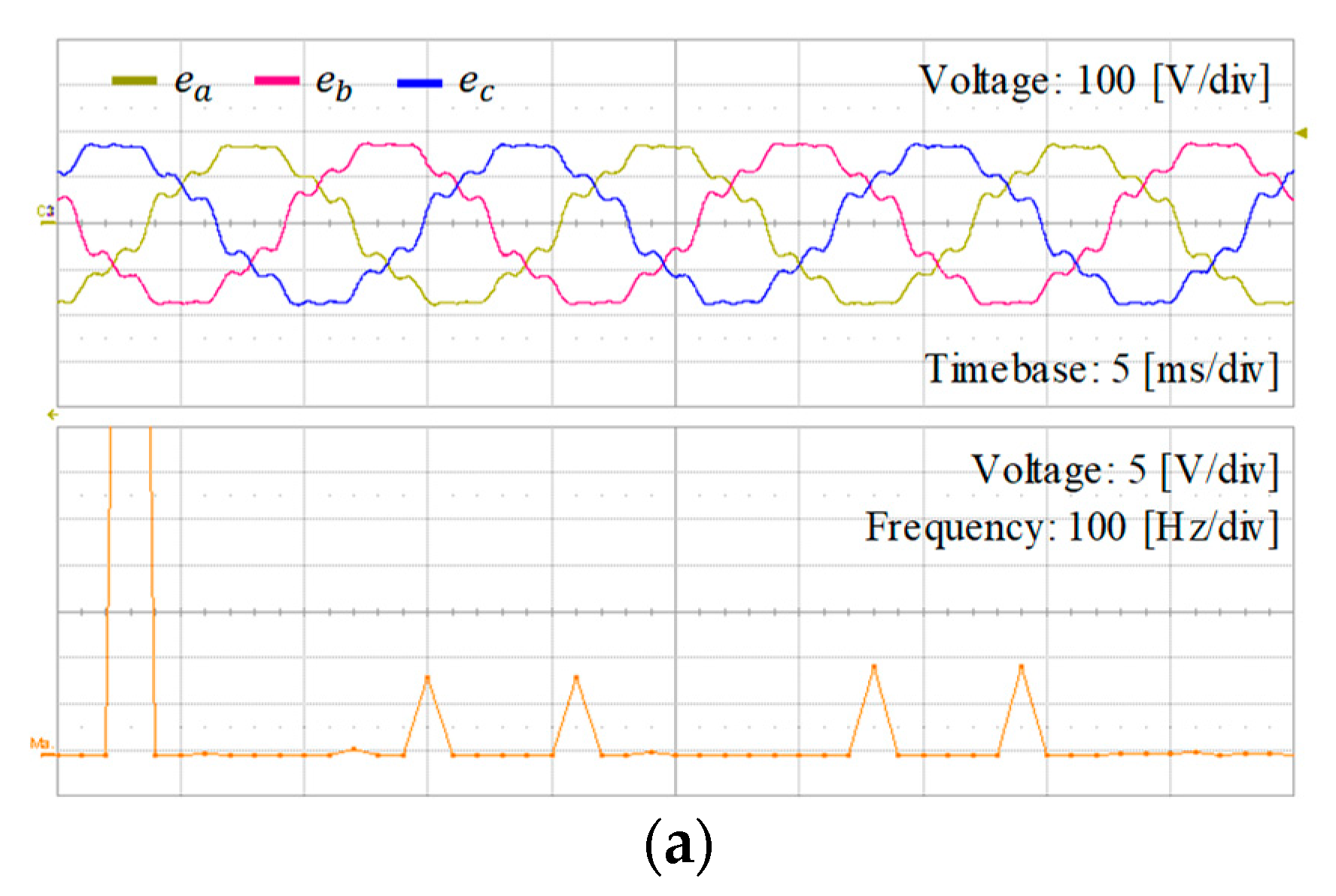
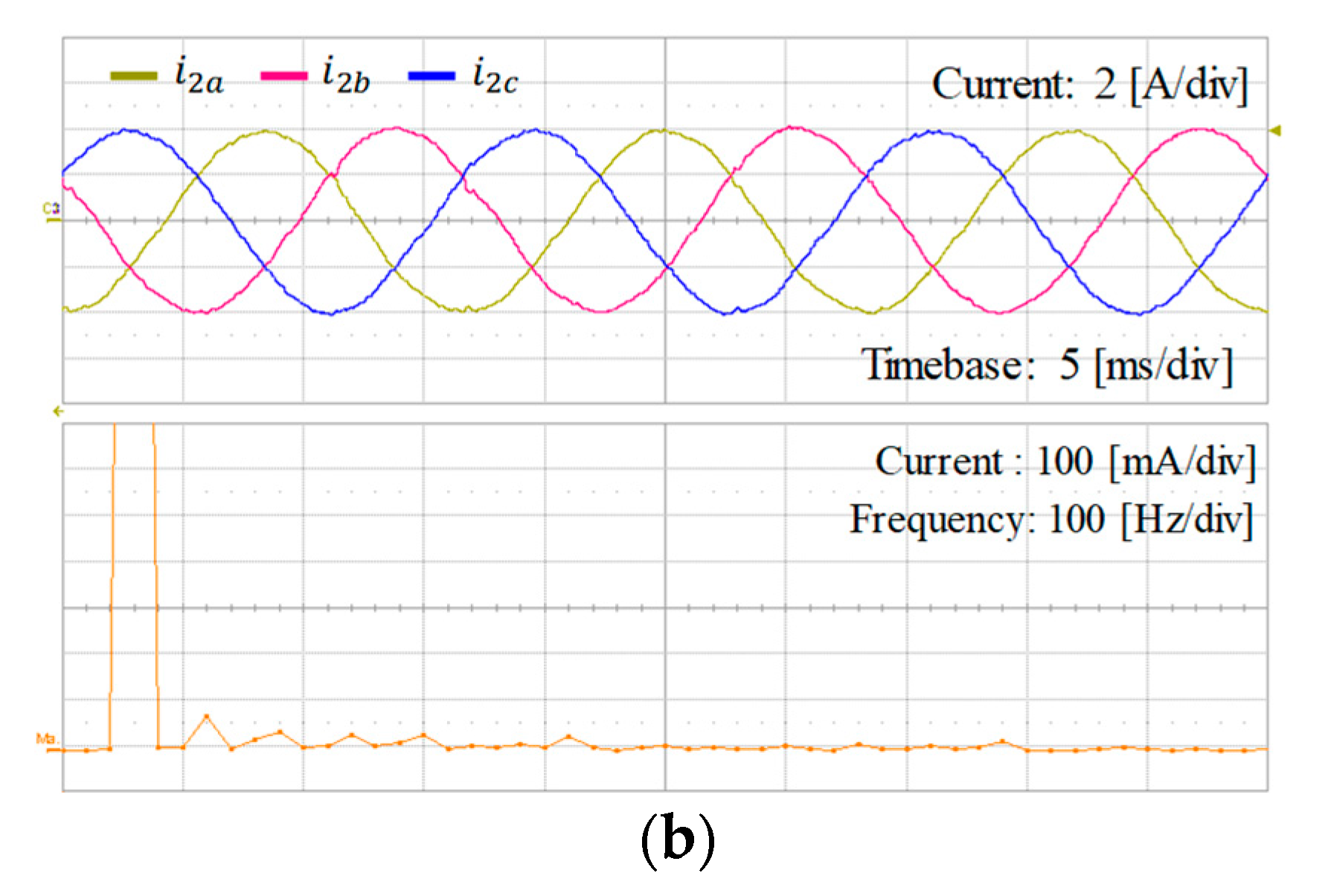
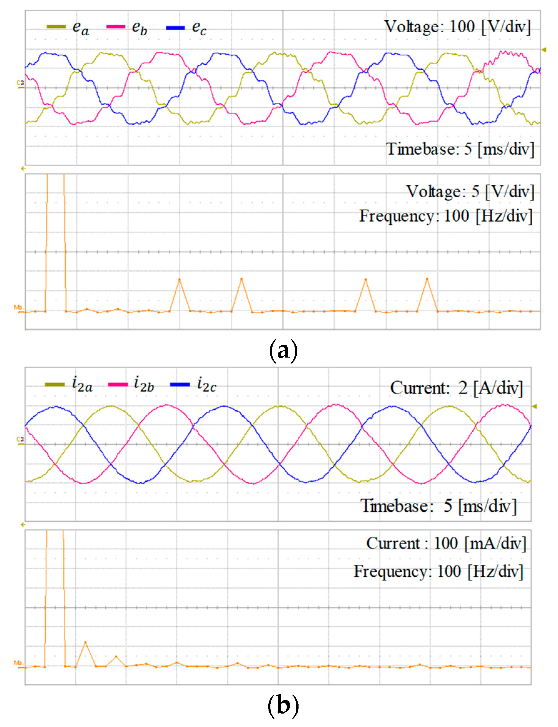
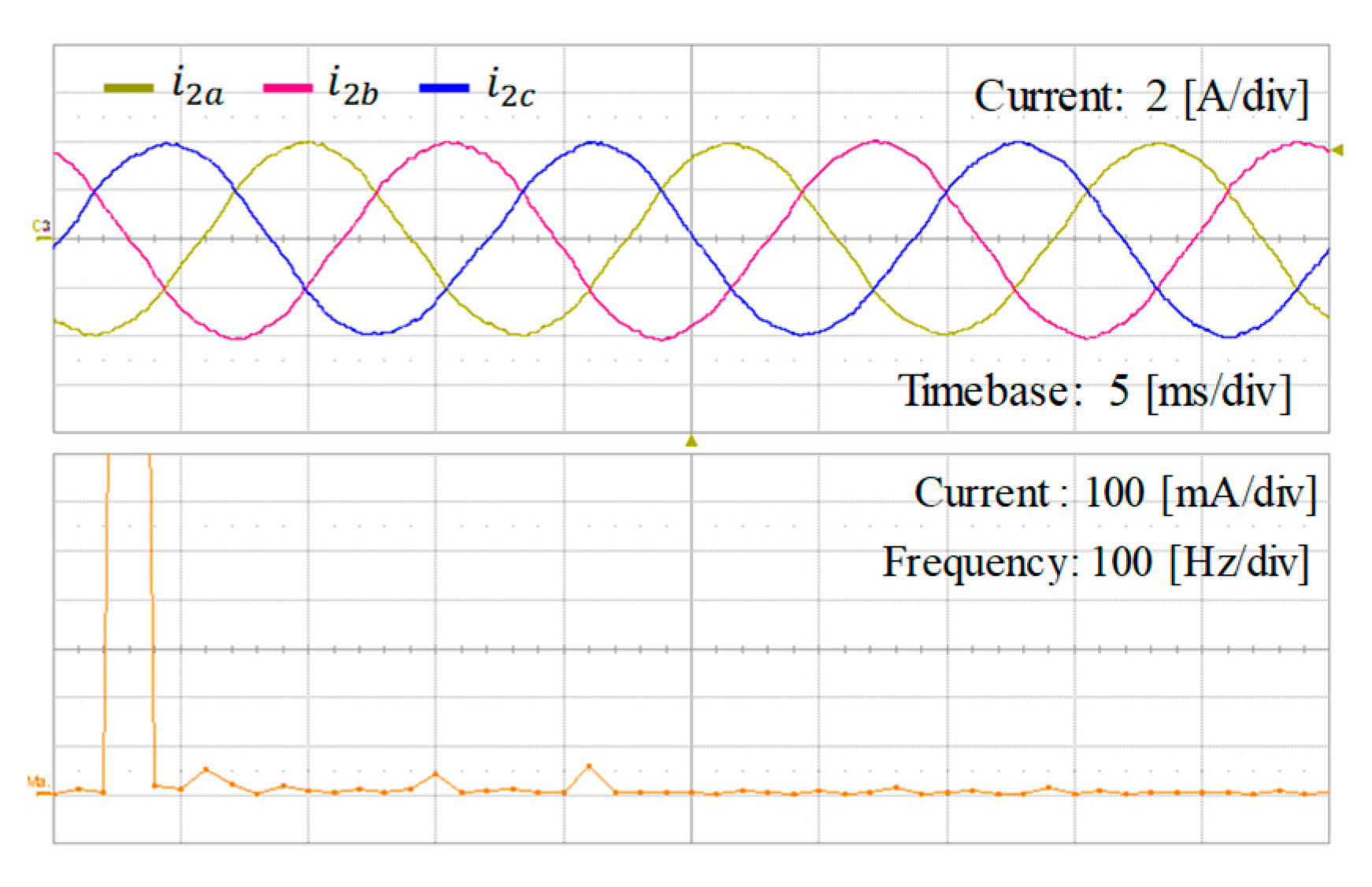
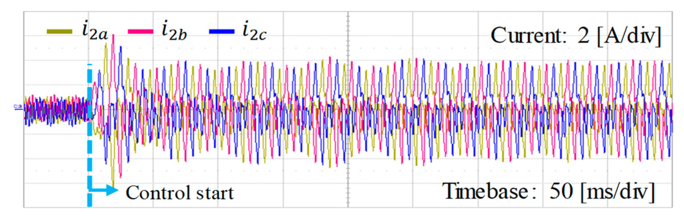
4.3. Experimental Results
5. Conclusions
Author Contributions
Funding
Institutional Review Board Statement
Informed Consent Statement
Data Availability Statement
Acknowledgments
Conflicts of Interest
References
- Blaabjerg, F.; Teodorescu, R.; Liserre, M.; Timbus, A.V. Overview of control and grid synchronization for distributed power generation systems. IEEE Trans. Ind. Electron. 2006, 53, 1398–1409. [Google Scholar] [CrossRef] [Green Version]
- Kroposki, B.; Johnson, B.; Zhang, Y.; Gevorgian, V.; Denholm, P.; Hodge, B.M.; Hannegan, B. Achieving a 100% renewable grid: Operating electric power systems with extremely high levels of variable renewable energy. IEEE Power Energy Mag. 2017, 15, 61–73. [Google Scholar] [CrossRef]
- Liserre, M.; Blaabjerg, F.; Hansen, S. Design and control of an LCL-filter-based three-phase active rectifier. IEEE Trans. Ind. Appl. 2005, 41, 1281–1291. [Google Scholar] [CrossRef]
- Pan, D.; Ruan, X.; Wang, X. Direct realization of digital differentiators in discrete domain for active damping of LCL-type grid-connected inverter. IEEE Trans. Power Electron. 2018, 33, 8461–8473. [Google Scholar] [CrossRef] [Green Version]
- Han, Y.; Yang, M.; Li, H.; Yang, P.; Xu, L.; Coelho, E.A.A.; Guerrero, J.M. Modeling and stability analysis of LCL-Type grid-connected inverters a comprehensive overview. IEEE Access 2019, 7, 114975–115001. [Google Scholar] [CrossRef]
- Reznik, A.; Simoes, M.G.; Al-Durra, A.; Muyeen, S.M. LCL filter design and performance analysis for grid-interconnected systems. IEEE Trans. Ind. Appl. 2014, 50, 1225–1232. [Google Scholar] [CrossRef]
- Beres, R.N.; Wang, X.; Liserre, M.; Blaabjerg, F. A review of passive power filters for three-phase grid-connected voltage-source converters. IEEE J. Emerg. Sel. Top. Power Electron. 2016, 4, 54–69. [Google Scholar] [CrossRef] [Green Version]
- Liserre, M.; Teodorescu, R.; Blaabjerg, F. Stability of photovoltaic and wind turbine grid-connected inverters for a large set of grid impedance values. IEEE Trans. Power Election. 2006, 21, 263–272. [Google Scholar] [CrossRef]
- Castilla, M.; Miret, J.; Matas, J.; Garcia de Vicuna, L.; Guerrero, J.M. Control design guidelines for single-phase grid-connected photovoltaic inverters with damped resonant harmonic compensators. IEEE Trans. Ind. Electron. 2009, 56, 4492–4501. [Google Scholar] [CrossRef]
- Yang, D.; Ruan, X.; Wu, H. Impedance shaping of the grid-connected inverter with LCL filter to improve its adaptability to the weak grid condition. IEEE Trans. Power Electron. 2014, 29, 5795–5805. [Google Scholar] [CrossRef]
- Wu, W.; Liu, Y.; He, Y.; Chung, H.S.H.; Liserre, M.; Blaabjerg, F. Damping methods for resonances caused by LCL-filter-based current-controlled grid-tied power inverters: An overview. IEEE Trans. Ind. Electron. 2017, 64, 7402–7413. [Google Scholar] [CrossRef] [Green Version]
- Yao, W.; Yang, Y.; Zhang, X.; Blaabjerg, F.; Loh, P.C. Design and analysis of robust active damping for LCL filters using digital notch filters. IEEE Trans. Power Electron. 2017, 32, 2360–2375. [Google Scholar] [CrossRef] [Green Version]
- Jia, Y.; Zhao, J.; Xiaowuei, F. Direct grid current control of LCL-filtered grid-connected inverter mitigating grid voltage disturbance. IEEE Trans. Power Electron. 2014, 29, 1532–1541. [Google Scholar]
- Li, X.; Fang, J.; Tang, Y.; Wu, X.; Geng, Y. Capacitor-voltage feedforward with full delay compensation to improve weak grids adaptability of LCL-filtered grid-connected converters for distributed generation systems. IEEE Trans. Power Electron. 2018, 33, 749–764. [Google Scholar] [CrossRef]
- Tran, T.V.; Yoon, S.J.; Kim, K.H. An LQR-based controller design for an LCL-filtered grid-connected inverter in discrete-time state-space under distorted grid environment. Energies 2018, 11, 2062. [Google Scholar] [CrossRef] [Green Version]
- Bimarta, R.; Tran, T.V.; Kim, K.H. Frequency-adaptive current controller design based on LQR state feedback control for a grid-connected inverter under distorted grid. Energies 2018, 11, 2674. [Google Scholar] [CrossRef] [Green Version]
- Busada, C.A.; Jorge, S.G.; Solsona, J.A. Full-state feedback equivalent controller for active damping in LCL-filtered grid-connected inverters using a reduced number of sensors. IEEE Trans. Ind. Electron. 2015, 62, 5993–6002. [Google Scholar] [CrossRef]
- Xue, M.; Zhang, Y.; Kang, Y.; Yi, Y.; Li, S.; Liu, F. Full feedforward of grid voltage for discrete state feedback controlled grid-connected inverter with LCL filter. IEEE Trans. Power Electron. 2012, 27, 4234–4247. [Google Scholar] [CrossRef]
- He, J.; Li, Y.W. Generalized closed-loop control schemes with embedded virtual impedances for voltage source converters with LC or LCL filters. IEEE Trans. Power Electron. 2012, 27, 1850–1861. [Google Scholar] [CrossRef]
- Ruan, X.; Wang, X.; Pan, D.; Yang, D.; Li, W.; Bao, C. Control Techniques for LCL-Type Grid-Connected Inverters, 1st ed.; Science Press: Beijing, China, 2015. [Google Scholar]
- Guzman, R.; Garcia de Vicuna, L.; Castilla, M.; Miret, M.; de la Hoz, J. Variable structure control for three-phase LCL-filtered inverters using a reduced converter model. IEEE Trans. Ind. Electron. 2018, 65, 5–15. [Google Scholar] [CrossRef]
- Rohten, J.A.; Espinoza, J.R.; Muñoz, J.A.; Pérez, M.A.; Melin, P.E.; Silva, J.J.; Espinosa, E.E.; Rivera, M.E. Model predictive control for power converters in a distorted three-phase power supply. IEEE Trans. Ind. Electron. 2016, 63, 5838–5848. [Google Scholar] [CrossRef]
- Trinh, Q.N.; Wang, P.; Tang, Y.; Choo, F.H. Mitigation of DC and harmonic currents generated by voltage measurement errors and grid voltage distortions in transformerless grid-connected inverters. IEEE Trans. Energy Convers. 2018, 33, 801–813. [Google Scholar] [CrossRef]
- Elkayam, M.; Kuperman, A. Optimized design of multiresonant AC current regulators for single-phase grid-connected photovoltaic inverters. IEEE J. Photovolt. 2019, 9, 1815–1818. [Google Scholar] [CrossRef]
- Parker, S.G.; McGrath, B.P.; Holmes, D.G. Regions of active damping control for LCL filters. IEEE Trans. Ind. Appl. 2014, 50, 424–432. [Google Scholar] [CrossRef]
- Xu, J.; Xie, S.; Tang, T. Evaluations of current control in weak grid case for grid-connected LCL-filtered inverter. IET Power Electron. 2012, 6, 227–234. [Google Scholar] [CrossRef]
- Li, M.; Zhang, X.; Zhao, W. A novel stability improvement strategy for a multi-inverter system in a weak grid utilizing dual-mode control. Energies 2018, 11, 2144. [Google Scholar] [CrossRef] [Green Version]
- Wang, J.; Yao, J.; Hu, H.; Xing, Y.; He, X.; Sun, K. Impedance-based stability analysis of single-phase inverter connected to weak grid with voltage feed-forward control. In Proceedings of the IEEE Applied Power Electronics Conference and Exposition (APEC), Long Beach, CA, USA, 20–24 March 2016; pp. 2182–2186. [Google Scholar]
- Pérez-Estévez, D.; Doval-Gandoy, J.; Yepes, A.G.; López, Ó.; Baneira, F. Generalized multifrequency current controller for grid-connected converters with LCL filter. IEEE Trans. Ind. Appl. 2018, 54, 4537–4553. [Google Scholar] [CrossRef]
- Kalmbach, O.; Dirscherl, C.; Hackl, C.M. Discrete-time DC-link voltage and current control of a grid-connected inverter with LCL-filter and very small DC-link capacitance. Energies 2020, 13, 5613. [Google Scholar] [CrossRef]
- Dirscherl, C.; Fessler, J.; Hackl, C.M.; Ipach, H. State-feedback controller and observer design for grid-connected voltage source power converters with LCL-filter. In Proceedings of the 2015 IEEE Multi-Conference on Systems and Control (CCA), Sydney, Australia, 21–23 September 2015; pp. 215–222. [Google Scholar]
- Yoon, S.J.; Lai, N.B.; Kim, K.H. A systematic controller design for a grid-connected inverter with LCL filter using a discrete-time integral state feedback control and state observer. Energies 2018, 11, 1–20. [Google Scholar]
- Hoffmann, N.; Fuchs, F.W. Minimal invasive equivalent grid impedance estimation in inductive–resistive power networks using extended Kalman filter. IEEE Trans. Power Electron. 2014, 29, 631–641. [Google Scholar] [CrossRef]
- Tarraso, A.; Lai, N.B.; Baltas, G.N.; Rodriguez, P. Power quality services provided by virtually synchronous FACTS. Energies 2019, 12, 3292. [Google Scholar] [CrossRef] [Green Version]
- Texas Instrument. TMS320F28335 Digital Signal Controller (DSC)—Data Manual; Texas Instrument: Dallas, TX, USA, 2008. [Google Scholar]
- IEEE Standards Board. IEEE Standard for Interconnecting Distributed Resources with Electric Power Systems; IEEE Standard: Piscataway, NJ, USA, 2003; pp. 1547–2003. [Google Scholar]


| Cases | LCL Filter Parameters | fR |
|---|---|---|
| Case 1 | L1 = 1.7 mH, L2 = 1.0 mH, Cf = 4.5 µF | 2991 Hz |
| Case 2 | L1 = 1.7 mH, L2 = 1.0 mH, Cf = 10 µF | 2006 Hz |
| Case 3 | L1 = 1.7 mH, L2 = 1.0 mH, Cf = 30 µF | 1158 Hz |
| Parameters | Symbol | Value | Units |
|---|---|---|---|
| DC-link voltage | VDC | 400 | V |
| Filter resistance | R1, R2 | 0.5 | Ω |
| Nominal filter capacitance | Cf | 4.5 | μF |
| 10.0 | μF | ||
| 30.0 | μF | ||
| Filter capacitor resistance | Rcf | 16 | mΩ |
| Nominal inverter-side filter inductance | L1 | 1.7 | mH |
| Nominal grid-side filter inductance | L2 | 1.0 | mH |
| Grid voltage (line-to-line rms) | e | 220 | V |
| Nominal grid frequency | fg | 60 | Hz |
| LCL Filter | Grid Inductance | THD in Simulation | Harmonic Magnitude in Experiment Integral-Resonant State Feedback Control | ||||
|---|---|---|---|---|---|---|---|
| Integral-Resonant State Feedback Control | Direct Grid Current Control | 2 h | 5 h | 7 h | 11 h | ||
| Case 1 | Lg = 0 mH | 3.96% | 3.59% | <0.8% | <0.4% | <0.2% | <0.1% |
| Lg = 7 mH | 2.16% | - | <1.5% | <0.2% | <0.1% | <0.1% | |
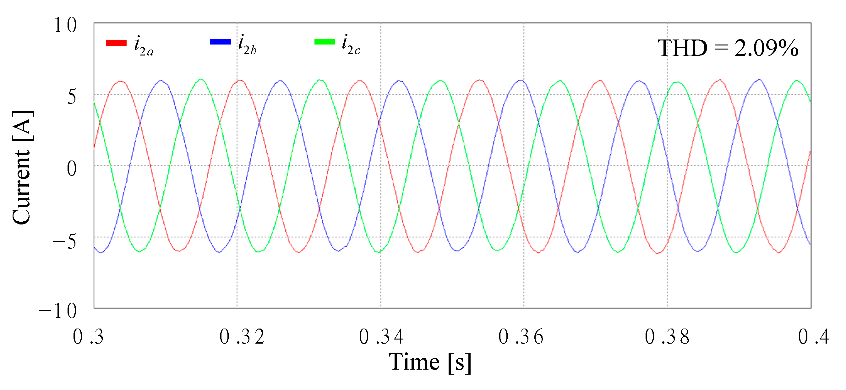
| Lg = 14 mH | 2.09% | - | <0.8% | <0.6% | <0.9% | <0.1% | |
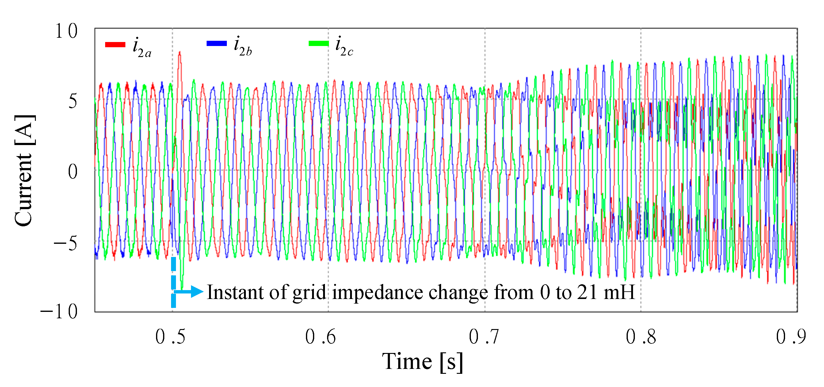
| Lg = 21 mH | - | - | - | - | - | - | |
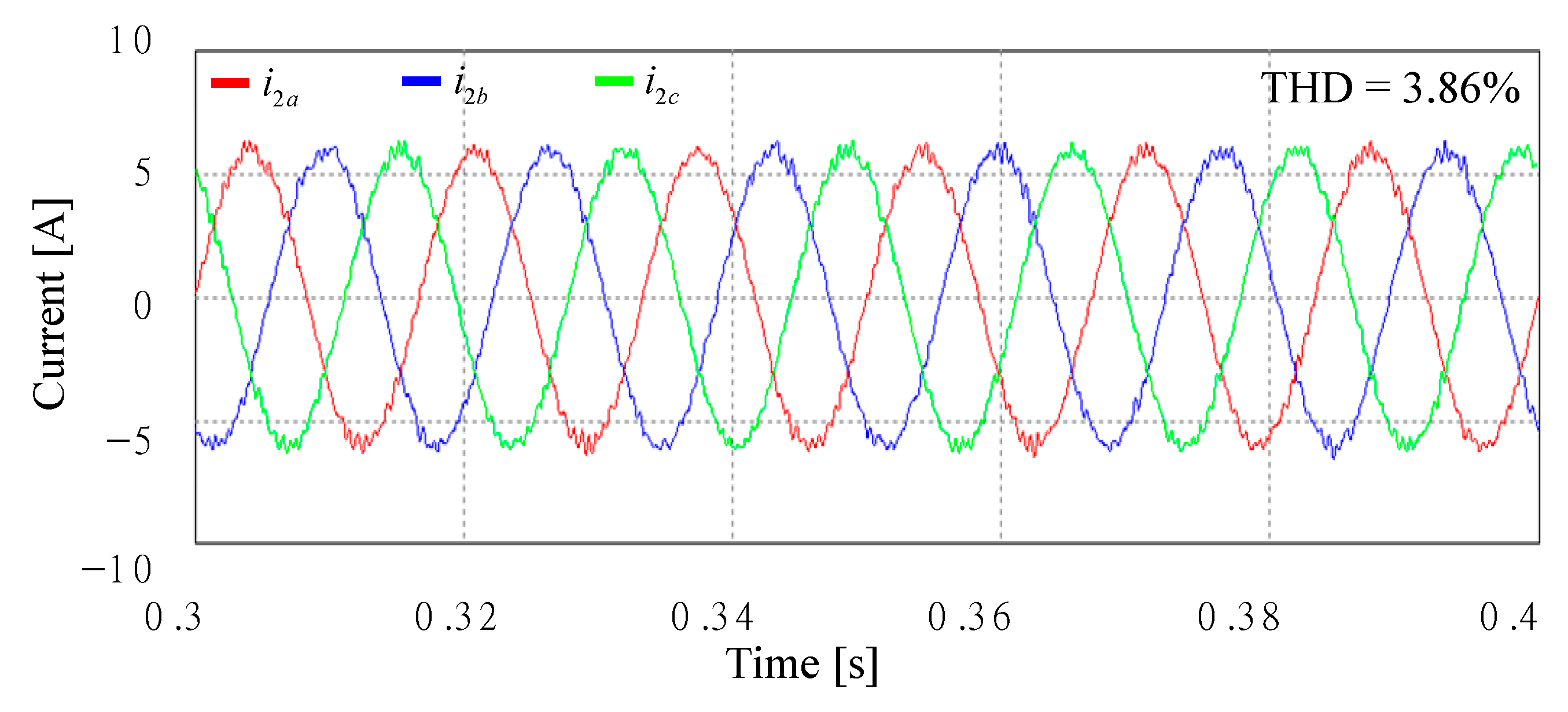
| Case 2 | Lg = 0 mH | 3.86% | 2.54% | <0.7% | <0.1% | <0.2% | <0.1% |
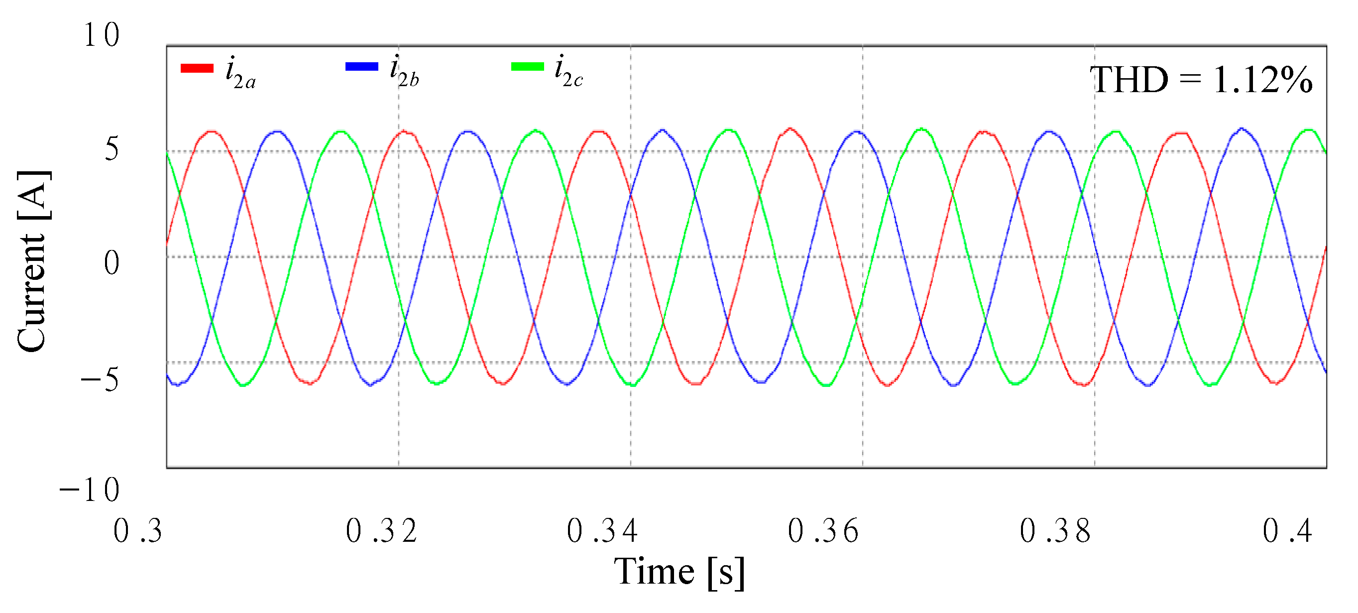
| Lg = 7 mH | 1.12% | - | <2.2% | <0.1% | <0.2% | <0.1% | |
| Lg = 14 mH | - | - | |||||
| Case 3 | Lg = 0 mH | 3.04% | - | <0.7% | <0.2% | <0.2% | <0.1% |
| Lg = 7 mH | - | - | |||||
Publisher’s Note: MDPI stays neutral with regard to jurisdictional claims in published maps and institutional affiliations. |
© 2020 by the authors. Licensee MDPI, Basel, Switzerland. This article is an open access article distributed under the terms and conditions of the Creative Commons Attribution (CC BY) license (http://creativecommons.org/licenses/by/4.0/).
Share and Cite
Yoon, S.-J.; Tran, T.V.; Kim, K.-H. Stability Assessment of Current Controller with Harmonic Compensator for LCL-Filtered Grid-Connected Inverter under Distorted Weak Grid. Appl. Sci. 2021, 11, 212. https://doi.org/10.3390/app11010212
Yoon S-J, Tran TV, Kim K-H. Stability Assessment of Current Controller with Harmonic Compensator for LCL-Filtered Grid-Connected Inverter under Distorted Weak Grid. Applied Sciences. 2021; 11(1):212. https://doi.org/10.3390/app11010212
Chicago/Turabian StyleYoon, Seung-Jin, Thuy Vi Tran, and Kyeong-Hwa Kim. 2021. "Stability Assessment of Current Controller with Harmonic Compensator for LCL-Filtered Grid-Connected Inverter under Distorted Weak Grid" Applied Sciences 11, no. 1: 212. https://doi.org/10.3390/app11010212