Article

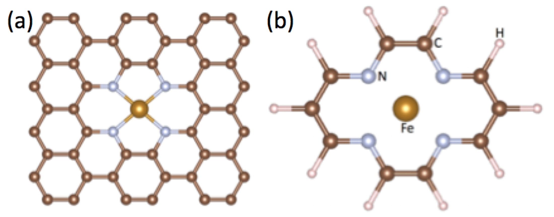
Many-Body Effects in FeN4 Center Embedded in Graphene

1
Department of Physics, Northeastern University, Boston, MA 02115, USA
2
Department of Mechanical Engineering, Carnegie Mellon University, Pittsburgh, PA 15213, USA
3
Department of Physics, School of Engineering Science, LUT University, FI-53851 Lappeenranta, Finland
*
Author to whom correspondence should be addressed.
LUT University is the main affiliation of Bernardo Barbiellini.
Appl. Sci. 2020, 10(7), 2542; https://doi.org/10.3390/app10072542
Submission received: 28 January 2020 / Revised: 30 March 2020 / Accepted: 2 April 2020 / Published: 7 April 2020

Abstract

:
We introduce a computational approach to study porphyrin-like transition metal complexes, bridging density functional theory and exact many-body techniques, such as the density matrix renormalization group (DMRG). We first derive a multi-orbital Anderson impurity Hamiltonian starting from first principles considerations that qualitatively reproduce generalized gradient approximation (GGA)+U results when ignoring inter-orbital Coulomb repulsion U and Hund exchange J. An exact canonical transformation is used to reduce the dimensionality of the problem and make it amenable to DMRG calculations, including all many-body terms (both intra- and inter-orbital), which are treated in a numerically exact way. We apply this technique to FeN 4 centers in graphene and show that the inclusion of these terms has dramatic effects: as the iron orbitals become single occupied due to the Coulomb repulsion, the inter-orbital interaction further reduces the occupation, yielding a non-monotonic behavior of the magnetic moment as a function of the interactions, with maximum polarization only in a small window at intermediate values of the parameters. Furthermore, U changes the relative position of the peaks in the density of states, particularly on the iron d z 2 orbital, which is expected to affect the binding of ligands greatly.

1. Introduction

Porphyrins and metalloporphyrins attract a great deal of interest due to their crucial role in biological processes such as respiration and photosynthesis. These, and similar molecules such as phthalocyanine, are polyaromatic complexes that can accommodate a range of atoms at their centers to induce changes in magnetic and optical properties [1,2,3,4]. As a result of their versatility, these complexes have found a range of exciting applications in spintronics [5,6,7,8,9,10,11,12,13,14], optoelectronics [15,16], solar cells [17,18,19,20,21,22], and as building blocks of magnetic materials [23,24,25,26,27,28,29] or highly tunable qubits for quantum computing applications [30]. These complexes display important correlation physics, such as spin and orbital variants of the Kondo effect in phthalocyanine (FePc) molecules deposited on the (111) surface of noble metals [31,32,33,34,35,36,37,38]. Porphyrin-like centers can be embedded in graphene and carbon nanotubes for oxygen reduction catalysis [39,40,41,42,43,44,45,46,47,48]. Finally, transition metals can be a source of magnetism [49] to provide another knob for realizing unconventional functionalities.
Despite the relative simplicity of graphene and a transition-metal atom, understanding the combined electronic structure of a transition-metal center embedded in the graphene matrix remains a challenge as the transition metal atom typically involves an incomplete d shell that gives rise to confinement-induced correlations and magnetism. Studies of iron porphyrins and other heme-like molecules have been carried out within the framework of density functional theory (DFT) [44,50,51,52,53,54,55,56,57], DFT+DMFT (dynamical mean-field theory) [35,58,59], quantum Monte Carlo [60,61], coupled-cluster [51], molecular dynamics [62], and configuration interaction techniques [63]. Here, we discuss a new approach in which we use the DFT to construct a material-specific effective model Hamiltonian, which is then solved via the density matrix renormalization group (DMRG) [64,65,66,67,68] technique along with a unitary transformation to account for the many-body physics in a numerically exact way. Due to the large number of geometries, transition-metal centers, and axial ligands involved, a versatile method such as that discussed here to account for strong correlation effects will be useful for exploring the properties and possible applications of these complexes.
Finding accurate approximations to the exchange-correlation functional represents the central problem of DFT. The simplest such functional is the local density approximation (LDA) [69]. LDA generally yields reasonable ground-state properties of 3d magnetic metals, including magnetic moments and Fermi surfaces [70]. LDA however does not correctly capture the phase diagrams of magnetic materials, including in particular the lowest energy crystal structure of elemental iron, where it predicts non-magnetic iron to be face-centered cubic and ferromagnetic iron to be body-centered cubic. The generalized gradient approximation (GGA) [71] provides a systematic improvement over the LDA with the added variational freedom by including the density gradient in the construction of the exchange-correlation functional. The GGA correctly predicts the relative stability of the ferromagnetic phase of pure Fe in addition to giving a good description of its ground state properties [72]. Further studies of iron porphyrin-type molecules based on the GGA+U scheme have revealed that interaction effects on the iron play an important role in determining the ground state magnetic moment [52,58,73].
In this paper, we consider a FeN 4 center embedded in a graphene lattice. For this purpose, we take a FeN 4 C 10 H 10 complex as the fundamental building block for this center, which was referred to as the D 1 center in [47]. D 1 centers have been realized experimentally in graphene and carbon nanotubes [40,44]. We adopt this configuration since it requires minimum structural modification of the graphene backbone. While GGA calculations with U = 0 capture the magnetic ground state quite well [55], U is needed to describe the energy splittings in the spectrum. Using a more physical value for the effective on-site Coulomb repulsion U of about 4 eV and the Hund interaction strength J of about 1 eV, the spin state changes to a high-spin state, as expected. However, these calculations still neglect the inter-orbital Coulomb effects, which will be shown below to be important.
The outline of the paper is as follows. The five-orbital Kanamori–Anderson effective Hamiltonian is derived in Section 2. The method used to solve our model Hamiltonian is discussed in Section 3. The solution for the molecule and graphene and the corresponding phase diagrams are described in Section 4. The concluding section provides a summary and discussion of our main results.

2. Model Hamiltonian

In order to derive a simplified model Hamiltonian, we focus on taking into account only the most relevant features that determine the electronic structure and occupation of the transition metal atom. Correlation effects in the carbon and nitrogen atoms are neglected, and the organic backbone of the molecule is constructed by using an LCAO-based tight-binding Hamiltonian. Exact numerical methods are used to account for the many-body physics introduced by the central atom, which we model as a multi-orbital Anderson-like impurity. Generalized Anderson impurity models have been applied previously to porphyrin-like molecules [32,34,37,38,74,75] to predict potential energy surfaces and electronic coupling factors [63,76] for various transition-metal complexes. The advantages of our model Hamiltonian approach are that in this way, we can account for the many-body correlation effects in a numerically exact way, and also, the computations can be scaled relatively easily to handle systems with multiple impurities and more complex geometries.
The transition-metal center is created by removing six carbon atoms from the graphene sheet and replacing these with four nitrogens and a single iron atom, as shown in Figure 1a. For simplicity, we assume the structure to be planar with point-group symmetry D 2 h . In order to identify the active orbitals, we start by considering the carbon atoms to build a model for graphene. The carbon atoms are connected by σ -bonds of hybrid s p 2 orbitals, formed from linear combinations of carbon 2 p x , 2 p y , and 2 s orbitals. The π -bonds are weaker than the σ -bonds, formed by the remaining p z orbitals. The graphene sheet is then functionalized by adding hydrogen atoms bonded with each dangling s p 2 orbital of the carbons at the edges.
We approximated the values of the hopping parameters to approximate the results for bulk graphene. Modeling the p z orbitals then only requires a simple nearest-neighbor hybridization t, resulting in the well-known two-band model of graphene. Graphene’s σ bands require a more sophisticated approach; see Appendix A for details. As an approximation, the N-C hopping is set equal to the C-C hopping. The nitrogens however have a remaining orbital that points toward iron.
Looking at the coordination of iron and nitrogen atoms, the complex is approximately square planar with D 4 h symmetry, which is useful in determining the bonding orbitals and the crystal-field splitting. Using only the 3 d -orbitals of iron, d x 2 y 2 will form a σ bond with the dangling s p 2 orbital from the nitrogen, while π -bonds will form from the iron d x z , d y z and nitrogen 2 p z orbitals, where we define the x and y axes to point along the lines connecting the Fe and the N atoms. The five dimensional ( l = 2 ) irreducible representation of K (the continuous rotation group) becomes reduced to four irreducible representations when the symmetry is decreased to D 4 h . If only electrostatic effects are considered, the crystal field splitting is predicted to be as seen in Figure 2a. However, this does not capture higher order effects or Jahn–Teller distortions [77]. For a more accurate description, the levels in a graphitic structure are arranged as in [47], as shown in Figure 2b. As discussed below, the positions of the energy levels are adjusted to match the occupations of the 3 d orbitals approximately given by the DFT at U = 4.0 eV. They are then held fixed in all other calculations.
For iron, we include Coulomb and Hund interactions. The resulting general form of the Hamiltonian can be written as [78,79]:
H i n t = m 1 , m 2 , m 1 , m 2 σ 1 , σ 2 , σ 1 , σ 2 m 1 m 2 σ 1 σ 2 | V | m 1 m 2 σ 1 σ 2 × d m 1 σ 1 d m 2 σ 2 d m 2 σ 2 d m 1 σ 1
In the preceding expression, m labels the d-orbitals and V r is the screened Coulomb potential. This can be simplified to four matrix elements known as Kanamori parameters [80]: the intra-band Coulomb interaction U, the inter-band Coulomb interaction U , the inter-band exchange interaction J, and the pair-hopping amplitude J (Notably, in quantum chemistry codes such as Gaussian, Jaguar, and DMol, Coulomb integrals are denoted by the symbol J and not U. The symbol J is used here for magnetic exchange or Hund couplings, following common practice in the physics literature.). It can be shown [81] that J = J due to the symmetry of the orbitals involved and the fact that all coefficients are just integrals of the Coulomb term over the radial part of the wave functions. In order to ensure rotational invariance in orbital space, the condition U = U + 2 J must be satisfied [78] for all combinations of orbitals. The effects of the crystal field on the Coulomb interactions are ignored and are assumed to be relatively small. The interaction part of the Hamiltonian now takes the form:
H i n t = U m n m n m + m > m U m m J m m 2 n m n m 2 m > m J m m S m S m m > m J m m d m d m d m d m
The interactions U, U , and J can be expressed in terms of the Racah parameters A, B, and C, as shown in Table 1. The values of B and C were given in [82] for Fe 3 + and Fe 2 + and are restated in Table 2. While U and J take different values for different pairs of orbitals, the interaction U = A + 4 B + 3 C is orbital independent.
Our calculations assumed that there were approximately six electrons in the iron orbitals so that we were close to Fe 2 + . This leaves only one free parameter for the interactions, i.e., A, or equivalently U, since all U and U have the same dependence on A (note that J is independent of A). In general, it is the competition between U and J that determines if the complex is high or low spin.
In addition, spin-orbit coupling can be introduced as it becomes important for heavier elements that could substitute the iron in similar molecules. However, this interaction for iron is relatively small (≈0.05 eV) [83], and we have neglected it in our calculations, although it has been shown to be relevant in iron-based superconductors [84]. Notably, multi-orbital models for transition metals have also been used in dynamical-mean-field calculations of (bulk) correlated materials to discuss orbital-selective Mott transitions in iron-based superconductors, where the results can be sensitive to crystal-field splitting [35,85,86,87]. Our focus in this study, however, is on understanding the correlation effects on a material-specific model Hamiltonian for the FeN4 cluster in graphene.

3. Method

Once all the parameters for the model are obtained, the problem can be recast and solved using the DMRG method. In order to do so, we mapped the problem onto an equivalent one-dimensional model by employing an exact canonical transformation, as presented in [88,89] and reviewed in detail in [90] and closely related to the chain mapping used in DMFT [35]. An outline of the method is as follows.
A conventional Hamiltonian for impurity problems will have the form:
H = H l + H i m p + V .
Here, H l denotes the single-particle tight-binding Hamiltonian for the lattice, which could include more than one band, and it can be obtained from DFT calculations. H i m p and V describe the impurity and the coupling between the impurity and the lattice, respectively. Note that this method is applicable regardless of the geometry or dimensionality of the non-interacting Hamiltonian. The key is to map H l onto an equivalent one-dimensional chain. First, for simplicity, let us consider a single-impurity problem with one orbital per site. The more general case involving multiple orbitals and impurities will be discussed in the next section. The first step is to define the “seed” state to perform a Lanczos recursion as:
| Ψ 0 = c r 0 | 0 ,
where c r 0 creates an electron at orbital r 0 and | 0 is the vacuum state. For an Anderson-like impurity, which is the case here, we chose the seed to be the impurity orbital. The remaining states are then constructed with the following iterative procedure:
| Ψ 1 = H l | Ψ 0 a 0 | Ψ 0
| Ψ n + 1 = H l | Ψ n a n | Ψ n b n 2 | Ψ n 1
a n = Ψ n | H l | Ψ n Ψ n | Ψ n b n 2 = Ψ n | Ψ n Ψ n 1 | Ψ n 1 .
The equations for a n and b n can be obtained by requiring the states to be orthogonal. Note, however, that at this stage, the states are not normalized.
After this transformation, H l assumes a tri-diagonal form:
H l = a 0 b 1 0 0 b 1 a 1 b 2 0 0 b 2 a 2 b 3 0 0 b 3 ,
which corresponds to a one-dimensional Huckel Hamiltonian. Equivalently, in second quantization, it reads:
H l = i = 0 L a i n ˜ i + i = 0 L 1 b i + 1 ( c ˜ i c ˜ i + 1 + h . c . ) ,
where c ˜ i and c ˜ i are the normalized creation and destruction operators, respectively, n ˜ i = c ˜ i c ˜ i is the particle number operator, and L is the total length of the chain. The diagonal a n terms are on-site potentials, while the b n ’s are the new hopping along the chain. This is an exact canonical transformation. The remaining missing orbitals correspond to different symmetry sectors of the Hamiltonian, are completely decoupled from the impurity, and can be safely ignored, which highlights the power of this change of basis.
Coming back to the transition-metal complex, in our case, we had two orbitals (iron d x y and d y z ) coupled to different sites (nitrogens) that will generate two orthogonal chains along the lines very similar to those described above, except that we would now require two seeds for the π -bonded nitrogen p z orbitals. Labeling these as | α 0 and | β 0 , we chose these as:
| α 0 = 1 2 1 1 1 1 | β 0 = 1 2 1 1 1 1 ,
where the labeling refers to the nitrogen sites in Figure 1 (Note that due to symmetry, only these two –out of four– wave-functions couple to the d orbitals of the transition metal because the other degrees of freedom live in an orthogonal Hilbert space). After the Lanczos iterations are carried out, two chains represented by the red sites in Figure 3 are generated. The coupling Hamiltonian between the nitrogen and iron then becomes,
H c = t { d x y ( | α 0 + | β 0 ) + d y z ( | α 0 | β 0 ) } .
For the σ -bands, the single seed mapping can be used starting from the d x 2 y 2 orbital. The hopping integrals between the nitrogen and carbon 2 s , 2 p x , and 2 p y orbitals are obtained from the tight- binding model described above. After this transformation, we obtain the green chain in Figure 3. As expected, due to the symmetries of the problem and the resulting dimensional reduction, the total number of orbitals in the equivalent system is smaller than that in the original system. The magnitude of the hopping between the iron and nitrogen s p 2 orbitals can be used as a fitting parameter, while the π -coupling between the nitrogen and iron can be estimated via comparison with DFT results to yield t 1.6 eV. In order to study the problem of iron embedded in bulk graphene, we extended the two sides of the chain in Figure 3 to the desired length as discussed in [88].

4. Results

DFT is known to have difficulties in describing correlated electrons in open d and f shell systems. In particular, DFT can fail in predicting if the ground state has low, intermediate, or high total spin polarization (this failure can however be mitigated if we allow spin contamination (spurious mixing of different spin-states) in the calculations [55]). Conventional DFT methods, such as LDA or GGA, also fail to account for the effects of the Coulomb interaction between localized electrons properly. For these reasons, the calculations presented here were performed using GGA+U within the VASP package [91,92]. One main source of error in the GGA+U scheme arises from the fact that the U and J terms in the Hamiltonian (or functional) are handled in a mean-field fashion, resulting in the single U e f f = U J parameter. With this in mind, we first compared our exact DMRG results with DFT+U calculations, where we ignored all many-body terms except for the intra-orbital Coulomb repulsion and the Hund coupling of the spins. In other words, H i n t = U m n m n m 2 m m J m m S m S m .
In order to benchmark our approach, we began with the iron complex, FeC 10 N 4 , depicted in Figure 1. Here, we used level splittings between the d orbitals that matched the occupations obtained from GGA+U using the physically relevant value of U = 4 eV, as shown in Table 3 (Note that obtaining exact agreement between the DFT results and our model Hamiltonian was not possible due to the complex interplay between various terms in the Hamiltonian. The results shown were as close as we could get by searching within the multi-dimensional parameter space and fixing the value of U. Our formulation was S U ( 2 ) -invariant, so that any high-spin ground state would be a ( 2 S + 1 ) -fold degenerate multiplet). The ground-state occupation and magnetic moment of iron (total spin) as a function of U is shown in Figure 4. Calculations were carried out by varying the number of electrons and the value of the total spin S. The ground state was then obtained by minimizing the energy. The spin was seen to remain zero until the Coulomb interaction reached a value of U 3.0 eV. As the value of U increased beyond this point, the occupation of the iron levels decreased as the magnetic moment increased until it saturated at S = 2 ( N = 4 ). For large values of U, Coulomb repulsion prevented double-occupation of orbitals. Over the range of 3.5 U 4.5 , the ground state has S = 1 , which is the physically interesting range (Note that different Racah parameters should be used, in principle, for various occupations of the iron atom, for simplicity, we used a fixed value of these parameters, which corresponded to Fe 2 + ).
When all the interaction terms were included in the Hamiltonian, the ground state changed drastically. In order to gain insight into this result, we considered a rigid shift, V F e m n m , in the position of the Fe energy levels. This ad hoc potential could be physically thought of as representing the screened interaction with the nucleus, so that it could be used as a parameter to mimic the occupation of the levels for various transition metals. In Figure 5, we show the overall occupation of the molecule, the Fe atom, and the total spin S, as a function of U and V F e . The parameter regime of interest for Fe 2 + ( S = 1 ) was seen to reside in a narrow band of values in the so-called C 231 electronic configuration ( d x y 2 d π 3 d z 1 ) [93]. Other bands in the figure correspond to a different ionic state of iron or a different atomic species. Within each region, the occupation of various energy levels did not vary much. Figure 6, which focuses on the parameter regime corresponding to V F e = 0 , shows that the total charge and spin of the transition metal atom depended strongly on U. The physically-relevant region with S = 1 and N 6 occupied the small range 2.3 < U < 2.8 . More importantly, increasing U further eventually led to a low-spin state ( S = 1 / 2 or S = 0 ), as opposed to the high-spin state reached above without inter-Coulomb repulsion. The high-spin states in this model were thus limited to a finite window of U. This was due to the fact that as U was further increased, all orbitals became single-occupied, and the inter-orbital interactions began to dominate.
We turn now to discuss the effects of passivating our defect center via hydrogen atoms bonded to the dangling s p 2 bonds of the carbons. Calculations carried out with and without bonded hydrogens showed that there was not much overall change in the underlying physics, although occupation of the d x 2 y 2 orbital was modified somewhat, and the effect was negligible when the U terms in the Hamiltonian were not included in the calculations. In all cases we considered, hydrogens did not significantly affect the overall spin state of iron. For these reasons, we only show the results without the hydrogens.
Figure 7 and Figure 8 show the projected density of states for the five iron orbitals calculated with dynamical DMRG [94,95] and DFT+U, respectively. The top panel in Figure 7 (without inter-orbital Coulomb interactions) shows qualitative agreement with DFT+U calculations (Figure 8) in the x y , z 2 , and x 2 y 2 channels. States in the π channel in Figure 7, however, are more spread out than in Figure 8 due to greater hybridization with the conduction electrons. Note that the states associated with the z 2 and x y orbitals were sharp and did not experience substantial charge fluctuations, and for this reason, these states were reasonably described within the mean-field treatment, while many-body effects were reflected mainly in the π channel. Similar effects were also seen in the exact diagonalization calculations on a simplified five-orbital model [35] of a flat band with constant hybridization (our DMRG calculations reproduced the exact diagonalization results, but were not limited to small clusters). Parameters such as U, the energy levels of the d-orbitals, and the couplings were adjusted to obtain agreement with the occupation and magnetic moment given by DFT, since we expected DFT to be a reasonable approximation when inter-orbital interactions were neglected. The differences between DMRG and DFT reflected the effects of: (i) approximations inherent within the DFT, (ii) the parameters used in our DMRG modeling based on the DFT results, and (iii) the fact that we ignored Coulomb interactions between iron and nitrogen, as well as other parts of the defect complex even though these interactions were to some extent accounted for by the effective hopping parameters.
As expected, the inclusion of interactions led to modifications in the partial density of states. It was clear that the U terms shifted the energies slightly upward, with the exception of the d x y orbital, which was practically unchanged. Note however that the value of U was reduced substantially, from U = 4.0 to U = 2.6 , indicating the importance of interaction terms. The d z 2 orbital was also affected greatly as seen from the splitting between the related peaks in Figure 7, which was controlled by U, while its relative position with respect to other orbitals was dictated by U and J. These results indicated that interaction effects would induce substantial changes in the binding energies of ligands, which normally involved the d z 2 orbital.
We also extended our modeling to include more carbon atoms in order to gain insight into the effects of embedding our defect center in a “bulk-like” flake of graphene. Here, our calculations included all interaction terms. As shown in Figure 9, for certain values of U, the spin actually increased compared to the molecular case. An intermediate S = 3 / 2 phase, which was not found before, appeared around U 2.6 eV, indicating that the surrounding material played a significant role in the physics of the defect center: a continuous density of states in bulk graphene compared to discrete “delta”-like peaks in the molecular case may allow for additional screening in the spirit of the Kondo effect.

5. Conclusions

We investigated heme-like iron centers in graphene and the FeC 10 N 4 molecule using an exact canonical transformation within the framework of the DMRG method. The DMRG technique has been used in quantum chemistry calculations as a solver for first-principles Hamiltonians in the same spirit as configuration interaction calculations [96,97,98,99]. Our approach took advantage of the weakly correlated nature of the carbon bond, which could be accounted for by DFT calculations, and recast the problem onto an LCAO model with an interacting transition metal center that was modeled as a five-orbital Kanamori–Anderson impurity. This allowed us to perform a unitary transformation that significantly simplified the Hamiltonian by reducing it to an equivalent Hamiltonian consisting of one-dimensional chains coupled to the iron d-orbitals. This made the problem amenable to efficient DMRG calculations in which all many-body terms were treated exactly. In this way, we obtained the occupation and magnetic moment of the iron atom as a function of the strength of the Coulomb interaction U and qualitatively recovered DFT results in the limit where the inter-orbital repulsion was neglected. Interaction effects were shown to play a crucial role in the physics underlying the defect center by shifting the relative positions of peaks in the density of states associated with various iron orbitals. These shifts could be expected to drive substantial changes in the binding energies of various ligands to the defect cluster. Moreover, our results demonstrated the importance of orbital-dependent interactions to account for correlation effects in an accurate manner, and thus question the common assumption that values of U 4 eV and J 1 eV are sufficient to characterize the physics of the transition metal atom.
The technique described in this study can be combined with other quantum chemistry approaches such as CASPT2 [100,101], not only for benchmarking, but also to obtain realistic parameters to model bulk-embedded transition-metal complexes by mapping the system onto one-dimensional chains. Natural extensions of the method would include treatment of a variety of geometries of transition-metal complexes and the effects of spin-orbit interactions and correlated hybridizations [102]. Moreover, one could investigate two iron atoms embedded in a sheet of graphene to explore the possible emergence of indirect magnetic exchange interactions mediated by the conduction electrons. Finally, our approach can be extended readily to handle finite temperatures and adapted to study non-equilibrium phenomena such as transport and chemical reactions.

Author Contributions

All authors have participated in the conceptualization and theory. DMRG calculations A.A. and A.E.F. DFT calculations H.H., B.B., and A.B. All authors contributed to the writing of the manuscript. All authors have read and agreed to the published version of the manuscript.

Funding

This work was supported by the U.S. Department of Energy (DOE), Office of Science, Basic Energy Sciences Grant Number DE-SC0019275 and benefited from the resources of the NERSC supercomputing center through DOE Grant Number DE-AC02-05CH11231. The work at LUT university was supported by the Academy of Finland grant number 326325.

Acknowledgments

B.B. acknowledges support from the COST Action CA16218. A.E.F thanks D. Scherlis for useful comments.

Conflicts of Interest

The authors declare no conflict of interest.

Appendix A. Tight-Binding Model for Graphene’s σ-Bands

Before discussing the electronic structure of the σ bands, we briefly present the general approach for determining the vanishing and non-vanishing matrix elements between various orbitals. For the s and p orbitals, there are just four non-zero overlap integrals to consider: s s σ , s p σ , p p σ , and p p π . Due to the radial symmetry of the s-orbitals, the s s σ bond has no angular dependence. σ and π bonds are classified by whether the interatomic separation direction is parallel or perpendicular to the orbital axis. Since the p-orbitals can orient with any angle between them (Figure A1), we project these orbitals into their normal and parallel ( σ and π ) components as follows.
| p = cos θ | p σ + sin θ | p π .
Matrix elements between neighboring s and p states can then be written as:
s | H | p = H s p σ cos θ ,
where the definition s | H | p σ = H s p σ has been used, and s | H | p π = 0 by symmetry. The angle θ is defined in Figure A1. Similarly, the matrix elements between p states are:
p 1 | H | p 2 = H p p σ cos θ 1 cos θ 2 + H p p π sin θ 1 sin θ 2 .
Figure A1. Neighboring s and p orbitals showing the angle between the centers of the orbitals and the axis of the p orbital.
Applsci 10 02542 g0a1
In general, s p 2 orbitals are planar and form angles of 120 deg . Since the unit cell of graphene has two atoms and each atom contributes three s p 2 states, we obtain six σ -bands, which are split into two groups of three bands each where one group lies above and the other below the Fermi energy. Following [103], the 6 × 6 matrix takes the following form:
H = 2 s a 2 p x a 2 p y a 2 s b 2 p x b 2 p y b 2 s a 2 p x a 2 p y a 2 s b 2 p x b 2 p y b ( h 11 h 12 h 13 h 14 h 15 h 16 h 21 h 22 h 23 h 24 h 25 h 26 h 31 h 32 h 33 h 34 h 35 h 36 h 41 h 42 h 43 h 44 h 45 h 46 h 51 h 52 h 53 h 54 h 55 h 56 h 61 h 62 h 63 h 64 h 65 h 66 ) .
The values of the matrix elements are given by:
h 11 = h 44 = ϵ s
h 22 = h 33 = h 55 = h 66 = ϵ p
h 14 = H s s σ
h 15 = H s p σ cos θ
h 16 = H s p σ sin θ
h 25 = H p p σ cos 2 θ + H p p π sin 2 θ
h 26 = ( H p p σ H p p π ) cos θ sin θ
h 36 = H p p σ sin 2 θ + H p p π cos 2 θ ,
with all the remaining elements being zero. The numerical values for the hopping are (in e V ): ϵ s = 8.7 , ϵ p = 0 , H s s σ = 6.7 , H s p σ = 5.5 , H p p σ = 5.1 , and H p p π = 3.1 .

References

  1. De Boer, R.W.I.; Stassen, A.F.; Craciun, M.F.; Mulder, C.L.; Molinari, A.; Rogge, S.; Morpurgo, A.F. Ambipolar Cu- and Fe-Phthalocyanine Single-Crystal Field-Effect Transistors. Appl. Phys. Lett. 2005, 86, 262109. [Google Scholar] [CrossRef] [Green Version]
  2. Zeis, R.; Siegrist, T.; Kloc, C. Single-Crystal Field- Effect Transistors Based on Copper Phthalocyanine. Appl. Phys. Lett. 2005, 86, 022103. [Google Scholar] [CrossRef] [Green Version]
  3. Tang, Q.X.; Li, H.X.; Liu, Y.L.; Hu, W.P. High-Performance Air-Stable n-Type Transistors with an Asymmetrical Device Configuration Based on Or- ganic Single-Crystalline Submicrometer/Nanometer Rib- 8 bons. J. Am. Chem. Soc. 2006, 128, 14634. [Google Scholar] [CrossRef] [PubMed]
  4. Asano, M.S.; Shibuki, M.; Otsuka, T. Prolonged Lifetime of Near-IR Emission due to a Reservoir State in a Phenylene-linked Copper(II) Porphyrin–Zinc(II) Porphyrin Dimer. Chem. Lett. 2016, 45, 1114–1116. [Google Scholar] [CrossRef]
  5. Wende, H.; Bernien, M.; Luo, J.; Sorg, C.; Ponpandian, N.; Kurde, J.; Miguel, J.; Piantek, M.; Xu, X.; Eckhold, P.; et al. Substrate-induced magnetic ordering and switching of iron porphyrin molecules. Nat. Mater. 2007, 6, 516–520. [Google Scholar] [CrossRef]
  6. Bogani, L.; Wernsdorfer, W. Molecular spintronics using single-molecule magnets. Nat. Mater. 2008, 7, 179–186. [Google Scholar] [CrossRef]
  7. Warner, B.; Oberg, J.; Gill, T.; El, H.F.; Hirjibehedin, C.; Serri, M.; Heutz, S.; Arrio, M.A.; Sainctavit, P.; Mannini, M.; et al. Temperature- and Light-Induced Spin Crossover Observed by X-ray Spectroscopy on Isolated Fe(II) Complexes on Gold. J. Phys. Chem. Lett. 2013, 4, 1546–1552. [Google Scholar] [CrossRef] [Green Version]
  8. Bernien, M.; Miguel, J.; Weis, C.; Ali, M.E.; Kurde, J.; Krumme, B.; Panchmatia, P.M.; Sanyal, B.; Piantek, M.; Srivastava, P.; et al. Tailoring the Nature of Magnetic Coupling of Fe-Porphyrin Molecules to Ferromagnetic Substrates. Phys. Rev. Lett. 2009, 102, 047202. [Google Scholar] [CrossRef] [Green Version]
  9. Bhandary, S.; Ghosh, S.; Herper, H.; Wende, H.; Eriksson, O.; Sanyal, B. Graphene as a Reversible Spin Manipulator of Molecular Magnets. Phys. Rev. Lett. 2011, 107, 257202. [Google Scholar] [CrossRef] [Green Version]
  10. Zeng, J.; Chen, K.Q. Magnetic configuration dependence of magnetoresistance in a Fe-porphyrin-like carbon nanotube spintronic device. Appl. Phys. Lett. 2014, 104, 033104. [Google Scholar] [CrossRef]
  11. Mittra, K.; Sengupta, K.; Singha, A.; Bandyopadhyay, S.; Chatterjee, S.; Rana, A.; Samanta, S.; Dey, A. Second sphere control of spin state: Differential tuning of axial ligand bonds in ferric porphyrin complexes by hydrogen bonding. J. Inorg. Biochem. 2016, 155, 82–91. [Google Scholar] [CrossRef] [PubMed]
  12. Sahoo, D.; Quesne, M.G.; de Visser, S.P.; Rath, S.P. Hydrogen-Bonding Interactions Trigger a Spin-Flip in Iron(III) Porphyrin Complexes. Angew. Chem. Int. Ed. 2015, 54, 4796–4800. [Google Scholar] [CrossRef] [PubMed] [Green Version]
  13. Li, J.; Merino-Díez, N.; Carbonell-Sanromà, E.; Vilas-Varela, M.; de Oteyza, D.G.; Peña, D.; Corso, M.; Pascual, J.I. Survival of spin state in magnetic porphyrins contacted by graphene nanoribbons. Sci. Adv. 2018, 4, eaaq0582. [Google Scholar] [CrossRef] [PubMed] [Green Version]
  14. Rubio-Verdú, C.; Sarasola, A.; Choi, D.J.; Majzik, Z.; Ebeling, R.; Calvo, M.R.; Ugeda, M.M.; Garcia-Lekue, A.; Sánchez-Portal, D.; Pascual, J.I. Orbital-selective spin excitation of a magnetic porphyrin. Commun. Phys. 2018, 1, 15. [Google Scholar] [CrossRef]
  15. Lee, J.H.; Kim, H.S.; Pate, B.D.; Choi, S.M. Magnetic alignment of discotic liquid crystals on substrates. Phys. B Condens. Matter 2006, 385–386, 798–800. [Google Scholar] [CrossRef]
  16. Sergeyev, S.; Pisula, W.; Geerts, Y.H. Discotic liquid crystals: A new generation of organic semiconductors. Chem. Soc. Rev. 2007, 36, 1902–1929. [Google Scholar] [CrossRef]
  17. Yella, A.; Lee, H.W.; Tsao, H.N.; Yi, C.; Chandiran, A.K.; Nazeeruddin, M.K.; Diau, E.W.G.; Yeh, C.Y.; Zakeeruddin, S.M.; Grätzel, M. Porphyrin-sensitized solar cells with cobalt (II/III)-based redox electrolyte exceed 12 percent efficiency. Science 2011, 334, 629–634. [Google Scholar] [CrossRef]
  18. Walter, M.G.; Rudine, A.B.; Wamser, C.C. Por- phyrins and Phthalocyanines in Solar Photovoltaic Cells. J. Porphyr. Phthalocyanines 2010, 14, 759. [Google Scholar] [CrossRef]
  19. Siebbeles, L.D.A.; Huijser, A.; Savenije, T.J. Effects of Molecular Organization on Exciton Diffusion in Thin Films of Bioinspired Light-Harvesting Molecules. J. Mater. Chem. 2009, 19, 6067–6072. [Google Scholar] [CrossRef]
  20. Najafov, H.; Lee, B.; Zhou, Q.; Feldman, L.C.; Podzorov, V. Observation of Long-Range Exciton Diffusion in Highly Ordered Organic Semiconductors. Nat. Mater. 2010, 9, 938–943. [Google Scholar] [CrossRef]
  21. Hains, A.W.; Liang, Z.; Woodhouse, M.A.; Gregg, B.A. Molecular Semiconductors in Organic Photo-voltaic Cells. Chem. Rev. 2010, 110, 6689–6735. [Google Scholar] [CrossRef] [PubMed]
  22. Higashino, T.; Kawamoto, K.; Sugiura, K.; Fujimori, Y.; Tsuji, Y.; Kurotobi, K.; Ito, S.; Imahori, H. Effects of Bulky Substituents of Push-Pull Porphyrins on Photovoltaic Properties of Dye-Sensitized Solar Cells. ACS Appl. Mater. Interfaces 2016, 8, 15379–15390. [Google Scholar] [CrossRef]
  23. Ishikawa, N. Functional Phthalocyanine Molecular Materials; Springer: Berlin/Heidelberg, Germany, 2010; Volume 135. [Google Scholar]
  24. Bartolomé, J.; Luis, F.; Fernández, J.F. (Eds.) Molecular Magnets; Springer: Berlin, Germany, 2013. [Google Scholar]
  25. Shimizu, S.; Shin, J.Y.; Furuta, H.; Ismael, R.; Osuka, A. Perfluorinated meso-Aryl-Substituted Expanded Porphyrins. Angew. Chem. Int. Ed. 2003, 115, 1521–3757. [Google Scholar] [CrossRef]
  26. Asano, M.S.; Yamashita, K.; Kitabayashi, M.; Kusama, K.; Kagotaa, D.; Sugiura, K. Superexchange mediated energy transfer in zinc(II) porphyrin–free base porphyrin dimers: Comparison of m- and p-bis(phenylethynyl) phenylene linked dimers. J. Chem. Chem. Phys. 2011, 13, 12712–12715. [Google Scholar] [CrossRef] [PubMed]
  27. Saha-Dasgupta, T.; Oppeneer, P.M. Computational design of magnetic metal-organic complexes and coordination polymers with spin-switchable functionalities. MRS Bull. 2014, 39, 614–620. [Google Scholar] [CrossRef]
  28. Rawat, N.; Pan, Z.; Manning, L.W.; Lamarche, C.J.; Cour, I.; Headrick, R.L.; Waterman, R.; Woll, A.R.; Furis, M.I. Macroscopic Molecular Ordering and Exciton Delocalization in Crystalline Phthalocyanine Thin Films. J. Phys. Chem. Lett. 2015, 6, 1834–1840. [Google Scholar] [CrossRef] [PubMed] [Green Version]
  29. Lepper, M.; Schmitt, T.; Gurrath, M.; Raschmann, M.; Zhang, L.; Stark, M.; Hölzel, H.; Jux, N.; Meyer, B.; Schneider, M.A.; et al. Adsorption Behavior of a Cyano-Functionalized Porphyrin on Cu(111) and Ag(111): From Molecular Wires to Ordered Supramolecular Two-Dimensional Aggregates. J. Phys. Chem. C 2017, 121, 26361–26371. [Google Scholar] [CrossRef] [Green Version]
  30. Urtizberea, A.; Natividad, E.; Alonso, P.J.; Andrés, M.A.; Gascón, I.; Goldmann, M.; Roubeau, O. A Porphyrin Spin Qubit and Its 2D Framework Nanosheets. Adv. Funct. Mater. 2018, 28, 1801695. [Google Scholar] [CrossRef]
  31. Iancu, V.; Deshpande, A.; Hla, S.W. Manipulating Kondo Temperature via Single Molecule Switching. Nano Lett. 2006, 6, 820–823. [Google Scholar] [CrossRef] [Green Version]
  32. Dias da Silva, L.G.G.V.; Tiago, M.L.; Ulloa, S.E.; Reboredo, F.A.; Dagotto, E. Many-body electronic structure and Kondo properties of cobalt-porphyrin molecules. Phys. Rev. B 2009, 80, 155443. [Google Scholar] [CrossRef] [Green Version]
  33. Minamitani, E.; Tsukahara, N.; Matsunaka, D.; Kim, Y.; Takagi, N.; Kawai, M. Symmetry-Driven Novel Kondo Effect in a Molecule. Phys. Rev. Lett. 2012, 109, 086602. [Google Scholar] [CrossRef] [PubMed]
  34. Lobos, A.M.; Romero, M.; Aligia, A.A. Spectral evolution of the SU(4) Kondo effect from the single impurity to the two-dimensional limit. Phys. Rev. B 2014, 89, 121406. [Google Scholar] [CrossRef] [Green Version]
  35. Huang, L.; Wehling, T.O.; Werner, P. Electronic excitation spectra of the five-orbital Anderson impurity model: From the atomic limit to itinerant atomic magnetism. Phys. Rev. B 2014, 89, 245104. [Google Scholar] [CrossRef] [Green Version]
  36. Wang, W.; Pang, R.; Kuang, G.; Shi, X.; Shang, X.; Liu, P.N.; Lin, N. Intramolecularly resolved Kondo resonance of high-spin Fe(II)-porphyrin adsorbed on Au(111). Phys. Rev. B 2015, 91, 045440. [Google Scholar] [CrossRef]
  37. Fernández, J.; Aligia, A.A.; Lobos, A.M. Valence fluctuations in a lattice of magnetic molecules: Application to iron(II) phthalocyanine molecules on Au(111). EPL Europhys. Lett. 2015, 109, 37011. [Google Scholar] [CrossRef] [Green Version]
  38. Fernández, J.; Roura-Bas, P.; Camjayi, A.; Aligia, A.A. Two-stage three-channel Kondo physics for an FePc molecule on the Au(111) surface. J. Phys. Condens. Matter 2018, 30, 374003. [Google Scholar] [CrossRef] [PubMed] [Green Version]
  39. Zhang, W.; Shaikh, A.U.; Tsui, E.Y.; Swager, T.M. Cobalt Porphyrin Functionalized Carbon Nanotubes for Oxygen Reduction. Chem. Mater. 2009, 21, 3234–3241. [Google Scholar] [CrossRef]
  40. Lee, D.H.; Lee, W.J.; Lee, W.J.; Kim, S.O.; Kim, Y.H. Theory, Synthesis, and Oxygen Reduction Catalysis of Fe-Porphyrin-Like Carbon Nanotube. Phys. Rev. Lett. 2011, 106, 175502. [Google Scholar] [CrossRef]
  41. Chung, H.T.; Won, J.H.; Zelenay, P. Active and stable carbon nanotube/nanoparticle composite electrocatalyst for oxygen reduction. Nat. Commun. 2013, 4, 1922. [Google Scholar] [CrossRef] [Green Version]
  42. Zhu, C.; Dong, S. Recent progress in graphene-based nanomaterials as advanced electrocatalysts towards oxygen reduction reaction. Nanoscale 2013, 5, 1753–1767. [Google Scholar] [CrossRef]
  43. Orellana, W. Catalytic Properties of Transition Metal-N4 Moieties in Graphene for the Oxygen Reduction Reaction: Evidence of Spin-Dependent Mechanisms. J. Phys. Chem. C 2013, 117, 9812–9818. [Google Scholar] [CrossRef]
  44. Jia, Q.; Ramaswamy, N.; Hafiz, H.; Tylus, U.; Strickland, K.; Wu, G. Experimental Observation of Redox-Induced Fe–N Switching Behavior as a Determinant Role for Oxygen Reduction Activity. ACS Nano 2015, 9, 12496–12505. [Google Scholar] [CrossRef] [PubMed]
  45. Jia, Q.; Ramaswamy, N.; Tylus, U.; Strickland, K.; Li, J.; Serov, A.; Artyushkova, K.; Atanassov, P.; Anibal, J.; Gumeci, C.; et al. Spectroscopic insights into the nature of active sites in iron–nitrogen–carbon electrocatalysts for oxygen reduction in acid. Nano Energy 2016, 29, 65–82. [Google Scholar] [CrossRef] [Green Version]
  46. Chen, X.; Hu, R.; Bai, F. DFT Study of the Oxygen Reduction Reaction Activity on Fe-N4-Patched Carbon Nanotubes: The Influence of the Diameter and Length. Materials 2017, 10, 549. [Google Scholar] [CrossRef] [Green Version]
  47. Aoyama, S.; Kaiwa, J.; Chantngarm, P.; Tanibayashi, S.; Saito, H.; Hasegawa, M.; Nishidate, K. Oxygen reduction reaction of FeN4 center embedded in graphene and carbon nanotube: Density functional calculations. AIP Adv. 2018, 8, 115113. [Google Scholar] [CrossRef] [Green Version]
  48. Liu, F.; Zhu, G.; Yang, D.; Jia, D.; Jin, F.; Wang, W. Systematic exploration of N, C configurational effects on the ORR performance of Fe–N doped graphene catalysts based on DFT calculations. RSC Adv. 2019, 9, 22656–22667. [Google Scholar] [CrossRef] [Green Version]
  49. Lee, A.T.; Kang, J.; Wei, S.H.; Chang, K.J.; Kim, Y.H. Carrier-mediated long-range ferromagnetism in electron-doped Fe-C4 and Fe-N4 incorporated graphene. Phys. Rev. B 2012, 86, 165403. [Google Scholar] [CrossRef] [Green Version]
  50. Groot, M.J.D.; Havenith, R.W.A.; Vinkers, H.M.; Zwaans, R.; Vermeulen, N.P.E.; Lenthe, J.H.V. Ab initio calculations on iron-porphyrin model systems for intermediates in the oxidative cycle of cytochrome P450s. J. Comput. Aided Mol. Des. 1998, 12, 183–193. [Google Scholar] [CrossRef]
  51. Johansson, M.P.; Sundholm, D. Spin and charge distribution in iron porphyrin models: A coupled cluster and density- functional study. J. Chem. Phys. 2004, 120, 3229. [Google Scholar] [CrossRef]
  52. Scherlis, D.A.; Cococcioni, M.; Sit, P.; Marzari, N. Simulation of Heme Using DFT + U: A Step toward Accurate Spin-State Energetics. J. Phys. Chem. B 2007, 111, 7384–7391. [Google Scholar] [CrossRef] [Green Version]
  53. Kramm, U.I.; Herranz, J.; Larouche, N.; Arruda, T.M.; Lefèvre, M.; Jaouen, F.; Bogdanoff, P.; Fiechter, S.; Abs-Wurmbach, I.; Mukerjee, S.; et al. Structure of the catalytic sites in Fe/N/C-catalysts for O2-reduction in PEM fuel cells. Phys. Chem. Chem. Phys. 2012, 14, 11673–11688. [Google Scholar] [CrossRef] [PubMed]
  54. Wu, W.; Harrison, N.M.; Fisher, A.J. Electronic structure and exchange interactions in cobalt-phthalocyanine chains. Phys. Rev. B 2013, 88, 024426. [Google Scholar] [CrossRef]
  55. Kattel, S.; Atanassov, P.; Kiefer, B. Stability, Electronic and Magnetic Properties of In-Plane Defects in Graphene: A First-Principles Study. J. Phys. Chem. C 2012, 116, 8161–8166. [Google Scholar] [CrossRef]
  56. Kattel, S.; Wang, G. A density functional theory study of oxygen reduction reaction on Me–N4 (Me = Fe, Co, or Ni) clusters between graphitic pores. J. Mater. Chem. A 2013, 1, 10790–10797. [Google Scholar] [CrossRef]
  57. Berryman, V.E.J.; Boyd, R.J.; Johnson, E.R. Balancing Exchange Mixing in Density-Functional Approximations for Iron Porphyrin. J. Chem. Theory Comput. 2015, 11, 3022–3028. [Google Scholar] [CrossRef]
  58. Weber, C.; Cole, D.J.; O’Regan, D.D.; Payne, M.C. Renormalization of myoglobin–ligand binding energetics by quantum many-body effects. Proc. Natl. Acad. Sci. USA 2014, 111, 5790–5795. [Google Scholar] [CrossRef] [Green Version]
  59. Weber, C.; O’Regan, D.D.; Hine, N.D.M.; Littlewood, P.B.; Kotliar, G.; Payne, M.C. Importance of Many-Body Effects in the Kernel of Hemoglobin for Ligand Binding. Phys. Rev. Lett. 2013, 110, 106402. [Google Scholar] [CrossRef] [Green Version]
  60. Koseki, J.; Maezono, R.; Tachikawa, M.; Towler, M.D.; Needs, R.J. Quantum Monte Carlo study of porphyrin transition metal complexes. J. Chem. Phys. 2008, 129, 085103. [Google Scholar] [CrossRef]
  61. Aspuru-guzik, A.; Akramine, O.E.; Grossman, J.C.; Lester, W.A., Jr. Quantum Monte Carlo for electronic excitations of free-base porphyrin. J. Chem. Phys. 2004, 120, 3049. [Google Scholar] [CrossRef]
  62. Rovira, C.; Parrinello, M. First-principles molecular dynamics simulations of models for the myoglobin active center. Int. J. Quantum Chem. 2000, 80, 1172–1180. [Google Scholar] [CrossRef]
  63. LaBute, M.X.; Kulkarni, R.V.; Endres, R.G.; Cox, D.L. Strong electron correlations in cobalt valence tautomers. J. Chem. Phys. 2002, 116, 3681–3689. [Google Scholar] [CrossRef] [Green Version]
  64. White, S.R. Density matrix formulation for quantum renormalization groups. Phys. Rev. Lett. 1992, 69, 2863–2866. [Google Scholar] [CrossRef] [PubMed]
  65. White, S.R. Density-matrix algorithms for quantum renormalization groups. Phys. Rev. B 1993, 48, 10345–10356. [Google Scholar] [CrossRef] [PubMed]
  66. Peschel, I.; Wang, X.; Kaulke, M.; Hallberg, K. (Eds.) Density-Matrix Renormalization—A New Numerical Method in Physics, Springer: Berlin, Germany, 1999.
  67. Schollwöck, U. The density-matrix renormalization group. Rev. Mod. Phys. 2005, 77, 259–315. [Google Scholar] [CrossRef] [Green Version]
  68. Feiguin, A.E. The density matrix renormalization group. In Strongly Correlated Systems: Numerical Methods; Avella, A., Mancini, F., Eds.; Springer: Berlin, Germany, 2013; Chapter 2; pp. 31–65. [Google Scholar]
  69. Jones, R.O.; Gunnarsson, O. The density functional formalism, its applications and prospects. Rev. Mod. Phys. 1989, 61, 689–746. [Google Scholar] [CrossRef]
  70. Mackintosh, A.; Andersen, O. The electronic structure of transition metals. In Electrons at the Fermi Surface; Springford, M., Ed.; Cambridge University Press: Cambridge, UK; New York, NY, USA, 1980; Volume Chapter 5, pp. 149–224. [Google Scholar]
  71. Perdew, J.P.; Burke, K.; Ernzerhof, M. Generalized Gradient Approximation Made Simple. Phys. Rev. Lett. 1996, 77, 3865–3868. [Google Scholar] [CrossRef] [Green Version]
  72. Barbiellini, B.; Moroni, E.G.; Jarlborg, T. Effects of gradient corrections on electronic structure in metals. J. Phys. Condens. Matter 1990, 2, 7597–7611. [Google Scholar] [CrossRef]
  73. Panchmatia, P.M.; Sanyal, B.; Oppeneer, P.M. GGA+U modeling of structural, electronic, and magnetic properties of iron porphyrin-type molecules. Chem. Phys. 2008, 343, 47–60. [Google Scholar] [CrossRef]
  74. Kumar, M.; Pati, Y.A.; Ramasesha, S. A density matrix renormalization group method study of optical properties of porphines and metalloporphines. J. Chem. Phys. 2012, 136, 014112. [Google Scholar] [CrossRef] [Green Version]
  75. Thomas, S.; Pati, Y.A.; Ramasesha, S. Linear and Nonlinear Optical Properties of Expanded Porphyrins: A DMRG Study. J. Phys. Chem. A 2013, 117, 7804–7809. [Google Scholar] [CrossRef]
  76. LaBute, M.X.; Endres, R.G.; Cox, D. An Anderson impurity model for efficient sampling of adiabatic potential energy surfaces of transition metal complexes. J. Chem. Phys. 2004, 121, 8221–8230. [Google Scholar] [CrossRef] [Green Version]
  77. Jahn, H.A.; Teller, E. Stability of Polyatomic Molecules in Degenerate Electronic States. I. Orbital Degeneracy. Proc. R. Soc. Lond. A Math. Phys. Eng. Sci. 1937, 161, 220–235. [Google Scholar] [CrossRef]
  78. Dagotto, E.; Hotta, T.; Moreo, A. Colossal magnetoresistant materials: The key role of phase separation. Phys. Rep. 2001, 344, 1–153. [Google Scholar] [CrossRef] [Green Version]
  79. De’ Medici, L.; Capone, M. Modeling Many-Body Physics with Slave-Spin Mean-Field: Mott and Hund’s Physics in Fe-Superconductors. In The Iron Pnictide Superconductors: An Introduction and Overview; Mancini, F., Citro, R., Eds.; Springer International Publishing: Cham, Switzerland, 2017; pp. 115–185. [Google Scholar] [CrossRef] [Green Version]
  80. Kanamori, J. Electron Correlation and Ferromagnetism of Transition Metals. Prog. Theor. Phys. 1963, 30, 275–289. [Google Scholar] [CrossRef] [Green Version]
  81. Frésard, R.; Kotliar, G. Interplay of Mott transition and ferromagnetism in the orbitally degenerate Hubbard model. Phys. Rev. B 1997, 56, 12909–12915. [Google Scholar] [CrossRef] [Green Version]
  82. Weissbluth, M. Hemoglobin (Cooperativity and Electronic Properties); Springer: Berlin/Heidelberg, Germany, 1974. [Google Scholar]
  83. Eder, R. Multiplets in Transition Metal Ions. In Correlated Electrons: From Models to Materials. Modeling and Simulation; Pavarini, E., Koch, E., Anders, F., Jarrell, M., Eds.; Forschungszentrum Jülich: Jülich, Germany, 2012; Chapter 8; Volume 2. [Google Scholar]
  84. Day, R.P.; Levy, G.; Michiardi, M.; Zwartsenberg, B.; Zonno, M.; Ji, F.; Razzoli, E.; Boschini, F.; Chi, S.; Liang, R.; et al. Influence of Spin-Orbit Coupling in Iron-Based Superconductors. Phys. Rev. Lett. 2018, 121, 076401. [Google Scholar] [CrossRef] [PubMed] [Green Version]
  85. Poteryaev, A.I.; Ferrero, M.; Georges, A.; Parcollet, O. Effect of crystal-field splitting and interband hybridization on the metal-insulator transitions of strongly correlated systems. Phys. Rev. B 2008, 78, 045115. [Google Scholar] [CrossRef] [Green Version]
  86. Werner, P.; Gull, E.; Millis, A.J. Metal-insulator phase diagram and orbital selectivity in three-orbital models with rotationally invariant Hund coupling. Phys. Rev. B 2009, 79, 115119. [Google Scholar] [CrossRef] [Green Version]
  87. Mazza, G.; Amaricci, A.; Capone, M.; Fabrizio, M. Field-Driven Mott Gap Collapse and Resistive Switch in Correlated Insulators. Phys. Rev. Lett. 2016, 117, 176401. [Google Scholar] [CrossRef] [Green Version]
  88. Büsser, C.A.; Martins, G.B.; Feiguin, A.E. Lanczos transformation for quantum impurity problems in d-dimensional lattices: Application to graphene nanoribbons. Phys. Rev. B 2013, 88, 245113. [Google Scholar] [CrossRef] [Green Version]
  89. Allerdt, A.; Büsser, C.A.; Martins, G.B.; Feiguin, A.E. Kondo versus indirect exchange: Role of lattice and actual range of RKKY interactions in real materials. Phys. Rev. B 2015, 91, 085101. [Google Scholar] [CrossRef] [Green Version]
  90. Allerdt, A.; Feiguin, A.E. A Numerically Exact Approach to Quantum Impurity Problems in Realistic Lattice Geometries. Front. Phys. 2019, 7, 67. [Google Scholar] [CrossRef]
  91. Kresse, G.; Furthmüller, J. Efficiency of ab-initio total energy calculations for metals and semiconductors using a plane-wave basis set. Comput. Mater. Sci. 1996, 6, 15–50. [Google Scholar] [CrossRef]
  92. Kresse, G.; Furthmüller, J. Efficient iterative schemes for ab initio total-energy calculations using a plane-wave basis set. Phys. Rev. B 1996, 54, 11169–11186. [Google Scholar] [CrossRef] [PubMed]
  93. Bhandary, S.; Schüler, M.; Thunström, P.; di Marco, I.; Brena, B.; Eriksson, O.; Wehling, T.; Sanyal, B. Correlated electron behavior of metal-organic molecules: Insights from density functional theory combined with many-body effects using exact diagonalization. Phys. Rev. B 2016, 93, 155158. [Google Scholar] [CrossRef] [Green Version]
  94. Kühner, T.D.; White, S.R. Dynamical correlation functions using the density matrix renormalization group. Phys. Rev. B 1999, 60, 335–343. [Google Scholar] [CrossRef] [Green Version]
  95. Jeckelmann, E. Dynamical density-matrix renormalization-group method. Phys. Rev. B 2002, 66, 045114. [Google Scholar] [CrossRef] [Green Version]
  96. Chan, G.K.L.; Sharma, S. The Density Matrix Renormalization Group in Quantum Chemistry. Annu. Rev. Phys. Chem. 2011, 62, 465–481. [Google Scholar] [CrossRef] [Green Version]
  97. Sharma, S.; Chan, G.K.L. Spin-adapted density matrix renormalization group algorithms for quantum chemistry. J. Chem. Phys. 2012, 136, 124121. [Google Scholar] [CrossRef] [Green Version]
  98. Sharma, S.; Sivalingam, K.; Neese, F.; Chan, G.K.L. Low-energy spectrum of iron-sulfur clusters directly from many-particle quantum mechanics. Nat. Chem. 2014, 6, 927–933. [Google Scholar] [CrossRef] [Green Version]
  99. Olivares-Amaya, R.; Hu, W.; Nakatani, N.; Sharma, S.; Yang, J.; Chan, G.K.L. The ab-initio density matrix renormalization group in practice. J. Chem. Phys. 2015, 142, 034102. [Google Scholar] [CrossRef] [PubMed] [Green Version]
  100. Andersson, K.; Malmqvist, P.A.; Roos, B.O. Second-order perturbation theory with a complete active space self-consistent field reference function. J. Chem. Phys. 1992, 96, 1218–1226. [Google Scholar] [CrossRef]
  101. Yanai, T.; Saitow, M.; Xiong, X.G.; Chalupský, J.; Kurashige, Y.; Guo, S.; Sharma, S. Multistate Complete-Active-Space Second-Order Perturbation Theory Based on Density Matrix Renormalization Group Reference States. J. Chem. Theory Comput. 2017, 13, 4829–4840. [Google Scholar] [CrossRef] [PubMed]
  102. Hübsch, A.; Lin, J.C.; Pan, J.; Cox, D.L. Correlated Hybridization in Transition-Metal Complexes. Phys. Rev. Lett. 2006, 96, 196401. [Google Scholar] [CrossRef] [PubMed] [Green Version]
  103. Xu, Z. (Ed.) Graphene: Properties, Synthesis, and Applications; Nova Science Publishers, Inc.: Hauppauge, NY, USA, 2011. [Google Scholar]
Figure 1. (a) A FeN 4 complex embedded in a graphene sheet. (b) The FeC 10 N 4 complex functionalized by 10 hydrogen atoms.
Applsci 10 02542 g001
Figure 2. (a) Splitting of d levels under D 4 h symmetry. Δ 0 is the splitting in an octahedral field. (b) Arrangement of energy levels used throughout this work following a similar convention adopted by Aoyama et al. [47]. The difference between the π and z 2 orbitals is small and has been reversed to match the occupation of the orbitals according to DFT calculations.
Applsci 10 02542 g002
Figure 3. Chain geometry of FeC 10 N 4 after the Lanczos mapping. Red sites correspond to carbon atoms. Orange sites correspond to the orbitals of the seed | α 0 and | β 0 on the nitrogen atom (see text). Blue sites represent the 5 d-orbitals of iron. The box (dotted lines) indicates the region where interactions are included, and black lines denote hopping.
Applsci 10 02542 g003
Figure 4. Electronic occupation and magnetic moment of the iron atom for U = 0 . The top panel shows the total occupation of the five iron orbitals. The bottom panel gives the total value of S z . The arrow points to the S = 1 phase, which is consistent with experiments and DFT calculations.
Applsci 10 02542 g004
Figure 5. Phase diagram of the full interacting Hamiltonian: (a) total occupation of the system; (b) total spin S; (c) occupation of the transition metal atom N F e ; (d) spin S z F e of the transition metal atom in the maximally polarized state S z = S .
Applsci 10 02542 g005
Figure 6. The top panel shows the total occupation of the five iron orbitals as a function of U and V F e = 0 for the full interacting Hamiltonian. The bottom panel gives the total value of S z . The arrow points to the physically interesting range corresponding to S = 1 .
Applsci 10 02542 g006
Figure 7. Partial density of states associated with various d-orbitals of iron for spin ↑ (positive values) and ↓ (negative values). The top panel is for U = 0 (non-interacting), and the bottom panel refers to results for the full interacting Hamiltonian. The total number of electrons in both cases is N t o t = 16 .
Applsci 10 02542 g007
Figure 8. Partial density of states for various d-orbitals of iron calculated with DFT+U for U = 4 eV using the generalized gradient approximation (GGA) functional.
Applsci 10 02542 g008
Figure 9. Same as Figure 6, except that the defect center is embedded in a flake of graphene. The top panel corresponds to the local occupation of the iron atom, while the bottom panel shows S z F e as a function of U.
Applsci 10 02542 g009
Table 1. Values of U and J for different 3 d orbitals according to the derivation in [78].
mm U J
xy, xz, yzxy, xz, yzA − 2B + C3B + C
xz, yzz 2 A + 2B + CB + C
xz, yzx 2 − y 2 A − 2B + C3B + C
xyz 2 A − 4B + C4B + C
xyx 2 − y 2 A + 4B + CC
x 2 − y 2 , z 2 x 2 − y 2 , z 2 A − 4B + C4B + C
Table 2. Racah parameters for iron in different ionic states.
IonB ( eV ) C ( eV )
Fe 2 + 0.1140.501
Fe 3 + 0.1260.595
Table 3. Occupations and magnetic moments of various iron orbitals. The first two columns are results from DFT+U calculations. The next three columns are obtained from the method described in the text with U = 0 , while the last three columns refer to calculations in which all inter-orbital interactions are included.
DFT+U U = 0 Full H
Orbital N S z N S z N S z
x y 1.790.052.000.002.000.00
z 2 1.070.401.000.501.00.50
x 2 y 2 0.830.040.770.040.530.03
π 1.350.261.260.271.110.26

