Prediction of Manufacturing Quality of Holes Based on a BP Neural Network


Abstract
:1. Introduction
2. The Plan of Hole Manufacturing
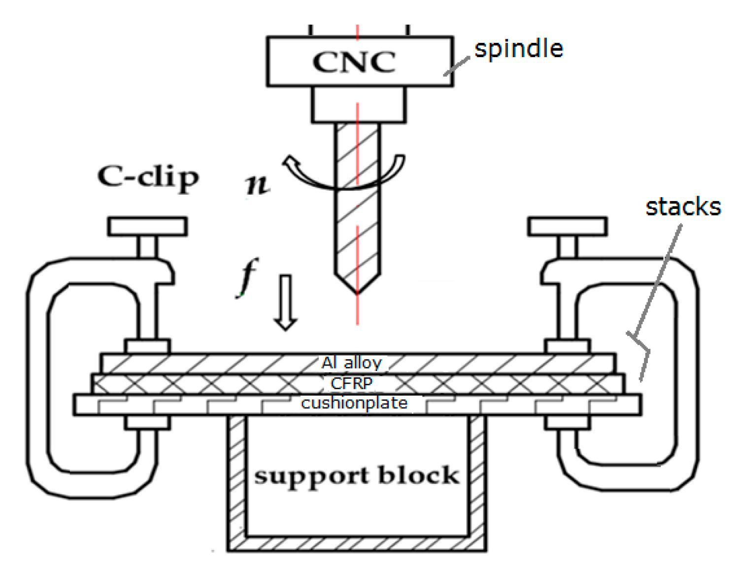
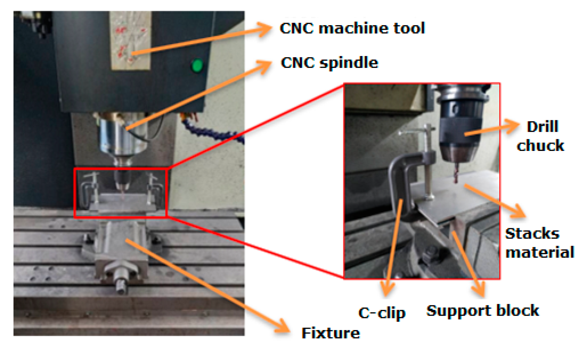
2.1. The Device of Hole Manufacturing
2.2. The Process of Hole Manufacturing
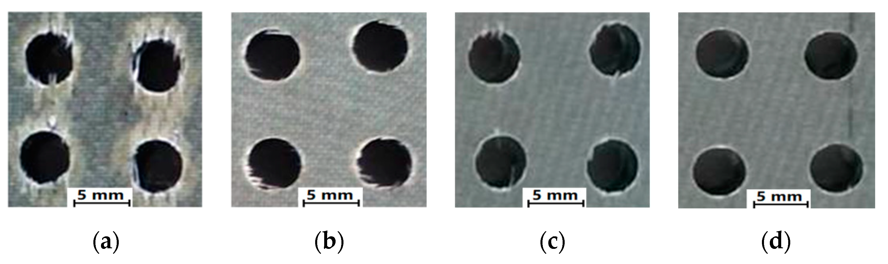
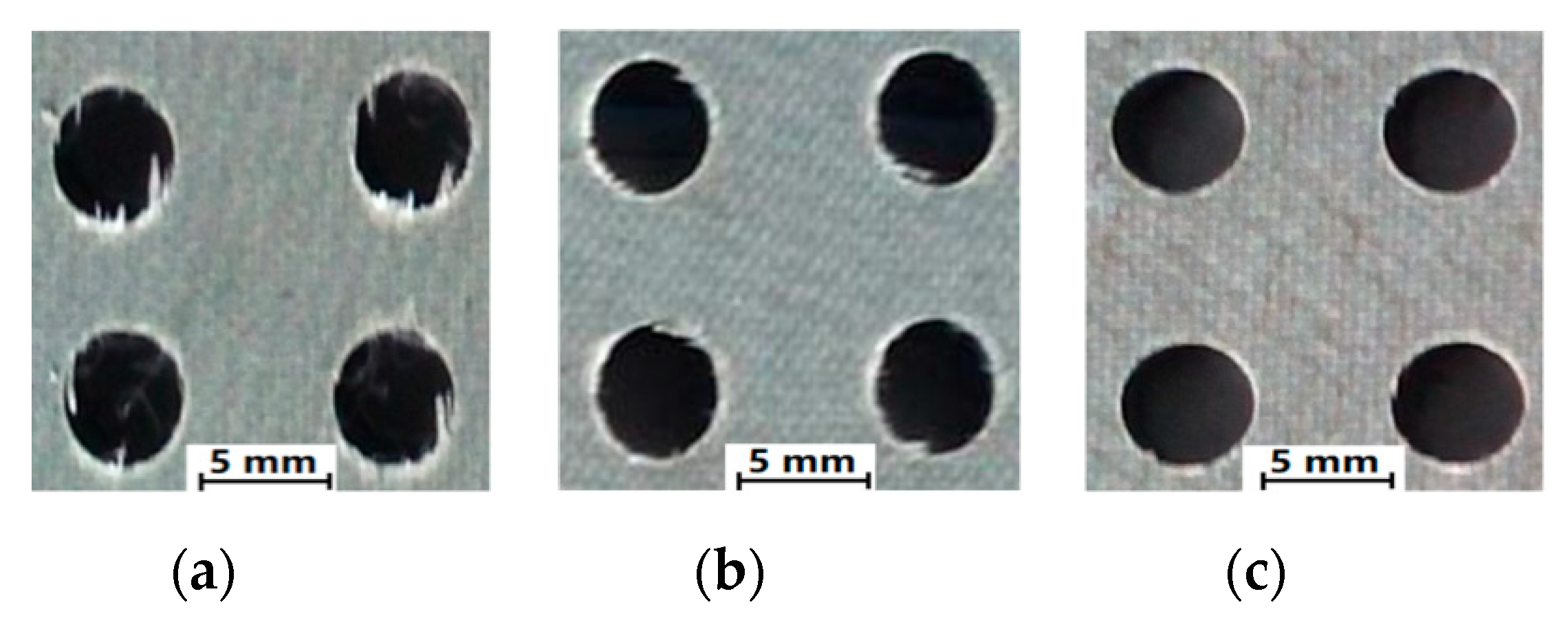
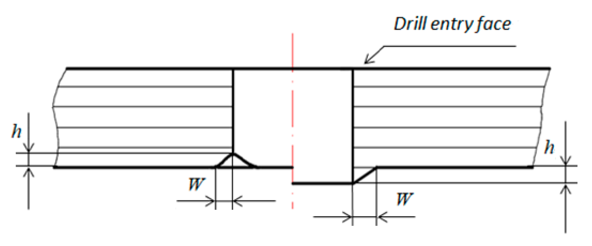
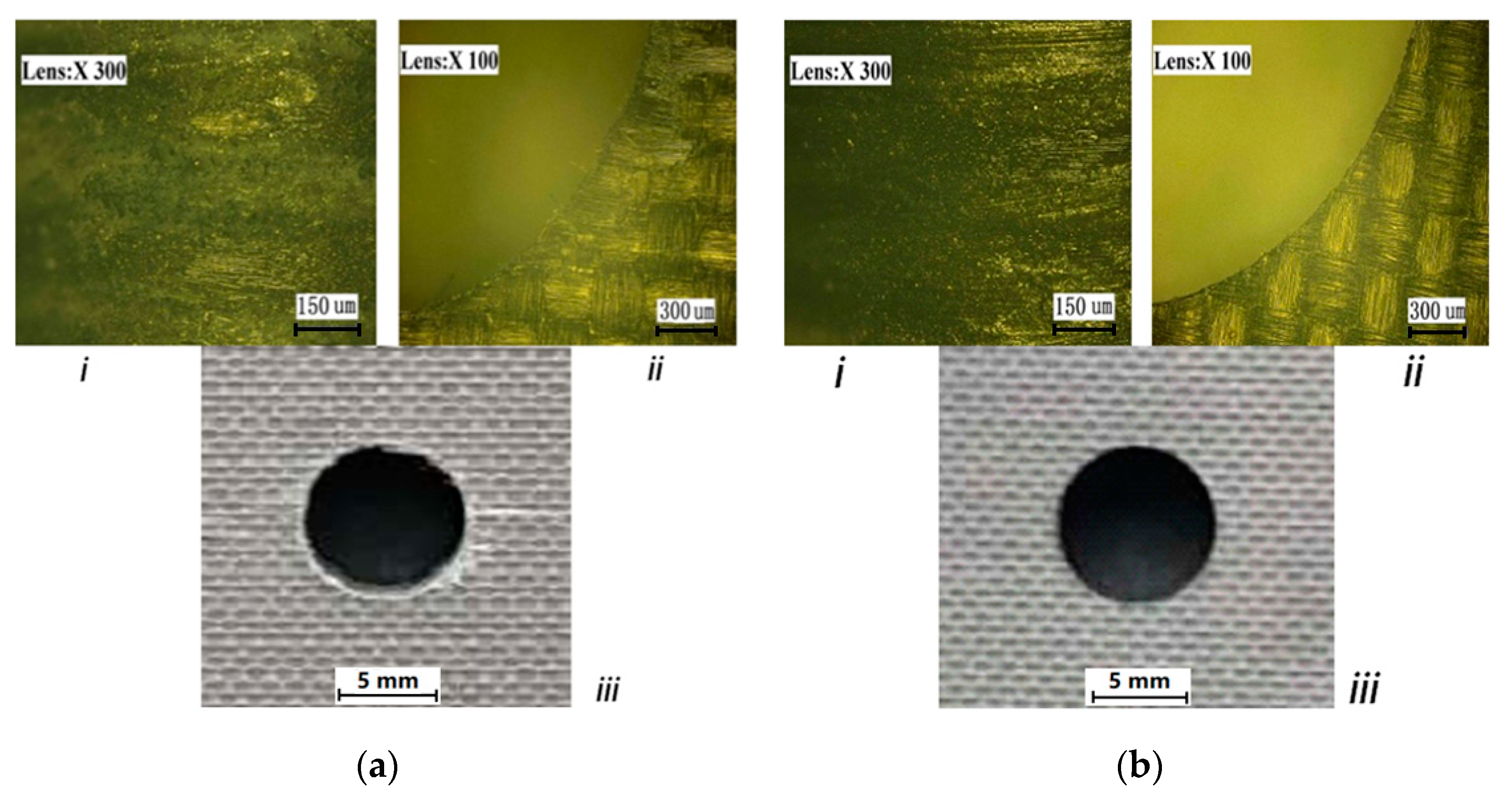
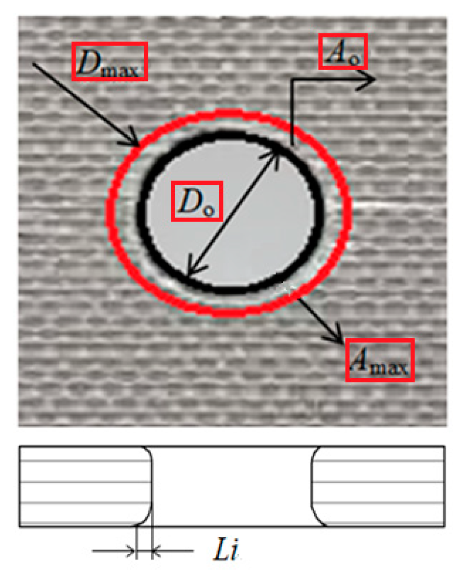
2.3. The Quality Inspection of Holes
3. BP Neural Network Prediction for the Tear Number of Hole
3.1. Introduction of BP Neural Network
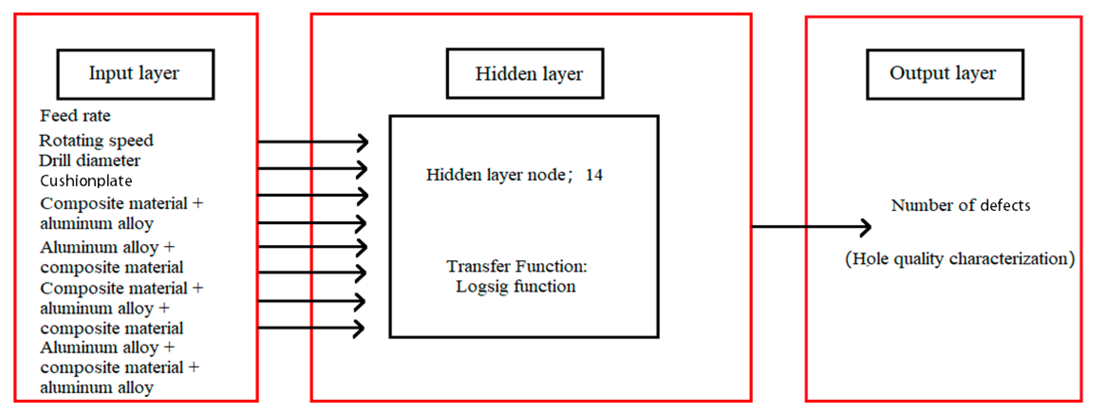
3.2. Establishment of Neural Network Model
3.3. Selection of Hidden Layer Nodes
3.4. Prediction-Influencing Factors of BP Neural Network
4. Training and Verification Experiment of BP Neural Network Model
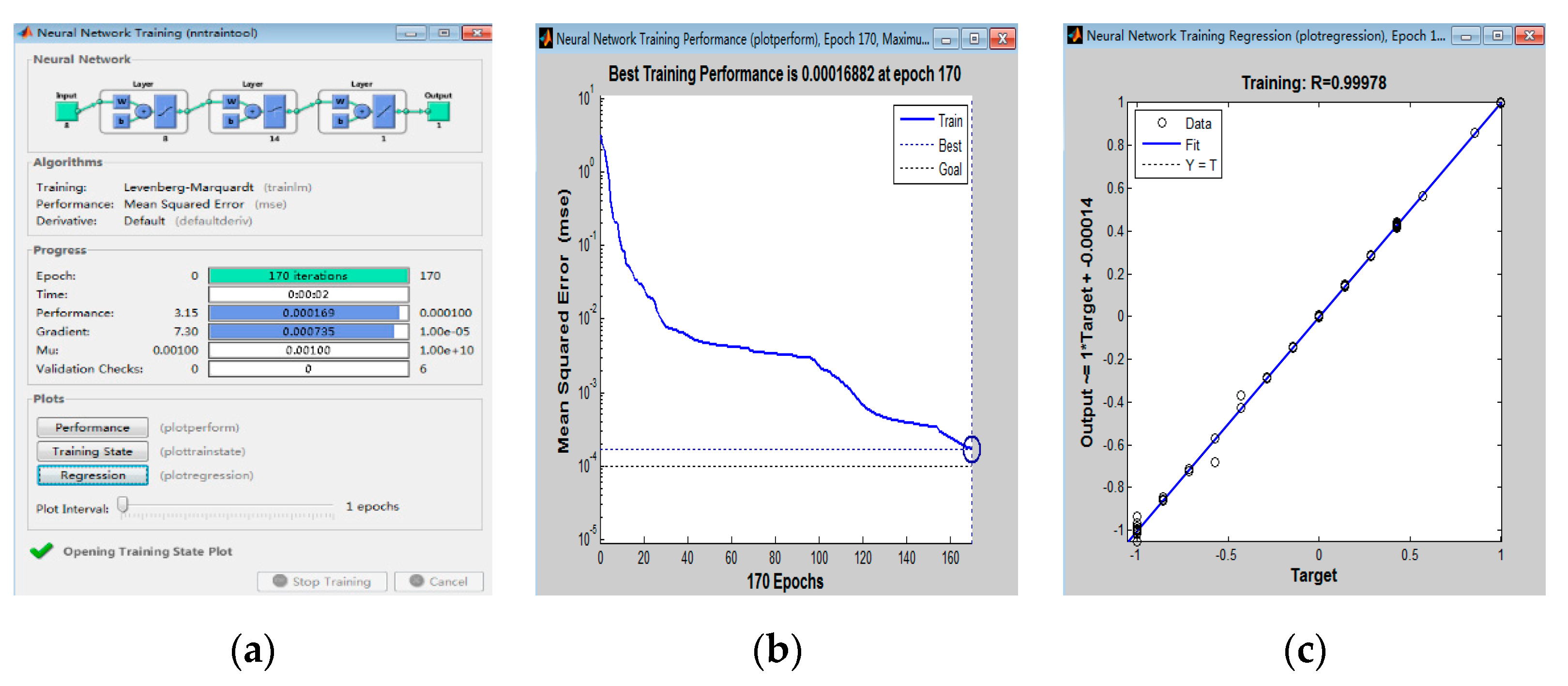
4.1. Model Training
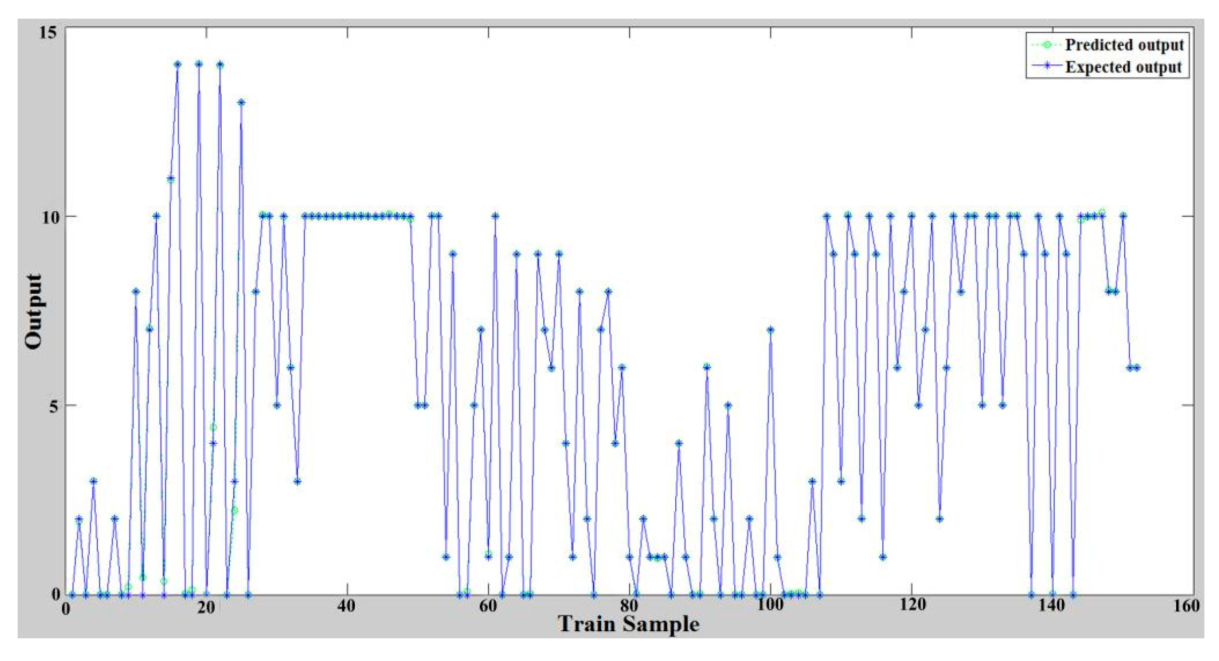
4.2. Results Calculation
4.3. Model Verification
5. Conclusions
- (1)
- The octahedral composite drill and ABS plastic cushion plate with 3 mm thickness were firstly chosen to manufacture all holes. The parameters of input layer were the feed rate, spindle speed, drilling diameter, and cushion plate, with CFRP/Al, Al/CFRP, Al/CFRP/Al, and CFRP/Al/CFRP composites. The output layer parameter was the number of defective holes.
- (2)
- According to the BP neural network prediction model with 8–14–1 three-layer topology, which underwent error correction of 170 steps, the error was reduced to 0.00016882, the regression fit was 0.99978, and the magnitude of training sample fitting error was about 10−2–10−5.
- (3)
- Based on the BP neural network prediction model, the optimized processes of hole-making were obtained. The qualified rate of manufactured holes (Φ3–Φ8 mm) for stack materials composed of T300 CFRP (thickness 3 mm) and 7050-T7 (thickness 2 mm) Al alloy reached 97%.
Author Contributions
Funding
Conflicts of Interest
References
- Chen, Y.; Ge, E.; Fu, Y.; Su, H.; Xu, J. Review and prospect of drilling technologies for carbon fiber reinforced polymer. Acta Mater. Compos. Sin. 2015, 32, 301–316. [Google Scholar]
- Qiu, J.; Chen, J.; Hao, H. Study on the technology of low damage ultrasonic vibration drilling of CFRP. Mech. Sci. Technol. Aerosp. Eng. 2019, 38, 1–8. [Google Scholar]
- Shutao, H.; Haotao, W.Z.; Pan, Z. Finite element analysis on drilling defects of carbon fiber reinforced plastic and aluminum stacks. J. Mater. Sci. Eng. 2019, 37, 493–500. [Google Scholar]
- Dharan, C.K.H.; Won, M.S. Machining parameters for an intelligent machining system for composite laminates. Int. J. Mach. Tools Manuf. 2000, 40, 415–426. [Google Scholar] [CrossRef]
- Davim, J.P.; Reis, P. Study of delamination in drilling carbon fiber reinforced plastics (CFRP) using design experiments. Compos. Struct. 2003, 59, 481–487. [Google Scholar] [CrossRef]
- Mubarak, A.; Joshi, S.C.; Hameed, S.M.T. Palliatives for low velocity impact damage in composite laminates. Adv. Mater. Sci. Eng. 2017, 2017, 1–16. [Google Scholar]
- Hocheng, H.; Tsao, C.C. Comprehensive analysis of delamination in drilling of composite materials with various drill bits. J. Mater. Process. Technol. 2003, 140, 335–339. [Google Scholar] [CrossRef]
- Omar, O.E.E.K.; El-Wardany, T.; Ng, E.; Elbestawi, M.A. An improved cutting force and surface topography prediction model in end milling. Int. J. Mach. Tools Manuf. 2007, 47, 1263–1275. [Google Scholar] [CrossRef]
- Kalla, D.; Sheikh-Ahmad, J.; Twomey, J. Prediction of cutting forces in helical end milling fiber reinforced polymers. Int. J. Mach. Tools Manuf. 2010, 50, 882–891. [Google Scholar] [CrossRef]
- Karpat, Y.; Er, B.; Bahtiyar, O. Drilling thick fabric woven cfrp laminates with double point angle drills. J. Mater. Process. Technol. 2012, 212, 2117–2127. [Google Scholar] [CrossRef] [Green Version]
- Chen, T.; Wang, D.Y.; Gao, F.; Liu, X.L. Experimental study on milling cfrp with staggered pcd cutter. Appl. Sci. 2017, 7, 934. [Google Scholar] [CrossRef] [Green Version]
- Ugoenemuoh, E.; SherifEl-Gizawy, A. Optimal neural network model for characterization of process-induced damage in drilling carbon fiber reinforced epoxy composites. Mach. Sci. Technol. 2003, 7, 389–400. [Google Scholar]
- Karnik, S.R.; Gaitonde, V.N.; Rubio, J.C.; Correia, A.E.; Abrão, A.M.; Davim, J.P. Delamination analysis in high speed drilling of carbon fiber reinforced plastics (CFRP) using artificial neural network model. Mater. Des. 2008, 29, 1768–1776. [Google Scholar] [CrossRef]
- Wang, F.S.; Ma, X.T.; Zhang, Y.; Jia, S.Q. Lightning damage testing of aircraft composite-reinforced panels and its metal protection structures. Appl. Sci. 2018, 8, 1791. [Google Scholar] [CrossRef] [Green Version]
- Ding, S.; Su, C.; Yu, J. An optimizing bp neural network algorithm based on genetic algorithm. Artif. Intell. Rev. 2011, 36, 153–162. [Google Scholar] [CrossRef]
- Li, J.; Cheng, J.H.; Shi, J.Y.; Huang, F. Brief Introduction of Back Propagation (BP) Neural Network Algorithm and Its Improvement; Springer: Berlin/Heidelberg, Germany, 2012. [Google Scholar] [CrossRef]
- Geng, X.G.; Lu, S.Z.; Jiang, M.S.; Sui, Q.; Lv, S.; Xiao, H.; Jia, Y.; Jia, L. Research on fbg-based cfrp structural damage identification using bp neural network. Photon. Sens. 2018, 8, 168–175. [Google Scholar] [CrossRef] [Green Version]
- Zou, W.; Li, Y.; Tang, A. Effects ofthe number of hidden nodes used in a structured-based neural network on the reliability of image classification. Neural Comput. Appl. 2009, 18, 249–260. [Google Scholar] [CrossRef] [Green Version]
- Rahme, P.; Landon, Y.; Lagarrigue, P.; Piquet, R.; Lachaud, F.; Marguet, B.; Bourriquet, J.; Le Roy, C. Drilling of thick composite structures state of the art. SAE Int. 2006. [Google Scholar] [CrossRef]
- Saghizadeh, H.; Dharan, C.K.H. Delamination fracture toughness of graphite and Aramid epoxy composites. ASME J. Eng. Mater. Technol. 1986, 108, 290–295. [Google Scholar] [CrossRef]
- Childs, T.H.C.; Dirikolu, M.H.; Maekawa, K. Modelling of friction in the simulation of metal machining. Tribol. Interface Eng. 1998, 34, 337–346. [Google Scholar]
- Hocheng, H.; Dharan, C.K.H. Delamination during drilling in composite laminates. ASME J. Eng. Ind. 1990, 112, 236–239. [Google Scholar] [CrossRef]
- An, Q.; Cai, X.; Xu, J.; Chen, M. Experimental investigation on drilling of high strength T800s/250F CFRP with twist and dagger drill bits. Int. J. Abras. Technol. 2014, 6, 183–196. [Google Scholar] [CrossRef]


| Drill Bit | Appearance Picture | Drill Bit | Appearance Picture |
|---|---|---|---|
| Three-pointed two-edged drill |  | Reamer drill |  |
| Double-edged drill |  | Octahedral composite drill |  |
| Hole Diameter | h (Maximum) | W (Maximum) |
|---|---|---|
| 3.18 mm | 0.36 mm | 1.27 mm |
| 3.97 mm | 0.36 mm | 2.54 mm |
| 4.76 mm | 0.36 mm | 2.54 mm |
| 6.35 mm | 0.36 mm | 2.54 mm |
| 7.94 mm | 0.36 mm | 3.04 mm |
| Node | 7 | 8 | 9 | 10 | 11 | 12 | 13 | 14 | 15 | 16 | 17 |
| Error | 325 | 197 | 123 | 62 | 167 | 135 | 100 | 28 | 57 | 84 | 224 |
| Input Vector | Feed Rate (mm/r) | Spindle Speed (r/min) | Drilling Diameter (mm) | CFRP (3 mm) (Y1, N0) | Al (2 mm) (Y1, N0) | CFRP (3 mm) (Y1, N0) | Al (2 mm) (Y1, N0) | Cushion Plate (Y1, N0) |
|---|---|---|---|---|---|---|---|---|
| Level I | 0.007 | 3000 | 3.26 | 0/1 | 0/1 | 0/1 | 0/1 | 0/1 |
| Level II | 0.02 | 5000 | 4.81 | 0/1 | 0/1 | 0/1 | 0/1 | 0/1 |
| Level III | 0.04 | 7000 | 7.92 | 0/1 | 0/1 | 0/1 | 0/1 | 0/1 |
| Test No. | Feed Rate (mm/r) | Spindle Speed (r/min) | Drilling Diameter (mm) | CFRP (3 mm) (Y1, N0) | Al (2 mm) (Y1, N0) | CFRP (3 mm) (Y1, N0) | Cushion Plate (Y1, N0) | Actual Number of Defects | Prediction Number of Defects | Absolute Value of Error |
|---|---|---|---|---|---|---|---|---|---|---|
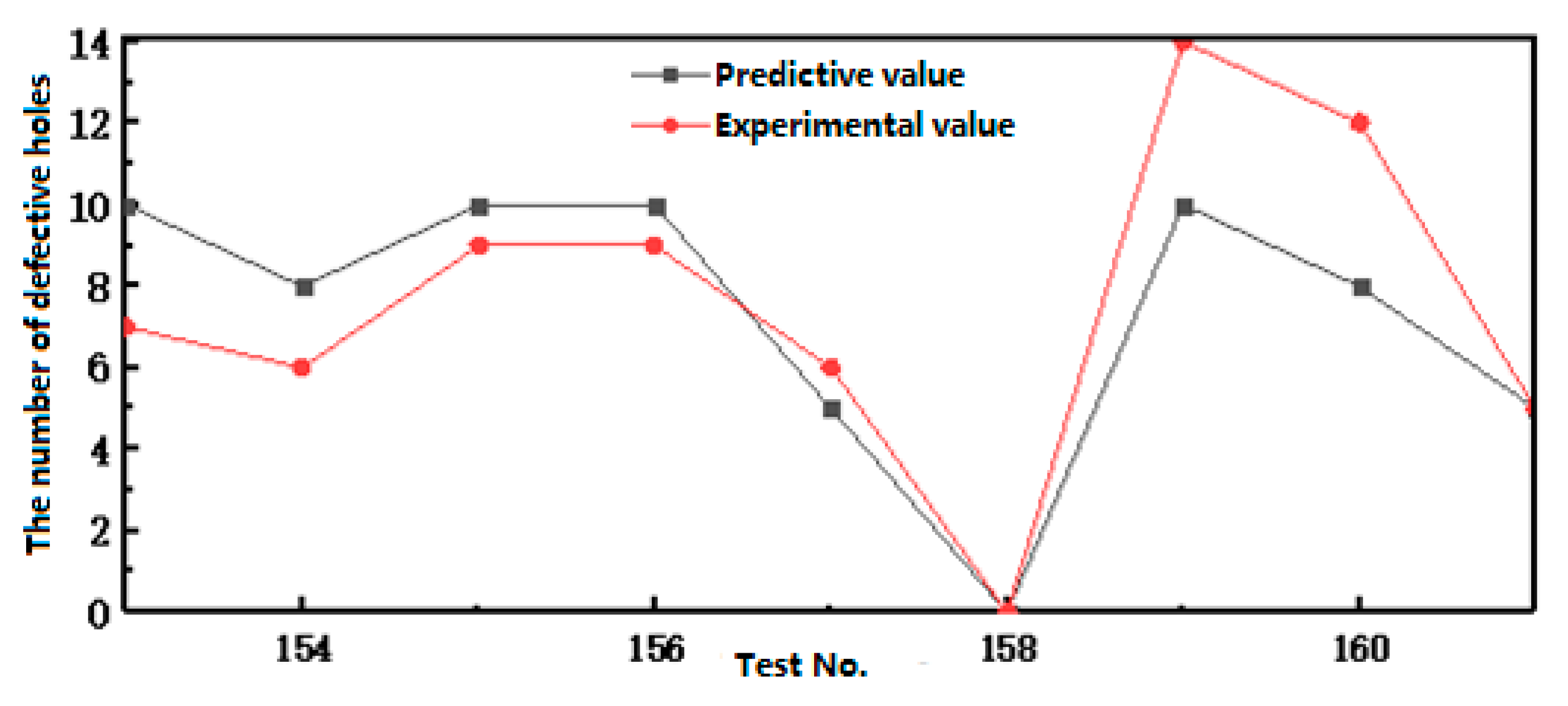
| 153 | 0.04 | 3000 | 3.26 | 1 | 1 | 1 | 1 | 10 | 7 | 3 |
| 154 | 0.04 | 3000 | 4.81 | 1 | 1 | 1 | 1 | 8 | 6 | 2 |
| 155 | 0.04 | 3000 | 7.92 | 1 | 1 | 1 | 1 | 10 | 9 | 1 |
| 156 | 0.04 | 5000 | 3.26 | 1 | 1 | 1 | 1 | 10 | 9 | 1 |
| 157 | 0.04 | 5000 | 4.81 | 1 | 1 | 1 | 1 | 5 | 6 | 1 |
| 158 | 0.04 | 5000 | 7.92 | 1 | 1 | 1 | 1 | 0 | 0 | 0 |
| 159 | 0.04 | 7000 | 3.26 | 1 | 1 | 1 | 1 | 10 | 14 | 4 |
| 160 | 0.04 | 7000 | 4.81 | 1 | 1 | 1 | 1 | 8 | 12 | 4 |
| 161 | 0.04 | 7000 | 7.92 | 1 | 1 | 1 | 1 | 5 | 5 | 0 |
| Optimization No. | Feed Rate (mm/r) | Spindle Speed (r/min) | Drilling Diameter (mm) | CFRP (3 mm) (Y1, N0) | Al (2 mm) (Y1, N0) | CFRP (3 mm) (Y1, N0) | Al (2 mm) (Y1, N0) | Cushion Plate (Y1, N0) | Prediction Number of Defects |
| P1001 | 0.007 | 5500 | 6.35 | 1 | 1 | 0 | 0 | 0 | 0 |
| P1002 | 0.02 | 3300 | 4.83 | 0 | 1 | 1 | 0 | 1 | 0 |
| P1003 | 0.04 | 7000 | 3.26 | 0 | 1 | 1 | 1 | 0 | 0 |
| P1004 | 0.007 | 7000 | 7.94 | 1 | 1 | 1 | 0 | 1 | 0 |
© 2020 by the authors. Licensee MDPI, Basel, Switzerland. This article is an open access article distributed under the terms and conditions of the Creative Commons Attribution (CC BY) license (http://creativecommons.org/licenses/by/4.0/).
Share and Cite
Jiao, A.; Zhang, G.; Liu, B.; Liu, W. Prediction of Manufacturing Quality of Holes Based on a BP Neural Network. Appl. Sci. 2020, 10, 2108. https://doi.org/10.3390/app10062108
Jiao A, Zhang G, Liu B, Liu W. Prediction of Manufacturing Quality of Holes Based on a BP Neural Network. Applied Sciences. 2020; 10(6):2108. https://doi.org/10.3390/app10062108
Chicago/Turabian StyleJiao, Anyuan, Guofu Zhang, Binghong Liu, and Weijun Liu. 2020. "Prediction of Manufacturing Quality of Holes Based on a BP Neural Network" Applied Sciences 10, no. 6: 2108. https://doi.org/10.3390/app10062108