Article

Process Simulation of Co-Gasification of Raw Municipal Solid Waste and Bituminous Coal in CO2/O2 Atmosphere

1
Institute of Combustion and Thermal Systems, School of Mechanical, Electronic and Control Engineering, Beijing Jiaotong University, Beijing 100044, China
2
School of Mechanical and Power Engineering, Haibin College of Beijing Jiaotong University, Huanghua 061199, China
*
Author to whom correspondence should be addressed.
Appl. Sci. 2020, 10(6), 1921; https://doi.org/10.3390/app10061921
Submission received: 14 February 2020 / Revised: 6 March 2020 / Accepted: 8 March 2020 / Published: 11 March 2020
(This article belongs to the Special Issue Intensified Conversion of Organic Waste into Biogas)

Abstract

:
An integrated CO2/O2 co-gasification system of municipal solid waste (MSW) and bituminous coal (BC) with CO2 capture was developed and simulated by the Aspen plus, which mainly consisted of three processes: air separation unit, co-gasification system, and CO2 absorption unit. In addition, raw syngas composition, cold gas efficiency (CGE), and overall energy efficiency (OEE) of the entail system were evaluated in detail with respect to the main operating parameters (gasification temperature, T; oxygen equivalence ratio, Ro; mole of CO2 to carbon ratio, Rc; and the MSW blending ratio, RM). The results indicated that the addition of BC improved the gasification of MSW. Higher gasification temperature increased CGE and OEE. Increasing the Rc ratio led to the decrease of H2 mole fraction due to the enhanced reverse water-gas shift reaction. In addition, the CGE and OEE of the system decreased with increasing RM. From the analyses of the parameters, the most optimal operating conditions were set as T = 900 °C, Ro = 0.2, Rc = 0.5, and RM = 0.6, and the corresponding OEE of the system reached 0.57. The system can achieve a large processing capacity of MSW at the cost of the efficiency loss of this condition.

1. Introduction

The total amount of municipal solid waste (MSW) in China reached 191.4 million tons in 2015 [1], and production is predicted to increase to 480 million tons in 2030 as a result of economic development and a growing population [2,3,4]. This has caused very serious environmental and social problems. Among these MSW disposal technologies, the incineration technology is widely applied due to its advantages of large reducing capacity and energy recovery for power generation. However, traditional direct incineration entails high investment and operating costs while producing a wide variety of pollutants. Gasification is becoming an increasingly attractive alternative to convert solid waste into a clean syngas (CO, H2, and CH4) because it can reduce emissions of carcinogens, such as dioxins and furans [5], and also achieve higher overall efficiency and lower investment cost than direct combustion [6]. Despite its many advantages, there are some inherent disadvantages, such as the high moisture, lower heating value, and complexity of the MSW components. These drawbacks can lead to a lower calorific value of syngas, which may also contain impurities that restrict the development of MSW gasification technology.
Because of the abundant fossil fuel consumption in China, the coal has a higher heating value and can be co-gasified with MSW to improve the syngas quality, and the relatively high temperature of the co-gasification process can also accelerate the decomposition of waste pollutants. Therefore, the co-gasification of MSW and coal has potential as a promising method to overcome the above disadvantages. On the other hand, as a nonrenewable resource, coal will be exhausted in the future, and co-gasification of MSW and coal can also reduce the fossil fuel consumption and emissions. Besides, the co-gasification technology has some other advantages that were established by the research of Emami-Taba et al. [7], such as reduced fossil-based CO2, NOx, and SOx production; higher production of CO, CH4, and hydrocarbons; increased carbon conversion; and reduction in H2S and NH3 production compared to coal gasification alone. Historically, there have been a few studies that have focused on the performance of MSW and coal co-gasification. Pinto et al. [8,9] performed a co-gasification experiment on coal blending with wastes and researched the effects of catalysts on the tars, heavy metals, and sulfur produced from co-gasification; the gasifying agent was a mixture of steam and oxygen. It was found that the presence of catalysts facilitates the reduction of hydrocarbons and tars, heavy metals, and H2S. Zaccariello et al. [10] investigated the overall performance efficiency of the air co-gasification process (coals, plastics, and wood) by a pre-pilot scale bubbling fluidized bed gasifier. They found that the lower heating value (LHV) progressively increased from 5.1 to 7.9 MJ/Nm3 when adding the plastic waste proportion. Pinto et al. [11] performed co-gasification experiments on coals of different grades mixed with different types of biomass waste, and found that co-gasification is beneficial in reducing the negative characteristics of coals; the type of feedstock was a key factor for initial syngas composition. Ramos et al. [12] reviewed the co-gasification of waste and biomass to energy conversion, and concluded that co-gasification was beneficial in enhancing product quality and yield compared with wastes gasification alone; additionally, they attested its environmental-friendly character with lower greenhouse gas emissions. The fluidized beds were the most suitable reactors for co-gasification. Hu et al. [13] set an innovative three-stage gasifier system for co-gasification of MSW with high alkali coal char. The effects of temperature and equivalence ratio on the concentration of tar and HCl have been evaluated experimentally. It was found that the lowest gasification temperature (800 °C) was conducive to the removal of HCl from syngas and the rising equivalence ratio can decrease the tar. Cormos [14] investigated the techno-economic and environmental analysis of the coal and MSW co-gasification power system with carbon capture, and found that the net power efficiency and carbon capture rate were 35.73% and 92.88%, respectively, which indicated that the co-gasification of MSW and coal is feasible in economic terms. Based on the above publications, these studies mainly investigated various parameters, including waste composition, gasification temperature, and gasifying agents, on the co-gasification performance; the selection of gasifying agents has an important influence on the quality of syngas.
Recently, the use of CO2 as the gasifying agent is gaining more and more attention due to the opportunity utilization of the greenhouse gas in the gasification process [15]. Simultaneously, the application of gasifying agents (CO2 and O2) is also beneficial in reducing the emission of NOx formation by preventing the contact between the gasified products and nitrogen [16], and the dilution effect of nitrogen for the syngas can be minimized. Many studies have been conducted to investigate the performance of the co-gasification process in CO2 atmosphere, and coal and biomass are typically used as the feedstock. Kuo et al. [17] constructed the co-gasification system blending coal and biomass and performed thermodynamic analysis using Aspen plus. They found that the addition of CO2 can effectively improve the energy conversion efficiency and exergy efficiency, and co-gasification of torrefied biomass and coal blends can suppress CO2-specific emissions. Adnan et al. [18] used an equilibrium model to investigate the performance of an integrated co-gasification of coal and microalgae with CO2 utilization. Adnan et al. concluded that the increase of biomass/coal ratio increased gasification system efficiency and decreased cold gas efficiency, and the synergetic effect of Indonesian coal and biomass exhibited optimum gasification performance. In addition, Wang et al. [19] investigated the characteristics of syngas production from the co-gasification of waste tire and pine bark in CO2 atmosphere by the fixed-bed reactor at 800 and 900 °C. They found that the peak flow rate of H2, CO, and total syngas increased with increasing pine bark mixed ratio, but CmHn decreased at the two temperatures. Besides, the syngas yield of syngas at 800 °C was lower than that at 900 °C for a certain blend ratio. Kan et al. [20] conducted CO2 co-gasification experiments of horticultural waste and sewage sludge with addition of ash from waste as catalyst in a fixed-bed lab-scale gasifier, and found that the increase in agent flow improves cold gas efficiency, whereas it negatively affects the higher heating value of syngas and CO2 reduction ratio.
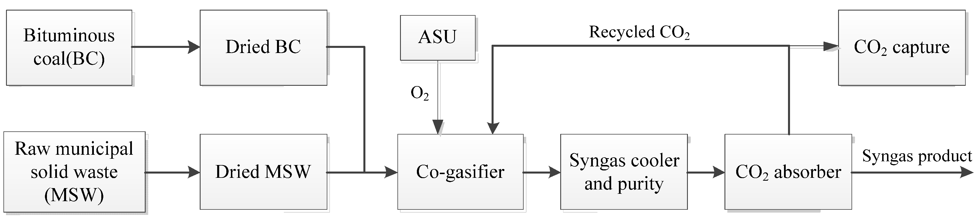
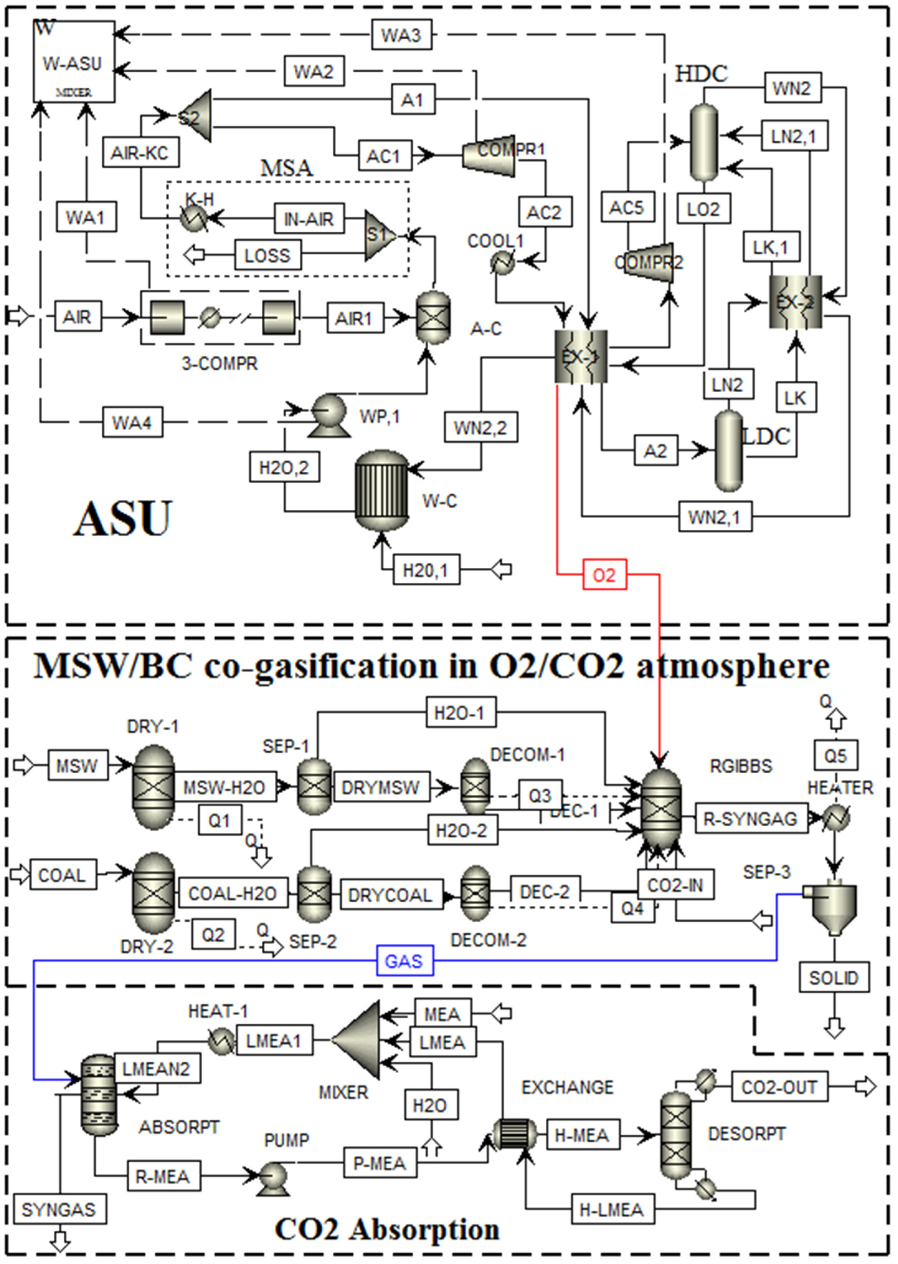
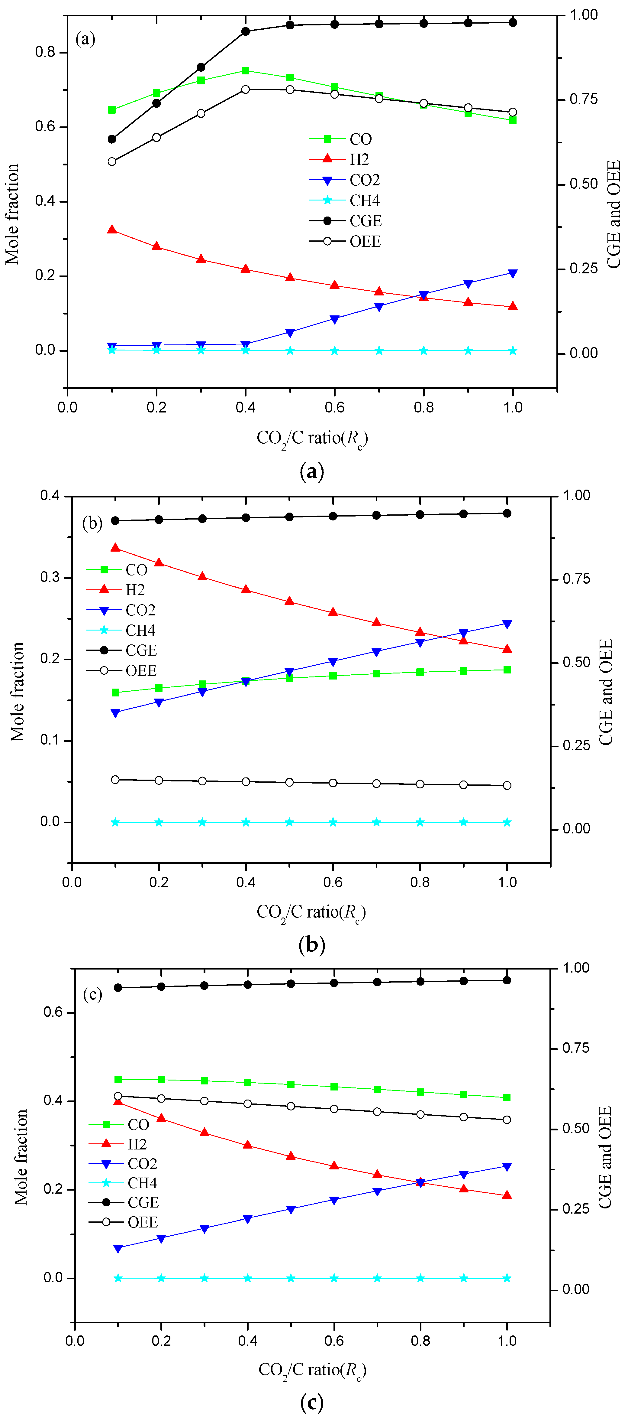
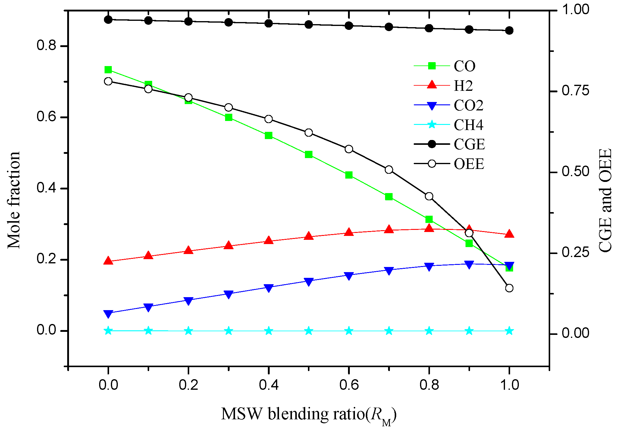
Although some researches are focused on the CO2 co-gasification performance of coal and biomass or other solid fuels, most focused on the biomass/coal co-gasification aspects. However, there are no enough detailed investigations on the co-gasification of MSW and bituminous coal (BC) in CO2/O2 atmosphere, especially for the analysis of its integrated system. Therefore, in this study, an innovative integrated co-gasification system of raw MSW and BC with CO2 recycle and capture is developed and simulated by using a thermodynamics equilibrium model. In addition, the optimum operating parameters of gasification process, such as gasification temperature, oxygen equivalence ratio, mole of CO2 to carbon ratio, and MSW blending ratio are investigated in detail. The obtained results can provide a better reference for MSW harmless disposal and resource recycling with minimum CO2 emission.

2. Materials and Methods

2.1. Process Description

The schematic block diagram of an integrated co-gasification system of BC blended with MSW is presented in the Figure 1, which consists mainly of three processes: (1) air separation unit (ASU), (2) co-gasification of MSW and BC, and (3) CO2 absorption unit and syngas treatment. The mixtures of MSW and Shenmu BC act as the feedstock, and their proximate and the ultimate analyses are displayed in Table 1. The raw MSW and BC are first dried and then sent to be co-gasified in a fluidized bed gasifier using O2 and CO2 as the gasifying agents. Moreover, the H2O component from the raw MSW drying process can also act as an agent to improve the BC gasification. The main chemical reactions for the MSW/BC co-gasification process are illustrated in the Table 2. Among them, the R1 reaction represents the drying process of MSW/BC, and R2 reaction stands for the pyrolysis process of dried MSW/coal, which starts at above 230 °C [21], where the char and volatile matters are released and participate in gasification reaction. The R3-R11 reactions represent a series of gasification reactions, including heterogeneous (R3-R6) and homogeneous reactions (R7-R11). The required oxygen can be obtained by the ASU, which uses cryogenic technology due to its high separation efficiency and relatively low cost for large-scale oxygen production [22]. After being cooled and purified, the raw syngas enters the CO2 absorption unit to remove CO2. Some of the CO2 absorbed is recycled in the gasifier to act as the agent and the rest is captured. The syngas leaving the absorption is treated as syngas product.

2.2. System Modeling

The simulation of the integrated co-gasification system of MSW and BC in CO2/O2 atmosphere is developed by using the Aspen plus software, and the detailed flowchart is displayed in Figure 2. In the ASU subsystem, a standard double column process is utilized in the O2 production, which is also widely used by the ASU manufacturers [29]. After three-stage centrifugal compression, the feeding air is first purified by the molecular sieve adsorber (MSA) and is then divided into two streams. One stream directly enters into the low distillation column (LDC) after heat exchanger (EX-1), and another stream first enters into the expander and then enters the high distillation column (HDC). The separation of air is achieved in these two distillation columns, and finally the oxygen discharged from the HDC is re-heated in EX-1 exchanger and sent to the co-gasification chamber. By the calculation and analysis of power consumption in the ASU, the energy consumption of unit produced oxygen is 0.324 kWh/Nm3 when the mole fraction of oxygen is 95%; approximate result obtained from literature [21].
In the co-gasification subsystem of MSW and BC, a total of 100 kg/h blends of feed fuels are used in all cases. The MSW and BC first are dried in the RYield block, and the released H2O component is directly sent to the gasification unit. The gasification process is modeled by the RYield and RGIBBS blocks. The devolatilization process of MSW/BC is achieved by this RYIELD block, which is used to model a reactor when the reaction stoichiometry and kinetics are unknown [30]. Its main function is to decompose the fuel (non-conventional) into the conventional elements, including moisture, hydrogen, oxygen, nitrogen, sulfur, chlorine, ash, and char (carbon-solid). An internal FORTRAN subroutine is applied to control the progress of this pyrolysis reaction. Meanwhile, the required heats are provided by the gasification unit. The RGIBBS reactor is used to model the gasification reactions in the gasifier as shown in Table 2, which can calculate the chemical equilibrium and phase equilibrium by minimizing the Gibbs free energy of the system [31]. The related mathematical model is shown as follows,
M i n G , G = j = 1 S n j c G j 0 + j = S + 1 M l = 1 P n j l G j l
i = 1 I m i Δ H R , 298 0 + i = 1 I m i Δ H R , T ( R , i ) = j = 1 J m j Δ H P , 298 0 + j = 1 J m j Δ H P , T ( P , j ) + Q L
where G is the Gibbs free energy of system; S is the number of single phase; M is the total number of phases; P is the number of components; G j 0 is defined as the standard Gibbs energy of component j; mi and mj are the mole flows of reactant i and product j, respectively; Δ H 298 0 and ΔHT denote to the standard enthalpy of formation and the enthalpy at T; and QL refers to the heat loss of reaction system. Then, the raw syngas is purified and the ash and unconverted carbon are removed after being cooled. At last, the product gas is sent to the CO2 absorption unit to remove the CO2.
Monoethanolamine (MEA) is applied as the absorbent in the CO2 absorption unit, which is widely used as the CO2 capture for the natural gas treatment [32]. As shown in Figure 2, the raw syngas enters the absorption tower to achieve the removal of the CO2 and is discharged from the top of the tower to obtain the syngas production. Then, the MEA solution contained in CO2 is sent to the desorption tower to release the CO2 after pressurization and heat exchange. The MEA solution discharged from desorption tower is recycled to use after cooling down through the heat exchanger. In this work, the CO2 capture efficiency is set as 90% [33]. The captured energy consumption of unit CO2 is 3 MJ/kg by simulation calculation, which is compared with the reported data of Chaiwatanodom [34] and Jassim [35], shown in Table 3. It can be obtained that the simulation result is a good agreement with the literature results.

2.3. Assumptions and Stream Parameters

The main assumptions in co-gasification process of MSW and BC are as follows.
(1)
The entail gasification process is steady state and all considered reactions can achieve chemical equilibrium [36,37,38].
(2)
Ash is an inert component and does not participate in any chemical reactions; it is eventually discharged as solid residue.
(3)
The loss of pressure drop of the entail system is not considered.
Although there are some slightly differences between these assumptions and the practical process conditions, they are considered reasonable and acceptable by the by comparison in Section 3.1. The other main operating parameters of co-gasification system are shown in Table 4. The Peng and Robinson equation of state is applied to calculate the property method for the simulation [39]. Due to the unconventional component for the MSW and BC, the enthalpy and the density of fuel are determined with the HCOALGEN mode and DCOALIGT model, respectively [40].

2.4. Performance Evaluation

The gasification temperature T, oxygen equivalence ratio Ro, mole of CO2 to carbon ratio, Rc and the MSW blending ratio RM are four significant parameters in this co-gasification process; they can be expressed as follows,
R o = m actO 2 / m fuel m stoO 2 / m fuel
R c = m CO 2 / 44 y c m fuel / 12
R M = m MSW m MSW + m coal
where mactO2 and mstoO2 represent the actual and stoichiometric oxygen mass in gasifying agents, respectively; yc is the carbon content in the fed fuel; mCO2 is the recycled input CO2 mass; and mMSW and mcoal are the mass flows of MSW and coal, respectively.
The lower heating value (LHV) of the product syngas is an important index to evaluate the quality of the product gas, which is defined as Equation (6) [41]:
L H V g a s = 282993 X C O + 241827 X H 2 + 802303 X C H 4
where, XCO, XH2, and XCH4 denote to the molar fraction of species CO, H2, and CH4, respectively. In addition, the cold gas efficiency (CGE) and the overall energy efficiency (OEE) of this system are calculated by the Equations (7) and (8) [42].
C G E = m s y g L H V g a s m f u e l L H V f u e l
O E E = m s y n L H V g a s + Q 5 Q 1 Q 2 m f u e l L H V f u e l + W A S U + Q C A
where msyn and mfuel are mass flow of product syngas and fed fuel, respectively; Q1 and Q2 denote to the heats required for MSW and BC drying, respectively; Q5 is the released heat from syngas cooling; WASU is the energy consumption for O2 production; and QCA refers to the heat amount for CO2 absorption unit.

3. Results and Discussion

3.1. Model Validation

The model validation of the co-gasification system was carried out by comparing the composition of the product gas obtained from the developed model of this work with the literature results reported by Renganathan [43] and Adnan [18]. The properties of fuels and all operating parameters were set identical to that of the literatures. The comparison of the mole fractions of product gas at two different gasification temperatures (800 and 1000 °C) are displayed in Table 5. It can be seen that our simulation results can better match the literature values, and the errors of the main component (H2, CO, CO2, and CH4) are in the range of 4%. This indicates that the chemical equilibrium model established in this work has good reliability, which can be applied to simulate the co-gasification process of MSW and BC.

3.2. Effects of Gasification Temperature

The gasification temperature T is a very important operating parameter for the coal/MSW gasification, which has a significant influence on the composition of syngas product and system performance [44]. Therefore, to investigate the effects of gasification temperature, some simulations were carried out from range of 750 to 1100 °C at a certainly operating condition of Ro = 0.2 and Rc = 0.5. The raw syngas composition and system performance for the individual BC, MSW, and blend of RM = 0.6 are displayed in Figure 3. Based on Figure 3a, the mole fraction of CO gradually increased, whereas that of CO2 and H2 all decreased with increasing gasification temperature. It may because the Boudouard reaction (R4) and steam reforming reaction (R5) are enhanced which are benefited from high temperature. In addition, the syngas composition of CO, H2, and CO2 tended to be in a stable state at gasification temperature higher than 900 °C. This stability indicates that all reactions are close to the equilibrium at a certain amounts of gasifying agent (O2 and CO2) when the gasification temperature is ~900 °C [45]. This can be further confirmed by the variety of the CGE and OEE, which also perform the increasing trends and reach the plateau at 900 °C.
However, the effects of gasification temperature for individual MSW showed a great difference compared with that of BC from the Figure 3b. Although the change trends of all syngas composition mole fraction were similar to the increasing of the gasification temperature, the amount of H2 component was the largest for the MSW gasification and the change in amount of H2 was also larger compared with that of BC gasification, approximately 6%. This is mainly because the MSW consists of more moisture component, and the H2O released by the MSW drying process can act as an extra gasifying agent to improve the H2 generation reaction. Moreover, the OEE of the MSW gasification system was between 13.8% and 14.6%, as the gasification temperature increase was much lower than that of BC. This might be because the carbon content and heating value of MSW is lower than that of BC, resulting in lower syngas (CO+H2) production. In addition, for the co-gasification process of RM = 0.6 blending ratio, it can been seen that the syngas composition, CGE, and OEE of this system is between that of BC and MSW, which indicates that the addition of BC is beneficial to improve gasification performance of MSW.

3.3. Effects of Oxygen Equivalence Ratio Ro

Oxygen equivalence ratio, Ro, refers to the amount of O2 supplied to the gasifier, and it is also a crucial parameter that effects the syngas composition. In this simulation, the Ro was varied from 0.1 to 1.0 by adjusting the oxygen feed rate, and the effects of Ro on the syngas composition and system performance are shown in Figure 4. It can be found that the mole fraction of CO, H2, and CH4 gradually decreased, whereas that of CO2 had a large upward trend, which implies that the increase of supplied oxygen contributes to the enhancement of the R7 and R8 reactions. Li et al. [46] carried out the co-gasification experiment of coal and biomass to research the effect of equivalence ratio and obtained the similar conclusion. Based on Figure 4a, the CGE and OEE of system showed a trend of increasing, decreasing, and then reaching a maximum at Ro = 0.2. This indicates that an equivalence ratio of 0.2 is very suitable for the gasification characteristics of individual BC. In addition, the CGE and OEE for MSW and the blends with RM = 0.6 consistently decreased with increasing Ro. This trend might occur because the presence of oxygen promotes the combustion reaction of combustible gases, resulting in the reduction of the syngas heating value. In addition, it can be found that the OEE reduction extent of the system was less than that of CGE for three samples. This is because the amount of syngas production decreases at higher equivalence ratio, but the released heat Q5 of the entail system increases, which eventually leads to slower decline of the OEE.

3.4. Effects of CO2 to Carbon Ratio Rc

In this work, the co-gasification of MSW and BC in CO2/O2 atmosphere is studied; the CO2 flow rate into the gasifier is a key parameter for gasification performance. The range of Rc is set to 0.1 to 1.0 by adjusting the CO2 fed flow rate at a constant fuel feed rate of 100 kg/h. Besides, the gasification temperature and Ro are kept constant. The effect of Rc on raw syngas composition and system performance for three samples is presented in Figure 5. For the individual BC gasification, with the increasing of Rc ratio, the mole fraction of CO first increased then slightly decreased when the demarcation point was at the position Rc = 0.4, whereas the mole fraction of CO2 remained stable when Rc was less than 0.4, and subsequently increased. This indicates that the supplied CO2 is consumed and the Boudouard reaction R4 is strengthened. Further, the mole fraction of CO2 was affected by the supplied Rc ratio, and the final composition fraction of the producer gas was also dominated by the CO2 flow rate [47]. The mole fraction of H2 decreased for gasification of all three samples. This decrease may be because the higher Rc ratio supports the reverse water-gas shift reaction R9, resulting in converting CO2 and H2 into CO and H2O.
According to the Figure 5a, the CGE of BC gasification system sharply increased when the Rc was less than 0.5, and subsequently increased smoothly. Concurrently, the OEE of system showed a trend of increasing first and then decreasing, and obtained the maximum at approximately Rc = 0.5. Therefore, the Rc of 0.5 can be regarded as the recommended ratio for BC gasification. Adnan et al. [48] also came to the conclusion that the CO2/C ratio of 0.5 exhibited better performance by investigating the gasification of microalgae. However, the OEE of system always decreased as the increasing Rc ratio for both MSW and the blends of RM = 0.6. This is because the mole fraction of H2 significantly decreases and in the product syngas.

3.5. Effects of MSW Blended Ratio RM

To research the effects of the mixed ratio on co-gasification performance, several simulations were conducted by varying the MSW blended ratio RM ranges of 0 to 1. The other parameters are all kept constant, such as T = 900 °C, Ro = 0.2, and Rc = 0.5. These calculation results are shown in Figure 6. It can be clearly seen that the mole fraction of CO and CH4 decreased with increasing RM. The reason for this trend is that the carbon content of MSW is less than that of BC. However, the mole fraction of H2 and CO2 increased with increasing RM due to the higher moisture content of MSW compared with BC, resulting in the occurrence of the steam reforming R5 reaction to promote the formation of H2. In addition, the OEE of the entail co-gasification system had been in a state of decline from 0.78 to 0.14, and the degree of decline was extremely quick when the RM was over 0.6. Therefore, to maximize the disposal of MSW amounts and not to reduce the overall efficiency of the system too much, the RM ratio of 0.6 can be recommended as a suitable proportion for co-gasification process of raw MSW and BC. For the suitable ratio blends, the CGE and OEE of co-gasification system are 0.95 and 0.57, respectively.

4. Conclusions

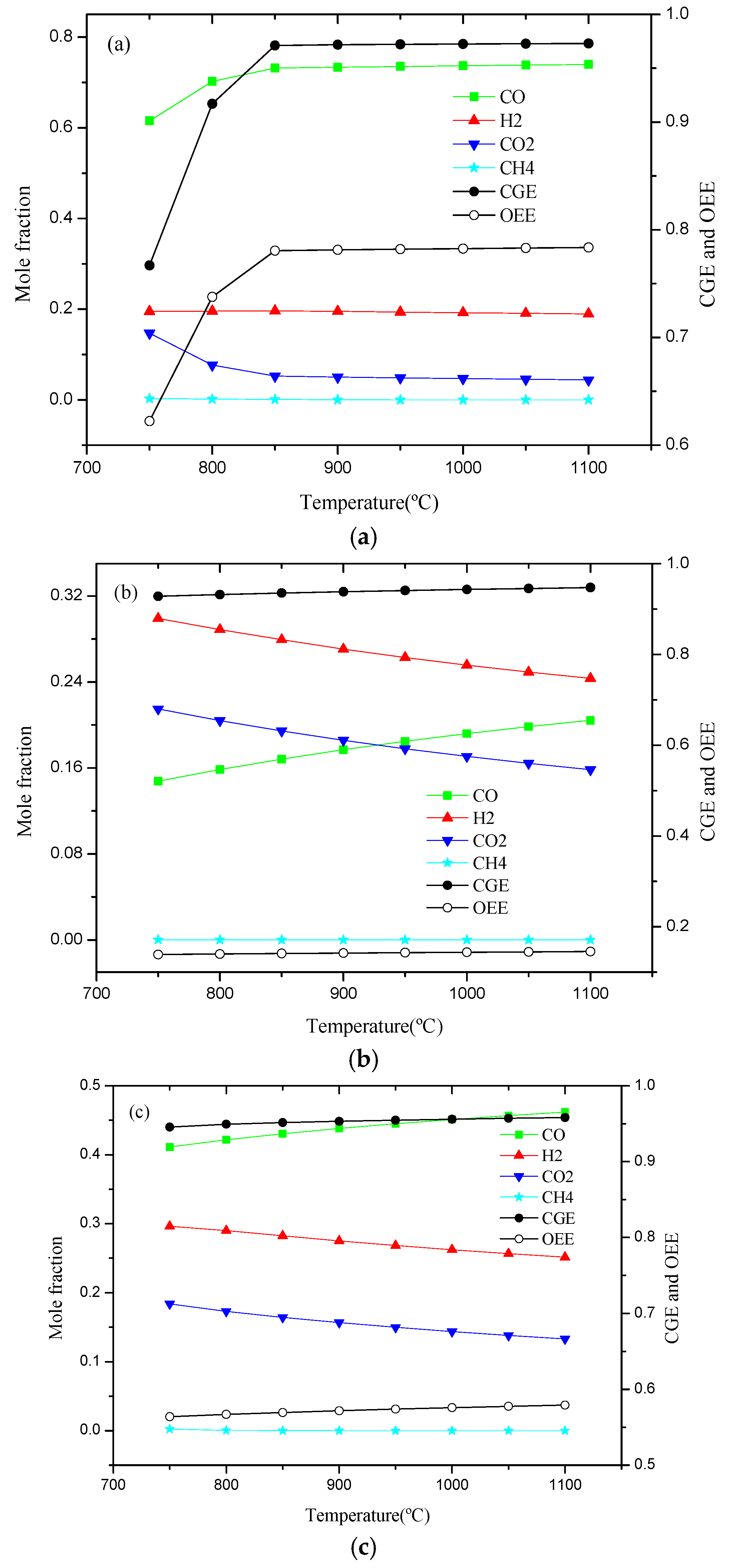
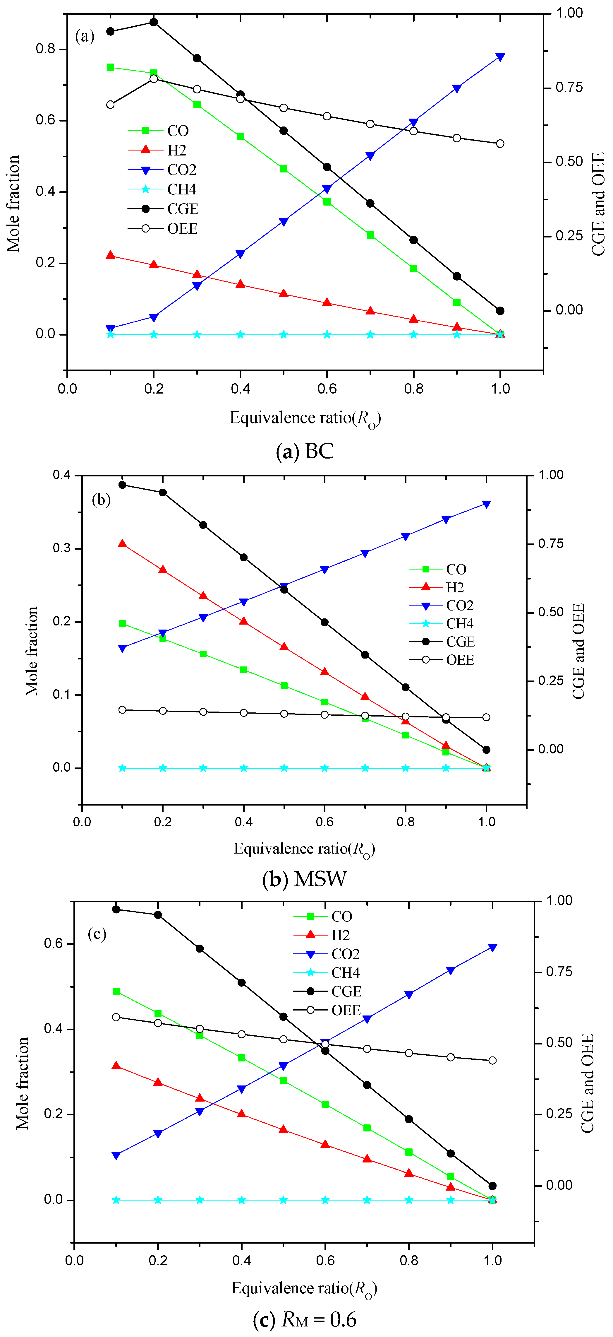
To better handle MSW and achieve resource recycling, an integrated CO2/O2 co-gasification system of MSW and BC with CO2 capture was developed and simulated by the Aspen plus. The established model in this work showed better reliability and accuracy. It was concluded that the gasification performance of BC was much different from that of MSW, and the addition of BC was beneficial to the gasification of MSW. Besides, the sensitivity analysis of the main operating parameters was investigated in detail. With increasing gasification temperature, the system exhibited better gasification performance, and 900 °C was a demarcation point of the reaction equilibrium at constant Ro and Rc. The oxygen equivalence ratio, Ro, had a sizable impact on the CGE and OEE of system, and indicated a relatively good performance when Ro was equal to 0.2. Moreover, the increase in the Rc ratio led to the decrease in H2 mole fraction due to the enhancement of reverse R9. With increasing MSW blends ratio, RM, the mole fraction of CO, CGE, and OEE of the system all decreased gradually. The relatively optimal operating conditions outlined by the analyses were set as T = 900 °C, Ro = 0.2, Rc = 0.5, and RM = 0.6. Using these operating conditions, it was possible to achieve the large processing capacity of MSW at the cost of efficiency; the corresponding OEE of system was 0.57.

Author Contributions

Conceptualization, G.D. and B.H.; methodology, G.D.; software, B.H.; validation, G.D. and B.H.; writing—review and editing, G.D. and B.H. All authors discussed the results. All authors have read and agreed to the published version of the manuscript.

Funding

This work is supported by the National Natural Science Foundation of China, Grant No. 51576014.

Conflicts of Interest

The authors declare no conflicts of interest.

Nomenclature

GGibbs free energy of system, kJ
MTotal number of phases
TGasification temperature, °C
Q1Heats required for MSW drying, kW
Q2Heats required for BC drying, kW
QLHeat loss of reaction system, kW
QCAHeat amount for CO2 absorption unit, kW
RoOxygen equivalence ratio
RcMole of CO2 to carbon ratio
RMMSW blending ratio
SNumber of single phase
WASUEnergy consumption for O2 production, kJ
ycCarbon content in the fed fuel
Abbreviations
ASUAir separation unit
BCBituminous coal
CGECold gas efficiency
HDCHigh distillation column
HHVHigher heating value
LDCLow distillation column
LHVLower heating value
MSAMolecular sieve adsorber
MSWMunicipal solid waste
OEEOverall energy efficiency

References

  1. National Bureau of Statistics of China. China Statistical Yearbook; China Statistics Press: Beijing, China, 2016. [Google Scholar]
  2. Ding, G.C.; He, B.S.; Yao, H.F.; Cao, Y.; Su, L.B.; Duan, Z.P. Co-combustion behaviors of municipal solid waste and low-rank coal semi-coke in air or oxygen/carbon dioxide atmospheres. J. Therm. Anal. Calorim. 2019. [Google Scholar] [CrossRef]
  3. Dong, Q.Z.; Tan, S.K.; Gersberg, R.M. Municipal solid waste management in China: Status, problems and challenges. J. Environ. Manag. 2010, 91, 1623–1633. [Google Scholar]
  4. Zhu, L.; Zhang, L.; Fan, J.M.; Jiang, P.; Li, L.L. MSW to synthetic natural gas: System modeling and thermodynamics assessment. Waste Manag. 2016, 48, 257–264. [Google Scholar] [CrossRef]
  5. Niu, M.M.; Huang, Y.J.; Jin, B.S.; Wang, X.Y. Oxygen gasification of municipal solid waste in a fixed-bed gasifier. Chin. J. Chem. Eng. 2014, 22, 1021–1026. [Google Scholar] [CrossRef]
  6. Luz, F.C.; Rocha, M.H.; Lora, E.E.S.; Venturini, O.J.; Andrade, R.V.; Leme, M.M.V.; Olmo, O.A.D. Techno-economic analysis of municipal solid waste gasification for electricity generation in Brazil. Energy Convers. Manag. 2015, 103, 321–337. [Google Scholar] [CrossRef]
  7. Emami-Taba, L.; Irfan, M.F.; Daud, W.M.A.W.; Chakrabarti, M.H. Fuel blending effects on the co-gasification of coal and biomass-A review. Biomass Bioenergy 2013, 57, 249–263. [Google Scholar] [CrossRef]
  8. Pinto, F.; Lopes, H.; Andre, R.N.; Gulyurtlu, I.; Cabrita, I. Effect of catalysts in the quality of syngas and by-products obtained by co-gasification of coal and wastes. 1. Tars and nitrogen compounds abatement. Fuel 2007, 86, 2052–2063. [Google Scholar] [CrossRef]
  9. Pinto, F.; Lopes, H.; Andre, R.N.; Gulyurtlu, I.; Cabrita, I. Effect of catalysts in the quality of syngas and by-products obtained by co-gasification of coal and wastes. 2: Heavy metals, sulphur and halogen compounds abatement. Fuel 2008, 87, 1050–1062. [Google Scholar] [CrossRef]
  10. Zaccariello, L.; Mastellone, M. Fluidized-bed gasification of plastic waste, wood, and their blends with coal. Energies 2015, 8, 8052–8068. [Google Scholar] [CrossRef] [Green Version]
  11. Pinto, F.; Andre, R.N.; Carolino, C.; Miranda, M. Hot treatment and upgrading of syngas obtained by co-gasification of coal and wastes. Fuel Process. Technol. 2014, 126, 19–29. [Google Scholar] [CrossRef] [Green Version]
  12. Ramos, A.; Monteiro, E.; Silva, V.; Rouboa, A. Co-gasification and recent developments on waste-to-energy conversion: A review. Renew. Sustain. Energy Rev. 2018, 81, 380–398. [Google Scholar] [CrossRef]
  13. Hu, B.H.; Huang, Q.X.; Buekens, A.; Chi, Y.; Yan, J.H. Co-gasification of municipal solid waste with high alkali coal char in a three-stage gasifier. Energy Convers. Manag. 2017, 153, 473–481. [Google Scholar] [CrossRef]
  14. Cormos, C.C. Techno-economic and environmental analysis of hydrogen and power co-generation based on co-gasification of coal and biomass/solid wastes with carbon capture. Chem. Eng. 2014, 37, 139–144. [Google Scholar]
  15. Soreanu, G.; Tomaszewicz, M.; Fernandez-Lopez, M.; Valverde, J.L.; Zuwala, J.; Sanchez-Silva, L. CO2 gasification process performance for energetic valorization of microalgae. Energy 2017, 119, 37–43. [Google Scholar] [CrossRef]
  16. Adnan, M.A.; Hossain, M.M. Gasification performance of various microalgae biomass-A thermodynamic study by considering tar formation using Aspen plus. Energy Convers. Manag. 2018, 165, 783–793. [Google Scholar] [CrossRef]
  17. Kuo, P.; Wu, W. Thermodynamic analysis of a combined heat and power system with CO2 utilization based on co-gasification of biomass and coal. Chem. Eng. Sci. 2016, 142, 201–214. [Google Scholar] [CrossRef]
  18. Adnan, M.A.; Hossain, M.M. Co-gasification of Indonesian coal and microalgae—A thermodynamic study and performance evaluation. Chem. Eng. Process. Process Intensif. 2018, 128, 1–9. [Google Scholar] [CrossRef]
  19. Wang, Z.W.; Burra, K.G.; Lei, T.Z.; Gupta, A.K. Co-gasification characteristics of waste tire and pine bark mixtures in CO2 atmosphere. Fuel 2019, 257, 116025. [Google Scholar] [CrossRef]
  20. Kan, X.; Chen, X.P.; Shen, Y.; Lapkin, A.A.; Kraft, M.; Wang, C.H. Box-Behnken design based CO2 co-gasification of horticultural waste and sewage sludge with addition of ash from waste as catalyst. Appl. Energy 2019, 242, 1549–1564. [Google Scholar] [CrossRef]
  21. Fan, J.M.; Hong, H.; Zhang, L.; Li, L.L.; Jin, H.G. Thermodynamic performance of SNG and power coproduction from MSW with recovery of chemical unreacted gas. Waste Manag. 2017, 67, 163–170. [Google Scholar] [CrossRef]
  22. Wang, S.; Zhang, X.; Chen, H.; Zhou, L. Modeling of air separation system based on cryogenic technique. J. North China Electr. Power Univ. 2006, 33, 64–66. [Google Scholar]
  23. Ding, G.C.; He, B.S.; Cao, Y.; Wang, C.J.; Su, L.B.; Duan, Z.P.; Song, J.G.; Tong, W.X.; Li, X.Z. Process simulation and optimization of municipal solid waste fired power plant with oxygen/carbon dioxide combustion for near zero carbon dioxide emission. Energy Convers. Manag. 2018, 157, 157–168. [Google Scholar] [CrossRef]
  24. Liang, C.; Zhang, H.X.; Zhu, Z.P.; Na, Y.J.; Lu, Q.G. CO2-O2 gasification of a bituminous in circulating fluidized bed. Fuel 2017, 200, 81–88. [Google Scholar] [CrossRef]
  25. Han, J.; Liang, Y.; Hu, J.; Qin, L.B.; Street, J.; Lu, Y.W.; Yu, F. Modeling downdraft biomass gasification process by restricting chemical reaction equilibrium with Aspen Plus. Energy Convers. Manag. 2017, 153, 641–648. [Google Scholar] [CrossRef]
  26. Dhanavath, K.N.; Shah, K.; Bhargava, S.K.; Bankupalli, S.; Parthasarathy, R. Oxygen–steam gasification of karanja press seed cake: Fixed bed experiments, ASPEN Plus process model development and benchmarking with saw dust, rice husk and sunflower husk. J. Environ. Chem. Eng. 2018, 6, 3061–3069. [Google Scholar] [CrossRef]
  27. Kuo, P.C.; Wu, W.; Chen, W.H. Gasification performances of raw and torrefied biomass in a downdraft fixed bed gasifier using thermodynamic analysis. Fuel 2014, 117, 1231–1241. [Google Scholar] [CrossRef]
  28. Gonzaleza, J.F.; Romana, S.; Bragadoa, D.; Calderonb, M. Investigation on the reactions influencing biomass air and air/steam gasification for hydrogen production. Fuel Process. Technol. 2008, 89, 764–772. [Google Scholar] [CrossRef]
  29. Fu, C.; Gundersen, T. Using exergy analysis to reduce power consumption in air separation units for oxy-combustion processes. Energy 2012, 44, 60–68. [Google Scholar] [CrossRef]
  30. Duan, W.J.; Yu, Q.B.; Wang, K.; Qin, Q.; Hou, L.M.; Yao, X.; Wu, T.W. ASPEN Plus simulation of coal integrated gasification combined blast furnace slag waste heat recovery system. Energy Convers. Manag. 2015, 100, 30–36. [Google Scholar] [CrossRef]
  31. Chen, C.; Jin, Y.Q.; Yan, J.H.; Chi, Y. Simulation of municipal solid waste gasification in two different types of fixed bed reactors. Fuel 2013, 103, 58–63. [Google Scholar] [CrossRef]
  32. Peters, L.; Hussain, A.; Follmann, M.; Melin, T.; Hagg, M.B. CO2 removal from natural gas by employing amine absorption and membrane technology-A technical and economical analysis. Chem. Eng. J. 2011, 172, 952–960. [Google Scholar] [CrossRef]
  33. Cao, Y.; He, B.S.; Ding, G.C.; Su, L.B.; Duan, Z.P. Energy and exergy investigation on two improved IGCC power plants with different CO2 capture schemes. Energy 2017, 140, 47–57. [Google Scholar] [CrossRef]
  34. Chaiwatanodom, P.; Vivanpatarakij, S.; Assabumrungrat, S. Thermodynamic analysis of biomass gasification with CO2 recycle for synthesis gas production. Appl. Energy 2014, 114, 10–17. [Google Scholar] [CrossRef]
  35. Jassim, M.S.; Rochelle, G.T. Innovative absorber/stripper configurations for CO2 capture by aqueous monoethanolamine. Ind. Eng. Chem. Res. 2006, 45, 2465–2474. [Google Scholar] [CrossRef]
  36. Gagliano, A.; Nocera, F.; Bruno, M.; Cardillo, G. Development of an equilibrium-based model of gasification of biomass by Aspen Plus. Energy Procedia 2017, 111, 1010–1019. [Google Scholar] [CrossRef]
  37. Xiao, X.B.; Wang, X.Y.; Zheng, Z.M.; Qin, W.; Zhou, Y. Catalytic coal gasification process simulation with alkaline organic wastewater in a fluidized bed reactor using Aspen Plus. Energies 2019, 12, 1367. [Google Scholar] [CrossRef] [Green Version]
  38. Villarini, M.; Marcantonio, V.; Colantoni, A.; Bocci, E. Sensitivity analysis of different parameters on the performance of a CHP internal combustion engine system fed by a biomass waste gasifier. Energies 2019, 12, 688. [Google Scholar] [CrossRef] [Green Version]
  39. Yan, L.B.; Wang, Z.Q.; Cao, Y.; He, B.S. Comparative evaluation of two biomass direct-fired power plants with carbon capture and sequestration. Renew. Energy 2020, 147, 1188–1198. [Google Scholar] [CrossRef]
  40. Ramzan, N.; Asma, A.; Naveed, S.; Malik, A. Simulation of hybrid biomass gasification using Aspen plus: A comparative performance analysis for food, municipal solid and poultry waste. Biomass Bioenergy 2011, 35, 3962–3969. [Google Scholar] [CrossRef]
  41. Karamarkovic, R.; Karamarkovic, V. Energy and exergy analysis of biomass gasification at different temperatures. Energy 2010, 35, 537–549. [Google Scholar] [CrossRef]
  42. Kraisornkachit, P.; Vivanpatarakij, S.; Amornraksa, S.; Simasatitkul, L.; Assabumrungrat, S. Performance evaluation of different combined systems of biochar gasifier, reformer and CO2 capture unit for synthesis gas production. Int. J. Hydrog. Energy 2016, 41, 13408–13418. [Google Scholar] [CrossRef]
  43. Renganathan, T.; Yadav, M.V.; Pushpavanam, S.; Voolapalli, R.K.; Cho, Y.S. CO2 utilization for gasification of carbonaceous feedstocks: A thermodynamic analysis. Chem. Eng. Sci. 2012, 83, 159–170. [Google Scholar] [CrossRef]
  44. Adnan, M.A.; Susanto, H.; Binous, H.; Muraza, O.; Hossain, M.M. Feed compositions and gasification potential of several biomasses including a microalgae: A thermodynamic modeling approach. Int. J. Hydrog. Energy 2017, 42, 17009–17019. [Google Scholar] [CrossRef]
  45. Wang, S.; Bi, X.; Wang, S. Thermodynamic analysis of biomass gasification for biomethane production. Energy 2015, 90, 1207–1218. [Google Scholar] [CrossRef]
  46. Li, K.; Zhang, R.; Bi, J. Experimental study on syngas production by co-gasification of coal and biomass in a fluidized bed. Int. J. Hydrog. Energy 2010, 35, 2722–2726. [Google Scholar] [CrossRef]
  47. Cheng, Y.P.; Thow, Z.H.; Wang, C.H. Biomass gasification with CO2 in a fluidized bed. Powder Technol. 2016, 296, 87–101. [Google Scholar] [CrossRef]
  48. Adnan, M.A.; Hossain, M.M. Gasification of various biomasses including microalgae using CO2—A thermodynamic study. Renew. Energy 2018, 119, 598–607. [Google Scholar] [CrossRef]
Figure 1. The schematic of the MSW/BC co-gasification system in CO2/O2 atmosphere.
Applsci 10 01921 g001
Figure 2. The detailed flowchart of the MSW/BC CO2/O2 co-gasification system with Aspen plus.
Applsci 10 01921 g002
Figure 3. Effect of gasification temperature T on raw syngas composition and system performance (Ro = 0.2 and Rc = 0.5). (a) BC; (b) MSW; (c) RM = 0.6
Applsci 10 01921 g003
Figure 4. Effect of Ro on raw syngas composition and system performance (T = 900 °C and Rc = 0.5): (a) BC; (b) MSW; (c) RM = 0.6.
Applsci 10 01921 g004
Figure 5. Effect of Rc on raw syngas composition and system performance (T = 900 °C and Ro = 0.2): (a) BC; (b) MSW; (c) RM = 0.6.
Applsci 10 01921 g005
Figure 6. Effect of RM on raw syngas composition and system performance (T = 900 °C; Ro = 0.2; and Rc = 0.5).
Applsci 10 01921 g006
Table 1. The proximate and the ultimate analyses of raw municipal solid waste (MSW) and bituminous coal.
SamplesUltimate Analyses (wt%)Proximate Analyses (wt%)
MSW [23]CdHdOdNdSdCldMarVdFCdAdHHV (MJ/kg)
34.624.8723.631.290.310.674857.777.6234.6114.687
BC [24]CadHadOadNadSadCladMadVadFCadAadLHV (MJ/kg)
71.864.1511.050.880.3606.932.7955.514.8027.68
Table 2. Chemical reactions in the co-gasification process of MSW and bituminous coal (BC) [25,26,27,28].
IDChemical ReactionReaction Heat (ΔH)Reaction Name
R1 MSW / coal Dried   MSW / coal + H 2 O --Drying
R2 Dried   MSW / coal Char + CO + H 2 + CO 2 + H 2 O + H 2 S + N 2 + CH 4 + Tar --Pyrolysis
R3 C + 0.5 O 2 CO −111 MJ/kmolPartial oxidation
R4 C + CO 2 2 CO +172 MJ/kmolBoudouard
R5 C + H 2 O CO + H 2 +131 MJ/kmolSteam reforming
R6 C + 2 H 2 CH 4 −74 MJ/kmolMethanation
R7 H 2 + 0.5 O 2 H 2 O −484 MJ/kmolH2 oxidation
R8 CO + 0.5 O 2 CO 2 −284 MJ/kmolCO combustion
R9 CO + H 2 O CO 2 + H 2 −41 MJ/kmolWater gas shift
R10 CH 4 + H 2 O CO + 3 H 2 +206 MJ/kmolMethane-steam reforming
R11 CH 4 + CO 2 2 CO + 2 H 2 +247 MJ/kmolMethane-CO2 reforming
Table 3. Comparison of the monoethanolamine (MEA) model simulation with reported data.
ParametersSimulatedChaiwatanodom [34]Jassim [35]
Energy consumption at 90% removal of CO2 (MJ/kg)3.03.02.38–4.51
Table 4. The operating parameters of co-gasification system of MSW and coal in CO2/O2 atmosphere.
ParametersDescription
ASU-
Oxygen content in oxidant95%
Temperature/Pressure25 °C/0.12 MPa
Power consumption0.324 kWh/Nm3
Co-gasification process-
Total fuel flow rate100 kg/h
MSW blending ratio (RM)0–1
Gasifier temperature/Pressure750–1100 °C/ 0.101MPa
Oxygen to carbon ratio (Ro)0.1–1
CO2 to carbon ratio (Rc)0.1–1
CO2 absorption unit-
CO2 capture efficiency90%
CO2 absorption energy consumption3 MJ/kg
Compressor isentropic efficiency0.85
Compressor mechanical efficiency0.95
Table 5. Comparison of the producer gas composition simulated by this model and literature values.
CompositionPresent WorkRenganathan [43]Adnan [18]Error1Error2
T = 800 °C
H230.21%30.70%30.45%−0.49%−0.24%
CO61.01%60.00%63.20%1.01%−2.19%
CO28.12%9.80%5.97%−1.68%2.15%
CH40.26%0.00%0.38%0.26%−0.12%
T = 1000 °C
H229.87%29.00%30.33%0.87%−0.46%
CO64.21%62.50%67.00%1.71%−2.79%
CO24.56%8.10%2.66%−3.54%1.90%
CH40.01%0.00%0.01%0.01%0.00%

