Article

Relationship between Buchholz’s Apparent Power and Instantaneous Power in Three-Phase Systems

by
Vicente León-Martínez
1,
Joaquín Montañana-Romeu
1,*,
Elisa Peñalvo-López
1 and
Iván Valencia-Salazar
2
1
Universitat Politècnica de València, Camino de Vera 14, 46022 València, Spain
2
Instituto Tecnológico de Veracruz, Miguel Ángel de Quevedo 2779, 91897 Veracruz, Mexico
*
Author to whom correspondence should be addressed.
Appl. Sci. 2020, 10(5), 1798; https://doi.org/10.3390/app10051798
Submission received: 9 January 2020 / Revised: 25 February 2020 / Accepted: 27 February 2020 / Published: 5 March 2020

Abstract

:
Similarly to how Steinmetz developed his theory of alternating current in single-phase sinusoidal systems, a few formal relationships between expressions of the instantaneous and Buchholz’s apparent power in three-phase systems were identified in this paper. Based on these relationships, a methodology to express Buchholz’s apparent power and its components in any three-phase, wye-configured system—sinusoidal or non-sinusoidal, balanced or unbalanced—through instantaneous power expressions was established. The application of the proposed method to the entire system allowed the determination of a novel quantity referred to as neutral-displacement power, which measured the impacts of the phenomena caused by the neutral path operation on the values of the source and load apparent power. These impacts were analyzed using a real-world urban installation with a neutral conductor deterioration simulation via an Excel platform as an application example.

1. Introduction

Apparent power is used to design generators and transformers in power systems and can be applied to electrical network line calculations, as well as the selection of the size of equipment, such as electronic converters and measurement instruments. In our opinion, apparent power should also measure the combined effects of all phenomena that manifest in power systems.
The above information exhibits the importance of apparent power in electrical grids. However, the definition of apparent power in three-phase systems is currently an open issue. Since Steinmetz [1] formulated apparent power in single-phase sinusoidal circuits in the late 19th century, many definitions of apparent power were proposed in single- and three-phase systems. Steinmetz’s apparent power is related to instantaneous power, and this relationship also extends to the apparent power components, namely, active and reactive power. Instantaneous power is the quantity (along with the active power) directly related to the energy, or the rate with which the energy is transferred in a circuit; hence, the relationship between the apparent and instantaneous power confer a certain physical meaning to the apparent power. For this reason, Budeanu [2] used instantaneous power to formulate apparent power and its components in single-phase non-sinusoidal systems. However, some of Budeanu’s apparent power components, such as the reactive and distortion power, did not achieve the unanimous consensus of the scientific community, as specified by Czarnecki [3]; thus, other approaches considered that a physical interpretation was not necessary and defined apparent power in regard to the voltage and current waveforms. Buchholz [4], for three-phase power systems, and Fryze [5], for non-sinusoidal single-phase power systems, pioneered these approaches, and their influence extended to researchers such as Czarnecki in the 1980s [6] and even until now [7,8].
In spite of the errors regarding Budeanu’s approach, the search for the physical meaning of apparent power was not abandoned and was recently studied in three-phase systems through different approaches, including the IEEE Standard 1459-2010 [9] and DIN 40110-2 [10]. The IEEE Standard 1459, which was based in part on research developed by Emanuel [11,12,13], and the DIN 40110-Teil 2, which was supported by Depenbrock [14] and Ferrero [15], were strongly influenced by the definitions of apparent power suggested by Lyon in 1920 [16] and by Curtis and Silsbee in 1935 [17], who established that, in single-phase systems, “Apparent power is numerically equal to the maximum active power that can exist at given points of entry with the given effective value of the sinusoidal current and potential difference and hence is directly related to the size of the required equipment and to the generating and transmitting losses”.
In our opinion, the relationships between apparent and instantaneous power established by Steinmetz can also be generalized to three-phase sinusoidal and non-sinusoidal, balanced and unbalanced power systems and can be extended to their components. These relationships are described in Section 2 in which several formal similarities between Buchholz’s apparent power and instantaneous power are identified in three-phase, four-wire power systems [18]. According to these similarities, an original procedure to obtain the expressions for Buchholz’s apparent power and a set of power components (i.e., fundamental, positive-sequence active and reactive power, as well as unbalanced and non-fundamental power) are described in Section 3 for three-phase, wye-configured systems. These types of power are expressed as functions of well-known voltage and current components that obey Kirchhoff’s laws, Fortescue’s theorem, and the Fourier series. This methodology can be applied to determine Buchholz’s apparent power and its components, not only for a part of the power system, but also for the entire system, thereby allowing new quantities to be obtained to measure phenomena in power systems which cannot be identified using other approaches. Thus, Section 4 describes the formulation of the power effects of the phenomena [19,20] manifested by the neutral conductor in three-phase, wye-configured systems as an application of our proposed methodology. This novel power, referred to as neutral-displacement power, is not the neutral apparent power already defined in the literature [19,20]; rather, it defines the amount of apparent power or impact at the sources and loads caused by neutral path operation (real or virtual) in power systems. The neutral-displacement power in three-phase, wye-configured systems depends on the zero-sequence fundamental and non-fundamental voltages at a source or load, but is independent of the neutral current. Therefore, our expression for neutral-displacement power can be applied to power systems with no neutral conductor. Section 5 analyzes a real three-phase four-wire urban installation according to the power expressions obtained from our proposed methodology in order to determine the effects of the deterioration of the neutral conductor using an Excel simulation. Finally, conclusions in Section 6 present our main contributions in this paper, namely
(1)
Verification that instantaneous and Buchholz’s apparent powers are formally related quantities, as only Steinmetz could demonstrate for single-phase sinusoidal systems, 120 years ago;
(2)
Proposal of an original methodology to fast and directly obtain the expressions of Buchholz’s apparent power and its components in any three-phase system, sinusoidal or non-sinusoidal, balanced or unbalanced, star- or delta-configured systems, although the procedure is applied only to star-configured systems in this paper;
(3)
The methodology has been applied to obtain a novel quantity that we referred to as neutral-displacement power, which is able to determine the effects of the neutral path (real or virtual) in three-phase power systems.

2. Formulations of Apparent and Instantaneous Power in Three-Phase Wye-Configured Systems

In this section, the expressions for Buchholz’s apparent power, the instantaneous power, and their respective components are established at the point of common coupling (PCC) of the source and load of a three-phase, unbalanced, non-sinusoidal power system using the source neutral point (N) as voltage reference, as demonstrated in Figure 1.

2.1. Instantaneous Power

Instantaneous power refers to the velocity of the energy delivery in a system, which is directly related to the energy and its components to identify power phenomena that manifest in the system. The instantaneous active power transferred under fundamental-frequency and positive-sequence voltages and currents is the only instantaneous power component delivered in efficient (ideal) power systems. The other instantaneous power components manifest due to the inefficiencies present in the system, such as reactance, imbalance, and distortion. Therefore, a power system is less efficient when the instantaneous power possesses more components.
The instantaneous power source in the system illustrated in Figure 1 can be expressed as follows:
p S ( t ) = z = A , B , C v z N · i z
where v z N is the source of instantaneous line-to-neutral voltages in each phase ( z = A , B , C ) of the point of common coupling (PCC) of the source and the load and i z is the line current (Figure 1).
The instantaneous line-to-neutral voltage sources and the line currents can be decomposed into fundamental-frequency ( v z N 1 ,   i z 1 ) and non-fundamental ( v z N H ,   i z H ) line-to-neutral voltages and line currents, respectively, using the Fourier series:
v z N = v z N 1 + v z N H = v z N 1 + x 1 v z N x   i z = i z 1 + i z H = i z 1 + y 1 i z y
If the source fundamental and non-fundamental line-to-neutral voltages and currents are used as determined by the Fourier series, the source instantaneous power can be expressed as follows:
p S ( t ) = z = A , B , C ( v z N 1 + v z N H ) · ( i z 1 + i z H ) = p S 1 ( t ) + p S H ( t )
where
p S 1 ( t ) = z = A , B , C v z N 1 · i z 1
is the source fundamental instantaneous power, and
p S H ( t ) = z = A , B , C ( v z N 1 · i z H + v z N H · i z ) = p S H I ( t ) + p S H V ( t )
is the source non-fundamental instantaneous power, which has two components, i.e., p S H I ( t ) , which represents the source instantaneous power caused exclusively by distorted currents, whereas p S H V ( t ) defines the source instantaneous power caused by distorted voltages.
The fundamental-frequency source line-to-neutral voltages and line currents can be expressed according to the following components in each phase ( z = A , B , C ) by applying Fortescue’s theorem:
v z N 1 = v z N 1 + + v z N 1 + v z N 1 0 = v z N 1 + + v z N 1 U i z 1 = i z 1 + + i z 1 + i z 1 0 = i z 1 + + i z 1 U
where v z N 1 +   and   i z 1 + are the fundamental-frequency positive-sequence source line-to-neutral voltages and line currents, respectively, and
v z N 1 U = v z N 1 + v z N 1 0 and i z 1 U = i z 1 + i z 1 0
are the source unbalanced line-to-neutral voltages and unbalanced line currents, respectively, which are formed by the fundamental-frequency negative- ( v z N 1 ,   i z 1 ) and zero-sequence ( v z N 1 0 ,   i z 1 0 ) components of the source line-to-neutral voltages and line currents.
Hence, the source fundamental-frequency instantaneous power (4) can also be expressed as a function of the symmetrical components of the voltages and currents resulting from Fortescue’s theorem, as defined in Equation (6). Thus, the following equation is obtained:
p S 1 ( t ) = z v z N 1 · i z 1 = z ( v z N 1 + + v z N 1 U ) · ( i z 1 + + i z 1 U ) = p S + ( t ) + p S U ( t )
where
p S + ( t ) = z v z N 1 + · i z 1 +
is the source fundamental-frequency positive-sequence instantaneous power, and
p S U ( t ) = z ( v z N 1 + · i z 1 U + v z N 1 U · i z 1 ) = p S U I ( t ) + p S U V ( t )
is the source unbalanced instantaneous power, which has two components, i.e., p S U I ( t ) , which represents the source instantaneous power due to current imbalances, and p S U V ( t ) , which represents the source instantaneous power caused by voltage imbalances.
Further, since the fundamental-frequency positive-sequence line currents can be expressed according to two components, namely, active ( i z 1 a + ) and reactive ( i z 1 r + ), the source fundamental-frequency positive-sequence instantaneous power (9) can generally be expressed as follows:
p S + ( t ) = z v z N 1 + · ( i z 1 a + + i z 1 r + ) = p S a + ( t ) + p S r + ( t )
according to two components, namely, active ( p S a + ( t ) ) and reactive ( p S r + ( t ) ).
The IEEE Standard 1459 [9] considers the above instantaneous power components to be of utmost interest. The active instantaneous power component ( p S a + ( t ) ) determines how electrical energy is transformed into light, heat, and mechanical energy in an ideal power system. The reactive instantaneous power component ( p S r + ( t ) ) “governs the fundamental voltage magnitude and its distribution along the feeders and affects electromechanical stability as well as the energy loss” [9].
Finally, according to Equations (3), (8), and (11), the source instantaneous power can generally be expressed according to the following main components:
p S ( t ) = p S a + ( t ) + p S r + ( t ) + p S U ( t ) + p S H ( t )

2.2. Buchholz’s Apparent Power

Buchholz defined apparent power in 1922 [4] as a function of RMS line-to-neutral voltages and line currents in three-phase, three-wire power systems, with no physical significance.
If we consider the neutral conductor to be a different subsystem to the source and load of the system illustrated in Figure 1, the source and load can be considered as a three-port subsystem to which Buchholz’s approach can be applied. Hence, the source apparent power can be expressed according to Buchholz’s approach as follows:
S S = z V z N 2 · z I z 2 = ( V A N 2 + V B N 2 + V C N 2 ) · ( I A 2 + I B 2 + I C 2 )
Using the Fourier series, the squares of the RMS values of these voltages and currents can be expressed as follows:
V z N 2 = V z N 1 2 + V z N H 2 = V z N 1 2 + x 1 V z N x 2   I z 2 = I z 1 2 + I z H 2 = I z 1 2 + y 1 I z y 2
where ( V z N 1   and   I z 1 ) denote the fundamental-frequency RMS values of each phase ( z = A , B , C ) of the source line-to-neutral voltages and line currents, respectively, and ( V z N H   and   I z H ) represent the RMS values of all harmonics without fundamental phase voltages and currents. Thus, the source apparent power can be expressed as follows:
S S = z ( V z N 1 2 + V z N H 2 ) · z ( I z 1 2 + I z H 2 ) = S S 1 2 + S S H 2
where S S 1 is the source fundamental-frequency apparent power,
S S 1 = z V z N 1 2 · z I z 1 2 = ( V A N 1 2 + V B N 1 2 + V C N 1 2 ) · ( I A 1 2 + I B 1 2 + I C 1 2 )
and S S H represents the source non-fundamental power,
S S H = z V z N 1 2 · z I z H 2 + z V z N H 2 · z I z 2 = ( S S H I ) 2 + ( S S H V ) 2
where
S S H I = z V z N 1 2 · z I z H 2 = ( V A N 1 2 + V B N 1 2 + V C N 1 2 ) · ( I A H 2 + I B H 2 + I C H 2 )
is the non-fundamental power corresponding to the distorted currents, exclusively, and
S S H V = z V z N H 2 · z I z 2 = ( V A H 2 + V B H 2 + V C H 2 ) · ( I A 2 + I B 2 + I C 2 )
is the non-fundamental power due to the distorted voltages.
On the other hand, the fundamental-frequency source line-to-neutral voltages and line currents of each phase ( z = A , B , C ) can be expressed as functions of their positive- (+), negative- (−), and zero-sequence (0) components, according to Fortescue’s theorem:
z V z N 1 2 = z [ ( V z N 1 + ) 2 + ( V z N 1 ) 2 + ( V z N 1 0 ) 2 ] = z [ ( V z N 1 + ) 2 + ( V z N 1 U ) 2 ] z I z 1 2 = z [ ( I z 1 + ) 2 + ( I z 1 ) 2 + ( I z 1 0 ) 2 ] = z [ ( I z 1 + ) 2 + ( I z 1 U ) 2 ]
Therefore, the source fundamental-frequency apparent power (16) can be decomposed into two components, similarly as expressed in reference [21], i.e.,
S S 1 = z [ ( V z N 1 + ) 2 + ( V z N 1 U ) 2 ]   · z [ ( I z 1 + ) 2 + ( I z 1 U ) 2 ] = S S + 2 + S S U 2
where S S + is the source fundamental-frequency positive-sequence apparent power,
S S + = [ ( V A N 1 + ) 2 + ( V B N 1 + ) 2 + ( V C N 1 + ) 2 ] · [ ( I A 1 + ) 2 + ( I B 1 + ) 2 + ( I C 1 + ) 2 ] = 3   V A N 1 + I A 1 +
and S S U is the source unbalanced power,
S S U = z ( V z N 1 + ) 2 · z ( I z 1 U ) 2 + z ( V z N 1 U ) 2 · z I z 1 2 = ( S S U I ) 2 + ( S S U V ) 2
where the source unbalanced power due to the current imbalances is represented by
S S U I = z ( V z N 1 + ) 2 · z ( I z 1 U ) 2 = V A N 1 + · 3 · [ ( I A 1 U ) 2 + ( I B 1 U ) 2 + ( I C 1 U ) 2 ] = = 3   V A N 1 + ( I A 1 ) 2 + ( I A 1 0 ) 2
where the superscripts and 0 denote the negative- and zero-sequence components of the fundamental-frequency line currents. The source unbalanced power determined by the voltage imbalance is represented by
S S U V = z ( V z N 1 U ) 2 · z I z 1 2 = [ ( V A N 1 U ) 2 + ( V B N 1 U ) 2 + ( V C N 1 U ) 2 ] · ( I A 1 2 + I B 1 2 + I C 1 2 ) = 3 · [ ( V A N 1 ) 2 + ( V A N 1 0 ) 2 ] · ( I A 1 2 + I B 1 2 + I C 1 2 )
The source fundamental-frequency positive-sequence apparent power (22) can be also expressed as
S S + = 3   V A N 1 + ( I A 1 a + ) 2 + ( I A 1 r + ) 2 = P S + 2 + Q S + 2
where
P S + = 3   V A N 1 + · I A 1 a +   and   Q S + = 3   V A N 1 + · I A 1 r +
represent the source fundamental-frequency positive-sequence active and reactive types of power, respectively.
Finally, the source apparent power can be formulated as a function of its components, as follows:
S S = P S + 2 + Q S + 2 + S S U 2 + S S H 2
The load apparent power and its components of the system in Figure 1 can be expressed similarly by using the values of the line currents and line-to-neutral voltages obtained by using the load neutral point ( n ) as a voltage reference.

2.3. Similarities between Formulations of Apparent Power and Instantaneous Power and their Components

Table 1 displays the expressions for instantaneous power and Buchholz’s apparent power and their respective components in a three-phase, non-sinusoidal, unbalanced subsystem.
A visual scan of these expressions reveals formal similarities between instantaneous and Buchholz’s apparent power, which are specified in the following principles:
(a)
The instantaneous power p ( t ) in each part or subsystem of a z-phase power system is defined by the inner products of the voltage ( v ) and current ( i ) vectors [22,23,24,25,26,27,28] formed by the instantaneous values of the voltages and currents in each phase of the subsystem ( p ( t ) = v · i ). Similarly, the instantaneous power components (active, reactive, unbalanced, non-fundamental, or distorted) are formed by the inner products of these voltage and current vector components.
(b)
The apparent power S in each part or subsystem of a z-phase power system is determined by the products of the norms (RMS values) of these voltage ( v ) and current ( i ) vectors in the subsystem ( S = | v | · | i | ). Moreover, the apparent power components represent products between the norms (RMS values) of the components (active, reactive, unbalanced, non-fundamental, or distorted) of the voltage and current vectors.
(c)
The instantaneous and apparent types of power have the same components, which contain terms formed by the same voltages and currents in these components. The instantaneous power components are arithmetically added and identify each power phenomenon present in any part of the system. In contrast, the squares of the apparent power components are added, as they are orthogonal quantities that quantify the effects of each phenomenon identified by the instantaneous power components.

3. Proposed Methodology to Obtain Formulations of Buchholz’s Apparent Power and a Possible Set of its Components

Based on the similarities between the instantaneous and Buchholz’s apparent power expressions, we developed a method to express Buchholz’s apparent power and one possible set of components derived from the instantaneous power in three steps. This method was applied to a three-phase system as follows.
(1)
The instantaneous power, p ( t ) , was expressed as a function of either of the following elements:
(1-a)
Its possible components (fundamental active ( + a ) and reactive ( + r ) of the positive-sequence, unbalanced ( U ), non-fundamental ( H ) system), i.e.,
p ( t ) = p + a + p + r + p U + p H
(1-b)
The instantaneous voltages and currents ( v z ,   i z ) in each phase ( z = A , B , C ), i.e.,
p ( t ) = v · i = ( v A v B v C ) · ( i A i B i C ) = z = A , B , C v z · i z
(1-c)
The instantaneous voltage and current components ( n v z n ,   m i z m ) in each phase ( z = A , B , C ), resulting in the application of Fortescue’s theorem and/or Fourier series to the part of the power system where the apparent power must be obtained, i.e.,
p ( t ) = v · i = ( n v A n n v B n n v C n ) · ( m i A m m i B m m i C m ) = z = A , B , C ( n v z n · m i z m )
(2)
The expressions were set for the square of the Buchholz’s apparent power using the following method:
(2-a)
If the instantaneous power was expressed according to (29), the square of the apparent power ( S 2 ) and the square of its possible components ( P + 2 ,   Q + 2 ,   S U 2 ,   S H 2 ) were expressed by applying the changes p ( t ) S 2 , p + a P + 2 , p + r Q + 2 , p U S U 2 , and p H S H 2 in order to obtain the general equation
S 2 = P + 2 + Q + 2 + S U 2 + S H 2
(2-b)
If the instantaneous power was expressed by (30), the square of the apparent power was expressed as the product of the squares of the norms of the voltage ( v ) and current ( i ) vectors, which were determined as the product of the squares of RMS voltages ( | v | 2 ) and currents ( | i | 2 ), i.e.,
S 2 = | v | 2 · | i | 2 = ( V A 2 + V B 2 + V C 2 ) · ( I A 2 + I B 2 + I C 2 ) = ( z V z 2 ) · ( z I z 2 )
where the vertical bars ( |   | ) represent the norm of a voltage or current vector;
(2-c)
If the instantaneous power was expressed according to (31) as a function of the components ( n , m ) of the voltage and current vectors in each phase ( z = A , B , C ), the square of the apparent power was expressed as the products of the squares of the RMS voltages and currents, which were obtained as functions of the RMS voltage components ( V z n ) and RMS current components ( I z m ) in each phase ( z = A , B , C ), as follows:
S 2 = ( n ( V A n 2 + V B n 2 + V C n 2 ) ) · ( m ( I A m 2 + I B m 2 + V C n 2 ) ) = ( z n V z n 2 ) · ( z m I z m 2 )
(3)
A square root was applied to Expressions (32), (33), and (34) to formulate the apparent power or its components.
The apparent power expressions derived from this methodology always agreed with Buchholz’s apparent power [4].

4. Formulation of the Neutral Conductor Effects According to the Proposed Methodology

The method described in Section 3 was useful to obtain the expressions for the apparent power and its components in the sources and loads of power systems. These expressions are summarized in Table 1. However, a relevant application of the proposed methodology is the establishment of expressions to measure the power effects caused by neutral conductor operation, which can be expressed by the neutral-displacement power ( S N ).
In this section, our proposed neutral-displacement power is expressed using the methodology described in Section 3 and the Conservation of Energy Principle in regard to the entire three-phase power system represented in Figure 1. In order to obtain accurate expressions for this power, it was necessary to consider the neutral conductor to be a different subsystem from the sources and loads (Figure 1).
When the neutral conductor impedance is not negligible or the neutral conductor does not exist, the source and load instantaneous power in the system of Figure 1 generally do not have the same values; the same occurs with the source and load apparent types of power, even if the subsystems are directly connected. These differences are caused by the phenomena that manifest via the operation of the neutral conductor and are identified by instantaneous power ( p N ( t ) ) in order to satisfy the Conservation of Energy Principle in the system presented in Figure 1.
As the loads are usually more unbalanced and distorted than the sources, the power effects that manifest via the neutral conductor (or neutral path) should be obtained as the differences between the load and source instantaneous types of power in order to satisfy the Conservation of Energy Principle throughout the entire power system. Hence, the neutral displacement instantaneous power can be expressed as follows:
p N ( t ) = p L ( t ) p S ( t ) = z = A , B , C ( v z n v z N ) · i z
This quantity identifies the phenomena associated with the operation of the neutral conductor.
One possible expression for the neutral displacement power can be identified by applying steps (2-a), (2-b), and (3) of the methodology established in Section 3 to Equation (35), as follows:
S N = S L 2 S S 2 = [ ( V A n 2 + V B n 2 + V C n 2 ) ( V A N 2 + V B N 2 + V C N 2 ) ] · ( I A 2 + I B 2 + I C 2 )
This power measures the effects of the neutral conductor operation and shows apparent power dimensions as it is defined as the quadratic difference between the apparent power of the load ( S L ) and source ( S S ). Equation (36) shows that the neutral-displacement power ( S N ) is not the neutral apparent power determined by the product of the RMS values of the neutral voltage drop and the neutral current ( V n N · I N ). Further, the neutral-displacement power is more suitable than the neutral apparent power ( V n N · I N ) for measuring the effects of the neutral conductor due to the following points:
(1)
In Expression (36), not only the active and reactive power in the neutral conductor are included, but also the power due to imbalances and distortions in the loads and sources;
(2)
The neutral-displacement power does not directly depend on the value of the neutral current ( I N ) and can also be applied to three-phase systems with no neutral conductor.
Other expressions of the neutral-displacement power can be obtained by considering the load and source line-to-neutral instantaneous voltages ( v z n ,   v z N ,   z = A , B , C ) as functions of all of their respective components:
v z n = v z n 1 + + v z n 1 + v z n 1 0 + h 1 v z n h   and   v z N = v z N 1 + + v z N 1 + v z N 1 0 + x 1 v z N x
As the positive- and negative-sequence components of the line-to-neutral voltages of directly connected loads and sources present the same values for each frequency, the neutral displacement instantaneous power (35) can be expressed according to Fortescue’s theorem as follows:
p N ( t ) = z = A , B , C [ ( v z n 1 0 v z N 1 0 ) + h = x h , x 1 ( v z n h 0 v z n x 0 ) ] · i z = p N L ( t ) p N S ( t )
where the superscript 0 denotes the zero-sequence components of these voltages, and p N L ( t ) and p N S ( t ) represent the neutral-displacement instantaneous power in the load and source, respectively.
The neutral displacement power is expressed by applying steps (2-a), (2-c), and (3) of the methodology described in Section 3 to Equation (38), as follows:
S N = 3 · [ ( ( V A n 1 0 ) 2 ( V A N 1 0 ) 2 ) + h = x h , x 1 ( ( V A n h 0 ) 2 ( V z n x 0 ) 2 ) ] · ( I A 2 + I B 2 + I C 2 ) = S N L 2 S N S 2
where the neutral displacement power caused by the load imbalances and distortions is
S N L = 3 · ( ( V A n 1 0 ) 2 + h 1 ( V A n h 0 ) 2 ) · ( I A 2 + I B 2 + I C 2 )
and the neutral displacement power due to the source imbalances and distortions is
S N S = 3 · ( ( V A N 1 0 ) 2 + x 1 ( V A N x 0 ) 2 ) · ( I A 2 + I B 2 + I C 2 )
According to our experiences with a great number of low-voltage industrial, commercial, and residential installations, the values of S N L and S N S are usually similar in terms of the neutral conductor’s rated conditions. However, when the neutral conductor impedance increases due to deterioration or other accidental faults, S N L strongly increases but S N S initially remains constant and finally slowly decreases down to zero, as demonstrated in the application example.

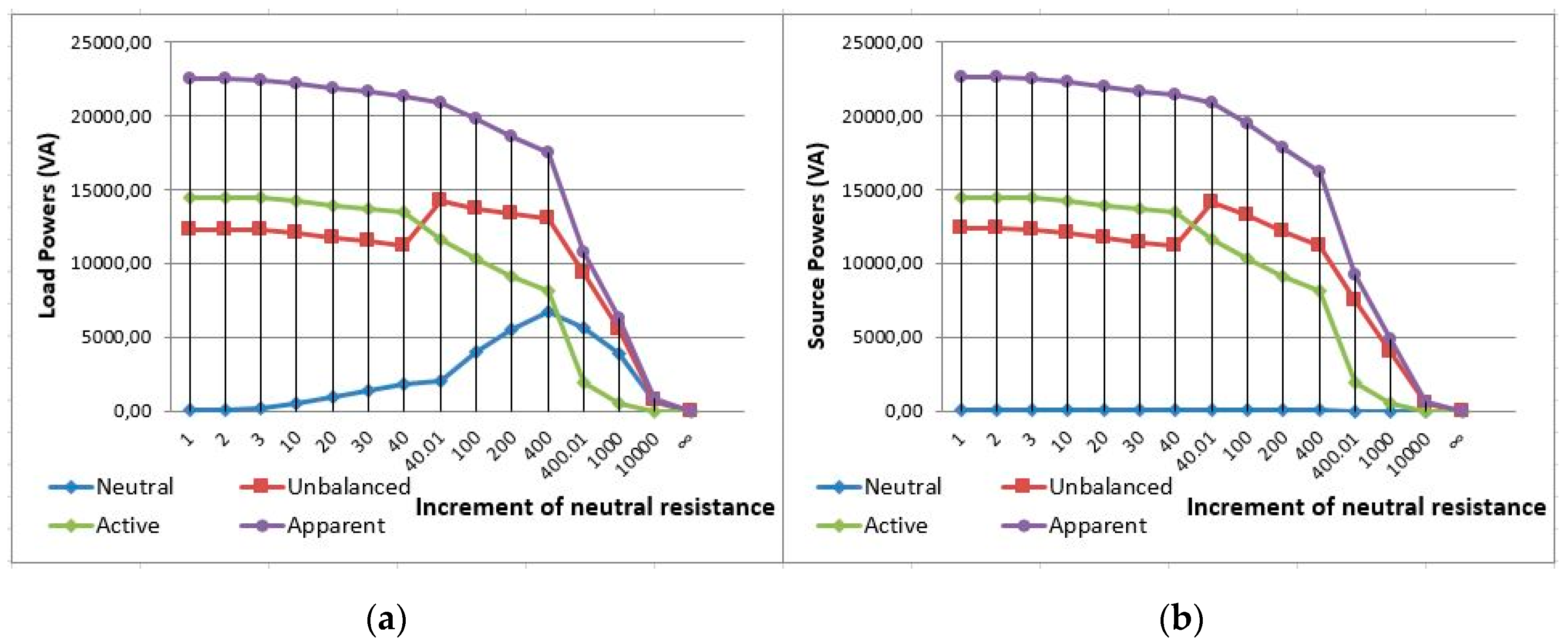
5. Application Example

A three-phase, four-wire, real-world, urban facility (Figure 2a) is analyzed in this section in regard to neutral conductor deterioration. This facility was supplied by a 400 kVA, 20 kV/395 V, Dyn11, three-phase transformer through three lines with a cross-sectional area of 16 mm2 and a length of 12.5 m (resistance of 0.0148 Ω) up to the PCC with the load in phases A and C, and a cross-sectional area of 10 mm2 and a length of 111 m (resistance of 0.21 Ω) in phase B. The neutral conductor resistance was 0.0148 Ω. The transformer short-circuit complex impedances were 0.0156 ∠74.57° (Ω) at the fundamental-frequency (50 Hz). The loads were houses and shops of a little village. The installation was strongly unbalanced, as shown from the active and reactive power registered by our SIMPELEC analyzer (Figure 2b), and slightly distorted (Figure 2c).
As the neutral conductor disrepair can be dangerous for loads, the effects of the neutral conductor deterioration were analyzed using an Excel simulation.
The evolution of the line-to-neutral voltages and active power in the load phases as a function of the increase of the neutral conductor resistance are represented in Figure 3, respectively. When the neutral conductor deteriorated, the voltage and active power of the least loaded phase (phase C) increased, whereas a decrease in voltage was observed for the other two phases, engendering a decrease in active power. When the resistance of the neutral conductor increased by a deterioration of up to approximately 40 times its rated value, the voltages in phase C were greater than 240 V, thereby causing the phase C loads to be disconnected by the protection device or become out of order. The active power in phase C became zero (Figure 3b) and the installation was more unbalanced. Therefore, phase B was the least loaded in these new conditions and the voltages and active power increased in this phase until the neutral conductor resistance reached 400 times its rated value (Figure 3). This engendered the disconnection of the phase B loads; only the phase A loads were supplied, reducing the voltages and active power in that phase according to the increase in neutral conductor resistance (Figure 3).
The load and source apparent power were reduced during neutral conductor deterioration (Figure 4); the same phenomenon occurred in regard to the total active power in the system, even when the active power in a phase of the load individually increased. The load and source unbalanced power increased when the phase C loads were disconnected. However, the reduction in the apparent and unbalanced power was less important in the loads than in the sources because of the strong increase in the load neutral displacement power (Figure 4a) compared to the negligible effects of the neutral conductor deterioration at the source (Figure 4b).
The minor effects engendered by the neutral conductor deterioration on the source are shown in Figure 5a in which a fast increase in the neutral-displacement power in the load is observed alongside a minor decrease in the source, even with remarkable neutral conductor deterioration. This result occurred in all of the power systems, independent of the power consumption and topology of the load or the value of the neutral resistance.
Further, the fast increase in the load neutral-displacement power is shown in Figure 5a. In fact, when the neutral conductor resistance presented a 10-fold increase, the increase in the load neutral-displacement power was six times larger (from 85.5 VA up to 510.2 VA), suggesting that the increment of the neutral-displacement power measured in the load was a more suitable parameter than the load overvoltage to detect fast neutral-wire deterioration [29]. The phase C line-to-neutral voltages only increased to 4.63 V (2%) during neutral conductor disrepair (Figure 5b), which was undetectable for most of the overvoltage protection relays.

6. Conclusions

A general procedure to obtain Buchholz’s apparent power expressions and their components in any power system was established in three-phase, wye-configured, non-sinusoidal, unbalanced power systems. The proposed methodology was based on the formal relationships between the instantaneous and apparent power expressions identified in these systems.
The proposed method can be applied either to an entire system or part of one. When the methodology was used in a part or subsystem of a power system, the expressions for the apparent power and its components obtained according to our proposed procedure in three-phase systems always led to Buchholz’s apparent power expression. When the proposed method was applied to the whole system, novel quantities to analyze power system operations were defined after the application of the proposed procedure, including the neutral-displacement power. This quantity expressed the amount of apparent power in sources and loads caused by the operation of the neutral path (real or virtual) in three-phase, non-sinusoidal, unbalanced systems. The neutral-displacement power was necessary to satisfy the Conservation of Energy Principle throughout the entire system and to explain the origin of the different values of the apparent power of directly connected sources and loads. The proposed neutral-displacement power was not the well-known neutral apparent power, which was defined by the active and reactive power in the neutral conductor, since this novel power included the source and load imbalance and distortion effects. The expression of the neutral-displacement power was consistent in the three-phase, wye-configured systems with no neutral conductor, as this power directly depended on the zero-sequence voltages in sources and loads and the line currents but not on the neutral current.
The proposed neutral displacement power was measured separately in sources and loads. The neutral-displacement power measured in the load strongly increased with increasing neutral conductor resistance, therefore, the increment of the load neutral-displacement power could be used as a suitable parameter to detect neutral conductor deterioration. However, the source neutral-displacement power was not able to detect neutral conductor malfunctions as its values were usually negligible and constant during neutral conductor deterioration.

7. Patents

The neutral displacement power ( S N ) established in Section 4 according to the proposed methodology described in Section 3 and, specifically, its load component ( S N L ) was used in the Spanish-granted patent ES 2588260 B2 described in reference [29].

Author Contributions

Conceptualization, V.L.-M., J.M.-R., and E.P.-L.; methodology, V.L.-M.; software, J.M.-R.; validation, V.L.-M., J.M.-R., and E.P.-L.; resources, V.L.-M., J.M.-R., and E.P.-L.; data curation, V.L.-M., J.M.-L., and E.P.-L.; writing—original draft preparation, V.L.-M.; writing—review and editing, J.M.-R., E.P.-L., and I.V.-S.; supervision, V.L.-M.; project administration, E.P.-L. and I.V.-S.; funding acquisition, E.P.-L. All authors read and agreed to the published version of the manuscript.

Funding

This research was funded by the European Commission, grant number 847132. The APC was funded by the European Commission, grant number 847132.

Acknowledgments

We gratefully thank Eléctrica de Vinalesa, S.L.U., for allowing us to take measurements using their electrical networks, and MDPI (www.mdpi.com/authors/english) for their English language editing. The authors deeply thank the European Commission for their support and funding provision.

Conflicts of Interest

The authors declare no conflict of interest.

References

  1. Steinmetz, C.P. Theory of Alternating Current Phenomena; McGraw: New York, NY, USA, 1897; pp. 150–157. [Google Scholar]
  2. Budeanu, I. Reactive and Fictitious Powers; The Rumanian National Institute Publ.: Bucharest, Romania, 1927. [Google Scholar]
  3. Czarnecki, L.S. What is wrong in the Budeanu concept of reactive and distortion power and why it should be abandoned. IEEE Trans. Instr. Meas. 1987, 36, 834–837. [Google Scholar] [CrossRef]
  4. Buchholz, F. Die Drehstrom-Scheinleistung bei Ungleichmas-siger Belastung Der Drei Zweige. Licht Und Kraft 1922, 2, 9–11. [Google Scholar]
  5. Fryze, S. Wirk, Blind, und Scheinleistung in elektrischen Stromkreisen mit nichtsinus-formigen Verlauf von Strom und Spannung. Elektrotechi 1932, 25, 596–599. [Google Scholar]
  6. Czarnecki, L.S. Orthogonal decomposition of the currents in a 3-phase non-linear asymmetrical circuit with non-sinusoidal voltage source. IEEE Trans. Instr. Meas. 1988, 37, 30–34. [Google Scholar] [CrossRef]
  7. Czarnecki, L.S. Currents physical components (CPC) concept: A fundamental of power theory. Prezglad Elektrotech. 2008, 6, 28–37. [Google Scholar] [CrossRef]
  8. Czarnecki, L.S.; Bhattarai, P. Currents physical components (CPC) in three-phase systems with asymmetrical voltage. Prezglad Elektrotech. 2015, 6, 40–47. [Google Scholar] [CrossRef]
  9. IEEE Standard 1459–2010. IEEE Trial-Use Standard for the Measurement of Electric Power Quantities under Sinusoidal, Non-sinusoidal, Balanced or Undalanced Conditions; The Institute of Electrical and Electronics Engineers Inc.: New York, NY, USA, 2010; pp. 1016–5997. [Google Scholar]
  10. DIN 40110, Teil 2. Mehrleiter-Strmkreise; Beuth-Verlag: Berlin, Germany, 2002. [Google Scholar]
  11. Emanuel, A.E. Apparent power definitions for three-phase systems. IEEE Trans. Power Deliv. 1999, 14, 767–772. [Google Scholar] [CrossRef]
  12. Pajic, S.; Emanuel, A.E. Modern apparent power definitions: Theoretical versus practical approach. The general case. IEEE Trans. PWD 2006, 21, 1787–1792. [Google Scholar] [CrossRef]
  13. Emanuel, A.E. Power Definitions and the Physical Mechanism of Power Flow; John Wiley & Sons: Chichester, UK, 2010. [Google Scholar]
  14. Depenbrock, M. The FBD-Method, a generally applicable tool for analyzing power relations. IEEE Trans. PWS 1993, 8, 381–387. [Google Scholar] [CrossRef]
  15. Ferrero, A. Definition of electrical quantities commonly used in non-sinusoidal conditions. ETEP Eur. Trans. PW Eng. 1998, 8, 235–240. [Google Scholar] [CrossRef]
  16. Lyon, W. Discussion on report of joint committee. Trans. AIEE 1920, 39, 1515–1520. [Google Scholar]
  17. Curtis, H.L.; Silsbee, F.B. Definitions of Power and Related Quantities. Electr. Eng. 1935, 4, 394–404. [Google Scholar] [CrossRef]
  18. León-Martínez, V.; Giner-García, J.; Montañana-Romeu, J.; Cazorla-Navarro, A. Efficiency in electrical installations. New power definitions (in Spanish). Mundo Electron. 2001, 332, 28–32. [Google Scholar]
  19. Emanuel, A.E.; Orr, J.A. The effect of the neutral path impedance on voltage and current distortion. Part I: Symmetrical and balanced three-phase systems. In Proceedings of the 2004 11th International Conference on Harmonics and Quality Power, Lake Placid, NY, USA, 12–15 September 2004; pp. 186–190. [Google Scholar] [CrossRef]
  20. Emanuel, A.E.; Orr, J.A. The effect of the neutral path impedance on voltage and current distortion. Part II: Imbalanced three-phase systems. In Proceedings of the 2004 11th International Conference on Harmonics and Quality Power, Lake Placid, NY, USA, 12–15 September 2004; pp. 186–190. [Google Scholar] [CrossRef]
  21. PBlasco, A.; Montoya-Mira, R.; Díez, J.M.; Montoya, R.; Reig, M.J. Compensation of Reactive Power and Unbalanced Power in Three-Phase Three-Wire Systems Connected to an Infinite Power Network. Appl. Sci. 2020, 10, 113. [Google Scholar] [CrossRef] [Green Version]
  22. Akagi, H.; Kanazawa, Y.; Nabae, A. Instantaneous reactive power compensators comprising switching devices without energy storage components. IEEE Trans. Ind. Appl. 1984, 20, 625–630. [Google Scholar] [CrossRef]
  23. Willems, J.L.; Ghijselen, J.A. The Relation between the Generalized Apparent Power and the Voltage Reference. In Proceedings of the Sixth International Workshop on Power Definitions and Measurements under Non-sinusoidal Conditions, Milano, Italy, 13–15 October 2003; pp. 37–45. [Google Scholar]
  24. Czarnecki, L.S. Could Power Properties of Three-Phase Systems Be Described in Terms of the Poynting Vector? IEEE Trans. Power Deliv. 2006, 21, 339–344. [Google Scholar] [CrossRef]
  25. Czarnecki, L.S. Physical Interpretation of the Reactive Power in Terms of the CPC Power Theory. Electr. Power Qual. Util. J. 2007, XIII, 89–95. [Google Scholar]
  26. Jeon, S.-J. Properties of the generalized power theory: Universality and portioning/augmentation properties. IET Gener. Transm. Distrib. 2015, 9, 2126–2134. [Google Scholar] [CrossRef]
  27. Czarnecki, L.S. Critical comments on the conservative power theory (CPT). In Proceedings of the 2015 International School on Nonsinusoidal Currents and Compensation (ISNCC), Lagow, Poland, 5–18 June 2015; pp. 1–7. [Google Scholar] [CrossRef]
  28. Artemenko, M.Y.; Batrak, L.M. The New Formula for Apparent Power and Power Losses of Three-Phase Four-Wire System. In Proceedings of the 2017 IEEE 37th International Conference on Electronics and Nanotechnology (ELNANO), Kyiv, Ukraine, 18–20 April 2017; pp. 389–393. [Google Scholar] [CrossRef]
  29. León-Martínez, V.; Montañana-Romeu, J. Procedure for Determining the Condition of the Neutral Conductor in Electrical Installations and the Procedure for Implementation Thereof. Spanish Granted Patent ES 2588260 B2, 9 May 2017. [Google Scholar]
Figure 1. Three-phase, four-wire, unbalanced, non-sinusoidal power system. (The head of the arrow voltages indicates the point of greatest potential).
Applsci 10 01798 g001
Figure 2. Real-world urban installation: (a) schematic representation; (b) active and reactive power; (c) main screen of the SIMPELEC nalyser representing the waves and harmonics of line currents.
Applsci 10 01798 g002
Figure 3. Voltages and powers in the load phases: (a) active power; (b) line-to-neutral voltages.
Applsci 10 01798 g003
Figure 4. Installation power: (a) load; (b) source.
Applsci 10 01798 g004
Figure 5. (a) Load and source neutral-displacement powers; (b) load phase voltages.
Applsci 10 01798 g005
Table 1. Summary of the instantaneous and apparent power expressions and their components in three-phase sources and loads according to our proposed approach.
ComponentsInstantaneous PowerApparent Power
Total p ( t ) = p a + ( t ) + p r + ( t ) + p U ( t ) + p H ( t ) S = P + 2 + Q + 2 + S U 2 + S H 2
p ( t ) = z = A , B , C v z · i z S = z V z 2 · z I z 2
FundamentalTotal p 1 ( t ) = z = A , B , C v z 1 · i z 1 S = z V z 1 2 · z I z 1 2
Active p a + ( t ) = z = A , B , C v z 1 + · i z 1 a + P + = 3   V A 1 + · I A 1 a +
Reactive p r + ( t ) = z = A , B , C v z 1 + · i z 1 r + Q + = 3   V A 1 + · I A 1 r +
UnbalancedTotal p U ( t ) = p U I ( t ) + p U V ( t ) S s U = ( S U I ) 2 + ( S U V ) 2
Current imbalance p U I ( t ) = z = A , B , C v z 1 + · i z 1 U S U I = z ( V z 1 + ) 2 · z ( I z 1 U ) 2
Voltage imbalance p U V ( t ) = z = A , B , C v z 1 U · i z 1 S U V = z ( V z 1 U ) 2 · z I z 1 2
Non-FundamentalTotal p H ( t ) = p H I ( t ) + p H V ( t ) S H = ( S H I ) 2 + ( S H V ) 2
Current distortion p H I ( t ) = z = A , B , C v z 1 · i z H S H I = z V z 1 2 · z I z H 2
Voltage distortion p H V ( t ) = z = A , B , C v z H · i z S H V = z V z H 2 · z I z 2

