Article

Wave Propagation in Periodic Metallic Structures with Equilateral Triangular Holes

by
Antonio Alex-Amor
1,2,*,
Guido Valerio
3,4,
Fatemeh Ghasemifard
5,
Francisco Mesa
6,
Pablo Padilla
2,
José M. Fernández-González
1 and
Oscar Quevedo-Teruel
5
1
Information Processing and Telecommunications Center, Universidad Politécnica de Madrid, 28040 Madrid, Spain
2
Departamento de Teoría de la Señal, Telemática y Comunicaciones, Universidad de Granada, 18071 Granada, Spain
3
Sorbonne Université, CNRS, Laboratoire de Génie Electrique et Electronique de Paris, 75252 Paris, France
4
Université Paris-Saclay, CentraleSupélec, CNRS, Laboratoire de Génie Electrique et Electronique de Paris, 91192 Gif-sur-Yvette, France
5
Division for Electromagnetic Engineering, School of Electrical Engineering and Computer Science, KTH Royal Institute of Technology, SE-100 44 Stockholm, Sweden
6
Microwaves Group, Department of Applied Physics 1, Escuela Técnica Superior de Ingenieria Informatica, Universidad de Sevilla, 41012 Sevilla, Spain
*
Author to whom correspondence should be addressed.
Appl. Sci. 2020, 10(5), 1600; https://doi.org/10.3390/app10051600
Submission received: 30 December 2019 / Revised: 22 January 2020 / Accepted: 18 February 2020 / Published: 28 February 2020
(This article belongs to the Special Issue Advanced Active and Passive Metasurfaces)

Abstract

:
This paper studies wave propagation in a periodic parallel-plate waveguide with equilateral triangular holes. A mode-matching method is implemented to analyze the dispersion diagram of the structure possessing glide and mirror symmetries. Both structures present an unexpected high degree of isotropy, despite the triangle not being symmetric with respect to rotations of 90°. We give some physical insight on the matter by carrying out a modal decomposition of the total field on the hole and identifying the most significant modes. Additionally, we demonstrate that the electrical size of the triangular hole plays a fundamental role in the physical mechanism that causes that isotropic behavior. Finally, we characterize the influence of the different geometrical parameters that conform the unit cell (period, triangle size, hole depth, separation between metallic plates). The glide-symmetric configuration offers higher equivalent refractive indexes and widens the stopband compared to the mirror-symmetric configuration. We show that the stopband is wider as the triangle size is bigger, unlike holey structures composed of circular and elliptical holes where an optimal hole size exists.

1. Introduction

Holey metasurfaces are obtained by etching small holes on a metallic plate in a periodic or locally periodic arrangement [1]. The simplicity of the fabrication process together with the advantageous wave-propagation properties obtained has boosted the interest in this class of structures. In fact, a single metallic sheet etched with holes can support plasmon-like waves (the so-called spoof-plasmons) even in the absence of dielectric or losses [2], in close similarity to the propagation in corrugated surfaces [3,4]. This phenomenon can be explained by considering that the presence of the periodic texture of holes gives rise to an equivalent impedance of the surface that actually allows for the propagation of bounded waves [3,4]. An alternative explanation in terms of equivalent plasma-like dielectric has also been presented [2]. The absence of material substrates in these fully metallic structures is quite beneficial because of the consequent reduction of losses. It leads to potential applications in microwave and photonics technology, not only for circuit devices [5] but also for antenna applications where the bounded waves are converted to leaky waves, responsible for highly directive radiation features [6].
In a first stage, only a single surface was considered in the analysis of holey metasurfaces, with no close scatterers interacting with that surface. However, in the last few years, a number of works have shown that a second metasurface, placed in the proximity of the first one and parallel to it, can drastically change the propagation properties of the complete structure. The wavenumber and the phase velocity of the resulting guided modes heavily depend on the mutual transverse shift between the metasurfaces. Interesting configurations are the mirror- and the glide-symmetric ones. In the former, the metasurfaces are simply mirrored one into the other one while, in the latter, they are off-shifted by half a period along the periodicity directions (see Figure 1). In this last configuration, modes propagating between the surfaces are low-dispersive over a large frequency band [7,8]. Furthermore, their stopbands benefit of stronger field attenuation and of a larger bandwidth with respect to the mirror-symmetric configuration [9,10]. Finally, glide-symmetric unit cells are able to produce higher levels of anisotropy [11], and higher magnetic responses [12].
In passband operation, the modal phase constant (and then the equivalent refractive index of the mode) can easily be tuned by varying the geometry of the periodic lattice, leading to the design of miniaturized structures [13,14] and synthesis of low-loss ultra-wideband graded-index lenses. For example, Luneburg lenses have been reported to provide beam scanning in a wide angular region without pattern deterioration [7,11,15]. In stopband operation, these surfaces can efficiently isolate microwave circuits and enhance the performance of gap waveguides [16,17,18,19,20]. Apart from the previous control on the the behaviour of holey structures by acting on the geometric parameters of the holes and the lattice, it has also been shown that different shapes of the hole can render additional convenient features. For instance, square holes provide ultra-large non dispersive isotropic propagation while rectangular ones allow for a certain degree of anisotropy in the waveguide [21]. Circular and elliptical holes were also studied due to their simpler fabrication [22,23,24].
In the present work, we study metasurfaces made of holes with equilateral-triangle shape and show that, despite the triangle not being invariant under rotations of 90°, an unexpected high degree of isotropy is achieved, especially along the two orthogonal periodicity directions. We compare the two extreme configurations of mirror- and glide-symmetric metasurfaces. On one side, we observe that the isotropy is conserved in both cases, which points out that this feature is more related to the hole shape than to the metasurface mutual arrangement. On the other side, the glide configuration benefits of the suppression of frequency dispersion over a wide passband as well as of the enhancement of stopband bandwidth and its corresponding field attenuation. Our study is carried out by using a mode-matching approach specifically formulated for mirror- and glide-symmetric metasurfaces. The need for this formulation comes from the fact that homogenized or simplified models applied to each surface separately are no longer valid in the presence of two strongly interacting surfaces. Furthermore, while commercial software can compute the phase constant of the Floquet modes, they cannot compute their attenuation constant in stopbands. In our approach, each hole is considered as a waveguide with triangular cross-section, with the field inside being decomposed as a sum of modes of this triangular waveguide. This gives a modal base (with the relevant cutoff frequencies) to express the field excited on each hole and allows us to explain the isotropy properties on the basis of this set of modes. While only one mode is sufficient to describe a single metasurface, a larger number of modes is required when two surfaces are interacting, as already discussed in [25].
The paper is organized as follows. In Section 2 we propose the analysis method with a detailed presentation of the modes retained in the triangular cross-section waveguides. Section 3 shows numerical results concerning the dispersion diagrams, including an in-depth discussion of the isotropic behaviour of the metasurfaces and of their band-gap properties. In Section 4 some conclusions are finally drawn.

2. Formulation

This section presents a mode-matching formulation to analyze the wave propagation in a 2D periodic (along x and y directions) holey structure composed of equilateral triangular holes. In the present study we focus on the analysis of the mirror- and glide-symmetric configurations shown in Figure 1. The metal is assumed to be a perfect conductor in both structures, and no dielectric losses are present. Furthermore, the structures are completely shielded, and then without material and/or radiation losses. Figure 1b illustrates the glide-symmetric configuration, with a zoom of its unit cell (the bottom and upper planes are perfect electric conductors). The mirror-symmetric configuration would have the triangular holes aligned along the vertical direction. Given the symmetry plane that this structure has in this vertical direction, the even modes of the mirror-symmetric structure would be studied considering the configuration shown in Figure 1a, where a perfect electric conductor is placed at z = 0 . The equilateral triangular holes can be filled with a dielectric of relative permittivity ε r hole . The gap region between top and bottom metallic plates is filled with a dielectric of relative permittivity ε r .

2.1. Mode Matching

The modal expansion of the tangential fields in the surface of the holes in both configurations in Figure 1 can be expressed as [21]
E t WG ( x , y , z = g / 2 ) = i = 1 N r i C i Φ i ( x , y )
H t WG ( x , y , z = g / 2 ) = i = 1 N r i + Y i C i z ^ × Φ i ( x , y )
where C i is the coefficient of the i-th mode, Φ i ( x , y ) = ϕ x , i x ^ + ϕ y , i y ^ is the modal vector function that represents the i-th mode inside the hole, and Y i is the wave admittance of the i-th mode. The coefficients r i ± = 1 ± e 2 j k z i h hole take into account the short circuit at the end of the hole, with k z i = ε r hole k 0 2 k t i 2 being the wavenumber in the z-direction of the triangular waveguide, h hole the hole depth, and k t i the transverse wavenumber, which here corresponds to the cutoff wavenumber ( k c , m n ) of the triangular waveguide [26].
The tangential fields in the gap region can be described as the following Floquet-series expansion [23]:
E t gap = 1 d x d y p = s = e j ( k x , p x + k y , s y ) e ˜ t , p s gap ( z )
H t gap = 1 d x d y p = s = e j ( k x , p x + k y , s y ) h ˜ t , p s gap ( z )
where k x , p = k x , 0 + 2 π p / d x , k y , s = k y , 0 + 2 π s / d y , p and s are the integer values specifying the order of the Floquet harmonics, d x is the period in x direction, d y is the period in y direction, and e ˜ t , p s gap ( z ) and h ˜ t , p s gap ( z ) are the field amplitudes of each transversal electric and magnetic Floquet harmonic, respectively. Both field-amplitude terms are expressed as a sum of sine and cosine functions [22,23].
After applying the corresponding boundary conditions (continuity of electric and magnetic tangential fields at z = g / 2 and z = g / 2 for the glide case, and at z = g / 2 and z = 0 for the non-glide case), the following linear system of equations is obtained [22,23]:
i = 1 N C i α r i = 0 ( r = 1 , , N )
where N is the number of modal functions considered for the triangular hole and
α r i = j k 0 η 0 d x d y Y i I r i + r i r i + p = s = f ˜ p s ( k z , p s ) β r i ( k x , p , k y , s , k z , p s ) .
By setting the determinant of α r i to zero, the dispersion equation can be obtained. In Equation (6), I r i is the inner product of the r-th and i-th modal functions. Under the assumption of perfect conductors, the modes are orthogonal to each other and, therefore, I r i can be reduced to
I r i = S hole Φ r ( x , y ) · Φ i ( x , y ) d S = e / 2 e / 2 0 h t Φ r ( x , y ) · Φ i ( x , y ) d x d y , r = i 0 , r i
where the integration limits are defined by triangle side e and the triangle height h t . Both terms are related in an equilateral triangle according to h t = e 3 / 2 . The parameter β r i ( k p s ) is given by
β r i ( k x , p , k y , s , k z , p s ) = k 0 2 k y , s 2 k z , p s ϕ ˜ x , i ϕ ˜ x , r + k x , p k y , s k z , p s ϕ ˜ y , i ϕ ˜ x , r + k 0 2 k x , p 2 k z , p s ϕ ˜ y , i ϕ ˜ y , r + k x , p k y , s k z , p s ϕ ˜ x , i ϕ ˜ y , r
where k z , p s = ε r k 0 2 k x , p 2 k y , s 2 is the vertical wavenumber of the ( p , s ) -th harmonic, ϕ ˜ x , i and ϕ ˜ y , i are the x and y-components of the Fourier transform of the i-th modal function, and the symbol * denotes complex conjugate. The x and y components of the 2D Fourier transform are written as
ϕ ˜ x , i ( k x , p , k y , s ) = x = e / 2 e / 2 y = 0 h t ϕ x , i e j ( k x , p x + k y , s y ) d x d y
ϕ ˜ y , i ( k x , p , k y , s ) = x = e / 2 e / 2 y = 0 h t ϕ y , i e j ( k x , p x + k y , s y ) d x d y .
Finally, the term f ˜ p s in (6), namely the vertical spectral function, distinguishes between the mirror-symmetric and glide-symmetric structures [23]. For the mirror-symmetric configuration, it reads
f ˜ p s = cot k z , p s g / 2
and for the glide-symmetric configuration, it reads
f ˜ p s = tan k z , p s g / 2 , p + s even cot k z , p s g / 2 , p + s odd .

2.2. Modal Functions

The longitudinal modal functions (electric field for TM modes and magnetic field for TE modes) in an equilateral triangular waveguide are calculated as [26,27,28]:
ϕ z TE ( x , y ) = q = 1 3 cos k y q ( y h t ) cos ( k x q x ) , ( S ) cos k y q ( y h t ) sin ( k x q x ) , ( A )
ϕ z TM ( x , y ) = q = 1 3 sin k y q ( y h t ) cos ( k x q x ) , ( S ) sin k y q ( y h t ) sin ( k x q x ) , ( A )
where k y 1 = ( m + n ) π / h t , k y 2 = m π / h t , k y 3 = m n π / h t , k x 1 = ( m n ) π / ( h t 3 ) , k x 2 = ( m + 2 n ) π / ( h t 3 ) , k x 3 = ( 2 m + n ) π / ( h t 3 ) . The symbols (S) and (A) denote symmetric and antisymmetric modes, respectively.
By applying Maxwell’s equations [29], the tangential modal functions ϕ x and ϕ y can be derived from the longitudinal component ϕ z . In the case of TE modes, the tangential modal functions are obtained as Φ TE ( x , y ) = ϕ x TE x ^ + ϕ y TE y ^ = z ^ × ϕ z TE ( x , y ) , leading to
ϕ x TE ( x , y ) = q = 1 3 k y q sin k y q ( y h t ) cos ( k x q x ) , ( S ) sin k y q ( y h t ) sin ( k x q x ) , ( A )
ϕ y TE ( x , y ) = q = 1 3 k x q cos k y q ( y h t ) sin ( k x q x ) , ( S ) cos k y q ( y h t ) cos ( k x q x ) , ( A ) .
In the case of TM modes, the tangential modal functions are obtained as Φ TM ( x , y ) = ϕ x TM x ^ + ϕ y TM y ^ = ϕ z TM ( x , y ) , leading to
ϕ x TM ( x , y ) = q = 1 3 k x q sin k y q ( y h t ) sin ( k x q x ) , ( S ) sin k y q ( y h t ) cos ( k x q x ) , ( A )
ϕ y TM ( x , y ) = q = 1 3 k y q cos k y q ( y h t ) cos ( k x q x ) , ( S ) cos k y q ( y h t ) sin ( k x q x ) , ( A ) .
Figure 2 plots the normalized magnitude of the tangential modal functions Φ i ( x , y ) in the equilateral triangular waveguide. The fourteen considered modes are ordered according to their increasing cutoff frequency f c , m n = k c , m n c / ( 2 π ) , k c , m n = 4 π m 2 + n 2 + m n / ( 3 e ) being the cutoff wavenumber [26]. Additionally, the modes are labeled following the notation TM/TE s / a m n . Note that the total tangential field in the surface of the triangular hole will be a linear combination of the fourteen considered modal functions (see Equations (1) and (2)).

3. Results

In this section we study the dispersion characteristics of the mirror- and glide-symmetric periodic structures with equilateral triangular holes. The results are calculated following the formulation presented in the previous section and validated with the commercial software CST Microwave Studio (version 2018, Dassault Systemes, 78140 Vélizy-Villacoublay, France). Initially, we characterize the influence of the different geometrical parameters that conform the unit cell on the wave propagation through the structure. Then, its unexpected isotropic behavior is discussed in detail, giving a physical insight on the matter. Finally, we study the capabilities of triangular holes as electromagnetic bandgap (EBG ) structures.

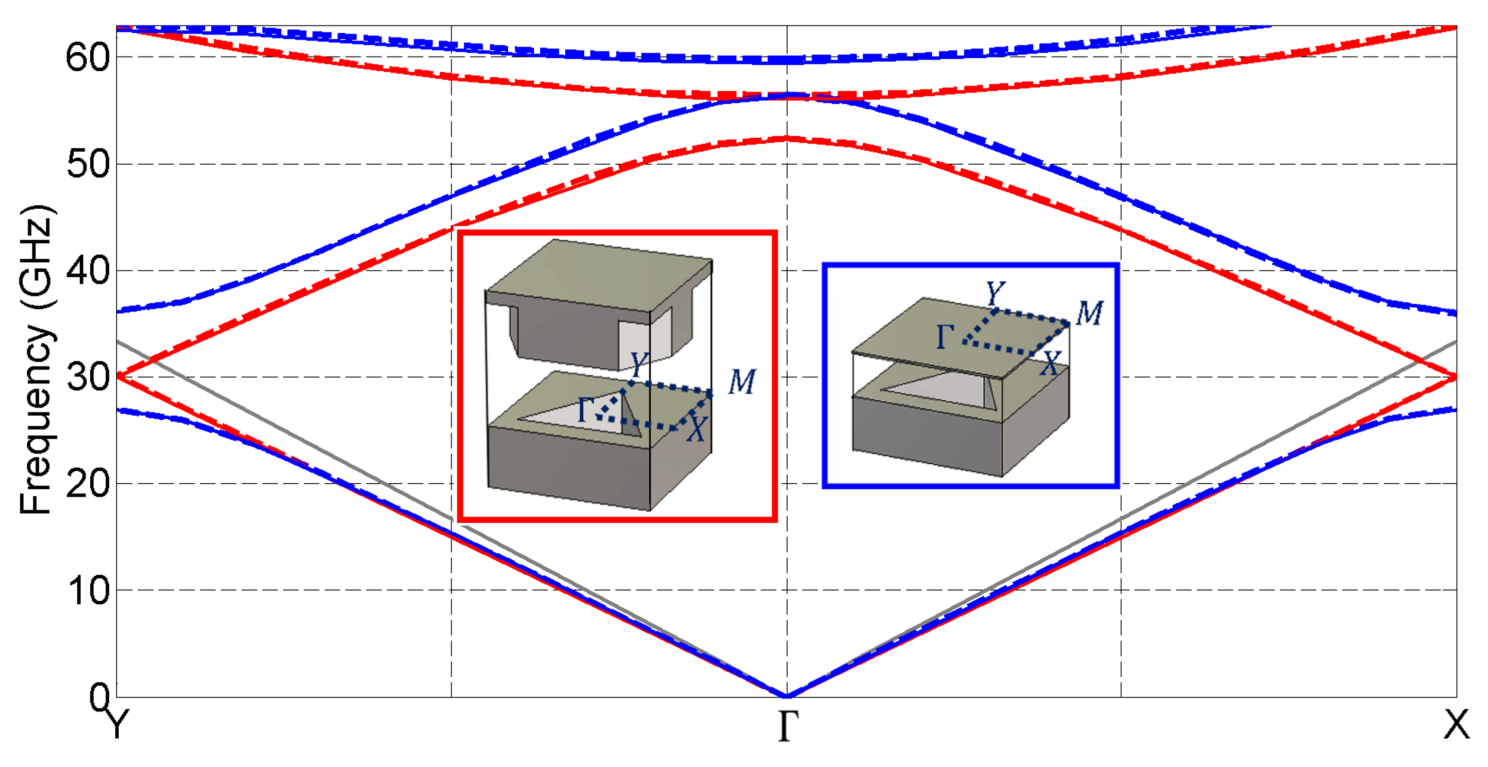
3.1. Dispersion Diagram

In order to simplify the analysis of the structure, a reference unit cell is defined with the following geometrical parameters: Period d x = d y = d = 4.5 mm, triangle height h t = 3 mm, hole depth h hole = 1.5 mm, gap height g = 0.5 mm, and relative permittivities ε r = ε r hole = 1 .
Figure 3 shows the dispersion diagrams of the mirror- and glide-symmetric unit cells. The interval Γ -X refers to wave propagation along the x-direction and Γ -Y to wave propagation along the y-direction. As shown in the figure, an excellent agreement is found between the results computed with the proposed mode-matching method (solid lines) and CST (dashed lines). The dispersion diagrams associated with the glide-symmetric structures are here plotted with red lines. In Figure 3, it can be appreciated that the stop band between the first and second modes disappears, as expected for this symmetric configuration. Furthermore, the frequency dispersion of propagating modes is considerably reduced compared to the mirror-symmetric structure (blue lines). Surprisingly, both configurations with mirror and glide symmetries present a very high isotropic behavior, despite the triangle is asymmetric in x and y directions with associated wave propagation paths clearly different. Specifically, the glide-symmetric structure exhibits a isotropic behavior in a wider range of frequencies. This issue will be treated in more detail in the next subsection.
Figure 4 shows the effects on the dispersion diagram of varying the size of the triangular hole ( h t ) in the mirror- and glide-symmetric configurations. As it can be noticed, both structures become denser (higher equivalent refractive index) as the triangle is larger, since its interaction with the propagating wave is greater. Additionally, the bandgap regions also become wider as the size of the hole increases.
In Figure 5, the influence of the gap height g on the dispersion diagram is analyzed. It is observed that the equivalent refractive index is inversely proportional to the gap height; namely, the structure is denser for smaller g. Additionally, the glide-symmetric configuration is denser compared to the mirror-symmetric one (i.e., the green curves at the Γ point show that the second mode propagates at lower frequencies in glide-symmetric cells). This fact was already exploited in [24] to increase the compression factor of a wideband Maxwell fish-eye lens made of glide-symmetric elliptical holes.
Finally, Figure 6 shows the influence of the hole depth h hole on the dispersion diagram. In this case, the equivalent refractive index is directly proportional to h hole ; that is, the structure is denser as the hole is deeper. Similarly to the findings in [21,23,24], once the depth is increased beyond a threshold value, h hole has no longer influence on the structure. This can be explained by the fact that the modes inside the hole are evanescent (operation frequency below the cutoff frequency of the triangular hole) and, therefore, they exponentially attenuate inside the hole without “reaching” the ground at the bottom of the hole, so that the position of this bottom ground has an almost negligible influence on the metasurface behavior.

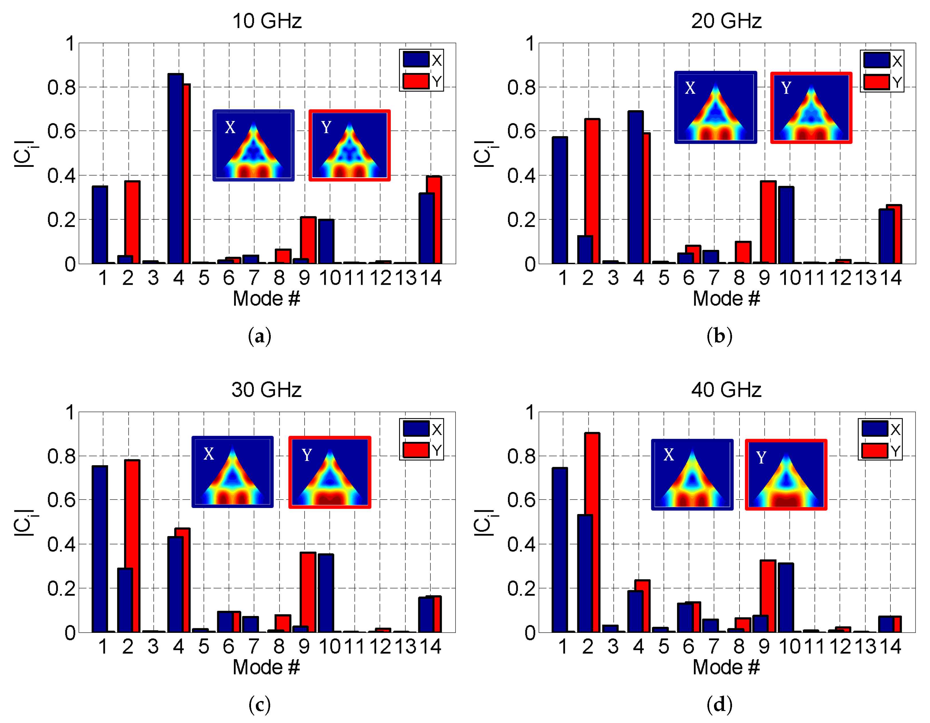
3.2. Isotropic Behavior
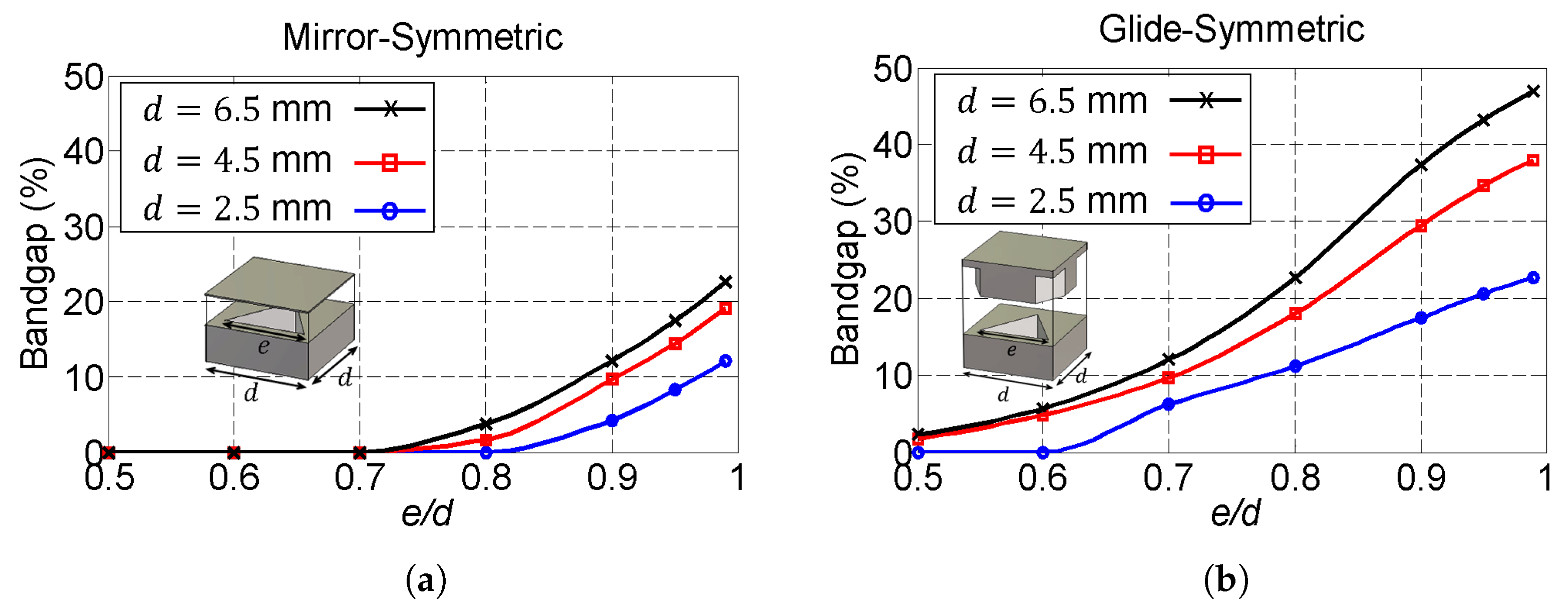
In this subsection, we give a physical insight on the unusual wave propagation isotropy observed in periodic structures with equilateral triangular holes. Firstly, we extend the analysis of wave propagation in x and y directions to all spatial directions (both k x d / π and k y d / π varying in the range [ 1 , 1 ] ). Figure 7 shows isofrequency color-map plots for the mirror- and glide-symmetric configurations. For the sake of conciseness, only the first propagating mode is considered in the color maps. Additionally, white-dashed circumferences have been included to easily compare the isotropy condition in both structures. As the isofrequency plots illustrate, both mirror- and glide-symmetric structures are quite isotropic for frequencies below 20 GHz ( h t / λ 0 < 1 / 5 ). Note that in the plots, radial color symmetry indicates perfect isotropy. However, as previously discussed in Section 3.1, the glide-symmetric configuration keeps the isotropy condition in a wider range of frequencies. The mirror-symmetric structure starts to show its anisotropic behavior near the stopband region (above 25 GHz), where the frequency dispersion is more evident. While less pronounced, the anisotropic behavior of the structure also becomes apparent at these frequencies in the glide-symmetric configuration, specially for wave propagation along the 45° direction ( k x = k y ).
The isotropic behavior of the structures can be related to the electrical size of the equilateral triangular hole and the cutoff frequency of the equivalent triangular waveguide. If the modal functions in the equilateral triangular waveguide are sorted according to their cutoff frequencies, the cutoff frequency of the first mode (labeled as #1 in Figure 2) is much higher compared to other canonical waveguides, such as the square or circular waveguides of the same lateral size [26,30]. This means that, in comparison with the same geometric size, the “effective” electrical size of the triangular hole is much smaller compared to other holes used in isotropic periodic holey structures. To illustrate this fact, let us consider an equilateral triangular waveguide whose side e is identical to the side of a square waveguide as well as to the diameter of a circular waveguide. The cutoff frequency of the first modal function in the triangular hole ( m = 1 , n = 0 ) filled with air is ( 2 c / 3 e ) / ( c / 2 e ) = 1.333 times higher than the cutoff of the fundamental mode of a square hole, and ( 2 c / 3 e ) / ( 1.8412 c / π e ) = 1.138 times higher than the cutoff of the fundamental mode of a circular hole. To further test this hypothesis, we compare in Figure 8 the dispersion features of our triangular structure with a benchmark holey metasurface whose holes have a double-ridged shape. The geometry of the holes are chosen so that their fundamental modes have the same cutoff frequency (60 GHz). Under this assumption, the size of the triangular hole is found to be much larger than the double-ridged hole. The same will be true for square and circular geometries, being the triangular hole one of the canonical geometries with higher cutoff frequency. Certainly, the propagation paths in x and y directions of the structure with double-ridged holes are different. Thus, this structure is expected to present a clear anisotropic behavior. However, at the low frequencies (below the hole cutoff at 60 GHz in the green region), both structures are quite isotropic. Only at frequencies above the hole cutoff frequency (red region), the shape of the hole has an impact on the anisotropy of the metasurface.
An additional physical mechanism can also contribute to enhance the isotropy in the low-frequency region of the dispersion diagram. In Figure 9 and Figure 10, we plot the magnitude of the C i “excitation” coefficient in (1) for the first 14 modes of the triangular hole. The analysis is performed at different frequencies: 10, 20 and 40 GHz for the mirror-symmetric configuration, and 10, 20, 30 and 40 GHz for the glide-symmetric configuration (the mirror-symmetric configuration being in stopband at 30 GHz). Therefore, these figures decompose the total field at the hole surface into the modal basis discussed in SubSection 2.2 and Figure 2. In the insets, we also plot the total transverse electric field when propagation occurs along the x and y directions. We observe that, at all the considered frequencies, the total field on the hole has the same distribution independently on the propagation direction. At low frequencies, the most excited mode is #4, while at higher frequencies modes #1 (when propagation is along x) and #2 (when propagation is along y) become gradually more important. This trend happens for both symmetric configurations. We should note that mode #4 is the fundamental TM mode and modes #1 and #2 are the first TE modes (this is clear in Figure 2). This fact agrees well with the findings reported in [25], where it was discussed that the presence of a metallic surface close to a holey metasurface requires to consider both the fundamental TE and TM modes when computing the field on a hole. In the present work, the most relevant modes have a rather symmetric behavior with respect to the center of the triangle, which gives rise to the excitation of basically the same total field independently of the propagation direction.

3.3. Bandgaps

A bandgap study of the mirror- and glide-symmetric periodic structures when varying the size of the hole (the triangle side e) and the period d of the unit cell is shown in Figure 11. The glide-symmetric configuration offers a wider bandwidth compared to the mirror-symmetric one, as also pointed out by previous studies on holey structures with circular [9] and elliptical [31] holes. Furthermore, the relative bandgap increases as the period of the unit cell is larger. Additionally, the relative bandgap is an increasing function of e / d ; that is, the larger the triangular hole, the larger the relative bandgap. This fact can be explained taking a look at the dispersion diagrams in Figure 4. At the Γ point of the mirror-symmetric configuration, the second mode approximately stays at the same frequency but the first mode decreases in frequency as the size of the hole increases, opening a wider bandgap. A similar behavior is also observed for the glide-symmetric configuration but considering now the second and third modes. Unlike what found for triangular holes, in the case of circular and elliptical holes [9,31], there is an optimum ratio between the size of the hole and the period at which the bandgap is maximum. Beyond that ratio, the relative bandgap starts to decay.
Figure 12 presents a bandgap study when varying the gap height g and the hole depth h hole for both the mirror- and glide-symmetric unit cells. In all cases under study, the glide-symmetric configuration offers a wider bandgap than the mirror-symmetric one. In both cases, the relative bandgap is inversely proportional to the gap height and directly proportional to the hole depth. Similarly to what was depicted in Figure 6, there is a threshold after which increasing the hole depth has no longer influence on the relative bandgap, since the modes exponentially attenuate inside the hole.

3.4. Applications

In this subsection we compare the major properties of different isotropic metastructures possessing glide symmetry. For this study, three glide-symmetric structures with triangular, circular, and square holes are considered. The results are summarized in Table 1 and Table 2.
As a comparison criterion for Table 1, we consider an equilateral triangular hole whose side e = 0.99 d , very close to the entire period, is identical to the side of a square hole as well as to the diameter of a circular hole. This is considered here as a "maximum" hole side. In order to calculate the frequency range in which the structures are regarded as isotropic and low-dispersive, we allow a maximum relative deviation of the refractive index of 5% with respect to its reference value at f 0 and propagating direction 0°. The analysis of the “isotropic” degree of the structure is carried out by comparing the dispersion properties in the propagating directions of 0° and 45°. For the maximum hole size, the triangular geometry offers the highest equivalent refractive index, as well as the least isotropic and low-dispersion bandwidth. Note that the circular hole is isotropic in a higher bandwidth compared to the other geometries; that is, it is less dispersive for different propagating directions. This could be associated to the rotational symmetry that possesses. Additionally, we calculate the maximum achievable bandgap in the three structures. In this calculation of the bandgap, the trends are different in the square, circular, and triangular holes. As previously discussed, the circular and square holes have an optimal value that maximizes the bandgap and beyond this value, the bandgap starts to close. As a consequence, in the case of maximum hole size, the bandgap within the first four propagating modes is very narrow in the case of circular and square holes (null in the case of the square geometry). However, in the case of the triangular hole, the bigger the hole is, the wider the bandgap. For this reason, the triangular geometry offers a wide bandgap when fixing the maximum hole size as a comparison criterion.
In Table 2 we compare the optimal values of glide-symmetric structures with triangular, circular and square holes. We carry out a parameter sweep in order to find the hole sizes associated with the optimal major properties of the three structures. In order to compute the optimal bandwidths, a maximum deviation of the refractive index of 5% is allowed. However, we should remark that any other comparison criterion, as fixing the same refractive index in all the structures and looking for the optimal bandwidths, would have been equally valid. According to the results shown in Table 2, the square hole offers the highest equivalent refractive index (it is the densest structure) as well as the widest stopband. The triangular hole shows similar characteristics (high equivalent refractive index and wide bandgap), being less frequency-dispersive than the square hole. Furthermore, the circular hole is isotropic and low-dispersive in a larger bandwidth compared to the triangular and square geometries, as also pointed out in Table 1.
The potential application of the different structures can readily be inferred from the properties observed in Table 1 and Table 2. Thus, square holes arranged in a glide-symmetric configuration are good candidates for the design of EBG (electromagnetic bandgap) structures, because of the widest stopband they offer. Circular holes are easier to fabricate and cost-effective compared to triangular and square holes, specially if the drilling technique is considered. For this reason, they have been widely used in the design of EBG structures, despite square and triangular holes offer a wider stopband. Additionally, the frequency dispersion of the structure with circular holes is lower compared to triangular and square geometries. Furthermore, Table 1 shows that the glide-symmetric configurations with triangular and square holes are denser (higher equivalent refractive index) than the configuration that uses circular holes. This feature is very suitable for the design of graded-index metalenses (metamaterial lenses).

4. Conclusions

In this paper we have applied a mode-matching formulation to analyze the wave propagation in periodic metallic structures with equilateral triangular holes. We have studied the influence of the geometrical parameters of the unit cell in both mirror- and glide-symmetric configurations. The outcomes of this study have confirmed some the advantages of glide symmetry in relation to the mirror-symmetric structure; namely, reduced frequency dispersion, wider bandwidth, higher equivalent refractive index, and wider stopband. Interestingly, we have also noticed unexpected isotropic behavior from both mirror- and glide-symmetric triangular holey configurations. Since this behavior appears in both configurations, we associated the isotropic behavior to the triangular geometry rather than to the symmetry of the unit cell. A physical insight on the matter has shown that the cause of that isotropic behavior is two-fold. First, the reduced electrical size (high cutoff frequency) of the triangular hole compared to other canonical geometries such as the square or circle. Second, the particular distribution of the most significant modes in the modal basis at the lowest frequencies, which makes possible the excitation of the same total field in the hole independently of the propagation direction.

Author Contributions

Conceptualization, A.A.-A., G.V., F.M., O.Q.-T.; methodology and formal analysis, F.G., G.V., A.A.-A.; programming and software, A.A.-A.; resources, J.M.F.-G., P.P., O.Q.-T.; writing-original draft, A.A.-A., G.V.; supervision, P.P., J.M.F.-G., O.Q.-T.; funding acquisition, P.P., J.M.F.-G., O.Q.-T. All the authors review and edit the document. All authors have read and agreed to the published version of the manuscript.

Funding

This work was partially funded by the Spanish Ministerio de Ciencia Innovación y Universidades under the project TIN2016-75097-P, and with European Union FEDER funds under projects TEC2017-84724-P and TEC2017-85529-C3-1-R, by the French National Research Agency Grant Number ANR-16-CE24-0030, by the Vinnova project High-5 (2018-01522) under the Strategic Programme on Smart Electronic Systems, and by the Stiftelsen Åforsk project H-Materials (18-302).

Conflicts of Interest

The authors declare no conflict of interest.

References

  1. Pendry, J.B.; Martin-Moreno, L.; García-Vidal, F.J. Mimicking Surface Plasmons with Structured Surfaces. Science 2004, 305, 847–848. [Google Scholar] [CrossRef] [PubMed]
  2. Quesada, R.; Martín-Cano, D.; García-Vidal, F.J.; Bravo-Abad, J. Deep-subwavelength negative-index waveguiding enabled by coupled conformal surface plasmons. Opt. Lett. 2014, 39, 2990–2993. [Google Scholar] [CrossRef] [PubMed]
  3. Collin, R.E. Field Theory of Guided Waves, 2nd ed.; IEEE Press: New York, NY, USA, 1990. [Google Scholar]
  4. Ishimaru, A. Electromagnetic Wave Propagation, Radiation, and Scattering; Prentice Hall: Upper Saddle River, NJ, USA, 1991. [Google Scholar]
  5. Tang, W.X.; Zhang, H.C.; Ma, H.F.; Jiang, W.X.; Cui, T.J. Concept, Theory, Design, and Applications of Spoof Surface Plasmon Polaritons at Microwave Frequencies. Adv. Opt. Mater. 2019, 7, 1800421. [Google Scholar] [CrossRef] [Green Version]
  6. Meng, W.; Ma, H.F.; Tang, W.X.; Sun, S.; Cui, T.J. Leaky-Wave Radiations with Arbitrarily Customizable Polarizations Based on Spoof Surface Plasmon Polaritons. Phys. Rev. Appl. 2019, 12, 11. [Google Scholar]
  7. Quevedo-Teruel, O.; Ebrahimpouri, M.; Ng Mou Kehn, M. Ultrawideband metasurface lenses based on off-shifted opposite layers. IEEE Antennas Wirel. Propag. Lett. 2016, 15, 484–487. [Google Scholar] [CrossRef]
  8. Ghasemifard, F.; Norgren, M.; Quevedo-Teruel, O. Dispersion analysis of 2D glide-symmetric corrugated metasurfaces using mode-matching technique. IEEE Microw. Wirel. Compon. Lett. 2018, 28, 1–3. [Google Scholar] [CrossRef]
  9. Ebrahimpouri, M.; Quevedo-Teruel, O.; Rajo-Iglesias, E. Design Guidelines for Gap Waveguide Technology Based on Glide-Symmetric Holey Structures. IEEE Microw. Wirel. Compon. Lett. 2017, 27, 542–544. [Google Scholar] [CrossRef]
  10. Monje-Real, A.; Fonseca, N.J.G.; Zetterstrom, O.; Pucci, E.; Quevedo-Teruel, O. Holey glide-symmetric filters for 5G at millimeter-wave frequencies. IEEE Microw. Wirel. Compon. Lett. 2020, 30, 31–34. [Google Scholar] [CrossRef]
  11. Ebrahimpouri, M.; Quevedo-Teruel, O. Ultrawideband anisotropic glide-symmetric metasurfaces. IEEE Antennas Wirel. Propag. Lett. 2019, 18, 1547–1551. [Google Scholar] [CrossRef]
  12. Ebrahimpouri, M.; Herran, L.F.; Quevedo-Teruel, O. Wide angle impedance matching using glide-symmetric metasurfaces. IEEE Microw. Wirel. Compon. Lett. 2020, 30, 8–11. [Google Scholar] [CrossRef]
  13. Palomares-Caballero, A.; Padilla, P.; Alex-Amor, A.; Valenzuela-Valdés, J.; Quevedo-Teruel, O. Twist and glide symmetries for helix antenna design and miniaturization. Symmetry 2019, 11, 349. [Google Scholar] [CrossRef] [Green Version]
  14. Palomares-Caballero, A.; Alex-Amor, A.; Padilla, P.; Luna, F.; Valenzuela-Valdés, J. Compact and Low-Loss V-band Waveguide Phase Shifter Based on Glide-Symmetric Pin Configuration. IEEE Access 2019, 7, 31297–31304. [Google Scholar] [CrossRef]
  15. Quevedo-Teruel, O.; Miao, J.; Mattsson, M.; Algaba-Brazalez, A.; Johansson, M.; Manholm, L. Glide-symmetric fully metallic Luneburg lens for 5G communications at Ka-band. IEEE Antennas Wirel. Propag. Lett. 2018, 17, 1588–1592. [Google Scholar] [CrossRef]
  16. Ebrahimpouri, M.; Rajo-Iglesias, E.; Sipus, Z.; Quevedo-Teruel, O. Cost-effective gap waveguide technology based on glide-symmetric holey EBG structures. IEEE Trans. Microw. Theory Technol. 2018, 66, 927–934. [Google Scholar] [CrossRef] [Green Version]
  17. Ebrahimpouri, M.; Brazalez, A.A.; Manholm, L.; Quevedo-Teruel, O. Using glide-symmetric holes to reduce leakage between waveguide flanges. IEEE Microw. Wirel. Compon. Lett. 2018, 28, 473–475. [Google Scholar] [CrossRef]
  18. Rajo-Iglesias, E.; Ebrahimpouri, M.; Quevedo-Teruel, O. Wideband phase shifter in groove gap waveguide technology implemented with glide-symmetric holey EBG. IEEE Microw. Wirel. Compon. Lett. 2018, 28, 476–478. [Google Scholar] [CrossRef]
  19. Padilla, P.; Palomares-Caballero, A.; Alex-Amor, A.; Valenzuela-Valdés, J.; Fernández-González, J.M.; Quevedo-Teruel, O. Broken glide-symmetric holey structures for bandgap selection in gap-waveguide technology. IEEE Microw. Wirel. Compon. Lett. 2019, 29, 327–329. [Google Scholar] [CrossRef]
  20. Liao, Q.; Rajo-Iglesias, E.; Quevedo-Teruel, O. Ka-band fully metallic TE40 slot array antenna with glide-symmetric gap waveguide technology. IEEE Trans. Antennas Propag. 2019, 67, 6410–6418. [Google Scholar] [CrossRef]
  21. Valerio, G.; Ghasemifard, F.; Sipus, Z.; Quevedo-Teruel, O. Glide-Symmetric All-Metal Holey Metasurfaces for Low-Dispersive Artificial Materials: Modeling and Properties. IEEE Trans. Microw. Theory Technol. 2018, 66, 3210–3223. [Google Scholar] [CrossRef] [Green Version]
  22. Ghasemifard, F. Periodic Structures with Higher Symmetries: Analysis and Applications. Ph.D. Thesis, KTH Royal Institute of Technology, Stockholm, Sweden, 2018. [Google Scholar]
  23. Ghasemifard, F.; Norgren, M.; Quevedo-Teruel, O.; Valerio, G. Analyzing Glide-Symmetric Holey Metasurfaces Using a Generalized Floquet Theorem. IEEE Access 2018, 6, 71743–71750. [Google Scholar] [CrossRef]
  24. Alex-Amor, A.; Ghasemifard, F.; Valerio, G.; Ebrahimpouri, M.; Padilla, P.; Fernández-González, J.M.; Quevedo-Teruel, O. Glide-Symmetric Metallic Structures with Elliptical Holes for Lens Compression. IEEE Trans. Microw. Theory Technol. 2019. submitted. [Google Scholar]
  25. Valerio, G.; Sipus, Z.; Grbic, A.; Quevedo-Teruel, O. Non-resonant modes in plasmonic holey metasurfaces for the design of artificial flat lenses. Opt. Lett. 2017, 42, 2026–2029. [Google Scholar] [CrossRef] [PubMed] [Green Version]
  26. Morán-López, A.; Córcoles, J.; Ruiz-Cruz, J.A.; Montejo-Garai, J.R.; Rebollar, J.M. Electromagnetic Scattering at the Waveguide Step between Equilateral Triangular Waveguides. Adv. Math. Phys. 2016, 2016, 2974675. [Google Scholar] [CrossRef] [Green Version]
  27. Schelkunoff, S.A. Electromagnetic Waves; D. Van Nostrand Company: New York, NY, USA, 1943. [Google Scholar]
  28. Wang, C.Y. Exact solution of equilateral triangular waveguide. Electron. Lett. 2010, 46, 925–927. [Google Scholar] [CrossRef]
  29. Milton, K.A.; Schwinger, J. Rectangular and Triangular Waveguides. In Electromagnetic Radiation: Variational Methods, Waveguides and Accelerators; Springer: Berlin/Heidelberg, Germany, 2006. [Google Scholar]
  30. Morán-López, A.; Córcoles, J.; Ruiz-Cruz, J.A.; Montejo-Garai, J.R.; Rebollar, J.M. Dual-mode filters in equilateral triangular waveguides with wide spurious-free response. In Proceedings of the 2017 IEEE MTT-S International Microwave Symposium (IMS), Honololu, HI, USA, 4–9 June 2017; pp. 1192–1195. [Google Scholar]
  31. Tamayo-Domínguez, A.; Fernández-González, J.M.; Quevedo-Teruel, O. One-Plane Glide-Symmetric Holey Structures for Stop-Band and Refraction Index Reconfiguration. Symmetry 2019, 11, 495. [Google Scholar] [CrossRef] [Green Version]
Figure 1. (a) Mirror-Symmetric and (b) glide-symmetric periodic metallic structures with equilateral triangular holes and a zoom showing their unit cells.
Applsci 10 01600 g001
Figure 2. Normalized magnitude of the tangential modal functions in the equilateral triangular waveguide.
Applsci 10 01600 g002
Figure 3. Dispersion diagram of the glide-symmetric (red lines) and mirror-symmetric (blue lines) unit cells. Dashed lines represent the results extracted from CST and solid lines the results extracted from the mode-matching. The light line is displayed in gray.
Applsci 10 01600 g003
Figure 4. Dispersion diagram of the (a) mirror-symmetric and (b) glide-symmetric unit cells when varying the height of the triangle. Dashed lines represent the results extracted from CST and solid lines the results extracted from the mode-matching. The light line is displayed in gray. The geometrical parameters of the unit cells are: h hole = 1.5 mm, g = 0.5 mm, and d x = d y = 4.5 mm.
Applsci 10 01600 g004
Figure 5. Dispersion diagram of the (a) mirror-symmetric and (b) glide-symmetric unit cells when varying the gap between the metallic plates. Dashed lines represent the results extracted from CST and solid lines the results extracted from the mode-matching. The light line is displayed in gray. The geometrical parameters of the unit cells are: h hole = 1.5 mm, h t = 3 mm, and d x = d y = 4.5 mm.
Applsci 10 01600 g005
Figure 6. Dispersion diagram of the (a) mirror-symmetric and (b) glide-symmetric unit cells when varying the hole depth. Dashed lines represent the results extracted from CST and solid lines the results extracted from the mode-matching. The light line is displayed in gray. The geometrical parameters of the unit cells are: g = 0.5 mm, h t = 3 mm, and d x = d y = 4.5 mm.
Applsci 10 01600 g006
Figure 7. Isofrequency plot for the (a) mirror-symmetric and (b) glide-symmetric configurations. To compare the isotropy level, perfect circles are marked in white. The geometrical parameters of the unit cells are: g = 0.2 mm, h t = 3 mm, h hole = 1.5 mm, and d x = d y = 4.5 mm.
Applsci 10 01600 g007
Figure 8. Dispersion diagram of two mirror-symmetric structures with triangular (black lines) and double-ridged (red lines) holes. The right panel shows a detail of the double-ridged hole. The light line is displayed in gray. The cutoff frequency of the triangular and double-ridged waveguides is chosen to be the same, f c = 60 GHz. Independently of the shape of the holes, the anisotropy of the structures is hardly noticeable below the cutoff frequency (green region). The geometrical parameters of the unit cells are: h hole = 1.5 mm, g = 0.2 mm, d x = d y = 4.5 mm, h t = 2.88 mm, a 1 = b 2 = 1.46 mm, and a 2 = b 1 = a 1 / 3 .
Applsci 10 01600 g008
Figure 9. Normalized magnitude of the coefficients C i in the mirror-symmetric configuration for wave propagation in x and y directions at different frequencies: (a) 10 GHz, (b) 20 GHz, (c) 40 GHz. The normalized magnitude of the tangential electric field, calculated according to Equation (1), is also displayed for both propagating directions. The geometrical parameters of the considered unit cells are: h h o l e = 1.5 mm, g = 0.2 mm, h t = 3 mm, and d x = d y = 4.5 mm. The dispersion diagram of the structure is displayed in the green curve of Figure 5a.
Applsci 10 01600 g009
Figure 10. Normalized magnitude of the coefficients C i in the glide-symmetric configuration for wave propagation in x and y directions at different frequencies: (a) 10 GHz, (b) 20 GHz, (c) 30 GHz, (d) 40 GHz. The normalized magnitude of the tangential electric field, calculated according to (1), is also displayed for both propagating directions. The geometrical parameters of the considered unit cells are: h h o l e = 1.5 mm, g = 0.2 mm, h t = 3 mm, and d x = d y = 4.5 mm. The dispersion diagram of the structure is displayed in the green curve of Figure 5b.
Applsci 10 01600 g010
Figure 11. Relative bandgap in the (a) mirror-symmetric and (b) glide-symmetric structures with equilateral triangular holes as a function of the period d and the triangle side e. The geometrical parameters of the considered unit cells are: h hole = 1.5 mm, and g = 0.2 mm.
Applsci 10 01600 g011
Figure 12. Relative bandgap in the (a) mirror-symmetric and (b) glide-symmetric structures with equilateral triangular holes as a function of the gap height g and the hole depth h hole . The geometrical parameters of the considered unit cells are: h t = 3.8 mm, and d = 4.5 mm.
Applsci 10 01600 g012
Table 1. Comparison among different metastructures possessing glide symmetry for the maximum hole size. For each line, the frequency values in the columns “Anisotropy” and “Dispersion” correspond to the maximum frequency that shows a deviation less than 5% with respect to the value at f = 0 . The geometrical parameters of the unit cells are: h hole = 1.5 mm, g = 0.2 mm, and d x = d y = 4.5 mm.
HOLE SHAPEAnisotropy
(<5%)
Refr. Index
(@10 GHz)
Dispersion
(<5%)
Bandgap (%)
Triangular16.20 GHz1.3125.71 GHz39.50
Circular28.86 GHz1.1746.04 GHz0
Square22.98 GHz1.2132.10 GHz6.81
Table 2. Comparison among the optimal values of different metastructures possessing glide symmetry. The geometrical parameters of the unit cells are: h hole = 1.5 mm, g = 0.2 mm, and d x = d y = 4.5 mm. The optimal values for the triangular hole are: Min. Iso. Range, Max. Refr. Index, Min. Low-Disp. Range and Max. Bandgap ( e = 0.99 d ). The optimal values for the circular hole are: Min. Iso. Range ( 2 r circle = 0.78 d ), Max. Refr. Index ( 2 r circle = 0.85 d ), Min. Low-Disp. Range ( 2 r circle = 0.85 d ), and Max. Bandgap ( 2 r circle = 0.78 d ). The optimal values for the square hole are: Min. Iso. Range ( l square = 0.71 d ), Max. Refr. Index ( l square = 0.76 d ), Min. Low-Disp. Range ( l square = 0.76 d ), and Max. Bandgap ( l square = 0.71 d ).
HOLE SHAPEMin. Iso.
Range
Max. Refr. Index
(@10 GHz)
Min. Low-Disp.
Range
Max. Bandgap
(%)
Triangular16.20 GHz1.3125.71 GHz39.50
Circular24.76 GHz1.2334.41 GHz22.55
Square19.85 GHz1.3421.76 GHz48.66

