Article

Analytical Model of Wellbore Stability of Fractured Coal Seam Considering the Effect of Cleat Filler and Analysis of Influencing Factors

1
School of Science, Qingdao University of Technology, Qingdao 266033, China
2
State Key Laboratory for Performance and Structure Safety of Petroleum Tubular Goods and Equipment Materials, CNPC TubularGoods Research Center, Xian 710077, China
3
State Key Laboratory of Structural Analysis for Industrial Equipment, Department of Engineering Mechanics, Dalian University of Technology, Dalian 116023, China
4
International Research Center for Computational Mechanics, Dalian University of Technology, Dalian 116023, China
*
Author to whom correspondence should be addressed.
Appl. Sci. 2020, 10(3), 1169; https://doi.org/10.3390/app10031169
Submission received: 23 December 2019 / Revised: 29 January 2020 / Accepted: 30 January 2020 / Published: 9 February 2020
(This article belongs to the Special Issue Fracture and Fatigue Assessments of Structural Components)

Abstract

:
Currently, coal borehole collapses frequently occur during drilling. Considering that the coal near to the wellbore is cut into blocks, and the cleat filler of the coal influences the stress distribution near the wellbore, a new theoretical solution of a near-wellbore Stress Field in coal bed wells is established. In addition, according to the limit equilibrium theory and the E.MG-C criterion, the limit sliding formula of the quadrilateral and triangular block is deduced, and the slipping direction of the blocks is further judged. Finally, the wellbore stability model of the coal seam is established. The accuracy of the theoretical model is verified through a numerical method by using the PFC software. Based upon this wellbore stability theoretical model of coal, many cleat affecting factors such as cleat spacing, cleat length, cleat angle and the cleat geometric position, are studied, and the results show that a quadrilateral block slides off more easily than a triangular block under the same boundary condition; the bigger the cleat spacing and cleat length are, the lower is the risk that blocks slide off, and increasing the cleat angle could cause blocks to slide off easily. Under the same boundary condition, whether blocks slide off or not is closely related to the well round angle.

1. Introduction

It is an essential part of the unconventional development of energy to exploit coalbed methane in China [1]. Under the condition of natural strata, the coalbed presents its discontinuous and fragile properties, due to the limitation of the structural characteristics, such as natural fracture extension, abundant cleat system, low elastic modulus and strong anisotropy [2,3]. When the drilling contacts with this kind of broken coal seam, it tends to cause the collapse of the coal wellbore by the disturbance of the drilling string and the intrusion of the drilling fluid [4,5,6]. Until now, many specialists have carried out a number of studies about the stability of the sandstone wall through the continuum theory, which is useful for quasi-continuous reservoirs, such as sandstone, but is not useful for a broken coal seam. So, it is urgent to study the mechanism of the wellbore instability of the broken coal seam.
Specialists have achieved a number of results [7,8,9,10] on the study of the wellbore stability of oil and gas wells, which can give us ideas on solving the problems of a broken coal seam. Zhang et al. [11] proposed the coupling system of both flow and solid in rock failure process analysis, in order to study how the size-effect of a horizontal wellbore in a coal seam impacts on wellbore stability by RFPA2D. Chu and Shen et al. [12,13,14] proposed fracture mechanics and a 3-D discrete element method to analyze the mechanical properties of the coal bed methane wellbore stability and the method to determine the window of drilling fluid density. Since the coal seam was non-continuum, Chen et al. [15] established the discrete element model of the collapse pressure of a coal seam based on non-continuum mechanics considering mud intrusion strata. Zhu et al. [16] proposed the model of coal seam wellbore stability based on the discrete element method. Qu et al. [17] presented the evaluation model of borehole stability in a coal seam by using a stress intensity factor to describe the concentrative degree of crack stress. Zhao and Zhang et al. [18,19] concluded the stress field expression around the broken coal seam wellbore by considering the cleat as the crack and computing the additional stress fields of cracks. But those papers did not distinguish the differences between the cracks and cleats of coals and rocks [20]. Cracks are fractures which can easily separate from each other, and cleats are endogenetic fractures, and this means that they contain fillers in the fracture gap space. Through the researches, the impact of the cleat filler and its connected state on the stress field around the entire wellbore were critical [21]. Through reviewing related literatures and materials, cleats are divided into full filled cleats, filled cleats and unfilled cleats [22]. Therefore, the impact on the near stress field of the cleat filler around the entire wellbore could not be eliminated.
According to the current literature review, it was extremely regular that the previous approaches were calculated by simplification; for example, the cleat system included in the above analytical model was extremely regular, and additionally, they did not distinguish the differences between the cleat system and the crack system, which is quite different from the actual cleat. Thus, it would cause a significant error in the result. Given the irregularity of the fracture distribution in broken coal seams and the impact of the cleat filler, the stress field theory model of the broken coal seam wellbore is established, which considers the influence of the cleat filler. In this paper, the stability model of the broken coal seam wellbore is established, which evaluates the block sliding near the wellbore, by introducing the E.MG-C criterion and the limit equilibrium method to analyze the strength failure and tensile resistance of the cleats. The sliding condition of the triquetrous block and the quadrilateral block are also taken into account, and the accuracy of the analytical model is verified through a numerical method by the Particle Flow Code (PFC) software.

2. Stability Model of Fracture Coal Seam Wall

One of the important features of fractured coal seams is that the coal seams contain a large number of cut fractures. These cleat fractures destroy the integrity of the coal seams, as shown in Figure 1, and cut the coal seams into the quadrilateral blocks, trilateral blocks and a few polygonal blocks. As shown in Figure 1, the quadrilateral block includes the block 1, 7, 8, and the triangular block includes the block 2, 4, 6, 9. As their falling depends on whether their adjacent blocks fall off, the block 3 and 5 are not taken into account. Considering that the axial deformation of the borehole is approximately 0, the stress field around the borehole can be simplified to the plane strain state. In the plane, the wall surrounding rock is affected by non-uniform stress σH, σh, drilling fluid pressure P0 and the induced stress caused by the cracks.

3. Stress Analysis of the Wellbore Surrounding Rocks in Broken Coal Seams

3.1. Stress Analysis of the Wellbore Surrounding Rocks as a Continuous Body

In order to obtain the stress distribution of broken coal seams, firstly we assume that the coal rock is a continuous body. Then, the stress field around the wall of the well can be obtained under non-uniform, in-situ stress and wellbore pressure P0:
{ σ r = σ m [ 1 ( r R 0 ) 2 ] σ n [ 1 3 ( r R 0 ) 2 + 3 ( r R 0 ) 4 ] cos 2 θ ( r R 0 ) 2 P 0 α Biot P 0 σ θ = σ m [ 1 + ( r R 0 ) 2 ] + σ n [ 1 + 3 ( r R 0 ) 4 ] cos 2 θ + ( r R 0 ) 2 P 0 α Biot P 0 τ r θ = σ n [ 1 + 2 ( r R 0 ) 2 3 ( r R 0 ) 4 ] sin 2 θ ,
where σr, σθ, τ, are radial stress, cyclic stres, and shear stress under polar coordinates, respectively. 2σm = σH + σh, 2σn = σHσh; R0 is the wellbore radius; r is the length of the calculation point to the wellbore central axis; θ is the wellbore angle; αBiot is Biot coefficient.
Then wellbore rock displacement [23] can be expressed as follows, and the specific derivation process of the formula can be referred to paper 23:
{ u r = 1 + μ r E R 2 2 R 0 2 ( P 0 ( 1 2 μ ) σ m ) + ( 1 2 μ ) P 0 r 2 R 2 2 σ m r 2 R 2 2 R 0 2 + 2 cos 2 θ 5 E [ ( 12 6 μ ) K 1 r 3 ( 1 + μ ) K 2 r + ( 6 + 4 μ ) K 3 / r + 9 ( 1 + μ ) K 4 / r 3 ] u θ = 6 sin 2 θ 5 E [ ( 3 + μ ) K 1 r 3 + ( 1 + μ ) K 2 r ( 1 μ ) K 3 / r + ( 1 + μ ) K 4 / r 3 ] ,
where E, μ are the elastic modulus and Poisson’s ratio of coal seam under plane strain conditions, respectively; u r , u θ are the radial displacement and the cyclic displacement, respectively; R2 is the radius of the circular outer boundary set for the solution, R 2 R 0 ; K is a constant coefficient determined by the geometric size of the model. Its specific calculation formula can be written as Equation (3):
[ 0 1 2 R 0 2 3 R 0 4 3 R 0 2 1 1 R 0 2 3 R 0 4 0 2 4 R 2 2 6 R 2 4 6 R 2 2 2 2 R 2 2 6 R 2 4 ] { K 1 K 2 K 3 K 4 } = { 0 0 σ n σ n } ,
The displacement field under the polar coordinates obtained by Equation (2) can be changed to the displacement field under the orthogonal Cartesian coordinate system by the coordinate transformation method. The transformed displacement component can be expressed as u x and u y , and the transformation process is shown in Equation (4).
{ u x u y } = [ cos θ sin θ sin θ cos θ ] { u r u θ } ,

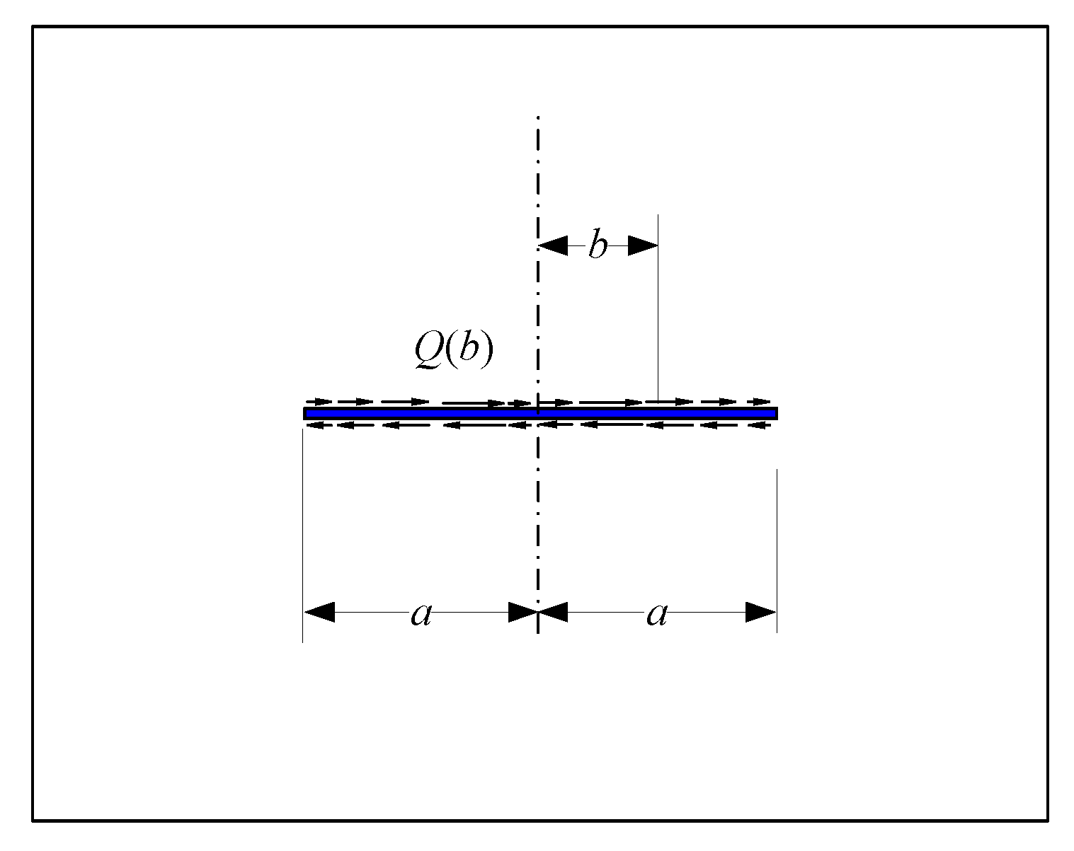
3.2. Induced Stress Analysis

According to the research, we find that the internal filling material is not completely filled, and it appears to be intermittent along the orientation of the cleat direction. Therefore, it could be assumed that the filler is composed of multiple rod structures, which is like a spring, as shown in Figure 2. There is no connection between these rods. The strong effect of the rod structure is only connected with the upper side Γ 1 and the lower side Γ 2 on the cleat. When the normal displacement occurs on both sides of the cleat, the filler can be considered as a rod structure. When the cleat surface undergoes a tangent displacement, the filler can be considered as a beam structure.
Therefore, under the external loading, the relationship between the filler and the normal load P and the tangent load Q generated on the cleat surface, and the relative displacement on both sides of the cleat surface, can be written as [24]:
P = E F | u y Γ 1 u y Γ 2 | D F ,
Q = E F d b 4 | u x Γ 1 u x Γ 2 | D F 3 ,
where, EF is the elastic modulus of the cleat filler; x , y are directions along the cleat and the vertical cleat, respectively; u x and u y are displacements in the x and y directions, respectively; db is the width of the filler, which can be set as the width of the unit; due to the length of the cleat, along the cleat direction, the normal load P and the tangent load Q will change with different positions, so the cleat load and the cleat distribution load are the function of positions, seen in Figure 3 and Figure 4.
According to the strength factor under a single normal load and a tangent load in the stress field intensity factor manual, and using the superposition principle, the strength factor under an asymmetric distribution load is obtained by integrating [25], seen in Equations (6)and (7):
K I = 1 π a a a a + b a b p ( b ) d b ,
K I I = 1 π a a a a + b a b Q ( b ) d b ,
Then the stress field expression near the crack tip can be written [25] in Equation (9):
{ σ x = K I 2 π ρ cos φ 2 ( 1 sin φ 2 sin 3 φ 2 ) K I I 2 π ρ sin φ 2 ( 2 + cos φ 2 cos 3 φ 2 ) σ y = K I 2 π ρ cos φ 2 ( 1 + sin φ 2 sin 3 φ 2 ) + K I I 2 π ρ sin φ 2 cos φ 2 cos 3 φ 2 τ x y = K I 2 π ρ sin φ 2 cos φ 2 cos 3 φ 2 + K I I 2 π ρ cos φ 2 ( 1 sin φ 2 sin 3 φ 2 ) ,
where, σ x , σ y and τ x y are the normal stress and the shearing stress in the additional stress field, respectively. The stress state is shown in Figure 5, where ρ, φ are the radius and angle of the point to the cleat tip, respectively.
The induced displacement field distribution near the cutting tip can be written as [23]:
{ u x = K I 2 G ρ 2 π cos φ 2 ( κ 1 + 2 sin 2 φ 2 ) + K I I 2 G ρ 2 π sin φ 2 ( κ + 1 + 2 cos 2 φ 2 ) u y = K I 2 G ρ 2 π sin φ 2 ( κ + 1 2 cos 2 φ 2 ) + K I I 2 G ρ 2 π cos φ 2 ( κ 1 2 sin 2 φ 2 ) ,
where G represents the shear elastic modulus; κ = 3 μ 1 + μ .
Thus, it can be obtained that the total displacement field of coal seam considering the cleats can be expressed as:
{ u x = u x + u x u y = u y + u y ,
Through the change of coordinates, the relationship between the displacement field and the total displacement field of coal rocks can be obtained:
{ u x u y } = [ cos ϕ sin ϕ sin ϕ cos ϕ ] { u x u y } ,
where ϕ is the cutting inclination.
Through the simultaneous Equations (2), (5), (8), (10) and (11), the specific solution can be obtained. In this paper, we propose a program to gain the result of the above formula, because Equations (5)–(8) and (10) keep positive correlation with displacement u x , u y . So, we firstly set the values of u x and u y , and next through the above formula, we can get other values of u x and u y . Then taking the result of the previous iteration as the initial value of the continued iteration, we stop iterating until the error between the former and the latter is within the allowable range.

3.3. The Total Stress Field of the Broken Coal Seam Wellbore Surrounding Rocks

The Equations (1) and (9) can be obtained by the stress field distribution of a non-continuous coal seam containing a single shearing. Equations (1) and (9) are in different coordinate systems. For this purpose, the calculation results need to be unified into the same coordinate system for superposition. The coordinate system of the axis X and Y with the σH and σh directions is the final coordinate system. The stress in Equations (1) and (9) are all converted to this coordinate system, and the stress expression of the non-continuous coal seam is obtained by superposition.
By extension, if n cleats exist in the coal seam, the stress States of σ x , σ y and τ x y at any point in the coal seam can be expressed as:
{ σ x σ y τ xy } = [ cos 2 θ sin 2 θ sin 2 θ sin 2 θ cos 2 θ sin 2 θ sin 2 θ 2 sin 2 θ 2 cos 2 θ ] { σ r σ θ τ r θ } +   i = 1 n   [ cos 2 ϕ i sin 2 ϕ i sin 2 ϕ i sin 2 ϕ i cos 2 ϕ i sin 2 ϕ i sin 2 ϕ i 2 sin 2 ϕ i 2 cos 2 ϕ i ] { σ x i σ y i τ x y i }     ,
where σ x i , σ y i , and τ x y i are the induced stress fields caused by the i cutting, respectively; ϕ i is the direction of section i.

4. Stable Analysis of Wellbore Coal Rocks

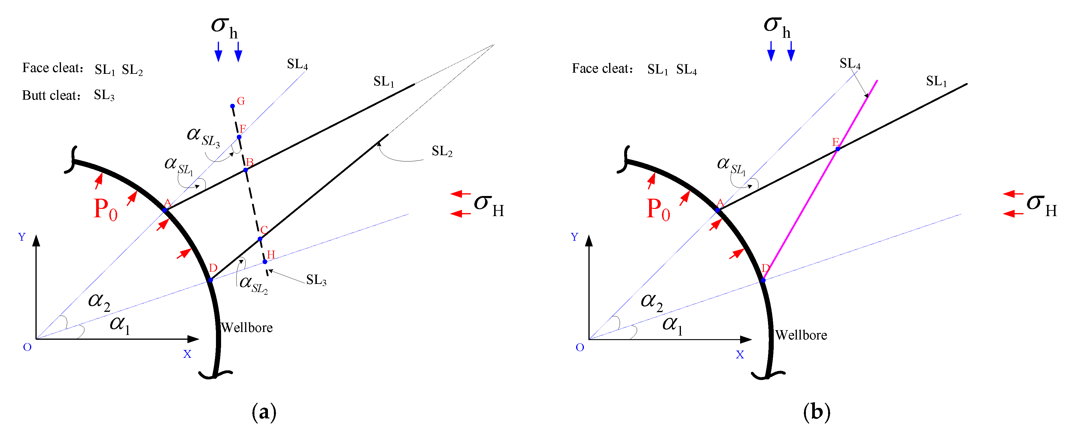
4.1. The Theory of Block Slip and the Determination of Movable Block

The rock in the engineering structure tends to be divided into different shapes by faults, joints, or weak interlayers. Because the strength of the joints and weak interlayers is weaker than the strength of the rock body, the damage of the engineering structure can be attributed to the sliding damage of rocks along the joint surface and the weak interlayer plane, and both the damage and the deformation of rocks are basically ignored.
The block slip theory assumes that the through structure surface is a spatial plane, the mosaic block body is regarded as a convex body, and the various loads of the structure surface are regarded as a spatial vector. Under the conditions of each spatial plane, the geometric method is used to pass simple static force calculation. Then, using the vector operation algorithm, the force of each plane of the mosaic block is summed up by vectors, and the sliding force of the mosaic block instability is obtained. Due to natural cutting, the coal rock is cut into finite rock bodies and infinite rock bodies. The finite rock blocks are divided into movable rock bodies and immovable rock bodies. The key to block theory is to determine the movable blocks.
Through the research, it is found that the parameters that determine the motility of the blocks mainly include the shear plane parameters and the geometric parameters of the near-empty plane. By moving the half-space interface of the constituent block to the coordinate zero point, a series of cones can be formed: the crack cone (CP) is a cone formed by the semi-space of the thermal fracture plane, and the excavation cone (EP) is a cone composed of barely the semi-space of the near-empty plane and the block cone (BP). Combining the block finiteness theorem and the mobility theorem, we can determine the movable block [26] as in Equation (14):
{ C P B P = E P C P = ,
where represents an empty set.

4.2. Coal and Rock Cleat Failure Criterion

A large number of rock strength tests show that the strength of rock materials in high stress areas is hyperbolic. Therefore, we use the Extend Mogi-Coulomb (E.MG-C) criterion proposed by A.M. Ai-Ajm [27] as a criterion for the shear strength failure of dry, hot rock cracks. It can be expressed as:
τ oct = a + b σ m + c σ m 2 ,
τ oct = 1 3 ( σ 1 σ 2 ) 2 + ( σ 2 σ 3 ) 2 + ( σ 3 σ 1 ) 2 ,
where τ oct is octahedral shear stress; σ 1 , σ 2 , σ 3 are the first, second and third main stresses respectively; σ m is the average main stress; a, b are parameters related to the cohesive force and internal friction angle of the rock, respectively, and c is the parameter of the nonlinear nature of the rock strength curve in high stress areas.
The criterion for tensile damage to cracks is shown as:
σ t [ σ t ] ,
where σ t is the positive tensile stress and [ σ t ] is an allowable positive stress.

4.3. Block Sliding Direction

The block sliding direction is mainly determined by the structure of the block itself and the force of the block. Assuming that α is the angle between the side of the block and the direction k , which is from the center of the block to the center of the wellbore, and α is marked as positive in a clockwise direction from the direction k , α b c i is the angle between the boundary i and k , and the sliding angle range determined by the block’s own structure can be expressed as:
min { α b c i } α s l max { α b c i } ,
where α s l is the sliding angle of the block; min { α b c i } , max { α b c i } are the minimum and maximum values of the α b c i composition set when it can slide alone along the boundary i.
The equation for calculating the force on the cleat surface and the weak sandwich plane of the movable block is:
{ F b c i x = j = 1 n τ j l j d F b c i y = d j = 1 n σ j l j d ,
where F b c i x and F b c i y are the combined forces along the x and y directions on the boundary I, respectively. x direction is along the boundary i of the block, and y direction is perpendicular to the boundary i of the block; n is the number of segments of the boundary i of the block. Since the weak surfaces such as cracks, cleat and weak interlayers, are generally very long, the stress is unevenly distributed along the thin and weak surfaces, and the calculation accuracy of the result by summation after segmentation calculation is higher in solid segments; σ j , τ j , l j are the positive stresses, shear stresses, and lengths of segment j above the boundary i respectively; d is for the thickness of weak surfaces such as cracks, joints and the weak mezzanine.
The equation for calculating the force on the thermal fracture of a movable block can be shown as:
{ F b c i x = F b c i y f F b c i y = d j = 1 n σ j l j d ,
where f is the coefficient of the friction on the surface of the hot fracture.
Combining the above two equations, the combined force on the boundary i of the block is:
F b c i = F b c i x i + F b c i y j ,
Assuming the x direction is along the direction k , and the y direction is perpendicular to the direction k , the two components of force F b c i are calculated as:
{ F b c i x F b c i y } = [ cos α b c i sin α b c i sin α b c i cos α b c i ] { F b c i x F b c i y } ,
The resultant of forces F b c on the entire block is:
F b c = i = 1 N F b c i ,
where N is the number of boundaries on the block. The size and direction of the joint force F b c on the block can be expressed as:
F bc = ( F b c i x ) 2 + ( F b c i y ) 2 , tan γ f = F b c i y F b c i x ,
where F bc is the size of the resultant of forces; γ f is the angle between the resultant of forces and the direction k .
If γ f [ min { α b c i } , max { α b c i } ] , the block slides along the angle γ f in the direction k ; when γ f [ min { α b c i } , max { α b c i } ] , if | γ f min { α b c i } | < | γ f max { α b c i } | , the block slides along the angle min { α b c i } in the direction k , or else it slides down the angle max { α b c i } in the direction k .

5. Case Analysis

Taking vertical well HG61-4-X in the Qinshui Basin (Shanxi) as an example, it is affected by the fault zone and the tectonic stress around. Therefore, the cleats grow extremely. During the drilling, there is a collapse in the range of 834.90–845.12 m in the coal seam. The numerical model of the coal seam blocks is established based on the slide theoretical model. As shown in Figure 6a, quadrilateral ABCD is the quadrilateral block. As shown in Figure 6b, triangle AED is the triquetrous block. Coal and rock mechanics parameters are shown in Table 1. The basic parameters are listed as follows: the depth is 841 m, the maximum horizontal principal stress σH = 17.87 MPa, the minimum horizontal principal stress σh = 16.68 MPa, the drilling fluid pressure P0 = 8.3 MPa, the formation pore pressure is 8.15 MPa and the borehole diameter R0 = 153.1 mm.

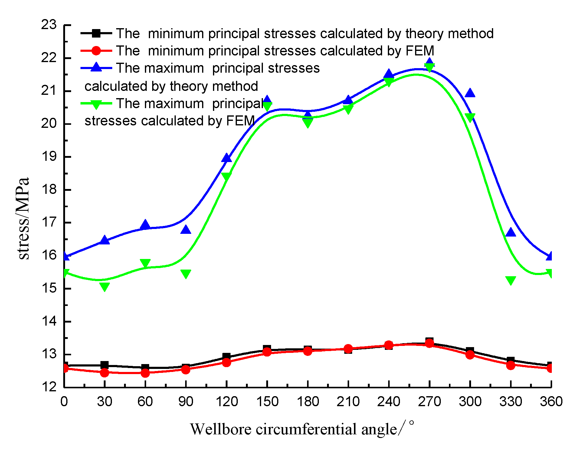
5.1. The Stress Field Comparative Analysis of Coal Seams Containing Multiple Cleats

In order to verify the accuracy of the coal seam stress field containing the multiple cleats analytical solution, the identical mechanical parameters are used, and the finite element model is established. Meanwhile, the principal stress map is obtained, as shown in Figure 7.
As shown in Figure 7, the existence of cleats makes the stress yielded around the coal bed in the wellbore extraordinarily complicated. According to the calculation consequence, the stress value of any point in the coal seam is vitally impacted by the cleats around. The following assumption is made, that is, the stress values are completely different among two points which are closed in the coal seam. To verify the accuracy of the analytical solution, the finite element results in the wellbore should be taken into account. Additionally, after calculation of the consequence at the counterpart position, the curve comparison is shown in Figure 8.
According to Figure 8, the maximum and minimum principal stresses calculated by the theory method are slightly larger than those calculated by the finite element method, and the relative error of those methods ranges from 0.64% to 9.16%. When the round angle ranges from 120° to 300°, the error is minimum. Based on these analyses, the proposed analytic model of the coal bed stress yield is reliable.

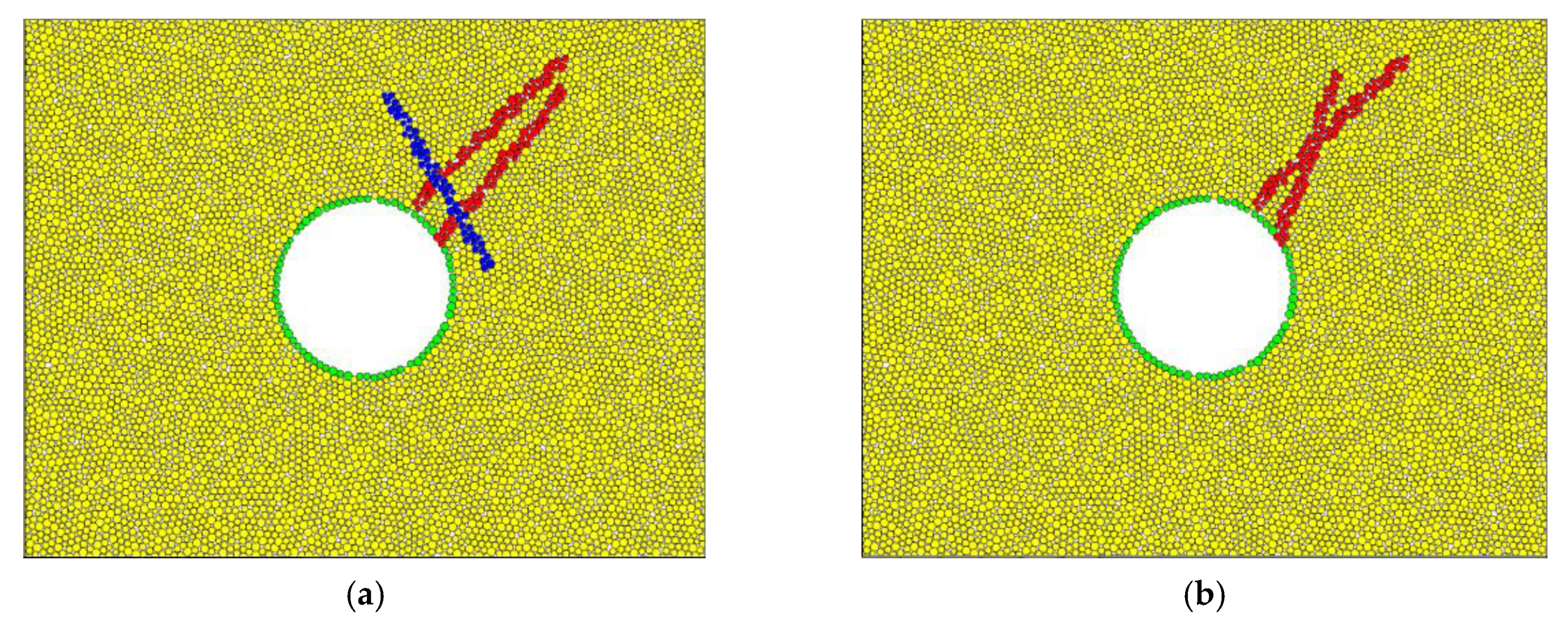
5.2. The Wellborn Stability Analysis of the Coal Seam

η SH , η EQ are defined as block strength coefficient and equilibrium slide coefficient, respectively, in this paper.
η SH =     τ oct a + b σ m + c σ m 2 ,
η EQ = F EQ S t l ,
If η SH 1 , the cleats present strength failure, but on the contrary, the cleats do not present strength failure. If η EQ 1 , the load balance of the block along the slide is broken, which means that the block begins sliding. Otherwise, the load balance of the block along its sliding is maintained. For the quadrilateral block, the only way to slide is by overcoming the strength in both sides along the sliding, and breaking the limit equilibrium in the side which is perpendicular to the sliding direction. So, there are three conditions required to judge the falling of the quadrilateral block. For the triquetrous block, the only way to slide is in overcoming the strength fracture on one side and breaking the limit equilibrium on the other side. Therefore, there are two conditions required to judge the falling of the triquetrous block.
In order to verify the accuracy of the analytical model, the numerical model is established by PFC software. The boundary condition (B.C.) of the numerical model is the same as that of the analytical model. The PFC numerical model is presented in Figure 9, and the red lines represent the face cleats, while the blue lines represent the butt cleats.
As seen from Figure 10, the PFC has calculated the sliding result of the block around the wellbore. The calculated result shows that the sliding coefficients of the analytical model prediction are listed as follows: the quadrilateral block, η SH 1 = 1.58 , η SH 2 = 3.31 , η EQ = 69.79 ; the triquetrous block, η SH = 2.49 , η EQ = 1.43 . Since all sliding coefficients are greater than 1, it indicates that the block will fall off. The prediction made by the discrete element method is in accord with the theoretical prediction. To further verify the accuracy of the analytical model, the minimum drilling fluid pressure of maintaining the stability of the wellbore will be calculated spontaneously by the analytical model and the discrete element model. From the results, for the quadrilateral block, the minimum drilling fluid pressure by the analytical mode is 9.4 MPa, and that by the discrete element model is 9.7 MPa and the gap is 3.19%; for the triquetrous block, the minimum drilling fluid pressure by the analytical model is 11.1 MPa, and that by the discrete element is 11.5 MPa, and the gap is 2.68%. Those results indicate that the analytical model and the discrete element model keep highly identical.

5.3. The Effect Factor Analysis

The stability of the coal seam wellbore is impacted greatly by the geometry and the position of the block. Therefore, this paper focuses on discussing how the face cleat spacing, the butt cleat spacing, the cleat length, the cleat inclination angle and the block geometric position have an effect upon the strength sliding coefficient and the equilibrium slip coefficient of the quadrilateral block and the triquetrous block. The calculation parameters and the analysis parameters can be referred to Figure 6.

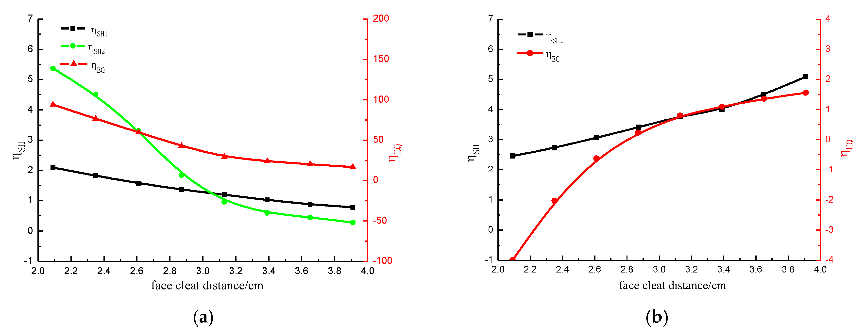
5.3.1. Face Cleat Spacing

In order to analyze the influence of the face cleat spacing for block sliding coefficient, the face cleat spacing between SL1 and SL2 is modified, keeping the other parameters invariant. The face cleat spacing ranges from 2.09 cm to 3.19 cm.
According to Figure 11, the addition of the face cleat distance will cause the decrease of the strength coefficient and equilibrium slip coefficient of the quadrilateral block, and the decrease of η SH 2 is greater than η SH 1 . When the distance is above 3.13 cm, the quadrilateral block stops falling off. On the contrary, the addition of the face cleat distance will cause the increase of the strength coefficient and the equilibrium slip coefficient of the triangular block, and the increase of η SH 2 is greater than that of η SH 1 . When the distance is above 2.87 cm, the triangular block starts to drop. The increase of the face cleat distance decreases the interference among the cleats. Additionally, it reduces the stresses of the lines AB and CD on the face cleats, and it causes the reduction of the strength slip coefficient. The difference of the direction and the length of the face cleats SL1 and SL2 are both the reason why the ranges of the discount are different between η SH 2 and η SH 1 . The increase of the face cleat distance causes the addition of the resistance to the triquetrous block sliding, and it reduces the un-equilibrium force in blocks, so the equilibrium slip coefficient decreases. For the triquetrous block, the shape becomes blunt and wide from a cuspidal, and the face cleat distance becomes narrow. Meanwhile, the angle of cleat SL4 decreases. Based on Equations (4)–(6), with the increase of shearing stress and tensile stress on the cleat SL4, the stresses on cleats AE, DE, the strength coefficient and the equilibrium slip coefficient, all increase.

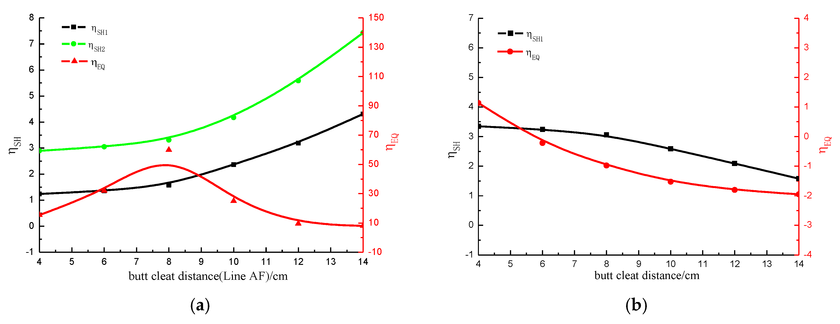
5.3.2. Butt Cleat Distance

In order to analyze how the butt cleat distance makes an impact on the block slip coefficient, the length of line AF is modified, keeping other factors invariant. The length of the line AF ranges from 4 cm to 14 cm.
According to Figure 12, with the increase of the butt cleat distance, the strength slip coefficient of the quadrilateral block increases, and the equilibrium slip coefficient of the quadrilateral block climbs up and then declines. But for the triquetrous block, the strength slip coefficient and the equilibrium slip coefficient decline. When the butt cleat distance is longer than 5 cm, the triquetrous block stops falling off. The reason is that under the local coordinate system of cleat SL3, the dimensionless radius among the midpoints of cleats AB and CD increases as the addition of the butt cleat distance. In addition, this causes the increase of the stress on cleats AB and CD, and at the same time, it affects the increase of the strength slip coefficient. It is hard to conclude the change law of the equilibrium slip coefficient, because the change of the butt cleat distance causes the stress changes on all the sides of the quadrilateral block. Therefore, the calculation is required to define these values. Because of the addition of the butt cleat distance, the body areas of the quadrilateral block and the triquetrous block increase, as well as the angle of cleat SL4. By Equations (4) and (5), we can know that it causes the decline of the shearing stresses and the tensile stresses on cleat SL4, as well as stresses on cleats AE and DE. As a result, the strength coefficient and equilibrium slip coefficient decline.

5.3.3. Cleat Length

Keeping other parameters invariant, we change cleat SL1 length and analyze the effect of the cleat length on the sliding coefficient of the block. SL1 ranges from 15 cm to 24 cm.
From Figure 13, it can be seen that the increase in the length of the cleat SL1 reduces the strength and equilibrium sliding coefficient. When the length of the cleat SL1 is greater than 21 cm, the quadrilateral block stops falling off, and the triquetrous block never falls off. The increase in the length of the cleat reduces the dimensionless radius of the midpoints of the cleat, thereby reducing the stress of the midpoints of the cleat, so the strength slip coefficient decreases. However, the internal pressure of the well wall has not changed. From the limit equilibrium equation, it is known that the decrease of the block slide force is larger than that of the resistant force, so the uneven force of the block decreases and then the equilibrium slip coefficient decreases.

5.3.4. Cleat Inclination

Keeping other parameters invariant, we change the inclination α S L 2 of the cleat SL2 and analyze the effect of the cleat inclination on the sliding coefficient of the block. Inclination α S L 2 ranges from 15° to 21°.
From Figure 14, it can be seen that with the increase of the inclination of the cleat, the strength slip coefficient of the quadrilateral block increases, the equilibrium slip coefficient decreases, and the strength and equilibrium slip coefficient of the triangular block increases. When α S L 2 20 , the triquetrous block changes start falling off. As α S L 2 increases, from Equations (4)–(6), it can be seen that the shear stress and the tensile stress on the cleat SL2 increase, and this results in an increase in the stress on the cleat AB and CD, and an increase in the strength slip coefficient of the quadrilateral block. Similarly, the strength slip coefficient of the triquetrous block increases as α S L 2 increases. The increase of α S L 2 shortens the length of the cleat BC, and reduces the block slide force, so the equilibrium slip coefficient of the quadrilateral block is reduced; and for the triquetrous block, the effect of the α S L 2 increase on the strength and equilibrium slip coefficient is the same as the increase in the distance between face cleats (see Section 5.3.1).

5.3.5. Block Geometric Position

Keeping other parameters invariant, we change α 1 and analyze the effect of the block geometry position on the strength and equilibrium slip coefficient. α 1 ranges from 0° to 180°.
From Figure 15a, we can see that with the increase of α 1 , the strength slip coefficient and the equilibrium slip coefficient of the quadrilateral block are approximately sinusoidal changes. When α 1 changes from 30° to 120°, the quadrilateral block starts falling off. From Figure 15b, we can also observe that with the increase of α 1 , the equilibrium slip coefficient of the triquetrous block is approximately sinusoidal, but the strength slip coefficient is undulating. When α 1 changes from −20° to 10°, and from 60° to 120°, the triquetrous block starts falling off. The change of α 1 causes the change of the cleat angle around the block, which causes the change in the induced stress field and at last causes a fluctuation in the strength and equilibrium slip coefficient.

6. Discussion

This paper presents a novel stress field analytical model of the wellbore coal rock in the broken coal seam. This analytical model considers the influence of the cleat filler, and by simplifying the cleat filler as the multiple rod structures (see Figure 2), we use the mechanics of materials and fracture mechanics to establish the induced stress field and the displacement field.
According to the limit equilibrium theory and the E.MG-C criterion, we further establish the stable analysis of the wellbore coal rock. The steps are: Firstly, we determine the motility of the block mainly including the shear plane parameters and the geometric parameters of the near-empty plane; secondly, we gain coal and rock cleat failure criterion; and lastly, we gain the block sliding direction. Taking vertical well HG61-4-X in the Qinshui Basin as an example, this paper uses a numerical method (see Figure 7 and Figure 9) to judge the validity of the analytical model.
This paper also analyzes the effect factors such as the face cleat spacing, the butt cleat spacing, the cleat length, the cleat inclination angle and the block geometric position. The results show that a quadrilateral block slides off easier than a triangular block under the same boundary condition; the bigger are the cleat spacing and cleat length, the lower is the risk at which blocks slide off, and the increasing cleat angle could cause blocks to slide off easily. Under the same boundary condition, it is closely related to the well round angle at which blocks slide off.
In addition, we merely consider the drilling fluid fluctuation in this paper. Thus, an improved and more general approach should be proposed in the future work to completely resolve the issue.

7. Conclusions

This paper establishes a stress field analytical model of the wellbore coal rock by considering the irregularity of the cleat distribution and the influence of the cleat filler. According to the limit equilibrium theory and the E.MG-C criterion, the wellbore stability model of the coal seam is established by determining, firstly, the motility of the block, secondly, the cleat failure criterion and thirdly, the block sliding direction. In order to judge the validity of the analytical model, this paper uses a numerical method to make a comparative analysis. At the same time, cleat affecting factors are studied in the paper.

Author Contributions

Conceptualization, X.Z.; methodology, X.Z.; software, Y.M.; validation, X.Z., J.W., and Y.M.; formal analysis, Y.M.; investigation, X.Z., J.W., and Y.M.; resources, Y.M.; data curation, J.W. and Y.M.; writing—original draft preparation, X.Z., J.W., and Y.M.; writing—review and editing, X.Z., J.W., and Y.M.; visualization, Y.M. and X.Z.; supervision, X.Z.; project administration, Y.M.; funding acquisition, X.Z. All authors have read and agreed to the published version of the manuscript.

Funding

This research is funded by the Natural Foundation of Shandong Province, grant number ZR2018BEE012 (Xinbo Zhao). Yue Mei also acknowledges the support from the Fundamental Research Funds for the CentralUniversities (Grant No. DUT19RC(3)017).

Conflicts of Interest

The authors declare no conflict of interest.

References

  1. Qin, Y.; Wu, J.G.; Shen, J.; Yang, Z.B.; Shen, Y.L.; Zhang, B. Frontier research of geological technology for coal measure gas joint-mining. J. China Coal Soc. 2018, 43, 1504–1516. [Google Scholar]
  2. Meng, S.P.; Liu, C.L.; Ji, Y.M. Geological conditions of coalbed methane and shale gas exploitation and their comparison analysis. J. China Coal Soc. 2013, 38, 728–737. [Google Scholar]
  3. Li, X.F.; Pu, Y.C.; Sun, C.Y.; Ren, W.N.; Li, Y.Y.; Zhang, Y.Q.; Li, J.; Zang, J.L.; Hu, A.M.; Wen, S.M.; et al. Recognition of absorption/desorption theory in coalbed methane reservoir and shale gas reservoir. Acta Pet. Sin. 2014, 35, 1113–1129. [Google Scholar]
  4. Ai, C.; Hu, C.; Zhang, Y.; Yu, L.; Li, Y.; Wang, F. Wellbore Stability Estimation Model of Horizontal Well in Cleat-Featured Coal Seam. In Proceedings of the SPE/EAGE European Unconventional Resources Conference and Exhibition, Vienna, Austria, 25–27 February 2014. [Google Scholar]
  5. Liang, D.C.; Po, X.L.; Xu, X.H. Particularity of coal collapse and drilling fluid countermeasure. J. Southwest Pet. Inst. 2002, 24, 28–31. [Google Scholar]
  6. Jianguo, Z.; Yuanfang, C.; Mingbo, S. Experimental study on sloughing mechanism of coal beds in Tarim Oilfield. Drill. Pet. Tech. 2000, 28, 21–23. [Google Scholar]
  7. AI-Ajmi, A.M.; Sultan Qaboos, U.; Zimmerman, R.W. Stability Analysis of Deviated Boreholes Using the Mogi-Coulomb Failure Criterion, With Applications to Some Oil and Gas Reservoirs. In Proceedings of the IADC/SPE Asia Pacific Drilling Technology Conference 2006—Meeting the Value Challenge: Performance, Deliverability and Cost, Bangkok, Thailand, 13–15 November 2006. [Google Scholar]
  8. Gallant, C.; Zhang, J.; Wolfe, C.A.; Freeman, J.; Al-Bazali, T.M.; Reese, M. Wellbore Stability Considerations for Drilling High-Angle Wells through Finely Laminated Shale: A Case Study from Terra Nova. In Proceedings of the SPE Annual Technical Conference and Exhibition, Anaheim, CA, USA, 11–14 November 2007. [Google Scholar]
  9. Jiang, Z.; Zhang, J.; Meng, Y.; Li, G. Analysis on the methods used to evaluate the wellbore stability of gas drilling. Nat. Gas Ind. 2007, 7, 68–70. [Google Scholar]
  10. Chunhua, G. Simulation of In-Situ Stress near Wellbore and Research on Wellbore Stability-Take Xujiahe Formation Gas Reservoir in Western Sichuan Depression as an Example. Ph.D. Thesis, Chengdu University of Technology, Chengdu, China, 2011. [Google Scholar]
  11. Zhang, Z.; Tang, C.A.; Li, L.C.; Ma, T.H. Numerical investigation on stability of wellbore during coal bed gas mining process. China Min. Mag. 2006, 15, 55–58. [Google Scholar]
  12. Qu, P.; Shen, R.; Fu, L.; Wang, Z. Time delay effect due to pore pressure changes and existence of cleats on borehole stability in coal seam. Int. J. Coal Geol. 2011, 85, 212–218. [Google Scholar] [CrossRef]
  13. Ping, Q.; Ruichen, S. Mechanism of wellbore stability and determination of drilling fluid density window in coalbed methane drilling. Nat. Gas Ind. 2010, 30, 64–68. [Google Scholar]
  14. Qu, P.; Shen, R.C.; Fu, L.; Zhang, X.L.; Yang, H.L. Application of the 3D discrete element method in the wellbore stability of coal-bed horizontal wells. Acta Pet. Sin. 2011, 32, 153–157. [Google Scholar]
  15. Mian, C.; Haifeng, Z.; Yan, J.; Yunhong, D.; Yonghui, W. A discontinuous medium mechanical model for the sidewall stability prediction of coal beds. Acta Pet. Sin. 2003, 34, 145–151. [Google Scholar]
  16. Zhu, X.; Liu, W.; Jiang, J. Research regarding coal-bed wellbore stability based on a discrete element model. Pet. Sci. 2014, 11, 526–531. [Google Scholar] [CrossRef] [Green Version]
  17. Ping, Q.; Ruichen, S.; Henglin, Y. Evaluation model of wellbore stability in coal seam. Acta Pet. Sin. 2006, 38, 835–842. [Google Scholar]
  18. Zhang, L.; Yan, X.; Yang, X.; Zhao, X. An analytic model of wellbore stability for coal drilling base on limit equilibrium method. J. China Coal Soc. 2016, 41, 909–916. [Google Scholar]
  19. Zhang, L.; Yan, X.; Yang, X.; Zhao, X. An analytical model of coal wellbore stability based on block limit equilibrium considering irregular distribution of cleats. Int. J. Coal Geol. 2015, 152, 147–158. [Google Scholar] [CrossRef]
  20. Jiancheng, J.; Hong, Z.; Qian, J.; Yan, W.; Miaofeng, Z.; Chen, C. Status and prospect: Study on the cleat system in coal reservoir. Nat. Gas Geosci. 2015, 26, 1621–1628. [Google Scholar]
  21. Close, J. Natural fracture in coal. AAPG Stud. Geol. 1993, 38, 119–132. [Google Scholar]
  22. Shengli, Z. Coal cleat and its significance in the coalbed methane exploration and development. Coal Geol. Explor. 1995, 23, 27–31. [Google Scholar]
  23. Xinbo, Z.; Xiujuan, Y.; Xiangyang, L.; Lisong, Z.; Xiangzhen, Y. Integrity analysis of high temperature and high pressure wellbores withthermo-structural coupling effects. Chin. J. Eng. 2016, 261, 13–20. [Google Scholar]
  24. Hongwen, L. Mechanics of Materials; Higher Education Press: Beijing, China, 2017. [Google Scholar]
  25. Shiyu, L.; Taiming, H.; Xiangchu, Y. Introduction of Rock Fracture Mechanics; University of Science and Technology of China Press: Hefei, China, 2010. [Google Scholar]
  26. Bing, H.; Hui, S.; Xianda, F.; Yu, L. Analysis and research on the whole stability of rock slope based on key block method. Eng. Technol. Appl. 2018, 24, 171–173. [Google Scholar]
  27. Mingming, Z.; Lixi, L.; Xiangjun, L. Impact analysis of different rock shear failure criteria towellbore collapse pressure. Chin. J. Rock Mech. Eng. 2017, 36, 3485–3491. [Google Scholar]
Figure 1. Model of coal wellbore stability.
Applsci 10 01169 g001
Figure 2. Mechanical model of the cleat filler.
Applsci 10 01169 g002
Figure 3. A normal load model with asymmetric distribution for cleats.
Applsci 10 01169 g003
Figure 4. A tangential load model with asymmetric distribution for cleats.
Applsci 10 01169 g004
Figure 5. Stress field near the cleat tip in plane problems.
Applsci 10 01169 g005
Figure 6. Calculation Model. α S L 1 , α S L 2 , α S L 3 are geometric angles of each cleat respectively; α 1 , α 2 are geometric position controlled angles of the block respectively; SL1, SL2, SL4 are face cleats, SL3 is butt cleat. (a) the quadrilateral block, (b) the triquetrous block.
Applsci 10 01169 g006
Figure 7. The main stress map of coal bed containing multiple cleats gained by field-emission microscopy (FEM). (a) The maximum principal stress map. (b) The minimum principal stress map.
Applsci 10 01169 g007
Figure 8. The main stress curves of the wellbore gained by FEM and the theory method.
Applsci 10 01169 g008
Figure 9. Discrete element method (DEM) model by the Particle Flow Code (PFC) software. (a) The quadrilateral block. (b) The triquetrous block.
Applsci 10 01169 g009
Figure 10. Slip map of the coal block near the wellbore by numerical simulation. (a) The quadrilateral block. (b) The triquetrous block.
Applsci 10 01169 g010
Figure 11. Influence of the face cleat distance on the slip coefficient distribution. (a) the quadrilateral block. (b) the triquetrous block.
Applsci 10 01169 g011
Figure 12. Influence of the butt cleat distance on slip coefficient distribution. (a) The quadrilateral block. (b) The triquetrous block.
Applsci 10 01169 g012
Figure 13. Influence of the cleat length on the slip coefficient distribution. (a) The quadrilateral block. (b) The triquetrous block.
Applsci 10 01169 g013
Figure 14. Influence of the cleat angle on the slip coefficient distribution. (a) The quadrilateral block. (b) The triquetrous block.
Applsci 10 01169 g014
Figure 15. Influence of the block geometric position on the slip coefficient distribution. (a) The quadrilateral block. (b) The triquetrous block.
Applsci 10 01169 g015
Table 1. Mechanic parameters of coal.
Coal and Rock Mechanics ParametersValue
Elastic modulus E/GPa10.15
Poisson ratio μ0.25
Biot coefficient αBiot0.76
Tensile strength St/MPa0.56
Elastic modulus of cleat filler Ef/GPa1.015
Face cleat tensile strength Stm/MPa0.274
Butt cleat tensile strength Std/MPa0.426
a1.613
b0.864
c−0.0014

