1. Introduction
Recently, a growing interest in deployable systems has been observed. Such systems have been constructed for use in space, as well as on Earth, where they can be applied in various fields of mechanical and civil engineering. Among the systems designed for space applications, the most popular are antennas, masts, and solar arrays. There are two main factors that need to be taken into account while creating such systems: a very compact and lightweight stowed form and the ability to automatically deploy in space [
1,
2]. In the present paper, the authors focus on deployable structures aimed at civil engineering applications, specifically columns. The design of such structures is focused on large shape and geometry changes with the simultaneous assurance of the stability, stiffness, and desired load carrying capacity of the deployed system.
Although the environment in which civil engineering structures are used does not resemble the one in space, deployable systems constructed for earthly use, such as columns considered in this paper, should also meet some of the criteria defined for astronautical applications. They should have small sizes in a folded form, and the deployment should be possible without or with the limited participation of humans. The weight of the structure is not as important here as in space; however, it can become a key factor from the point of view of transportation, mobility, possible application scenarios, and deployment. Having all these factors in mind, the authors searched for lightweight systems that could be used as deployable columns aimed at temporary applications.
There are in fact very few structural systems that meet the described criteria. One of the most popular are structures based on the scissor mechanism, which is relatively simple from the mechanical point of view. An interesting work was presented in [
3], where the author focused on showing a variety of shapes possible to obtain from the pantograph mechanisms. He presented spatial structures of pyramids, a tower, a bridge, a chair, an arch, plates, a vault, a dome, and even a boat. Another example is a mobile scissor bridge aimed at emergency use in remote disaster affected areas [
4]. Among other lightweight deployable systems, mechanisms based on air-filled elements deserve attention. In [
5], tensairity structures applied as deployable roofs and temporary bridges or buildings were presented. The work [
6] focused on deployable tensegrity systems with inflatable compression members. In [
7], inflatable roof systems were proposed. While discussing the deployment, the analysis of bridges under construction [
8] should also be mentioned. They are not directly related to deployable systems; however, studies of the behavior of bridges during the construction stages resemble in some aspects the analyses of the deployment scenarios.
An interesting group of lightweight structures suitable for deployment are tensegrity systems [
9,
10]. They can be defined as pin jointed systems that consist of cables (elements in tension) and struts (compressed members) and have infinitesimal mechanisms, which are balanced with self-stress states. Tensegrity systems have a very good stiffness-to-mass ratio and are prone to structural control through an adjustment of self-stress forces [
11]. The parameters of the unfolded structure, as well as its deployment can be controlled using only selected, so-called active members, which are a big advantage, as they reduce the number of actuators.
An example of a deployable tensegrity footbridge was presented in [
12]. Scientists from the Swiss Federal Institute of Technology in Lausanne constructed a prototype, which was formed by four pentagonal tensegrity modules with a total span of 16 m. In [
13], a deployable tensegrity mast was presented. Its structure was based on the system developed by Snelson [
14]—a mast constructed from overlapped regular simplex modules. Another structure of this type was proposed in [
15], where the authors presented an algorithm for the reconfiguration of a two-stage tensegrity mast. Another work [
16] explored possible deployment scenarios of tensegrity systems. They can be folded and unfolded in many ways: by modifying the lengths of struts, cables, or both, using a bundle or plane type folding.
In the present paper, the authors propose and analyze four lightweight deployable tensegrity columns. Although the structures are based on typical tensegrity modules and some of the already described connections are used, the results presented in this study are original from the point of view of civil engineering applications of these columns. To the best knowledge of the authors, there is no such thorough analysis in the literature that focuses on the comparison and assessment of tensegrity columns aimed at supporting lightweight structures. Most of the works that concern deployable tensegrity systems focus on the geometrical aspects in order to show the variety of possible applications of such structures or on the space applications, which cannot be directly applied to civil engineering problems.
The structures proposed in this work are aimed at civil engineering applications such as: supports for temporary structures (tents, big advertisement banners, temporary antenna masts), lightweight ceilings, large-scale tents, historic buildings, etc.; or as additional supports of structures affected by partial damage caused, for example, by fire.
The are various numerical and analytical methods that can be used for the analysis of lightweight deployable tensegrity systems. In [
12], the study of an active deployable tensegrity footbridge was presented. The author focused on the geometric study of the deployment, which was aimed at identifying the contact-free deployment-path space and the path with the minimum number of actuators required. The response of the structure was analyzed numerically using a dynamic relaxation algorithm. Another approach was proposed in [
15], where a reconfiguration study of multi-stage tensegrity systems was discussed. The authors used the infinitesimal mechanisms to generate a path of positions along which a multi-stage tensegrity can change its shape. They combined the force density method with a marching procedure and found a solution that was given by a set of differential equations that defined the kinematic constraints of the system.
In the present paper, the proposed tensegrity columns were analyzed using a method developed by the authors in [
17]. The method is based on the combination of two approaches: the finite element analysis (FEA) and the multibody dynamics (MBD) simulations. Due to the fact that this paper focuses on the preliminary numerical analysis of several structures and is aimed at finding the most appropriate solution for the assumed application, the proposed method has not been validated using any real models of the structures. Such a validation is planned as further steps of the research. However, the authors proved the reliability of the applied method by comparing the results obtained from MBD and FE simulations at various steps of the analysis.
2. In Search for the Best Solution
The aim of the present paper is to compare and assess several tensegrity columns and to find the best solution for the assumed application in civil engineering. In order to do so, various aspects need to be considered: the geometry of the columns, connections between the modules, the material of the structural elements, the type of analysis, etc. In this section, the authors discuss some of these aspects in order to justify the approach adopted in the paper.
There are many possible ways of creating tensegrity systems. They can be based on regular modules, which have been described in numerous works [
9,
10], or can be designed as entirely new systems using the form-finding process [
18]. The geometry of the columns proposed in this paper is based on regular tensegrity modules, which are connected either in initial nodes or by creating extra nodes (details are given in
Section 3).
Similar to the geometrical aspects, various materials can be used. It is not possible to indicate which materials are best for deployable tensegrity systems as this depends on their application. The materials used in space need to be as lightweight as possible, and they have to withstand severe environmental conditions [
1,
2]. In civil engineering applications, the materials depend on the scale and working environment. At the micro-scale (for example, engineering details or mechanical metamaterials), 3D printing can be adopted [
19]. At the medium- and macro-scale, both conventional materials (like steel) and novel structural materials (like for example the MoNiCamaterial described in [
20]) can be applied. Due to the fact that this study focuses on the columns used as additional supports of lightweight systems and no severe environmental conditions occur, the structures are made of steel: high strength stainless steel S460 (min. tensile strength 610 MPa, min. yield strength 460 MPa) is used for the cables, and high strength structural steel S355J2 (min. tensile strength 510 MPa, min. yield strength 355 MPa) is used for the struts.
Out of many possible approaches to the analysis of such structures [
12,
15,
21], the authors decided to use the one proposed in [
17], which combines the finite element method (FEM) and the multibody dynamics (MBD) simulations. Finite element modeling enables qualitative and quantitative analyses of the behavior of deformable structures with the defined boundary conditions and loading. It takes into account structural shape changes during the simulations. Multibody dynamics simulation, on the other hand, enables fast simulations of the systems consisting of rigid bodies with any translational or rotational displacements. It does not consider the deformations of structural members, since its equations of motion are built for rigid bodies, applied forces, and physical constraints. In this paper, the unfolded columns are analyzed using FEM, and the deployment itself is analyzed with the use of the MBD simulations. A multi-criteria approach of assessment is proposed, where various aspects are considered: geometrical parameters, deployment scenarios, mechanical behavior of the systems. The analyses are aimed at finding a lightweight tensegrity structure that has a good stiffness-to-mass ratio, maintains stability during the deployment, and can be controlled using as few active members as possible.
The presented analyses were carried out within the geometrically non-linear theory, which includes large deformations of the systems. The authors focused on the static calculations, as they are most important from the point of view of the considered application as a temporary support of the ceiling in the damaged building. In order to design a column for other applications mentioned in the Introduction, dynamic analyses should also be performed.
The approach adopted in this study should be considered as a first step of the design process of the proposed deployable columns. The whole process has to be divided into the following steps: numerical simulations described in this paper, which are aimed at indicating the best solutions within many possible ones; then the experimental tests at small- or medium-scale to analyze more thoroughly the selected structures; afterwards, a full scale model; and in the end, the application. Before the experimental tests are performed, the authors plan to carry out a parametric study, which will be aimed at identifying the parameters for which the columns are sensitive and those that do not affect the structural response in a way that would be significant from the point of view of deployability.
3. Description of the Columns
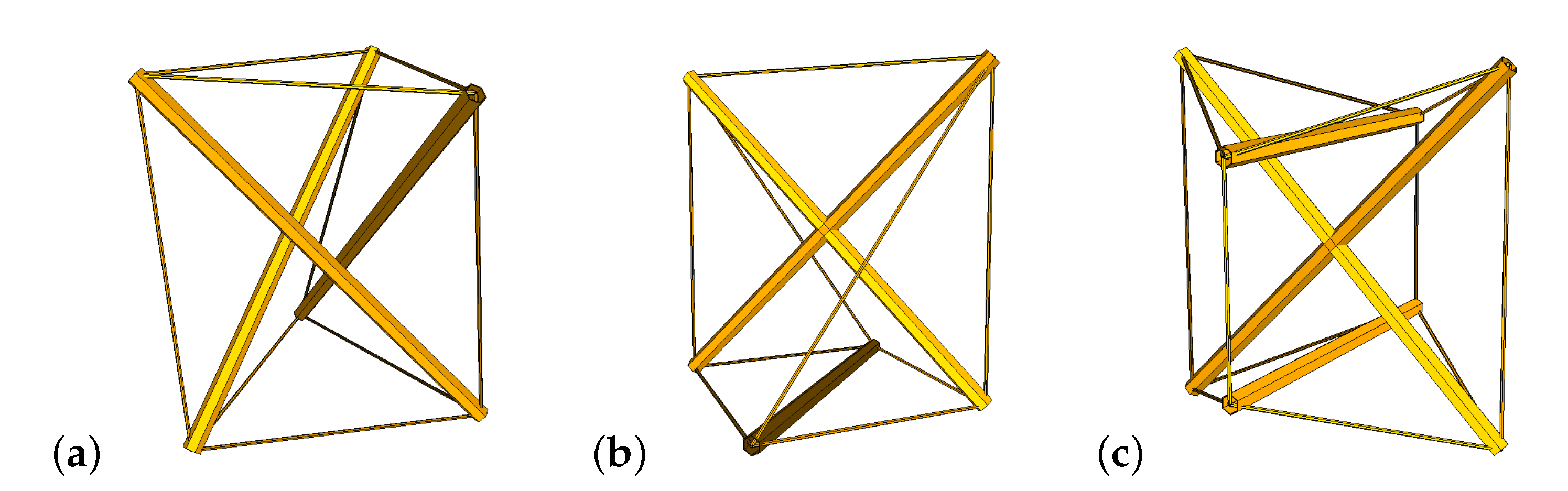
The tensegrity columns considered in this paper are based on three regular tensegrity modules: three-strut simplex (
Figure 1a), X-module (
Figure 1b), and expanded octahedron (
Figure 1c).
The properties of the modules are given in
Table 1. It can be noticed that the three-strut simplex and X-module are similar from the point of view of geometrical characteristics and mechanical features characterized by the number of infinitesimal mechanisms and the number of self-stress states that stabilize them. The expanded octahedron has more structural elements and more infinitesimal mechanisms; however, it was chosen because of its potentially high load carrying capacity.
There are three ways in which the columns can be constructed:
modular system—the structure is composed of regular tensegrity modules joined in nodes without any additional elements,
non-modular system—the structure is based on regular modules, but they are connected in such a way that they create a new tensegrity system,
modular system with extra cables—the structure is created similarly to the modular system, but some additional cables connecting adjacent modules are needed. Contrary to the module members, these extra cables are not prestressed.
Based on the described tensegrity modules and methods of constructing complex structural systems, four columns are proposed:
simplex (
Figure 2a)—a modular structure based on the three-strut simplex module,
overlapped simplex (
Figure 2b)—a non-modular structure based on the three-strut simplex module,
X (
Figure 2c)—a modular structure based on the X-module,
octahedron (
Figure 2d)—a modular structure with extra cables, based on the expanded octahedron module.
All columns consist of four modules and have a total height of 4 m. They can all be inscribed into a cuboid wit a square base of an edge of 1 m.
In the analyses, a uniform state of self-stress was adopted in all columns, which means that the prestressing forces are the same in each module of the given column. The level of self-stress is indicated by the factor , which is a multiplier of forces introduced to the structural members. There are three nodal supports in each column that eliminate the six degrees of freedom corresponding to the rigid body motion. The loading is applied to the nodes of the upper surface (the ones that support for example a ceiling plate) in the form of concentrated forces equal to: kN in the simplex and overlapped simplex columns and kN in the X and octahedron columns. The described forces correspond to a uniformly distributed surface load kN/m2 acting on the area of 25 m2. In addition, the self-weight of the structures is included. The values of external loading and prestressing forces were adopted so that the forces in the cables and struts were lower than 90% of the maximum load specified for the cables and struts. For structural members, catalog elements used in typical systems were used:
cables— mm made of steel S460 with a maximum load kN,
struts—hollow cross-section mm, wall thickness 2.6 mm, made of steel S355J2 with a maximum load kN.
3.1. Simplex Column
This is the most popular module when it comes to tensegrity structures. The basic equations for this module that describe the lengths of the cables and struts are given below in the final form in
Table 2. The authors found two scenarios of deployment that gave satisfactory results in terms of stability.
The first approach is to keep the defined tensegrity geometry by controlling all the cables lengths (see
Figure 3 and
Table 2). In this case, all the cables must be active during the whole deployment process.
The second approach was described in detail in [
17]. Modules are initially laying on the ground and are prestressed individually. Afterwards, the column is deployed module-after-module using additional cables that guide the proper joints of adhering sections to meet at the end of the process.
3.2. Overlapped Simplex Column
In this case, the approach is similar to the simplex column with differences resulting from the characteristic features of this structure.
The first approach is to keep the defined tensegrity geometry by controlling all the cable lengths. The basic equations for this module that describe the lengths of the cables and struts are given below in the final form in
Table 3 (compare the designations with
Figure 4). The equations are calculated for the rotation angle between the bases
, the modules’ rotation angle
, and the dimensionless offset
; where
h is the height of a single three-strut module and
m is a physical offset value between the modules. In this case, all the cables must be active during the whole deployment process.
The second deployment scenario is partially analogous to the second scenario of the simplex column. Initially, the structure is bundled, then it is stretched on the ground. Afterwards, active cables are shortened to introduce the prestress, and horizontal deployment starts. Then, the lowest base is set on the ground during the column rising.
3.3. X Column
The authors analyzed three possibilities of deployment for this column that seemed to be most natural.
The basic equations that describe the lengths of the cables and struts in this module are given below in the final form in
Table 4.
The first approach is to control the height of the structure by erecting or flattening single modules according to the formulas provided in
Table 4 (compare the designations with
Figure 5). The biggest disadvantage is the necessity to control all the cable lengths. On the other hand, this method maximizes the space savings for storing. Just like in the previous approach, here, applying elastic elements in parallel with the cables would be a way to keep the layout of the structure during the whole process and prevent the entanglement of cables. This would result in decreasing the amount of active cables.
Another approach is to obtain a flat structure that can be packaged either as a bundle or a plane. It can be achieved by elongating and shortening pairs of base cables to have a rotation of the neighboring modules. This approach is applicable only by assuming minimum global stiffness during the deployment, i.e., by applying elastic elements in parallel with the cables that would keep the layout of the structure during the whole process and prevent the entanglement of cables. This scheme was not analyzed further in this paper.
The second approach is to rotate the modules along the rotation axes between them. Those axes are stabilized by cables with no self-stress, and only these cables are used for the deployment. Single modules stay prestressed during the whole process and keep the predefined self-stress values all the time.
The third scheme makes use of elastic elements to stabilize the structure instead of active cables. The base cables are loosened as a function of the vertical cables’ shortening. The diagonal cables’ lengths stay constant so there is a need to stabilize the structure with elastic elements. Single modules stay prestressed during the whole process.
3.4. Octahedron Column
In this case, the authors found two deployment strategies that seemed to be promising in real applications.
The first approach is similar to other columns—manipulation of all cables to sustain the geometry of the tensegrity using the formulas given in
Table 5 (compare the designations with
Figure 6). In this module, in comparison to the X-module, the
r parameter must be split into
and
to describe its movement. In order to undeploy most efficiently, the
m parameter must change at some point to allow the full flattening of the structure.
The second approach is to relax the lower base cables of each module to allow controllable collapsing or rising of the structure. The movement can be of two kinds: axial (scissors-like movement of the diagonal struts) or folding (the diagonal struts rotate along with horizontal struts movement (parallel, in opposite directions). To define how the structure would fold in reality (this is not the case during the deployment), the application of elastic elements is a must to center the movement or to force the desired folding pattern.
4. Methods
This article is based on computer simulations to qualitatively and quantitatively compare four tensegrity columns. All the models were built in the same manner.
The FE analyses were carried out using SOFiSTiK software (SOFiSTiK AG, Germany, Version 12.01-27, Copyright 1996-2011, Licence: Faculty of Civil Engineering WUT). FEM [
22,
23] was used to statically analyze the final configurations of the structures—to find forces in the structural members and deflections of the columns, determine the load carrying capacity, etc. The calculations included self-stress and were based on the geometrically non-linear theory [
24]. Self-equilibrated sets of forces were determined using the spectral analysis of stiffness matrices. The mesh in the analysis was natural and suitable for pin joined structures. The accuracy of the FEM model for geometrical nonlinear problems was validated and confirmed for tensegrity structures in previous papers by the authors [
11,
25]. The material properties in FE models correspond to the parameters specified in
Section 3.
The MBD analyses were carried out using MSC Adams software (MSC Software Adams View, Version: Adams 2019.2, Build: 2019.2.0-CL661333 on Jun 19, 2019, Address: 4675 MacArthur Court, Newport Beach, CA 92660). The detailed description of the model building method can be found in [
17]. The movement during the deployment was defined as
, so there was a constant velocity of the chosen active cables, and all the other active cables lengths were calculated according to
Table 2,
Table 3,
Table 4 and
Table 5. The choice of the constant-velocity cables showed no substantial effect on the global behavior of the structure during the preliminary model verification. The following preliminary assumptions were made for the simulations:
The self-stress was calculated a priori for the defined height m. This means that during the deployment, the self-stress values do not meet tensegrity equilibrium, and the structure is not a real tensegrity system.
The joints are assumed to be ball-and-socket joints working without friction. Since in this case, the friction would act as a damper for velocity changes, it is assumed that the worst case scenario is simulated, and the structure eigen-properties must assure stability during the deployment.
The cables are modeled as springs with rigidity, which corresponds to the steel cable rigidity.
Due to the fact that the cables consist of a cable part and a spring part connected in series, it is not possible to have a zero length in the simulations, and in some cases, this leads to the impossibility of achieving maximal compactness for storing.
The collisions between the struts are not analyzed assuming shaping the target structure in such a way to prevent this phenomenon. For instance, this can be achieved by doubling the struts so one goes into the other one or, in the case of the joints, by applying already developed solutions (e.g., as described in [
13]).
There are no additional supports (e.g., guides) assumed to help sustain the shape during the deployment.
The method applied in this paper was validated by comparing the results obtained from MBD and FE simulations at various steps of the analysis. Initial self-stress values were applied in the Adams models; afterwards, the simulations were started, and the values of the internal forces in the structural elements were registered. Afterwards, three configurations of each structure were chosen, for which the models in SOFiSTiK were built, and these configurations were analyzed statically using FEM. In this way, the self-stress states were compared. The results obtained from both approaches were consistent, which proves the reliability of the proposed method.
5. Results and Discussion
The results are synthesized in
Table 6. They are divided into four main groups corresponding to the modules used. These groups are divided with the “/” sign in terms of the analyzed deployment scheme. The most desired values of each parameter are indicated in a box.
The first four parameters describe the basic properties of the columns.
The next three parameters are given with certain approximation because it is not possible to give exact values as the actual joints were not designed. The volume of the package describes the amount of space that the undeployed structure occupies when it is stored without considering cables’ volume. The compression ratio is the undeployed to deployed volume ratio. The space for deployment gives information on how much area is needed for the deployment process.
The column layout shall be understood as follows: modular—the structure is composed of regular tensegrity modules joined in nodes without any additional elements; non-modular—the structure is based on regular modules, but they are connected in such a way that they create a new tensegrity system; extra cables—like modular, but additional cables without prestress are needed. The package type defines in which form the structure can be stored. The next two parameters are straightforward. Sensitivity to external loads shall be interpreted as sensitivity to the additional forces (not the main load) acting in a vertical (e.g., gravity) or horizontal (e.g., wind) direction during the deployment. The amount of active cables tells how many cables must change their length in order to control the deployment. The amount of actuators indicates how many mechanical devices are needed to control active cables or groups of cables.
The tensegrity class is defined according to [
18] and should be understood as follows: a tensegrity of class
n is a structure in which at most
n struts are connected to any node. The number of infinitesimal mechanisms and the number of self-stress states characterize the mechanical behavior of tensegrity systems.
The mass of the structure is the sum of the cable and strut masses excluding the mass of the joints. The density of the structure is calculated as the volume of a cuboid that is circumscribed on the deployed structure divided by the mass of the structure. The LCC parameter is a dimensionless load carrying capacity and should be understood as the ratio of the load carrying capacity of the column to its weight. The load carrying capacity is the maximum external load that can be applied before a failure occurs. The failure shall be understood as reaching the maximum load specified for structural members in
Section 3 or the loss of equilibrium of the whole system. The pre-extension of the structure is a parameter that says how much higher the structure should be in the initial state in order to obtain the desired height
m under the applied load.
The results given in
Table 6 are discussed for each column separately. The final remarks and summary for all the columns are given in the Conclusions. As was stated in the methods’ description, the figures representing the beginning of the deployment are not always in a real initial state due to the modeling method used. In reality, they can be flattened more.
Apart from the results presented in
Table 6, two additional parameters were considered in the analysis: maximum forces in structural members (
Figure 7) and deflection of the columns (
Figure 8).
Figure 7 and
Figure 8 show how these parameters depend on the self-stress level
. It can be noticed that the octahedron column is very stiff as its deflection is almost constant within the considered range of prestressing forces. The least stiff is the X column; however, the simplex column is more prone to structural control than the X as its deflection decreases most rapidly with an increase of
. The biggest increase of maximum tension forces in cables and the decrease of the minimum compression forces in struts are observed in the octahedron column, whereas the X and overlapped simplex columns are the least sensitive to self-stress in this regard.
5.1. Simplex Column
In the first deployment scenario, there are 27 cables, and all of them are active to change the height of the structure, keeping the tensegrity form all the time. The number of actuators is 16, which is less than the number of active cables because cables that have the same function of length can share the actuator. In this case, it is assumed that diagonal cables are grouped into pairs (one actuator per pair), and two out of three base cables are also grouped (one must be controlled separately due to their odd number). The column is planar in a stored form; it might be bundled after full relaxation of the cables, but this would cause major cable entanglement and trouble during the following deployment. Since there are 16 actuators that must be operated at the same time, it is assumed that this cannot be done by hand, but one person can operate the synchronized powered actuators. The column is prestressed all the time so it is assumed to be insensitive to additional forces (they change the deflection, but do not destabilize the structure).
In the second deployment scenario, there are more cables, but fewer actuators. In this approach, the separate neighboring simplex modules have one common cable between the bases, which coincides with the axis of rotation. Other base cables are separated, and the third joint is also split. During the deployment, this split joint is reconnected by an additional active cable. This is valid for three intermodular bases and the lowest base that touches the ground. Initially, the individual modules must be prestressed using at least one active cable. That gives a total of eight active cables. The natural storing form for this layout is a bundle. The prestressing and column erection can be performed by hand and by one person because the active cables can be adjusted one-by-one. The structure is still stable vertical-wise, but it can be susceptible to horizontal forces (depending on the direction).
In the first scheme, the structure can be deployed directly on the ground since all the supports are in plane. In the second scheme, the structure should rather be placed on a platform that assures proper support for the bottom base nodes—especially for the one that is displaced during rising of the column.
In
Figure 9, both deployment scenarios are presented at the beginning of the deployment. A vast difference in space demand can be observed.
What can be seen in
Figure 9a is a structure in its folded form, ready to be deployed. In reality, it can be even flatter (here, it is higher due to the computer model limitations). In
Figure 9b, the structure is preset for deployment i.e., it is stretched over the area and ready for the self-stress to be applied.
5.2. Overlapped Simplex Column
In the first deployment scenario, there are 54 cables, and all of them are active to change the height of the structure, keeping the tensegrity form all the time. The number of actuators is 23, which is less than the number of active cables because cables that have the same function of length can share the actuator. The grouping is analogous to the simplex column (6 actuators for diagonal module cables, 12 actuators for diagonal intermodular cables, and 13 cables for base cables). The column is planar in the stored form with the same remark on bundling as in the simplex column case. Since there are 23 actuators that must be operated at the same time, it is assumed that erecting cannot be done by hand, but one person can operate the synchronized powered actuators. The column is prestressed all the time, so it is assumed to be insensitive to the additional forces.
In the second deployment scenario, there is one cable more, but with less actuators used. This additional cable controls one of the joints (on the lowest base) that initially does not touch the ground. The deployment is analogous to the second deployment scheme of the simplex column. The deployment can be realized by controlling the aforementioned base cable and three diagonal intermodular cables (the structure is flexible enough to be set between two parallel planes during the rotation; see
Figure 10). Initially, the structure must be prestressed/shaped from the bundle form using a maximum of 30 module and intermodular diagonal active cables (this is the worst case scenario, but in reality, it might be less; laboratory tests must be performed in the future), which gives 33 active cables in total. The intermodular diagonal active cables can be controlled in pairs, which gives 21 actuators at the end. The prestressing and column erection can be performed by hand and by one person because the active cables can be adjusted one-by-one. The natural storing form for this layout is a bundle. The structure is still stable vertical-wise, but it can be susceptible to horizontal forces (depending on the direction).
Here, the supports shall be assured analogously to the simplex column described earlier.
In
Figure 10, both deployment scenarios are presented at the beginning of the deployment. For the second scenario also, the selected frames from the deployment are presented.
In
Figure 10a, a structure is in its folded form, ready to be deployed. In reality, it can be even flatter (here, it is higher due to the computer model limitations). In
Figure 10b, the structure is preset for deployment, i.e., it is stretched over the area and ready for the self-stress application. In
Figure 10c, the structure is deployed using an additional cable that connects one of the base nodes with the ground. On the left, there is a random middle time frame presented; on the right, there is a situation presented where the structure deforms to be placed under a flat surface (4 m above the ground). Afterwards, the self-stress will be applied.
5.3. X Column
In the first deployment scenario, there are 36 cables, and all of them are active to change the height of the structure, keeping the tensegrity form all the time. The amounts of active cables and actuators are calculated as previously: diagonal, as well as bases cables are connected in pairs (which gives 16 actuators in total). The column is planar in the stored form with the same remark on bundling as in the simplex column case. Due to the amount of actuators, it is assumed that the deployment cannot be done by hand, but one person can operate the synchronized powered actuators. The column is prestressed all the time, so it is assumed to be insensitive to the additional forces.
In the second deployment scenario, there are only seven active cables (the diagonal ones) that can be grouped into pairs in order to apply fewer actuators (four). The column erection can be performed by hand and by one person because the active cables can be adjusted one-by-one. The structure is still stable vertical-wise, but it can be susceptible to horizontal forces (depending on the direction), which can be canceled out by adding stabilization by seven other diagonal cables.
In the third deployment scenario, there are 22 active cables (the bases and the vertical ones between the “X” struts). The base cables can be grouped into pairs in order to apply fewer actuators (16 in total). Due to the amount of actuators, it is assumed that the deployment cannot be done buy hand, but one person can operate the synchronized powered actuators. The use of elastic elements eliminates eight additional actuators, and the structure remains stable enough.
In all the schemes, the structure should be placed on a platform that assures proper support for the bottom base nodes; two out of four nodes are connected to the supports via cables.
In
Figure 11, all the deployment scenarios are presented during different time frames.
In
Figure 11a, a structure is in its folded form, ready to be deployed. In reality, it can be even flatter (here, it is higher due to the computer model limitations). In
Figure 11b, the structure is folded and ready to be deployed. The self-stress is applied, and deployment can be initiated by active cables that will have zero self-stress once the column is fully erected. In this model, struts penetrate each other, but in reality, they can lie parallel to one another by designing proper joints. In
Figure 11c, the deployed and folded (here, it is higher due to computer model limitations) structure with additional elastic elements is presented. In reality, it is expected that this layout will fold just like the first scenario.
5.4. Octahedron Column
In the first deployment scenario, there are 56 cables, and all of them are active to change the height of the structure, keeping the tensegrity form all the time. The number of actuators is 28. The grouping scheme is analogous to the simplex column; it is also assumed that the cables connecting horizontal struts are joined in pairs. The difference in length must be compensated by the actuators’ movement, which would have to be split with a defined ratio, which can be done since the stroke function is linear. The column is planar in the stored form with the same remark on bundling as in the simplex column case. Since there are 23 actuators that must be operated at the same time, it is assumed that erecting cannot be done by hand, but one person can operate the synchronized powered actuators. The column is prestressed all the time, so it is assumed to be insensitive to the additional forces.
In the second deployment scenario, there are 16 active cables. The number of actuators is eight. It is assumed that the base cables are connected in pairs. The column is planar in the stored form with the same remark on bundling as in the simplex column case. Since there are eight actuators that must be operated at the same time, it is assumed that erecting cannot be done by hand, but one person can operate the synchronized powered actuators. The structure is still stable vertical-wise, but it can be susceptible to horizontal forces (depending on the direction).
Here, the supports shall be assured analogously to the X column described earlier.
In
Figure 12, all the deployment scenarios are presented during different time frames.
In
Figure 12a, the structure is in its folded form, ready to be deployed. In reality, it can be much flatter (here, it is higher due to the computer model limitations). The case presented on the right illustrates the deployment pattern where single modules unfold.
6. Conclusions
The analyses presented in this study proved that it is possible to build a deployable supporting structure for civil engineering applications using a tensegrity system. The question was: Which of the analyzed columns is most appropriate for this task? As can be seen in the Results Section, there is no straight answer to this question. Depending on the specific application in which the column needs to be used, different systems can be indicated.
The simplex and overlapped simplex columns are the most popular in the literature because the basic simplex module is very plain, well described, and easy to connect. However, the authors proved that even though these two columns have the best compression ratio, they are rather complicated to control and are unstable during the deployment process. Moreover, the overlapped layout is not that simple to control due to the large amount of actuators. Therefore, the popular columns based on three-strut simplex patterns are not recommended as supports of civil engineering structures. They could be selected only in cases where the volume of the package is crucial, for example from the transportation point of view.
Analysis of the results presented in this paper leads to the conclusion that the most appropriate columns for the assumed application are X and octahedron columns. The X column in its second deployment scenario demands the least active cables and the least actuators. It is the lightest one and has a fair compression ratio due to the fact that it can be made entirely flat for storing. On the other hand, it demands the most space for deployment, so when this is an issue, the second best is the octahedron column, which demands the least space and is still reasonable to control. The X column is also most compliant, which can be advantageous when dynamic loads come into consideration. Alternatively, the octahedron column is the stiffest one. It has the highest load carrying capacity, so it is recommended for use in heavier structural systems or with bigger live loads.
Taking into account all the obtained results, the authors recommend using X columns as additional supports of temporary or lightweight structures (tents, temporary ceilings, etc.) and octahedron columns as supports of heavier structures where the high load carrying capacity plays an important role.
This research, consisting of broad FEM and MBD analyses, provided all the necessary data for building small- and then medium-scale real models for laboratory tests. At this stage of the research, the authors validated the applied method numerically, by comparing self-stress states at various steps of the analysis. When the real models of the structures are constructed, a further validation is planned using the data from the laboratory tests. After this step, the authors aim at building a full-scale object. This data may also be used as a starting point for research in other fields of science like robotics or mechatronics.


