Article

Smart Heating and Cooling Heat Pump System by Standing Column Well and Cross-Mixing Balancing Well Heat Exchangers

1
Department of Mechanical and Shipbuilding Convergence Engineering, Pukyong National University, Busan 48547, Korea
2
Department of Architecture Engineering, Songwon University, Gwangju 61756, Korea
*
Author to whom correspondence should be addressed.
Appl. Sci. 2020, 10(21), 7643; https://doi.org/10.3390/app10217643
Submission received: 25 September 2020 / Revised: 20 October 2020 / Accepted: 28 October 2020 / Published: 29 October 2020
(This article belongs to the Special Issue New Trends in Enhanced, Hybrid and Integrated Geothermal Systems)

Abstract

:
Standing column well (SCW) geothermal heat exchanger permits a bleeding discharge of less than 20% in the event of a maximum load, which is an inappropriate method of using underground water. In this study, the existing operational method of two adjacent SCW geothermal heat exchangers, each with a single well, was modified. This technology aims to improve the coefficient of performance (COP) of the geothermal system by fundamentally preventing underground water discharge and maintaining a constant temperature of the underground heat exchanger. To curb the bleed water discharge, two balancing wells of cross-mixing methods were employed. The result of the cooling and heating operations with the existing SCW heat exchange system and the balancing well cross-combined heat exchange system showed that the measured COP increases by 23% and 12% during the cooling and heating operations, respectively. When operating with a balanced well cross-mixed heat exchange system, the initial temperature of the underground was constant with a small standard deviation of 0.08–0.12 °C.

1. Introduction

Technology using the underground environment in architecture has been applied in various forms from an energy-efficient perspective, such as in the composition of space and elements for responding to climate change. In particular, a ground source heat pump, which uses a constant layer of geothermal heat and water temperatures (100–200 m underground) inside the basement of buildings, is widely used as a heating and cooling system for buildings [1].
The soil constituting the underground environment is a porous body formed by three phases of water, pore, and soil particles. Meanwhile, the water constituting the soil is further divided into soil water and groundwater. Among them, groundwater fills the gap in the inner rock of the earth and has fluidity due to gravitational action. The pluggable stratum containing this groundwater is called the aquifer [2]. An open geothermal heat pump system using underground water from the aquifer is expected to perform better as a heat exchange medium than an enclosed system through a direct heat exchange with heat sources. However, its performance is considerably affected by the groundwater quality and quality conditions, such as groundwater heat. Problems such as a drop in groundwater levels, depletion of groundwater, and a drop in temperature occur due to groundwater intake and injection. Therefore, a technology that can fully preserve the underground quality while ensuring stable system performance should be developed. Research on the development of optimal design methods for improving the performance of open geothermal systems or geological hydrological considerations of the ground, based on the use of systems, has been conducted in various fields. To develop an optimal design method for an open system, research on improving the existing geothermal system or analyzing the temperature profile and thermal behavior of the tube and soil according to system operation has been mainly conducted using numerical analysis models [3,4,5,6], and the underground water recovery and flow due to system introduction have been analyzed using numerical analysis models [7,8]. The effects of open geothermal heating and cooling system on the geochemical properties of groundwater and the repair and geology characteristics of aquifers, such as temperature and groundwater level, were actively determined [9,10]. Research has also been conducted on the proposed method of heat recovery or performance analysis by introducing an open geothermal system in certain areas where the geothermal energy potential is high, such as mines, and where large amounts of groundwater exist [11,12,13,14,15,16,17,18,19]. Clearly, research on the design method is actively conducted to improve the performance of open geothermal systems or on the mathematical considerations after the introduction of the system. However, few studies have developed design techniques that can maintain a long-term stable performance or continuous operation of the system.
Among the technologies using renewable energy sources, geothermal heat pump systems have better energy utilization efficiency than other heat source systems and provide stable heat sources throughout the year. In particular, the groundwater heat pump system, which utilizes groundwater in the aquifer, is expected to have a significantly higher performance than that of the enclosed geothermal heat pump system by performing direct heat exchange with groundwater. In addition, it can respond positively when a large-scale heating and cooling demand is required within a limited installation site, and economic feasibility can be ensured as the number of geothermal installations is lower than that of enclosed systems depending on the underground water and ground conditions. However, the open geothermal heat pump system is significantly affected by repair quality conditions, such as the size of the aquifer, groundwater quality, and the ground pitching factor. Hence, the operation of the system is restricted if the aquifer does not exist abundantly inside the soil or the groundwater quality and ground pitching factor conditions are unfavorable.
Therefore, the design and operational methods of the open geothermal heat pump system are being actively developed based on the ground repair geometrical conditions. In particular, Sciacovelli et al. [20] and Park et al. [21] conducted studies on open geothermal heat pump systems to review the conditions of water quality in soil according to the design factors. Russo and Civila [22] studied the optimal geothermal deployment plan for improving the performance of open geothermal systems. Kim et al. [23] conducted a study that improved the design method of open geothermal systems. Meanwhile, Bae et al. [24] conducted a study on the underground heat and groundwater movement in soil following the introduction of the system using simulation. Consequently, the underground water level rise of the infusion wells was confirmed if the ground pitching coefficient is unfavorable or if the water table is high. Another study [25] analyzed the effects of the groundwater level adjustment by simulating a multiple-static geothermal system connecting the inter-tube channels to prevent the occurrence of operation restriction due to the overflow of underground water in infusion wells due to the long-term operation of an open geothermal heat pump system. However, most of the studies performed thus far are based on numerical simulation and are still to be tested at the experimental stage.
Geothermal heat pump systems have been introduced and used in Korea since the early 2000s, and the supply and installation capacity has also increased every year. The geothermal heat pump system consists of a heat pump, which is responsible for the heating and cooling of buildings, and an underground heat exchanger, which absorbs heat from the ground and then releases it to the ground. Ground heat exchangers are used to maintain a constant ground temperature throughout the year, ensuring higher heat exchange efficiencies than those of air heat source heat exchangers. The table of compliance has not been established for standing column well (SCW)-type underground heat exchangers introduced in Korea; thus, there is an ambiguity in applying SCW-type underground heat exchangers to geothermal heat pump systems depending on regional characteristics (e.g., geology, groundwater volume, number of aquifer layers, and level of development), installation methods, and shape of heat exchangers. Kim et. al. [26] established the shape of the heat exchanger through the standardization of products, including the shape and construction of an SCW underground heat exchanger, while establishing a measurement method for the underground thermal conductivity of SCW underground heat exchangers to develop a standard for the design of the heat exchanger.
The effects of circulation water temperature, borehole heat resistance, and underground heat conductivity on various design and operational variables of SCW underground heat exchangers were studied. Among them, the bleed is reported to have the largest effect on the heat transfer enhancement of SCW underground heat exchangers [27]. Bleeding is a method of operation in which underground water extracted from a geothermal well enters the heat pump, exchanges heat, and then releases some underground water to the surface during the process of injecting it back into the same well. Bleed rate is the ratio of the amount of groundwater extracted from the geothermal well and the amount of groundwater released to the surface. Bleeding can also induce underground water that exists near the geothermal well from the underground into the well. The heat exchange capacity of SCW underground heat exchangers can be increased through bleeding in areas where underground water is abundant, and guidelines on support for renewable energy facilities of the Korea Energy Corporation allow bleeding rates of up to 20% for SCW underground heat-burning machines [28]. However, a high rate of bleed application can drain the surrounding groundwater to which a geothermal heat pump system is applied and can also cause heat pump failure due to the groundwater level falling below the pump. Currently, various underground heat exchangers using thermal response tests have been studied in Korea and internationally [29,30,31,32,33,34], and the energy equilibrium using thermal response test data has also been studied [27,35]. From the results of an analysis in [36], the temperature change of the underground heat exchanger circulation water tends to decrease as the bleed rate increases, and the underground thermal conductivity increases from 0% to 179% at a bleed rate of 0% to 30%, respectively. Meanwhile, when groundwater is introduced from the underside of the underground heat exchanger, the underground heat exchanger circulation water is mixed with groundwater from the bottom after exchanging heat with the ground; thus, the temperature change of the underground heat exchanger circulation water tends to rise initially over time. However, as the bleed rate increases, the rise tends to decelerate and remain constant if the bleed rate exceeds approximately 10%.
In this study, geothermal cooling and heating systems, possessing superior energy utilization efficiency, are used owing to a stable supply of heat sources throughout the year, compared to other heat source systems. In particular, an open geothermal system that uses underground water in the aquifer has been selected for its better performance than an enclosed geothermal system because of its direct heat exchange with rocks. However, bleeding should be performed to improve the forced discharge of groundwater to prevent the geothermal circulating water temperature rise. Meanwhile, for this new technology, a water level difference was formed through refill to use the bleed-discharged water without being discarded, and the thermal performance characteristics were evaluated by applying the balancing well-type underground heat exchanger operation technology to prevent blockage of the underground heat exchanger through cross-operation. The system performance coefficient was compared and analyzed according to the application of an underground heat exchanger by cross-mixing the existing standing column well (SCW) and the balancing well method.

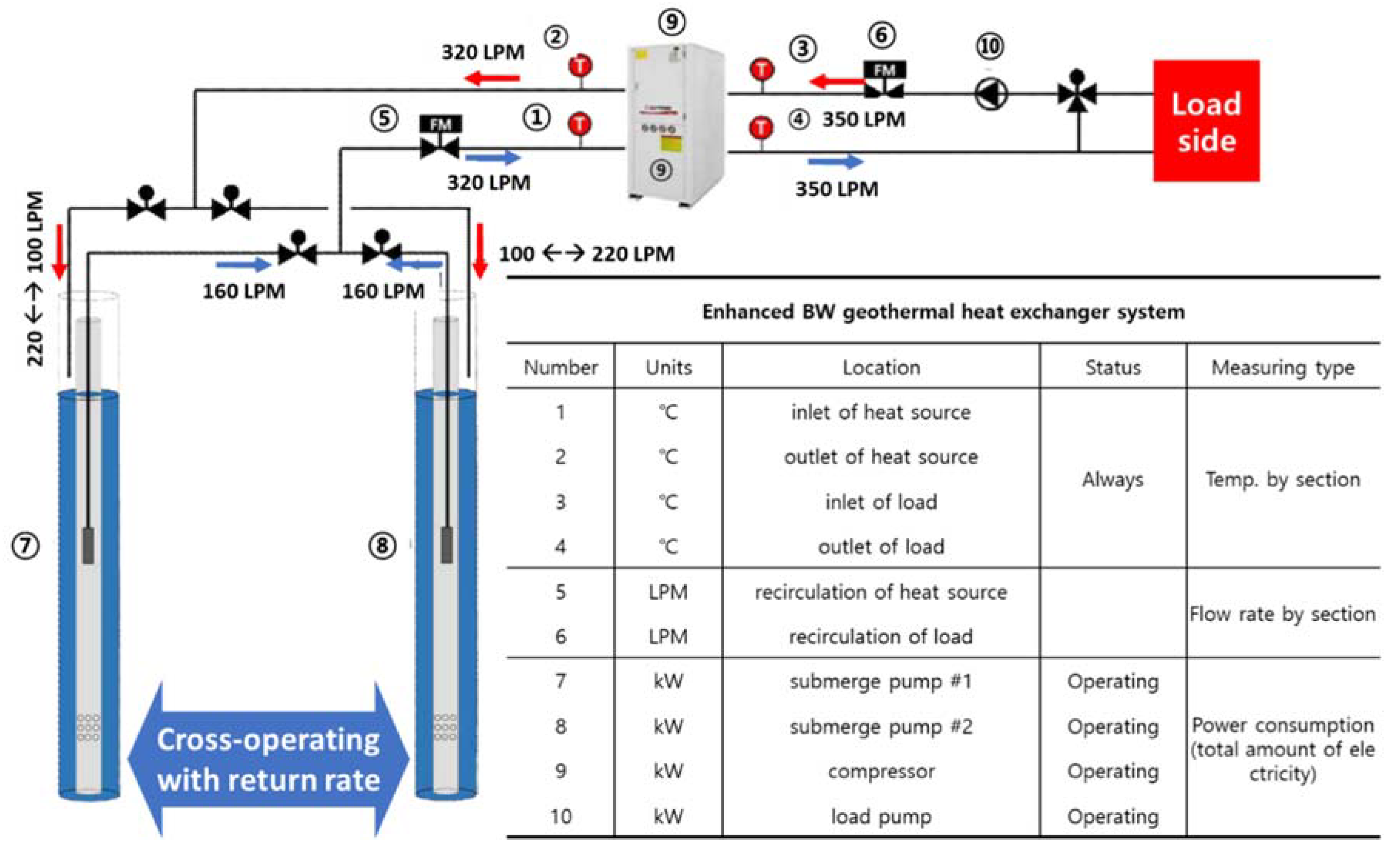
2. Experimental Methodology

Figure 1 shows a comparison test with the existing open underground heat exchanger and cooling and heating operation used to evaluate the energy efficiency and performance coefficient of the system suitable for on-site testing using the test method of the water-water geothermal source heat pump unit. An automatic cross-operating control system was used to maintain the optimal supply of heat sources for the existing SCW and for balancing well underground heat exchangers. The balancing well cross-mixed heat exchange geothermal heat pump system consisted of a geothermal source heat pump and underground heat exchanger and includes the cross-operation controller among the mechanical piping and circulation pump and system control system.
The test targets were a geothermal source heat pump for 30RT-level cooling and heating and two underground heat exchangers with a typical SCW system installed with a diameter of 10 in (0.254 m) and depth of 300 m. The SCW underground heat exchanger had a natural water level of 4.7 m and a maximum quantity of 350 tons/day. The distance between the two wells was approximately 12 m.
To verify that the experimental measurements were reasonable, as shown in Figure 1, a justifiable means of validation was required. The simplest expression of the heat balance equation is
q i n ˙ = m ˙ · C p · ( T o u t T i n )
where q i n ˙ (W) represents the measured heat input to the water heater elements and pumps; m ˙ (liter per minute, LPM) is the flow rate; Cp denotes the specific heat of water; and Tin and Tout represent the temperatures measured with a thermostat.
After applying all the calibration equations to the measurement devices, the heat transfer rate predicted by the right-hand side of Equation (1) can be compared to the measured power input (left hand side of Equation (1)). The numbers summarised in Table 1 are the average values over the length of each test, and they were used to compare the instrumentation uncertainties and total heat input error.
The uncertainties in the temperature measurement were ±0.01 °C for the probes and ±0.04 °C for the signal conditioner of the digital displays with the analog signal. The total uncertainty for the temperature measurements are expressed in quadratic form, as shown in Equation (2):
T = ( ± 0.01 ) in 2 + ( ± 0.04 ) in 2 + ( ± 0.01 ) out 2 + ( ± 0.04 ) out 2 ± 0.0825  
Considering that T for each test is approximately 5 °C, the uncertainty due to the temperature measurement becomes:
Error = ± 0.0825   5   × 100 % = ± 1.65 %
Using the highest error for the flowmeter taken from Table 2 of ± 2.03%, the total uncertainty in the heat balance equation was computed as:
Total   Error = ( ± 0.0165 ) 2 + ( ± 0.0203 ) 2 2.62 %
As shown in Figure 2, the balancing well cross-mixed heat exchanger system is characterized by different operation methods in the two SCW-type geothermal heat exchangers with 100% pumping from each geothermal heat exchanger, while the recovery quantity is different. In other words, the principle of generating a flow of groundwater in the underground aquifer was applied to generate a difference in the operation level of the two SCW geothermal heat exchangers. In this study, the experiment was conducted using the cross-operating condition supply and return of 80% and 120%, respectively, as depicted in Figure 2a. If the circulation water supplied simultaneously from both the ground heat exchangers is returned after the heat exchange, 120% of it is recovered to the ground heat exchanger (#1 zone), and 80% of the remaining circulation is recovered to the other ground heat exchanger (#2 zone) and the cross-operating mains, which are set to activate the aquifer by forming a difference in the groundwater level.
The system energy efficiency is calculated as the ratio of the resultant value of the production heat obtained by applying the liquid enthalpy test method of the heat source and load sides to the coefficient of performance (COP) of the system to compare it with the existing SCW geothermal system.
In the liquid enthalpy method, the temperature, flow rate, and electricity consumption of circulating water are recorded through the data logger at the entrance and exit of the heat exchanger on the heat source and the load side of the heat pump. The produced heat of the geothermal system is calculated using the following equations.
Where, total power consumption means the total consumption power used in the geothermal system. The COP of the actual geothermal system was calculated using Equations (5) and (6), and these results were configured to be calculated by the system [21,22].
Cooling mode:
tco = w f c p f ( t f 4 t f 3 ) t
Heating mode:
tho = w f c p f ( t f 3 t f 4 ) + t
where,
tco : Total cooling capacity of the heat pump (W)
tho : Total heating capacity of the heat pump (W)
t f 3 : Heat pump inlet temperature (°C) of circulating water on the source side
t f 4 : Heat pump outlet temperature (°C) of circulating water on the source side
c pf : Specific heat of heat source circulation water (J/(kg·K))
w f : Mass flow rate of circulating water on the heat source side (kg/s)
t : Total power Consumption (W)

3. Results and Investigations

3.1. Performance Evaluation under Cooling Operation

The experimental set-up stabilized after 30 min of test operation, and data were recorded once per day for five days, with each recording session lasting a continuous 6 h. Through this experiment, the initial underground temperature, temperatures at the entrance and exit of the geothermal circulation water, circulation flow rate, and the electricity used were recorded by the data logger. The results are presented in Figure 3 and Figure 4. The COP was calculated by using the data recorded and by applying Equation (1). The measured values of the power and COP of the two systems are listed in Table 3 and Table 4.
The plots of Figure 3a showed that the temperatures of the geothermal side shown in Figure 3a were significantly higher than those in Figure 3b when compared with the results of Figure 3b. The method of the conventional SCW ground heat exchangers shows that the temperature of the geothermal side of Figure 3a was significantly higher than that of Figure 3b. This phenomenon was caused by the accumulation of heat in the underground water due to the increase in heat load. However, Figure 3b demonstrates the characteristic that the cyclical water temperature of the geothermal heat remained constant without increasing. This phenomenon is assumed to be the result of the cross-mixing of the balancing well, which activates underground water in the aquifer to improve the heat transfer characteristics.
Figure 4 illustrates the results for the overall power and COP characteristics. To compare the performance of SCW and balancing well underground heat exchangers, the total power consumption, system power, and COP characteristics were compared and analyzed. The cross-mixed balancing well underground heat exchanger exhibited an improved heat transfer effect owing to underground water utilization in the ground and groundwater flow because of the difference in water level between the two wells. It is observed that an overall improvement of the COP of the balancing well SCW system was reported over that of the SCW system, as indicated by the plots of Figure 4a,b. As mentioned previously, the cross mixing of the balancing well resulted in an approximately 23% improvement of the COP.

3.2. Performance Evaluation under Heating Operation

The measurement of temperatures (plotted over time in Figure 5 and Figure 6) was conducted under the same test conditions as those for the cooling operation mentioned in Section 3.1. Using the results obtained from the data logger of the system, the COP and power values are presented in Table 5 and Table 6.
Figure 5 and Figure 6 illustrate the temperature variation and COP characteristics during the heating operation using the SCW and balancing well underground heat exchangers. Compared with the results of Figure 5a, the variation in the temperature of Figure 5b was small, and the exit temperature on the geothermal side was higher than that of Figure 5a. As a result of comparative analysis of the inlet and outlet temperatures, the SCW underground heat exchanger exhibits higher characteristics than the cross-mixing balancing well underground heat exchanger as time passes during heating operation. Cross-mixing balancing well geothermal heat exchanger showed a characteristic of increasing heat transfer effect by groundwater flow in the ground due to the water level difference. However, the heat transfer characteristics of the SCW underground heat exchanger deteriorated due to heat accumulation in the ground. The COP is found to improve for the balancing well SCW system as compared to that of the SCW system, as shown in Figure 6.

3.3. Results of Performance Evaluation of the Two Types of Geothermal Systems

Table 7 presents the results of the variation of the initial underground temperature of the SCW and balancing well (BW) ground heat exchangers during the cooling and heating operations.
The circulation pump flow rate confirmed that the artificial function of the bleed discharge water was operated alternately according to the cross-operating cycle set to maintain the optimal heat supply state. Cooling and heating operations were conducted for 5 d and 3 d, respectively. During the heating operation, it was confirmed that the balancing well heat exchange system maintained a constant initial underground temperature.
The energy efficiency of the system was calculated by the COP as the ratio of the heat produced from applying the liquid enthalpy test method of the heat source and load side to the power consumed by the heat pump and circulation pump. These values were compared with those of the geothermal systems of the existing SCW and balancing well cross-mixed methods.
Table 8 presents the test results obtained by operating the cooling and heating heat pump systems based on the concept demonstrated in Figure 2 for evaluating the performance of the cooling and heating heat pump systems by the alternative heat exchange of the balancing well. The overall COP of the heat pump system using the existing SCW heat exchange system was calculated to be lower in the balanced well heat exchange system; in particular, the efficiency of the cooling operation was improved by approximately 23%.

3.4. Thermal Environment of the Ground-Water Temperature

Figure 7 shows the results of analyzing the thermal environment characteristics of the groundwater through the cross mixing of the SCW and balancing well methods. Figure 7a shows the characteristics of the circulating water intake temperature, circulation flow rate, bleed flow rate, input, and exit temperature difference, and injected heat caused by the change to the balancing well method from the SCW method after 24 h of operation. The SCW method initially showed the characteristics of a continuous increase in the temperature of the In/Out during operation. However, utilizing the SCW method instead of the balancing well method resulted in a decrease in temperature difference between the inlet and out temperatures of the circulating water. The possible reason is the activation of the underground aquifer by the water level difference of the well by the injected bleed flow and the activation of the flow of the underground aquifer. Consequently, the recovery of the temperature of the underground circulating water might increase. Figure 7b shows the results of the circulation water temperature, circulation flow rate, bleed flow rate, and injection heat, due to the utilization of the SCW method, instead of the balancing well operation, after 24 h of operation. When operating the balancing well method, the temperature difference between the inlet and exit temperatures of the circulating water was observed to be slightly higher than that shown in Figure 7a. However, when changing the operation from the balancing well method to the SCW method, the temperature of the In/Out increased rapidly. Through this technique, it is deemed that the heat accumulation phenomenon occurred because of the increase in the temperature of the circulating water in the ground. As shown in Table 5, when driving balancing well, the thermal efficiency increased more than that of the SCW, and the thermal environmental conditions of the groundwater were optimized, which could be a condition for long-term operation.

4. Conclusions

In this study, by installing calibrated thermometers, flow meters, and power spectrometer for a 30RT-level water-water geothermal heat pump installed at the site and by including two SCW underground heat exchangers, mechanical piping, circulation pumps, and cross-operation controllers, the following results were obtained:
  • The average COP values of the balanced well cross-heat exchange system were 3.76 and 3.27 during the cooling and heating operations, respectively. This signifies an improvement of the COP by 23% and 12% during the cooling and heating operations, respectively, compared to that of the existing SCW method of the heat exchange system.
  • The initial underground temperature was maintained constant with a small standard deviation of 0.08–0.12 °C for 3–5 d of continuous operation when using the balancing well cross-mixed heat exchange system, enabling a relatively stable supply of heat source.
  • A change in operational method from the ordinary SCW-type heat exchange system to the balanced well-intersected heat exchange system improved the COP of the cooling and heating system using geothermal heat and ensured a stable supply of geothermal energy by keeping the initial temperature constant. This could also eliminate the wasting of bleed water.

Author Contributions

Conceptualization, D.K.; methodology, B.Y.; investigation, M.L.; data curation, C.L.; writing—original draft preparation, C.L.; writing—review and editing, C.L. All authors have read and agreed to the published version of the manuscript.

Funding

This work was supported by the National Research Foundation of Korea (NRF) grant funded by the Korea government (NRF-2018R1D1A1B07049390).

Conflicts of Interest

The authors declare no conflict of interest.

Nomenclature

q in Measured heat injection (w)
T in Inlet of temperature (°C)
T out Outlet of temperature (°C)
v Flow rate (LPM)
tco Total cooling capacity of the heat pump (W)
tho Total heating capacity of the heat pump (W)
t f 3 Heat pump inlet temperature (°C) of circulating water on the source side
t f 4 Heat pump outlet temperature (°C) of circulating water on the source side
c pf Specific heat of heat source circulation water (J/(kg·K))
w f Mass flow rate of circulating water on the heat source side (kg/s)
t Total power consumption (W)

References

  1. Lund, J.; Sanner, G.; Rybach, L.; Curtis, R.; Hellström, G. Geothermal (ground-source) heat pumps: A world overview. Geo-Heat Cent. Q. Bull. 2004, 53, 1–10. [Google Scholar]
  2. Lund, J.W. Geothermal Heat Pumps—An Overview; Geo-Heat Center Quarterly Bulletin, 22/1 (March); Geo-Heat Center, Oregon Institute of Technology: Klamath Falls, OR, USA, 2001; Available online: http://geoheat.oit.edu (accessed on 25 September 2020).
  3. Lee, C. Thermal performance evaluation of a vertical closed-loop ground heat exchanger according to rock type in Korea. Energy Build. 2019, 183, 184–194. [Google Scholar] [CrossRef]
  4. Tilley, B.S.; Baumann, T. On temperature attenuation in staged open-loop wells. Renew. Energy 2012, 48, 416–423. [Google Scholar] [CrossRef]
  5. Woods, K.; Ortega, A. The thermal response of an infinite line of open loop wells for ground coupled heat pump systems. Int. J. Heat Mass Transf. 2011, 54, 5574–5587. [Google Scholar] [CrossRef]
  6. Lee, C. Thermal performance of a standing column well geothermal heat exchanger system using re-injection of bleeding water. Geothermics 2019, 82, 73–80. [Google Scholar] [CrossRef]
  7. Beretta, G.P.; Coppola, G.; Della Pona, L. Solute and heat transport in groundwater similarity: Model application of a high capacity open-loop heat pump. Geothermics 2014, 51, 63–70. [Google Scholar] [CrossRef]
  8. You, J.; Lee, C. Comparative Analysis of Geothermal Energy in Korea Based on Closed Borehole and Single- and Two-Well Standing Column Well Geothermal Heat Exchange Systems. Appl. Sci. 2020, 10, 2467. [Google Scholar] [CrossRef] [Green Version]
  9. Youngyun, P.; Jong-Koo, M.; Bum-Ju, J.; Yu-Chul, P.; Jin-Yong, L.; Jin-Gu, Y. Change of geothermal properties of groundwater by use of open loop geothermal cooling and heating system. J. Geol. Soc. Korea 2013, 49, 289–296. [Google Scholar]
  10. Lee, C.; You, J.; Park, H.K. In-situ response test of various borehole depths and heat injection rates at standing column well geothermal heat exchanger systems. Energy Build. 2018, 172, 201–208. [Google Scholar] [CrossRef]
  11. Hall, A.; Scott, J.A.; Shang, H. Geothermal energy recovery from underground mines. Renew. Sustain. Energy Rev. 2011, 15, 916–924. [Google Scholar] [CrossRef]
  12. Athresh, A.; Al-Habaibeh, A.; Parker, K. Innovative Approach for Heating of Buildings Using Water from a Flooded Coal Mine Through an Open Loop Based Single Shaft GSHP System. Energy Procedia 2015, 75, 1221–1228. [Google Scholar] [CrossRef] [Green Version]
  13. Szulc-Wrońska, A.; Tomaszewska, B. Low Enthalpy Geothermal Resources for Local Sustainable Development: A Case Study in Poland. Energies 2020, 13, 5010. [Google Scholar] [CrossRef]
  14. Morrone, P.; Algieri, A. Integrated Geothermal Energy Systems for Small-Scale Combined Heat and Power Production: Energy and Economic Investigation. Appl. Sci. 2020, 10, 6639. [Google Scholar] [CrossRef]
  15. Gatsios, T.; Cigna, F.; Tapete, D.; Sakkas, V.; Pavlou, K.; Parcharidis, I. Copernicus Sentinel-1 MT-InSAR, GNSS and Seismic Monitoring of Deformation Patterns and Trends at the Methana Volcano, Greece. Appl. Sci. 2020, 10, 6445. [Google Scholar] [CrossRef]
  16. Parisi, M.L.; Douziech, M.; Tosti, L.; Pérez-López, P.; Mendecka, B.; Ulgiati, S.; Fiaschi, D.; Manfrida, G.; Blanc, I. Definition of LCA Guidelines in the Geothermal Sector to Enhance Result Comparability. Energies 2020, 13, 3534. [Google Scholar] [CrossRef]
  17. Matuszewska, D.; Kuta, M.; Olczak, P. Techno-Economic Assessment of Mobilized Thermal Energy Storage System Using Geothermal Source in Polish Conditions. Energies 2020, 13, 3404. [Google Scholar] [CrossRef]
  18. Čeryová, D.; Bullová, T.; Turčeková, N.; Adamickova, I.; Moravčíková, D.; Bielik, P. Assessment of the Renewable Energy Sector Performance Using Selected Indicators in European Union Countries. Resources 2020, 9, 102. [Google Scholar] [CrossRef]
  19. Agemar, T.; Weber, J.; Moeck, I.S. Assessment and Public Reporting of Geothermal Resources in Germany: Review and Outlook. Energies 2018, 11, 332. [Google Scholar] [CrossRef] [Green Version]
  20. Sciacovelli, A.; Guelpa, E.; Verda, V. Multi-scale modeling of the environmental impact and energy performance of open-loop groundwater heat pumps in urban areas. Appl. Therm. Eng. 2014, 71, 780–789. [Google Scholar] [CrossRef]
  21. Park, Y.Y.; Mok, J.K.; Jang, B.J.; Park, Y.C.; Lee, J.Y. Influence of open and closed loop geothermal cooling and heating systems on hydrogeological properties. J. Geol. Soc. Korea 2013, 49, 649–659. [Google Scholar]
  22. Russo, S.L.; Civita, M.V. Open-loop groundwater heat pumps development for large buildings: A case study. Geothermics 2009, 38, 335–345. [Google Scholar] [CrossRef]
  23. Kim, W.; Lee, S.; Jeon, J.; Kim, M.; Kim, M.; Jeon, Y. Improved Design Method of Open Loop Geothermal System and its Applications. New Renew. Energy 2016, 12, 122–130. [Google Scholar] [CrossRef]
  24. Bae, S.; Kim, H.; Kim, H.-W.; Nam, Y. Hydraulic feasibility study on the open-loop geothermal system using a pairing technology. KIEAE J. 2017, 17, 119–124. [Google Scholar] [CrossRef]
  25. Bae, S.; Kim, H.; Kim, H.-W.; Nam, Y. Study on the Underground Thermal Environment around Wells for a Design Method of Open-Loop Geothermal System. Trans. Korea Soc. Geotherm. Energy Eng. 2017, 13, 14–20. [Google Scholar] [CrossRef] [Green Version]
  26. Kim, M.J.; Choi, C.H.; Jeon, J.U. A study on the KS (Korea Standard) of SCW type ground heat exchanger - ground source heat pump system. Korea Acad. Ind. Coop. Soc. 2013, 3, 22–30. [Google Scholar]
  27. Chang, K.-S.; Kim, M.J.; Kim, Y.-J. An Experimental Study on the Thermal Performance Evaluation of SCW Ground Heat Exchanger. Int. J. Air-Cond. Refrig. 2017, 25, 1750006. [Google Scholar] [CrossRef]
  28. Ministry of Trade, Industry and Energy. Standards of Support, Installation and Management for New and Renewable Energy System; Announcement 2015-2632015; Ministry of Trade, Industry and Energy: Sejong, Korea, 2015.
  29. Sanner, B.; Hellström, G.; Spitler, J.; Gehlin, S. More than 15 years of Mobile Thermal Response Test—A Summary of Experiences and Prospects. In Proceedings of the European Geothermal Congress, Pisa, Italy, 3–7 June 2013. [Google Scholar]
  30. Beier, R.A.; Smith, M.D.; Spitler, J.D. Reference data sets for vertical borehole ground heat exchanger models and thermal response test analysis. Geothermics 2011, 40, 79–85. [Google Scholar] [CrossRef]
  31. Chang, K.-S.; Kim, M.J. A Study on the Heat Transfer Characteristics of Various Construction of SCW Type Ground Heat Exchanger. Korean J. Air-Cond. Refrig. Eng. 2014, 26, 460–466. [Google Scholar] [CrossRef] [Green Version]
  32. Gustafsson, A.-M.; Westerlund, L. Multi-injection rate thermal response test in groundwater filled borehole heat exchanger. Renew. Energy 2010, 35, 1061–1070. [Google Scholar] [CrossRef]
  33. Raymond, J.; Therrien, R.; Gosselin, L. Borehole temperature evolution during thermal response tests. Geothermics 2011, 40, 69–78. [Google Scholar] [CrossRef]
  34. Jang, C.-H.; Kim, M.J. Analysis and thermal response test for vertical ground heat exchanger with two U-loop configuration. Int. J. Energy Res. 2015, 40, 189–197. [Google Scholar] [CrossRef]
  35. Incropera, F.P.; Dewitt, D.P. Fundamentals of Heat and Mass Transfer, 4th ed.; John Wiley and Sons: Hoboken, NJ, USA, 1996. [Google Scholar]
  36. Chang, J.H.; Park, D.H.; Park, S.S.; Na, S.M. Evaluation of Application of Effective Hydraulic Conductivity in SCW Ground Heat Pump System. In Proceedings of the Korean Geo-Environmental Society, Fall Conference, Seoul, Korea, 2010; pp. 141–146. [Google Scholar]
Figure 1. Schematic of the water-water geothermal heat pump system for operating standing column well (SCW) and balancing well geothermal heat exchanger system. LPM: liter per minute
Applsci 10 07643 g001
Figure 2. Cross operation of the balancing well geothermal heat exchanger system.
Applsci 10 07643 g002
Figure 3. Temperature variation characteristics of the SCW and BW cross-mixing ground heat exchanger system during cooling operation.
Applsci 10 07643 g003
Figure 4. COP characteristics of the SCW and BW cross-mixing ground heat exchanger system during cooling operation.
Applsci 10 07643 g004
Figure 5. Temperature variation characteristics of the SCW and BW cross-mixing ground heat exchanger system during heating operation.
Applsci 10 07643 g005
Figure 6. COP characteristics of the SCW and BW cross-mixing ground heat exchanger system during heating operation.
Applsci 10 07643 g006
Figure 7. Operating characteristics of the SCW and cross-mixing balancing well geothermal heat exchanger affecting the thermal environmental characteristics of the ground.
Applsci 10 07643 g007aApplsci 10 07643 g007b
Table 1. Heat balance check.
LocationTransducer Reading (W)Average q (W)Difference (W)% of Average Power
A2506.62657.8101.23.88
B3207.23302.593.32.82
Table 2. Results from the flowmeter calibration.
Actual Flow (LPM)Calibration Flow (LPM)Error (%)
3.3163.2920.73
15.8716.0321.01
100.90102.992.03
350.62355.411.35
Table 3. Measured results of the SCW geothermal system cooling operation.
Initial
Ground
Water
TEMP.
Temperature
of Geothermal Side
Temperature
of Load Side
Total
Power
Consumption.
Power
COP
InletOutletFlow
Rate
InletOutletFlow
Rate
NO/Units°C°C°CLPM°C°CLPMkWkW(-)
117.7228.3735.08305.6915.6010.63346.39120.1138.353.13
219.9429.9036.62304.7515.6011.10346.68119.1039.033.05
319.9830.4537.14306.0516.2811.35346.58119.0639.293.03
420.0930.6137.31306.0316.3411.43347.47119.2239.523.02
520.5431.0137.71304.3616.4611.53348.26119.8339.743.02
Average19.6530.0736.77305.3816.0611.21347.08119.4639.193.05
Table 4. Measured results of the BW SCW geothermal system cooling operation.
Initial Ground
Water Temp.
Temperature of
Geothermal Side
Temperature of Load SideTotal PowerConsumption PowerCOP
InletOutletFlow RateInletOutletFlow Rate
NO/Units°C°C°CLPM°C°CLPMkWkW(-)
117.7520.6127.56317.8117.6112.14349.69133.5535.263.79
217.6320.4427.33318.1417.2211.79349.47132.5835.133.77
317.9120.4427.21318.7616.4911.13349.14130.5435.003.73
417.6420.4627.32318.7317.0511.63349.64132.3735.183.76
517.8420.4827.33318.9016.9911.58349.63132.0635.193.75
Average17.7520.4927.35318.4717.0711.65349.51132.2235.153.76
Table 5. Measured results of the SCW geothermal system during heating operation.
Initial Ground
Water Temp.
Temperature of Geothermal SideTemperature of Load SideTotal PowerConsumption PowerCOP
InletOutletFlow RateInletOutletFlow Rate
NO/Units°C°C°CLPM°C°CLPMkWkW(-)
116.9912.307.77324.6241.6447.03349.12131.2644.892.92
216.1512.407.87324.3141.8547.25349.12131.6545.012.92
315.8412.127.62324.5541.9947.37349.29131.0145.012.92
Average16.9412.277.75324.4941.8347.22349.20131.3145.002.92
Table 6. Measured results of the BW SCW geothermal system during heating operation.
Initial Ground
Water Temp.
Temperature of Geothermal SideTemperature of Load SideTotal PowerConsumption PowerCOP
InletOutletFlow RateInletOutletFlow Rate
NO/Units°C°C°CLPM°C°CLPMkWkW(-)
116.9814.289.36319.2040.5346.19348.31137.4841.913.28
216.8514.269.33318.7540.4746.14348.60137.9541.913.27
316.8514.299.36319.3240.3646.03348.32137.8041.913.27
Average16.8914.289.35319.0940.4546.12348.41137.7442.063.27
Table 7. Comparison of the initial groundwater temperature.
Initial Ground-Water
Temperature
Cooling OperationHeating Operation
SCWBW SCWSCWBW SCW
117.7217.7516.9916.98
219.9417.6316.1516.85
319.9817.9115.8416.85
420.0917.63
520.5417.84
Standard deviation1.110.120.60.08
Table 8. Comparison of the performance factors of COP.
COP
Performance
Coefficient
Cooling OperationHeating Operation
SCWBW SCWRemarksSCWBW SCWRemarks
Minimum2.583.45 2.082.21
Maximum3.964.29 3.443.66
Average3.053.7623% ↑2.923.2712% ↑
Publisher’s Note: MDPI stays neutral with regard to jurisdictional claims in published maps and institutional affiliations.

