Article

Countercurrent Actinide Lanthanide Separation Process (ALSEP) Demonstration Test with a Simulated PUREX Raffinate in Centrifugal Contactors on the Laboratory Scale

1
Forschungszentrum Jülich GmbH, Institut für Energie–und Klimaforschung–Nukleare Entsorgung und Reaktorsicherheit (IEK-6), 52428 Jülich, Germany
2
Nuclear Chemistry and Engineering Group, Pacific Northwest National Laboratory, Richland, WA 99352, USA
3
Department of Chemistry and Biochemistry, Radiochemistry Program, University of Nevada, Las Vegas, NV 89101, USA
4
Aqueous Separations and Radiochemistry Department, Idaho National Laboratory, Idaho Falls, ID 83415, USA
5
Karlsruhe Institute of Technology (KIT), Institute for Nuclear Waste Disposal (INE), P.O. Box 3640, 76021 Karlsruhe, Germany
*
Author to whom correspondence should be addressed.
Appl. Sci. 2020, 10(20), 7217; https://doi.org/10.3390/app10207217
Submission received: 4 September 2020 / Revised: 9 October 2020 / Accepted: 13 October 2020 / Published: 16 October 2020
(This article belongs to the Special Issue Nuclear Wastes Management)

Abstract

:
An Actinide Lanthanide Separation Process (ALSEP) for the separation of trivalent actinides (An(III)) from simulated raffinate solution was successfully demonstrated using a 32-stage 1 cm annular centrifugal contactor setup. The ALSEP solvent was composed of a mixture of 2-ethylhexylphosphonic acid mono-2-ethylhexyl ester (HEH[EHP]) and N,N,N′,N′-tetra-(2-ethylhexyl)-diglycolamide (T2EHDGA) in n-dodecane. Flowsheet calculations and evaluation of the results were done using the Argonne’s Model for Universal Solvent Extraction (AMUSE) code using single-stage distribution data. The co-extraction of Zr(IV) and Pd(II) was prevented using CDTA (trans-1,2-diaminocyclohexane-N,N,N′,N′-tetraacetic acid) as a masking agent in the feed. For the scrubbing of co-extracted Mo; citrate-buffered acetohydroxamic acid was used. The separation of An(III) from the trivalent lanthanides (Ln(III)) was achieved using citrate-buffered diethylene-triamine-N,N,N′,N″,N″-pentaacetic acid (DTPA), and Ln(III) were efficiently back extracted using N,N,N′,N′-tetraethyl-diglycolamide (TEDGA). A clean An(III) product was obtained with a recovery of 95% americium and curium. The Ln(III) were efficiently stripped; but the Ln(III) product contained 5% of the co-stripped An(III). The carryover of Am and Cm into the Ln(III) product is attributed to too few actinide stripping stages, which was constrained by the number of centrifugal contactors available. Improved separation would be achieved by increasing the number of An strip stages. The heavier lanthanides (Pr, Nd, Sm, Eu, and Gd) and yttrium were mainly routed to the Ln product, whereas the lighter lanthanides (La and Ce) were mostly routed to the raffinate.

Graphical Abstract

1. Introduction

Different waste management strategies for the handling of irradiated used nuclear fuel from nuclear power plants are followed worldwide by different countries [1]. While several countries (e.g., Germany and the United States) follow a direct disposal strategy (i.e., no further treatment of irradiated used nuclear fuel), other countries (e.g., France) follow a recycling strategy for U and Pu [2,3,4,5]. In any strategy, waste will ultimately need to be disposed of in an underground repository. Such underground repositories are extremely rare with only a handful of repositories in operation worldwide (e.g., the Waste Isolation Pilot Plant (WIPP) in the United States for the disposal of defense waste), and a few sites under investigation or in the licensing process. Therefore, a most efficient use of repository space is preferable. French studies showed that the separation of minor actinides (MA: Np, Am, and Cm), especially Am, would reduce the total repository volume by up to a factor of seven [6,7,8]. The separation and recycling of U and Pu from used nuclear fuel is a mature technology, demonstrated on an industrial scale using the Plutonium Uranium Reduction Extraction (PUREX) process [9]. This process can also be adapted to allow the concurrent separation of Np [10,11]. Separation of the trivalent actinides Am and Cm from PUREX raffinate solutions, on the other hand, is an ongoing research interest. Many hydrometallurgical process candidates have been tested, but no development has yet reached a higher technical readiness level above laboratory-scale testing with genuine fuel [5,12,13,14,15,16]. Recent developments are aimed at single-cycle processes employing highly selective chemical systems for the difficult separation of the chemically similar trivalent actinides (An(III)) and lanthanides (Ln(III)), compatible with directly using the PUREX raffinate [16,17,18,19,20,21,22]. Furthermore, to be applied under the harsh conditions of used nuclear fuel recycling, innovative processes should be robust, use conventional and commercially available equipment and chemicals, and show good hydrolytic and radiolytic stability. For this purpose, the Actinide Lanthanide Separation Process (ALSEP) process was developed and proved to fulfill these requirements [18,23,24,25,26,27,28,29]. The optimized ALSEP solvent is composed of 0.5 mol L−1 2-ethylhexylphosphonic acid mono-2-ethylhexyl ester (HEH[EHP], Figure 1) and 0.05 mol L−1 N,N,N′,N′-tetra-(2-ethylhexyl)-diglycolamide (T2EHDGA, Figure 1) in n-dodecane [27]. Co-extraction of Zr(IV) and Pd(II) is prevented using 0.05 mol L−1 trans-1,2-diaminocyclohexane-N,N,N′,N′-tetraacetic acid (CDTA, Figure 1) as a masking agent in the feed [30], whereas co-extracted Mo is scrubbed using 0.75 mol L−1 acetohydroxamic acid (AHA, Figure 1) and 0.175 mol L−1 ammonium citrate at pH 3. The separation of An(III) from Ln(III) is achieved using 0.015 mol L−1 diethylene-triamine-N,N,N′,N″,N″-pentaacetic acid (DTPA, Figure 1) and 0.2 mol L−1 ammonium citrate at pH 2. Previous demonstration tests, however, showed some kinetics limitations of the chemical system, which could be overcome using tailored 3D-printed centrifugal contactors with an extended mixing zone, as well as difficulties with stripping of Ln(III) from the solvent [27].
The test described in the present paper sought to demonstrate the ALSEP concept using commercially available centrifugal contactors of a more standard design. The previously observed kinetic limitations were overcome by adjustment of the solvent composition (decreasing the HEH[EHP] concentration from 0.75 to 0.5 mol L−1) and operating the An(III) stripping stages at a slightly lower pH than in the previous investigations. Furthermore, N,N,N′,N′-tetraethyl-diglycolamide (TEDGA) was used as a hydrophilic complexant for Ln(III) stripping instead of the dilute HNO3 Ln stripping approach previously attempted.
This paper first describes single centrifugal contactor tests of the main sections of the ALSEP process that were performed to measure the effective distribution ratios for use in the flowsheet calculations. Next, the results of a laboratory-scale countercurrent ALSEP demonstration in 1 cm annular centrifugal contactors fabricated at Institute of Nuclear Energy Technology (INET), Tsinghua University, Beijing, China, using a simulated raffinate solution are presented and discussed.

2. Materials and Methods

2.1. Chemicals and Reagents

A synthetic ALSEP feed simulant was prepared with a target composition that would be expected for the raffinate from a U/Pu co-decontamination process [31]. The simulant was based on a light water reactor fuel burned at 50 gigawatt days per metric ton initial heavy metal, 5 years cooled, after processing with the PUREX process [9]. It was prepared by dissolving the appropriate metal nitrates in HNO3 solution. The exceptions were tin (Sn) and tellurium (Te). In the former case, Sn metal was dissolved in HNO3 and the resulting solution was added to the simulant. In the latter case, Te was added in the form of Na2TeO4·2H2O. Table 1 presents the composition of the feed simulant used.
A solvent composed of 0.5 mol L−1 HEH[EHP] and 0.05 mol L−1 T2EHDGA dissolved in n-dodecane was used. HEH[EHP] was obtained from Marshallton Research Laboratories, USA, and purified by a literature procedure [32]. The final purity of the HEH[EHP] was greater than 99% based on 31P NMR analysis. The neutral extractant, T2EHDGA, was obtained from Eichrom Technologies LLC (Lisle, IL, USA) and used as received. Anhydrous n-dodecane was purchased from Sigma-Aldrich, Saint Louis, MO, USA.
CDTA (purity ≥ 99.0%) and ammonium citrate (purity ≥ 99.0%) were purchased from Sigma-Aldrich, Munich, Germany. AHA (purity 98%) and DTPA (purity ≥ 98.0%) were purchased from Alfa Aesar, Karlsruhe, Germany. Nitric acid solutions (Merck AG, Germany) were prepared by dilution from a 65% HNO3 solution EMSURE® for analysis using ultrapure water (18.2 MΩ cm), which was obtained using an ELGA PURELAB Ultra water purification system. All chemicals were used as received and only ultrapure water was used for the experiments unless otherwise specified.
CDTA was dissolved in the feed solution to a final concentration of 0.05 mol L−1. The “Scrub 1” solution was prepared by dilution of 65% HNO3 solution to a concentration of 6.3 mol L−1 HNO3. The “Scrub 2” solution was prepared by dissolving AHA and ammonium citrate in water and adjusting the pH of the solution with HNO3 to yield 0.75 mol L−1 AHA and 0.175 mol L−1 ammonium citrate at pH 3.4. The “Strip 1” solution was prepared by dissolving DTPA and ammonium citrate in water and adjusting the pH of the solution with HNO3 to yield 0.015 mol L−1 DTPA and 0.2 mol L−1 ammonium citrate at pH 2.0.
The radiotracers 241Am, 244Cm, and 152Eu were purchased from Isotopendienst M. Blaseg GmbH, Waldburg, Germany, Oak Ridge National Laboratory, Oak Ridge, USA, and Eckert & Ziegler Nuclitec GmbH, Braunschweig, Germany, respectively.

2.2. Centrifugal Contactor Setup

The demonstration of the process was carried out using 1 cm annular miniature centrifugal contactors produced by the Institute of Nuclear Energy Technology, Tsinghua University, Beijing, China, with the rotors made of titanium and the stator housings made of stainless-steel [33,34]. The process was run in countercurrent mode with a rotator speed of 4500 rpm, and the speed was checked with a stroboscope tachometer regularly during the experiment. The contactor battery setup consists of four batteries with four stages each, resulting in a total available number of 16 stages. As the calculated flowsheet comprised 32 stages, the test was split into two parts as described below. Calibrated syringe pumps (Kent Scientific Corp., Torrington, CT, USA) were used to deliver the organic and aqueous flows.
For the single centrifugal contactor tests, a single stage of the 1 cm annular miniature centrifugal contactors was used. The single centrifugal contactor tests were based on the reference flowsheet [27]. In all experiments, the contactor was first filled with inactive aqueous and organic phases of the same compositions as required, and then, either the aqueous and organic phase was replaced with the radioactive phase for the actual test. Table 2 shows the flow rates used in the different single centrifugal contactor tests. The single centrifugal contactor was operated until the steady state was reached. If needed, the contactor operation was continued to collect sufficient organic and/or aqueous phase for the upcoming experiment. After that, the contactor was stopped and the equilibrium distribution ratios were determined.

2.3. Procedures and Analytics

Batch solvent extraction experiments were carried out using equal volumes of 500 µL of each phase. The aqueous and organic phases were pipetted into screw-cap vials and contacted for 30 min on an IKA VIBRAX VXR, IKA®-Werke GmbH & Co. KG (Staufen, Germany) basic automatic shaker at 2200 rpm and 22 °C. The temperature was controlled by a HAAKE F3 thermostat, Thermo Scientific HAAKE (Geel, Belgium). After mixing, the phases were disengaged with a Hettich EBA 8s centrifuge, Andreas Hettich GmbH & Co.KG (Tuttlingen, Germany), for 5 min. The phases were then separated manually using a fine tipped transfer micropipette. Gamma measurements of 241Am (60 keV) and 152Eu (122 keV) were carried out using an Eurisys EGC 35-195-R germanium coaxial N-type detector, and spectra were evaluated using the GammaVision Software. Samples were measured directly without further treatment of the samples. Alpha measurements were carried out for 241Am (5486 keV) and 244Cm (5805 keV) using an ORTEC Octête-pc eight chamber alpha measurement system equipped with PIPS detectors. Sample preparation for alpha measurement was done by homogenizing a 10 μL alpha spectroscopy sample in 100 μL of a mixture of Zapon varnish and acetone (1:100 v/v). This mixture was distributed over a stainless-steel plate obtained from Berthold, Bad Wildbad, Germany. The sample was dried under a heating lamp and annealed into the stainless-steel plate using a gas-flame burner. For stable elements, inductively coupled plasma mass spectrometry (ICP-MS) was applied using a Perkin Elmer NexION 2000C. Aqueous samples were measured after dilution in 1% v/v nitric acid solution without further treatment. Organic samples were measured directly in a tenside matrix (Triton-X-100) in 1% v/v HNO3 after dilution.
Acid concentration was measured by titration against 0.1 mol L−1 NaOH using a 798 MPT Titrino, purchased from Metrohm GmbH & Co. KG (Filderstadt, Germany). The pH of aqueous solutions was measured with a Metrohm 691 pH Meter, purchased from Metrohm GmbH & Co. KG (Filderstadt, Germany). The calibration of the pH meter was done using commercial buffer solutions purchased from Merck AG (Darmstadt, Germany).
Distribution ratios D were calculated as the ratio of activity or concentration of a metal ion in the organic phase vs. the activity or concentration of the metal ion in the aqueous phase. The separation factor SF between two metal ions was calculated as the ratio of the corresponding distribution ratios (SFM1/M2 = DM1/DM2). Distribution ratios between 0.01 and 100 exhibit an uncertainty of ±5%, whereas lower/higher values exhibit larger uncertainties. Mass balances were calculated as the sum of aqueous and organic concentrations divided by the initial concentration.
Stage efficiencies in the single centrifugal contactor experiments were calculated depending on the extraction mode. For the forward extraction tests (extraction section and Ln re-extraction section), the stage efficiency was calculated as the metal ion distribution ratio in steady state divided by the metal ion distribution ratio in equilibrium. For the backward extraction tests (Scrub 2, An stripping, and Ln stripping sections), the stage efficiency was calculated as the metal ion distribution ratio in equilibrium divided by the metal ion distribution ratio in steady state. The equilibrium distribution ratios in all single centrifugal contactor tests were determined after stopping the contactor by transferring the content of its mixing chamber into a test tube and shaking it for 15–30 min on a test tube shaker (Heidolph reax top test tube shaker, purchased from Heidolph Instruments GmbH Co. KG, Schwabach, Germany). Then, the test tubes were centrifuged with a Hettich EBA 8s centrifuge, Andreas Hettich GmbH & Co.KG (Tuttlingen, Germany), and the phases were separated and sampled individually.
To evaluate the results of the full countercurrent centrifugal contactor demonstration test, process decontamination factors, DFfeed/An product, were calculated according to Equation (1), where Q is the volumetric flow rate and C is the metal ion (M) concentration. The An/M decontamination factors were calculated according to Equation (2), and the product concentration factor, CFproduct/feed, was calculated according to Equation (3). For the volumetric flow rate Qproduct, the difference in flow rate between loaded solvent during the first and second part of the test was taken into account.
DF feed / An   product = Q f e e d · C f e e d Q A n   p r o d u c t · C A n   p r o d u c t
DF An / M = C ( M ) f e e d · C ( A n ) p r o d u c t · Q f e e d C ( M ) p r o d u c t · C ( A n ) f e e d · Q p r o d u c t
CF product / feed = c ( M ) p r o d u c t · Q f e e d c ( M ) f e e d · Q p r o d u c t .

3. Results and Discussion

The results of a laboratory-scale countercurrent demonstration test in INET 1 cm annular centrifugal contactors using a simulated raffinate solution (the feed composition is shown in Table 1) and an ALSEP solvent comprising 0.5 mol L−1 HEH[EHP] and 0.05 mol L−1 T2EHDGA in n-dodecane are presented. The provisional flowsheet was based on previous ALSEP demonstration tests that used 3-D printed 1.25 cm diameter annular centrifugal contactors [24,27], but had to be adapted for the INET centrifugal contactors and laboratory-specific framework. The flowsheet developed by Gelis et al. [27], consisting of a total of six sections (extraction, high acid scrubbing, Mo scrubbing, MA stripping, Ln re-extraction, and Ln stripping) was used as the starting point. The adaption of the flowsheet to the 1 cm centrifugal contactors used in this test required measuring the stage efficiencies of the individual stages and updating the flowsheet calculation. Additionally, Ln stripping was found to be problematic in the previous demonstration test and required improvement [27]. These single-stage centrifugal contactor tests and Ln stripping experiments are presented and discussed, followed by flowsheet calculations and the results of the laboratory-scale countercurrent demonstration test.

3.1. Single-Centrifugal Contactor Tests and Radiochemical Analyses

Five single-stage centrifugal contactor tests were run to test the different sections of the tentative flowsheet of the ALSEP process. These sections were: extraction, Mo scrubbing (Scrub 2), MA stripping, Ln re-extraction, and Ln stripping. The high acid scrubbing section (Scrub 1) was not tested, as its only purpose is to adjust the HNO3 concentration in the extraction section of the final flowsheet. The flow rates and composition of the aqueous phases used to start operation of the contactors are shown in Table 2.

3.1.1. Extraction Section

In the first single centrifugal contactor test, the extraction section of the flowsheet was simulated. CDTA was added to the ALSEP feed solution to yield a concentration of 0.05 mol L−1. Then, the feed was mixed with Scrub 1 and Scrub 2 solutions in the same ratio as given in the reference flowsheet [27] (1:2.5:2.5), and the radiotracers 152Eu, 241Am, and 244Cm were added to the mixture.
Figure 2 shows the Am, Cm, and Eu distribution ratios as a function of the experimental run time and equilibrium values in the extraction section single centrifugal contactor test. Distribution ratios (D) and mass balances calculated from the transient and equilibrium samples, and stage efficiencies for all metal ions, are shown in Table S1. The stage efficiencies were calculated by dividing the last transient sample distribution ratio (49 min) by the equilibrium distribution ratio.
The stage efficiency for extraction of An(III) and Ln(III) was high and ranged from 75% to 100%, with the lower value for Cm likely due to uncertainties in alpha spectroscopy measurement. The Eu (γ) stage efficiency was found to be much lower as compared to the ICP-MS measured value. The reason could not be clarified but, apparently, the equilibrium DEu(γ) value is inconsistently higher compared to the DEu(ICP-MS) value, although the other samples were in relative good agreement. This rather large deviation in the different Eu analytics is also visible in Figure 2, but was not observed in other data of this study. No precipitation or phase entrainment were observed in the experiment and the collected aqueous and organic samples were clear. However, the mass balances of Y, Zr, and Mo were low in all samples, and the mass balances of Pd, Rh, and Sn were low in the equilibrium sample. It is assumed that these metal ions partly precipitated, but did not yield a visible precipitate possibly due to the quite high dilution through the addition of Scrub 1 and Scrub 2 to the feed. The lower mass balance is in line with observations from previous batch extraction tests, where poor mass balances were also measured for these elements. The formation of interfacial crud in the ALSEP system was reported before and was found to be mainly caused by Sn [35]. The stage efficiency was found to be quite low for the metal ions with a poor mass balance. It is not clear if the reason for the low stage efficiency was the precipitation or actually lower extraction rates. Molybdenum was partly extracted with steady-state distribution ratios around 0.3. The equilibrium distribution ratio was much higher (4.9), resulting in a low stage efficiency. Slow Mo extraction kinetics has been observed previously [18,24].
A decrease in distribution ratios, especially for An(III) and Ln(III) was observed with time in this experiment. This behavior is a result of how the experiment was started. The contactor was first filled with 3 mol L−1 HNO3 and ALSEP solvent and operated at actual flow rate to get the right phase ratio in the contactor. Then, the aqueous flow was switched to the active feed. Therefore, two superimposing kinetic effects must be taken into account: the extraction of metal ions into the solvent phase and the exchange of the aqueous phase in the mixing chamber. As the extraction of An(III) and Ln(III) is fast, a faster in-growth in the organic phase concentration as compared to the aqueous phase concentration is observed and consequently, decreasing distribution ratios are observed. Nevertheless, steady state was reached for the important elements.
As the main purpose of the Scrub 1 section in the flowsheet is to increase the HNO3 concentration in the extraction section and the main elements are expected to stay extracted in the organic phase with high distribution ratios in that section, no single-stage data for the Scrub 1 section were needed for flowsheet calculation. Therefore, a single centrifugal contactor test of the Scrub 1 section was not conducted.

3.1.2. Scrub 2 Section

It was recognized that the amount of loaded organic phase from the extraction section test would be insufficient to run all further planned single centrifugal contactor tests. Therefore, a batch contact was conducted under the same conditions as in the extraction section test, i.e., an aqueous phase with the same composition as in the extraction section test was batch contacted for 30 min with the correspondent volume of ALSEP solvent. During phase separation, a small amount of white precipitation was encountered at the phase boundary, which was expected (it had been observed in previous studies) [35]. Based on the mass balance, the precipitate was found to be mainly composed of Sn, Mo, Zr, and Y. The organic phase was centrifuged to separate the precipitate, and the loaded organic phase from the batch contact was mixed with the loaded organic phase from the single centrifugal contactor extraction section test. This combined organic phase was then batch contacted under Scrub 1 conditions, i.e., contacted with the correspondent volume of a 1:1 mixture of Scrub 1 and Scrub 2 solutions for 30 min (a/o phase ratio of 2.5:1). The phases were separated to yield the loaded organic phase for the Scrub 2 single centrifugal contactor test. In this second batch contact, no precipitation was observed. The organic phase composition is shown together with the results of the single centrifugal contactor test in Table S2. The loaded solvent mainly contained An(III) and Ln(III) and some impurities of Y, Zr, Mo, Ru, Rb, Sr, and Fe.
Figure 3 shows the Am, Cm, and Eu distribution ratios as a function of the experimental run time and equilibrium values in the Scrub 2 section single centrifugal contactor test. Distribution ratios and mass balances calculated from the transient and equilibrium samples, and stage efficiencies for all metal ions, are shown in Table S2. The stage efficiencies were calculated by dividing the equilibrium distribution ratio by the mean value of the transient samples distribution ratios from 80, 90, and 100 min. As the steady state had been already reached, taking the mean value of those three samples was done to reduce uncertainties. For An(III) and Ln(III), the stage efficiency was high. These elements stayed in the organic phase with high distribution ratios. The molybdenum stage efficiency was relatively low at 8%. However, this was caused by a steady-state distribution ratios of ca. 0.17 and a very low equilibrium D (0.01). Therefore, eight Scrub 2 stages were expected to be sufficient, although a higher number of stages would clearly be beneficial for more efficient scrubbing of Mo from the loaded organic phase. In the Scrub 2 section, Rb, Sr, and Cs also showed distribution ratios below 1 and would therefore be scrubbed. Co-extracted Zr, Y, Ru, and Fe would not be scrubbed in that section, as the distribution ratios were above 1.

3.1.3. An Stripping Section

In this section, the An(III)/Ln(III) separation is conducted. In the reference flowsheet [27], mixing of the loaded solvent stream with a fresh solvent stream with the same flow rate is foreseen. Therefore, the collected organic phase from the previous single centrifugal contactor test was mixed with the same volume of fresh ALSEP solvent and the mixture was analyzed (Table S3). The aqueous phase used in the An stripping section consisted of 0.015 mol L−1 DTPA + 0.2 mol L−1 ammonium citrate at pH 2.0. Figure 4 shows the Am, Cm, and Eu distribution ratios as a function of the experimental run time and equilibrium values in the An stripping section single centrifugal contactor test. Distribution ratios and mass balances calculated from the transient and equilibrium samples, and stage efficiencies for all metal ions, are shown in Table S3. The stage efficiencies were calculated by dividing the equilibrium distribution ratio by the mean value of the transient samples distribution ratios at 115, 125, and 140 min. The results show that Am and Cm were stripped into the aqueous phase with steady-state distribution ratios of ca. 0.3 and good separation from the Ln’s (e.g., steady-state SFLa/Am = 10, SFNd/Am = 11, and the others were higher). The stage efficiency for An(III) was ca. 35–40%, whereas for Ln(III) it was ca. 55–75%. The concentration of several fission products was already quite low in the used organic feed. Therefore, it was not possible to properly quantify their concentrations in the effluents and calculate the distribution ratios, mass balances, and stage efficiencies, as indicated in Table S3. The Zr concentrations in the aqueous phases were below the detection limit, but they were measurable in the organic effluent. Hence, the Zr distribution ratios are quite high in that section, resulting in a good An(III)/Zr separation. The Mo stage efficiency was again very low (5%) but the distribution ratios did not show a clear trend, probably due to the low feed concentration. Nevertheless, it is anticipated that Mo would not be stripped to a large extend in that section. Ruthenium, Rb, Fe, and Y distribution ratios were >1; these elements would therefore not be stripped. Strontium distribution ratios were difficult to be measured due to the low Sr concentration in the feed. The distribution ratios decreased during the test to values below 1. Therefore, Sr could partially be stripped in this section, but it is believed that during a full test, Sr (as well as Ru and Rb) will already be scrubbed quantitatively in earlier sections.

3.1.4. Ln Re-Extraction Section

In this section, the Ln re-extraction was studied using the collected aqueous phases from the An stripping section (containing 0.015 mol L−1 DTPA + 0.2 mol L−1 ammonium citrate at pH 2.0) and fresh ALSEP solvent. Figure 5 shows the Am, Cm, and Eu distribution ratios as a function of the experimental run time and equilibrium values in the Ln re-extraction section single centrifugal contactor test. Distribution ratios and mass balances calculated from the transient and equilibrium samples and stage efficiencies for all metal ions are shown in Table S4, together with the concentrations of metal ions in the aqueous feed (combined aqueous effluents from the An stripping section test). The stage efficiencies were calculated by dividing the mean value of the transient samples distribution ratios at 75, 105, and 135 min by the equilibrium distribution ratio. Ln(III) distribution ratios were well above 1 and An(III) distribution ratios were ca. 0.15, resulting in high separation factors SFLn/Am ≥ 17. Stage efficiencies were generally high for An(III) and Ln(III). Strontium, Fe, Mo, and Cs were the only other fission products that were detectable in at least one of the phases. The Sr, Mo, and Cs distribution ratios were <1, but these elements should be scrubbed during a full countercurrent test in previous sections. Iron distribution ratios were mostly <1, but some values were also >1. This behavior is probably caused by a slight corrosion of the stainless-steel contactor housing, causing slightly increased Fe concentrations in the organic samples (although still <0.5 mg L−1). Similar corrosion was also observed during the full countercurrent demonstration test (see below).

3.1.5. Ln Stripping Batch Tests

During previous countercurrent ALSEP tests, the Ln stripping was found to be difficult with using just dilute HNO3, and it was concluded that the Ln stripping needed to be improved [27]. The use of TEDGA (Figure 1) had previously been found to be effective in Ln stripping from a loaded ALSEP solvent [23]. As the chemical conditions for the Ln stripping section were not fixed before, batch stripping tests were conducted aimed at finding appropriate conditions to be tested in a single centrifugal contactor test and finally to be tested in a full countercurrent process demonstration. The batch tests were conducted using the loaded organic phase from the An stripping section single centrifugal contactor test. Different HNO3 and TEDGA concentrations were tested in the range of 0.3–1.0 mol L−1 HNO3 and 0–0.5 mol L−1 TEDGA. The results (Table S5) show that, without addition of TEDGA at any of the HNO3 concentrations tested, distribution ratios for several heavier Ln(III) were above one and distribution ratios increased with increasing HNO3 concentration. With the addition of TEDGA, the An(III) and Ln(III) distribution ratios were decreased considerably and the Ln(III) ions were stripped nearly quantitatively within one contact (D values ca. 0.01). Based on these results, it was decided to test 0.5 mol L−1 TEDGA in 0.5 mol L−1 HNO3 in the single centrifugal contactor test.

3.1.6. Ln Stripping Section

For the Ln stripping section, 0.5 mol L−1 TEDGA in 0.5 mol L−1 HNO3 was tested. Figure 6 shows the Am, Cm, and Eu distribution ratios as a function of the experimental run time and equilibrium values. Distribution ratios D and mass balances calculated from the transient and equilibrium samples and stage efficiencies for all metal ions are shown in Table S6, together with the concentrations of metal ions in the organic feed (combined organic effluents from the An stripping section test). The stage efficiencies were calculated by dividing the equilibrium distribution ratio by the mean value of the transient samples distribution ratios at 50, 60, and 65.5 min.
Ln(III) and An(III) distribution ratios were all around 0.2 in steady state. The distribution ratios were much lower in equilibrium, resulting in very low calculated stage efficiencies of ca. 1–2%. Nevertheless, the Ln(III) and An(III) distribution ratios were believed to be low enough to enable back-extraction during the full countercurrent demonstration test. As the distribution ratios for Ln(III) and An(III) were very similar, a separation was not observed in this step.
The fission product’s distribution ratios show that Zr, Mo, Fe, Rb, Pd, and Ru would stay extracted in the organic phase and would be routed to the spent solvent in a full countercurrent test if not scrubbed in earlier stages. Any Sr and Y present would be stripped together with the Ln(III).
During the Ln stripping single centrifugal contactor test, a turbidity of the effluent organic phase was observed, which was attributed to the relatively high concentration of 0.5 mol L−1 TEDGA used in the test. That turbidity had not been observed in the batch tests, probably due to intense centrifugation to facilitate phase separation. TEDGA may form partly extractable Ln complexes, causing the observed turbidity [36,37,38]. Therefore, it was decided to reduce the TEDGA concentration in the full countercurrent demonstration test to 0.2 mol L−1 TEDGA in 0.5 mol L−1 HNO3, as this composition showed comparable results in the batch tests. Therefore, the lower TEDGA concentration was used in the full countercurrent demonstration test. To compensate for the lower TEDGA concentration, the flow rate was increased to 72 mL h−1 in the flowsheet test.

3.2. Flowsheet Calculations Using the AMUSE Code

The single centrifugal contactor distribution ratio data measured for each section of the proposed flowsheet was used in conjunction with the Argonne Model for Universal Solvent Extraction (AMUSE) Code [39] to evaluate the proposed ALSEP flowsheet for testing in 1 cm centrifugal contactors. For the extraction and scrub sections, the goal was to achieve greater than 99% recovery of the minor actinides (Am and Cm) with less than 0.1% extraction of non-Ln metals such as other fission products and transition metals.
The following adjustments to the reference flowsheet [27] and assumption were made:
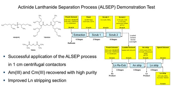
  • The co-extraction section was reduced to 6 stages and scrub 2 section increased to 8 stages to enable more complete Mo scrubbing.
  • Distribution data from single-stage contactor tests were used in the AMUSE code with no further adjustment of stage efficiency.
  • Results using the final D values (steady state) as well as with average D values (excluding first and second samples) during the single-stage tests were both used to evaluate recovery.
  • Scrub 1 D values were assumed the same as the extraction D values.
The experimental D values utilized in the modeling from the single-stage contactor tests are summarized in Table S7. Both the final D values (steady state) as well as the average D values (excluding first and second samples) during the single-stage tests were listed and were used to determine the recovery of each element. These results are presented in Table 3. The calculations predicted that 99.9% Am and 99.99% Cm would be recovered. The trivalent lanthanides recovery was calculated to range from 10% for La to >99.99% for Gd. The heavier Ln(III) are better extracted in the ALSEP system, as reflected by the increasing recovery. Yttrium was calculated to be recovered with 47–78%, depending on which D values were used for the calculations. The number of Scrub 2 stages was predicted to be suitable to reach a carryover of <0.01% of the Mo into the MA separation section. The data from the single-stage tests showed measured extraction D values to be low (approx. 0.3) in the transient samples but 4.9 when equilibrated. However, even assuming a D value of 4.9 in the extraction stages, the recovery of Mo was found to be less than 0.1% due to the low scrub D values. Iron was found to extract only slightly (0.2–0.6%).
Based on the AMUSE calculation, the flowsheet shown in Figure 7 was developed and tested in the countercurrent test.

3.3. Full Countercurrent Test and Radiochemical Analyses

The ALSEP process demonstration was run in the 1 cm annular miniature centrifugal contactor setup, installed in the laboratories of Forschungszentrum Jülich, Germany. The tested flowsheet is shown in Figure 7. Because only 16 contactors were available in the testing rig, the test had to be split into two parts and run on consecutive days. On the first day, the extraction and scrubbing stages were performed and the loaded solvent was collected and stored overnight. On the next day, the collected loaded solvent was used as the organic feed (as shown in Figure 7), and the Ln re-extraction, MA stripping, and Ln stripping sections of the flowsheet were run. On both days the experiments were run until steady state was reached. During the first day, the test was continued until enough loaded solvent for the second day was collected. The outlets of the centrifugal contactor battery (raffinate, loaded solvent, An product, Ln product, and spent solvent) were monitored by sampling and quick gamma measurements of 241Am and 152Eu. These initial gamma spectroscopy results were used to assess the approach to steady state during the test.
After stopping the tests (stopping pumps and contactors), the contents of the mixing chambers were quickly transferred to test tubes and centrifuged to achieve quantitative phase separation. Both phases were samples and analyzed by gamma and alpha spectroscopy and ICP-MS analysis, and the pH was measured or the aqueous phase was titrated, depending on the HNO3 concentration.
The stage profiles for Am and Eu, as well as Am and Cm are shown in Figure 8 and Figure S1, respectively. Americium and Cm showed comparable profiles. Figure S2 shows the corresponding distribution ratios. The results for several elements analyzed by different analytical techniques were compared to each other and found to be in very good agreement (e.g., Am profiles were determined by gamma, alpha, and ICP-MS measurements).
Americium, Cm, and Eu were well extracted and stayed in the organic phase during the scrubbing steps. The An/Ln separation worked well, as Am and Cm were mostly routed to the An product, whereas Eu was nearly quantitatively routed to the Ln product. A slight Am and Cm recycling was observed in the Ln re-extraction section, presumably due to a slight pH change in stages 17–22 from pH 1.7 to pH 1.9, similar to observations reported by Gelis et al. [27] This pH change was attributed to the acidic extractant introduced with the fresh solvent stream, which had not been pre-equilibrated prior to the experiment. The pH values in the An stripping section (stages 23–28) were relatively constant at pH 1.9–2.0. The measured pH values or H+ concentrations are shown in Figure 9.
The An(III) product was fairly clean with only very low contaminations, resulting in excellent decontamination factors (see Table 4). However, a small fraction of Am and Cm (ca. 5%) was routed to the Ln product. Apparently, the number of An stripping stages was insufficient to achieve a quantitative An/Ln separation. The Am and Cm stage profiles suggest that two additional An stripping stages would have resulted in near complete separation of the An from the Ln.
The Ln stripping with TEDGA worked very well and four stages were sufficient for a good back-extraction from the solvent. The only contaminants found in the spent solvent were Fe (12.1%), Sn (0.8%), and Pd (0.1%). As discussed below, the Fe content found in the spent solvent probably stems from a slight corrosion of the stainless-steel contactor housing, as some Cr (typical stainless-steel additive) was also found in those samples (Cr was not added with the feed).
Evaluation of the ICP-MS data show that the non-Ln fission products were mostly routed to the raffinate. Palladium and Zr masking in the feed with CDTA was effective, and the Mo scrubbing also worked well, as predicted by AMUSE calculations. The Mo and Zr stage profiles are shown in Figure 10. The heavier lanthanides (Pr, Nd, Sm, Eu, and Gd) and Y were mainly routed to the Ln product, whereas the lighter lanthanides (La, Ce) were also partly found in the raffinate, as expected based on previous batch distribution measurements and flowsheet calculations. Table 4 shows the mass balances, recoveries, process, and An/Ln decontamination factors, as well as product concentration factors obtained during the ALSEP test. The overall Fe mass balance suggests slight corrosion of the stainless-steel contactor housing, as Fe was found in all process streams with a >100% mass balance. Furthermore, the spent solvent contained a relatively high amount of Fe, supporting the assumption that the solvent has some corrosive effect on the stainless-steel contactor housing. Iron is fairly strongly extracted into the ALSEP solvent. However, its extraction is slow, so the extent of extraction will depend on the residence time in the contactors.
Figures S3–S5 show the stage profiles for La, Ce, Pr, Nd, Sm, and Gd.

4. Conclusions

The successful application of the ALSEP process in 1 cm centrifugal contactors was demonstrated. Trivalent Am and Cm were recovered with high purity from a simulated raffinate solution and only slight losses of An(III) to the Ln product were observed. These losses can be minimized using a higher number of An stripping stages. The demonstration tests described in this paper used an improved Ln stripping section. The use of TEDGA proved very successful in almost quantitative stripping of trivalent metal ions, which is an improvement over previous demonstration tests. The spent solvent only contained slight contaminations of iron, probably from slow corrosion of the stainless-steel contactor housing, which should be addressed before implementation on a larger scale.

Supplementary Materials

The following are available online at https://www.mdpi.com/2076-3417/10/20/7217/s1, Table S1: Distribution ratios D, mass balances, and stage efficiencies in the extraction single centrifugal contactor test, Table S2: Feed concentrations, distribution ratios D, mass balances, and stage efficiencies in the Scrub 2 single centrifugal contactor test, Table S3: Feed concentrations, distribution ratios D, mass balances, and stage efficiencies in the An stripping single centrifugal contactor test, Table S4: Feed concentrations, distribution ratios D, mass balances, and stage efficiencies in the Ln re-extraction single centrifugal contactor test, Table S5: Distribution ratios D as a function of the HNO3 and N,N,N′,N′-tetraethyl-diglycolamide (TEDGA) concentrations in the Ln stripping batch tests, Table S6: Feed concentrations, distribution ratios D, mass balances, and stage efficiencies in the Ln stripping single centrifugal contactor test, Table S7: D values used for the flowsheet calculations with the AMUSE code, Figure S1: Am and Cm stage profiles of the Actinide Lanthanide Separation Process (ALSEP) demonstration test (data from alpha spectrometry), Figure S2: Am, Cm, and Eu distribution ratios in the stages of the ALSEP demonstration test (Am, Eu data from inductively coupled plasma mass spectrometry (ICP-MS) measurements, and Cm data from alpha spectrometry), Figure S3: La and Ce stage profiles of the ALSEP demonstration test (data from ICP-MS measurements), Figure S4: Pr and Nd stage profiles of the ALSEP demonstration test (data from ICP-MS measurements), Figure S5: Sm and Gd stage profiles of the ALSEP demonstration test (data from ICP-MS measurements).

Author Contributions

Conceptualization, A.W., G.M., G.J.L., A.V.G., J.D.L., and A.G.; investigation, A.W., F.K., D.S., Z.P., G.M., G.J.L., A.V.G., J.D.L., and A.G.; software, J.D.L. and A.G.; validation, A.W., G.M., G.J.L., A.V.G., J.D.L., and A.G.; data curation, A.W., F.K., D.S., and Z.P.; writing—original draft preparation, A.W.; writing—review and editing, F.K., D.S., Z.P., G.M., G.J.L., A.V.G., J.D.L., and A.G.; visualization, A.W.; supervision, G.M., G.J.L., A.V.G., J.D.L., and A.G.; project administration, G.M.; funding acquisition, G.M., J.D.L., and A.W. All authors have read and agreed to the published version of the manuscript.

Funding

Funding for this research was provided by the Battelle Energy Alliance, LLC, under Contract No. 00216406 and the European Commission through the GEN IV Integrated Oxide Fuels Recycling Strategies (GENIORS) project, grant agreement No. 730227. Additionally, this work was funded by the U.S. Department of Energy’s Office of Nuclear Energy, through the Nuclear Technologies Research and Development Program. Pacific Northwest National Laboratory is operated by Battelle Memorial Institute for the U.S. Department of Energy under contract DE-AC05-76RL01830.

Conflicts of Interest

The authors declare no conflict of interest.

References

  1. Taylor, R.J. (Ed.) Reprocessing and Recycling of Spent Nuclear Fuel; Woodhead Publishing: Cambridge, UK, C2013-0-16483-5; 2015. [Google Scholar]
  2. OECD-NEA. Transition towards a Sustainable Nuclear Fuel Cycle; NEA No. 7133; OECD Nuclear Energy Agency: Paris, France, 2013. [Google Scholar]
  3. OECD-NEA. State-of-the-Art Report on the Progress of Nuclear Fuel Cycle Chemistry; NEA No. 7267; OECD Nuclear Energy Agency: Paris, France, 2018. [Google Scholar]
  4. Taylor, R.; Bourg, S.; Glatz, J.-P.; Modolo, G. Development of actinide separation processes for future nuclear fuel cycles in Europe. Nucl. Future 2015, 11, 38–43. [Google Scholar]
  5. Moyer, B.A.; Lumetta, G.J.; Mincher, B.J. Minor actinide separation in the reprocessing of spent nuclear fuels: Recent advances in the United States. In Reprocessing and Recycling of Spent Nuclear Fuel; Taylor, R., Ed.; Woodhead Publishing: Oxford, UK, 2015; pp. 289–312. [Google Scholar] [CrossRef]
  6. Poinssot, C.; Bourg, S.; Ouvrier, N.; Combernoux, N.; Rostaing, C.; Vargas-Gonzalez, M.; Bruno, J. Assessment of the environmental footprint of nuclear energy systems. Comparison between closed and open fuel cycles. Energy 2014, 69, 199–211. [Google Scholar] [CrossRef] [Green Version]
  7. Poinssot, C.; Bourg, S.; Boullis, B. Improving the nuclear energy sustainability by decreasing its environmental footprint. Guidelines from life cycle assessment simulations. Prog. Nucl. Energy 2016, 92, 234–241. [Google Scholar] [CrossRef]
  8. Serp, J.; Poinssot, C.; Bourg, S. Assessment of the Anticipated Environmental Footprint of Future Nuclear Energy Systems. Evidence of the Beneficial Effect of Extensive Recycling. Energies 2017, 10, 1445. [Google Scholar] [CrossRef] [Green Version]
  9. Lanham, W.B.; Runion, T.C. PUREX Process for Plutonium and Uranium Recovery; ORNL-479; Oak Ridge National Laboratory: Oak Ridge, TN, USA, 1949. [Google Scholar]
  10. Dinh, B.; Moisy, P.; Baron, P.; Calor, J.-N.; Espinoux, D.; Lorrain, B.; Benchikouhne-Ranchoux, M. Modified PUREX first-cycle extraction for neptunium recovery. In Proceedings of the 18th International Solvent Extraction Conference (ISEC), Tuscon, AZ, USA, 15–19 September 2008; pp. 581–586. [Google Scholar]
  11. Taylor, R.J.; Gregson, C.R.; Carrott, M.J.; Mason, C.; Sarsfield, M.J. Progress towards the Full Recovery of Neptunium in an Advanced PUREX Process. Solvent Extr. Ion Exch. 2013, 31, 442–462. [Google Scholar] [CrossRef]
  12. Modolo, G.; Wilden, A.; Geist, A.; Magnusson, D.; Malmbeck, R. A review of the demonstration of innovative solvent extraction processes for the recovery of trivalent minor actinides from PUREX raffinate. Radiochim. Acta 2012, 100, 715–725. [Google Scholar] [CrossRef]
  13. Modolo, G.; Geist, A.; Miguirditchian, M. Minor actinide separations in the reprocessing of spent nuclear fuels: Recent advances in Europe. In Reprocessing and Recycling of Spent Nuclear Fuel; Taylor, R., Ed.; Woodhead Publishing: Oxford, UK, 2015; pp. 245–287. [Google Scholar] [CrossRef]
  14. Veliscek-Carolan, J. Separation of Actinides from Spent Nuclear Fuel: A Review. J. Hazard. Mater. 2016, 318, 266–281. [Google Scholar] [CrossRef]
  15. Baron, P.; Cornet, S.M.; Collins, E.D.; DeAngelis, G.; Del Cul, G.; Fedorov, Y.; Glatz, J.P.; Ignatiev, V.; Inoue, T.; Khaperskaya, A.; et al. A review of separation processes proposed for advanced fuel cycles based on technology readiness level assessments. Prog. Nucl. Energy 2019, 117, 24. [Google Scholar] [CrossRef]
  16. Miguirditchian, M.; Vanel, V.; Marie, C.; Pacary, V.; Charbonnel, M.-C.; Berthon, L.; Hérès, X.; Montuir, M.; Sorel, C.; Bollesteros, M.-J.; et al. Americium Recovery from Highly Active PUREX Raffinate by Solvent Extraction: The EXAm Process. A Review of 10 Years of R&D. Solvent Extr. Ion Exch. 2020, 38, 365–387. [Google Scholar] [CrossRef]
  17. Wilden, A.; Modolo, G.; Schreinemachers, C.; Sadowski, F.; Lange, S.; Sypula, M.; Magnusson, D.; Geist, A.; Lewis, F.W.; Harwood, L.M.; et al. Direct Selective Extraction of Actinides (III) from PUREX Raffinate using a Mixture of CyMe4BTBP and TODGA as 1-cycle SANEX Solvent Part III: Demonstration of a Laboratory-scale Counter-Current Centrifugal Contactor Process. Solvent Extr. Ion Exch. 2013, 31, 519–537. [Google Scholar] [CrossRef]
  18. Gelis, A.V.; Lumetta, G.J. Actinide Lanthanide Separation Process-ALSEP. Ind. Eng. Chem. Res. 2014, 53, 1624–1631. [Google Scholar] [CrossRef]
  19. Wilden, A.; Modolo, G.; Kaufholz, P.; Sadowski, F.; Lange, S.; Munzel, D.; Geist, A. Process Development and Laboratory-scale Demonstration of a regular-SANEX Process Using C5-BPP. Sep. Sci. Technol. 2015, 50, 2467–2475. [Google Scholar] [CrossRef]
  20. Wilden, A.; Modolo, G.; Kaufholz, P.; Sadowski, F.; Lange, S.; Sypula, M.; Magnusson, D.; Müllich, U.; Geist, A.; Bosbach, D. Laboratory-Scale Counter-Current Centrifugal Contactor Demonstration of an Innovative-SANEX Process Using a Water Soluble BTP. Solvent Extr. Ion Exch. 2015, 33, 91–108. [Google Scholar] [CrossRef]
  21. Carrott, M.; Maher, C.; Mason, C.; Sarsfield, M.; Taylor, R. “TRU-SANEX”: A variation on the EURO-GANEX and i-SANEX processes for heterogeneous recycling of actinides Np-Cm. Sep. Sci. Technol. 2016, 51, 2198–2213. [Google Scholar] [CrossRef]
  22. Marie, C.; Kaufholz, P.; Vanel, V.; Duchesne, M.-T.; Russello, E.; Faroldi, F.; Baldini, L.; Casnati, A.; Wilden, A.; Modolo, G.; et al. Development of a Selective Americium Separation Process Using H4TPAEN as Water-Soluble Stripping Agent. Solvent Extr. Ion Exch. 2019, 37, 313–327. [Google Scholar] [CrossRef]
  23. Lumetta, G.J.; Gelis, A.V.; Carter, J.C.; Niver, C.M.; Smoot, M.R. The Actinide-Lanthanide Separation Concept. Solvent Extr. Ion Exch. 2014, 32, 333–347. [Google Scholar] [CrossRef]
  24. Brown, M.A.; Wardle, K.E.; Lumetta, G.; Gelis, A.V. Accomplishing Equilibrium in ALSEP: Demonstrations of Modified Process Chemistry on 3-D Printed Enhanced Annular Centrifugal Contactors. Procedia Chem. 2016, 21, 167–173. [Google Scholar] [CrossRef]
  25. Holfeltz, V.E.; Campbell, E.L.; Peterman, D.R.; Standaert, R.F.; Paulenova, A.; Lumetta, G.J.; Levitskaia, T.G. Effect of HEH[EHP] impurities on the ALSEP solvent extraction process. Solvent Extr. Ion Exch. 2017, 36, 22–40. [Google Scholar] [CrossRef]
  26. Peterman, D.R.; Zarzana, C.A.; Tillotson, R.D.; McDowell, R.G.; Rae, C.; Groenewold, G.S.; Law, J.D. Evaluation of the impacts of gamma radiolysis on an ALSEP process solvent. J. Radioanal. Nucl. Chem. 2018, 316, 855–860. [Google Scholar] [CrossRef]
  27. Gelis, A.V.; Kozak, P.; Breshears, A.T.; Brown, M.A.; Launiere, C.; Campbell, E.L.; Hall, G.B.; Levitskaia, T.G.; Holfeltz, V.E.; Lumetta, G.J. Closing the Nuclear Fuel Cycle with a Simplified Minor Actinide Lanthanide Separation Process (ALSEP) and Additive Manufacturing. Sci. Rep. 2019, 9, 12842. [Google Scholar] [CrossRef]
  28. Picayo, G.A.; Etz, B.D.; Vyas, S.; Jensen, M.P. Characterization of the ALSEP Process at Equilibrium: Speciation and Stoichiometry of the Extracted Complex. ACS Omega 2020, 5, 8076–8089. [Google Scholar] [CrossRef] [PubMed]
  29. Hall, G.B.; Holfeltz, V.E.; Campbell, E.L.; Boglaienko, D.; Lumetta, G.J.; Levitskaia, T.G. Evolution of Acid-Dependent Am3+ and Eu3+ Organic Coordination Environment: Effects on the Extraction Efficiency. Inorg. Chem. 2020, 59, 4453–4467. [Google Scholar] [CrossRef] [PubMed]
  30. Sypula, M.; Wilden, A.; Schreinemachers, C.; Malmbeck, R.; Geist, A.; Taylor, R.; Modolo, G. Use of polyaminocarboxylic acids as hydrophilic masking agents for fission products in actinide partitioning processes. Solvent Extr. Ion Exch. 2012, 30, 748–764. [Google Scholar] [CrossRef]
  31. Lumetta, G.J.; Allred, J.R.; Bryan, S.A.; Hall, G.B.; Levitskaia, T.G.; Lines, A.M.; Sinkov, S.I. Simulant Testing of a Co-decontamination (CoDCon) Flowsheet for a Product with a Controlled Uranium-to-Plutonium Ratio. Sep. Sci. Technol. 2019, 54, 1977–1984. [Google Scholar] [CrossRef]
  32. Hu, Z.; Pan, Y.; Ma, W.; Fu, X. Purification of Organophosphorus Acid Extractants. Solvent Extr. Ion Exch. 1995, 13, 965–976. [Google Scholar] [CrossRef]
  33. Leonard, R.A. Design Principles and Applications of Centrifugal Contactors for Solvent Extraction. In Ion Exchange and Solvent Extraction, A Series of Advances; Moyer, B.A., Ed.; CRC Taylor and Francis: Boca Raton, FL, USA, 2009; Volume 19, pp. 563–616. [Google Scholar]
  34. Duan, W.; Zhao, M.; Wang, C.; Cao, S. Recent Advances in the Development and Application of Annular Centrifugal Contactors in the Nuclear Industry. Solvent Extr. Ion Exch. 2014, 32, 1–26. [Google Scholar] [CrossRef]
  35. Lumetta, G.J.; Campbell, E.L.; Casella, A.J.; Hall, G.B.; Holfeltz, V.E.; Levitskaia, T.G. Sigma Team for Advanced Actinide Recovery: PNNL FY 2016 Summary Report; FCRD-MRWFD-2016-000324; U.S. Department of Energy, Sigma Team for Advanced Actinide Recovery, Pacific Northwest National Laboratory: Richland, WA, USA, 2016.
  36. Chapron, S.; Marie, C.; Arrachart, G.; Miguirditchian, M.; Pellet-Rostaing, S. New Insight into the Americium/Curium Separation by Solvent Extraction Using Diglycolamides. Solvent Extr. Ion Exch. 2015, 33, 236–248. [Google Scholar] [CrossRef]
  37. Herdzik-Koniecko, I.; Wagner, C.; Trumm, M.; Müllich, U.; Schimmelpfennig, B.; Narbutt, J.; Geist, A.; Panak, P.J. Do An(III) and Ln(III) ions form heteroleptic complexes with diglycolamide and hydrophilic BT(B)P ligands in solvent extraction systems? A spectroscopic and DFT study. New J. Chem. 2019, 43, 6314–6322. [Google Scholar] [CrossRef] [Green Version]
  38. Klaß, L.; Wilden, A.; Kreft, F.; Wagner, C.; Geist, A.; Panak, P.J.; Herdzik-Koniecko, I.; Narbutt, J.; Modolo, G. Evaluation of the Hydrophilic Complexant N,N,N′,N′-tetraethyldiglycolamide (TEDGA) and its Methyl-substituted Analogues in the Selective Am(III) Separation. Solvent Extr. Ion Exch. 2019, 37, 297–312. [Google Scholar] [CrossRef]
  39. Frey, K.; Krebs, J.F.; Pereira, C. Time-Dependent Implementation of Argonne’s Model for Universal Solvent Extraction. Ind. Eng. Chem. Res. 2012, 51, 13219–13226. [Google Scholar] [CrossRef]
Figure 1. Chemical structures of molecules used in this study.
Applsci 10 07217 g001
Figure 2. Am, Cm, and Eu distribution ratios as a function of the experimental run time (data points) and equilibrium values (horizontal lines) in the extraction section single centrifugal contactor test. “g”, “a”, and “ICP” indicate values measured by gamma and alpha spectrometry as well as inductively coupled plasma mass spectrometry (ICP-MS), respectively.
Applsci 10 07217 g002
Figure 3. Am, Cm, and Eu distribution ratios as a function of the experimental run time (data points) and equilibrium values (horizontal lines) in the Scrub 2 section single centrifugal contactor test. “g”, “a”, and “I” indicate values measured by gamma and alpha spectrometry as well as ICP-MS, respectively.
Applsci 10 07217 g003
Figure 4. Am, Cm, and Eu distribution ratios as a function of the experimental run time (data points) and equilibrium values (horizontal lines) in the An stripping section single centrifugal contactor test. “g”, “a”, and “I” indicate values measured by gamma and alpha spectrometry as well as ICP-MS, respectively.
Applsci 10 07217 g004
Figure 5. Am, Cm, and Eu distribution ratios as a function of the experimental run time (data points) and equilibrium values (horizontal lines) in the Ln re-extraction section single centrifugal contactor test. “g”, “a”, and “I” indicate values measured by gamma and alpha spectrometry as well as ICP-MS, respectively.
Applsci 10 07217 g005
Figure 6. Am, Cm, and Eu distribution ratios as a function of the experimental run time (data points) and equilibrium values (horizontal lines) in the Ln stripping section single centrifugal contactor test. “g”, “a”, and “I” indicate values measured by gamma and alpha spectrometry as well as ICP-MS, respectively.
Applsci 10 07217 g006
Figure 7. Flowsheet of the Actinide Lanthanide Separation Process (ALSEP) process demonstration.
Applsci 10 07217 g007
Figure 8. Am and Eu stage profiles of the ALSEP demonstration test (data from ICP-MS measurements, in very well agreement with data from gamma spectrometry).
Applsci 10 07217 g008
Figure 9. Measured pH values or titrated H+ concentration in the stages of the ALSEP demonstration test. Note that the right y-axis is plotted upside down.
Applsci 10 07217 g009
Figure 10. Mo and Zr stage profiles of the ALSEP demonstration test (data from ICP-MS measurements).
Applsci 10 07217 g010
Table 1. Composition of the synthetic Actinide Lanthanide Separation Process (ALSEP) feed solution.
ElementConcentration ALSEP Feed [mg L−1] *ElementConcentration ALSEP Feed [mg L−1] *
Fe7Cs665
Rb90La309
Sr207Ce591
Y119Pr267
Zr718Nd1003
Mo425Sm213
Ru296Eu44
Rh1Gd45
Pd6241Am3.1 MBq L−1
Sn14244Cm3.0 MBq L−1
Te69152Eu5.6 MBq L−1
HNO32.9 mol L−1
* or as shown.
Table 2. Flow rates used in the different single centrifugal contactor tests and composition of the aqueous phases used to start operation.
SectionAq. Flow Rate [mL h−1]Org. Flow Rate [mL h−1]Contactor Filled with *
Extraction72243 mol L−1 HNO3
Mo scrubbing (Scrub 2)3024Fresh Scrub 2 solution
MA stripping1836Fresh Strip 1 solution
Ln re-extraction1818Fresh Strip 1 solution
Ln stripping5436Fresh 0.5 mol L−1 TEDGA in 0.5 mol L−1 HNO3
* organic phase always fresh ALSEP solvent.
Table 3. Predicted recovery into solvent exiting Scrub 2 section.
Recovery in the Loaded Solvent after Scrub 2
Steady StateAverage
Am99.87%99.92%
Eu>99.99%>99.99%
Cm99.99%99.97%
La10.00%10.70%
Ce70.20%72.80%
Pr96.90%97.40%
Nd99.70%99.80%
Sm>99.99%>99.99%
Eu>99.99%>99.99%
Gd>99.99%>99.98%
Mo<0.01%<0.01%
Fe0.64%0.16%
Zr<0.01%0.01%
Ru<0.01%<0.01%
Rb<0.01%<0.01%
Sr<0.01%<0.01%
Cs<0.01%<0.01%
Y47.00%78.00%
Rh<0.01%<0.01%
Pd<0.01%<0.01%
Sn<0.01%<0.01%
Te<0.01%<0.01%
Table 4. Mass balances, recoveries, process, and An/Ln decontamination factors (DF), as well as product concentration factors (CF) obtained during the ALSEP test.
ElementRaffinate [%]Loaded Solvent [%]An Product [%]Ln Product [%]Spent Solvent [%]DFfeed/An productDFAm/MDFCm/MCFproduct/feed
241Am<0.1>99.995.74.3<0.11.041.000.990.48
244Cm<0.1>99.994.35.7<0.11.061.011.000.47
Fe *86.58.46.03.012.116.716.015.70.03
Rb>99.9<0.1<0.1<0.1<0.1≥1000≥957≥943≤0.001
Sr>99.9<0.1<0.1<0.1<0.1≥1000≥957≥943≤0.001
Y<0.1>99.9<0.1>99.9<0.1≥1000≥957≥943≤0.001
Zr99.80.20.2<0.1<0.1≥500≥479≥472≤0.001
Mo>99.9<0.1<0.1<0.1<0.1≥1000≥957≥943≤0.001
Ru>99.9<0.1<0.1<0.1<0.1≥1000≥957≥943≤0.001
Rh>99.9<0.1<0.1<0.1<0.1≥1000≥957≥943≤0.001
Pd99.60.40.10.20.1≥1000≥957≥943≤0.001
Sn99.10.90.1<0.10.8≥1000≥957≥943≤0.001
Te98.9<0.1<0.1<0.1<0.1≥1000≥957≥943≤0.001
Cs>99.9<0.1<0.1<0.1<0.1≥1000≥957≥943≤0.001
La94.15.9<0.15.9<0.1≥1000≥957≥943≤0.001
Ce16.383.7<0.183.7<0.1≥1000≥957≥943≤0.001
Pr0.699.4<0.199.4<0.1≥1000≥957≥943≤0.001
Nd0.199.9<0.199.9<0.1≥1000≥957≥943≤0.001
Sm<0.1>99.9<0.1>99.9<0.1≥1000≥957≥943≤0.001
Eu<0.1>99.9<0.1>99.9<0.1≥1000≥957≥943≤0.001
Gd0.699.4<0.199.4<0.1≥1000≥957≥943≤0.001
* The overall Fe mass balance suggests slight corrosion of the steel contactor housing. Additionally, increased Cr concentrations were measured in those samples (Cr is a typical stainless-steel additive and was not added to the feed).
Publisher’s Note: MDPI stays neutral with regard to jurisdictional claims in published maps and institutional affiliations.

