A Ka-Band Circular Polarized Waveguide Slot Antenna with a Cross Iris


Abstract
:Featured Application
Abstract
1. Introduction
2. Antenna Design
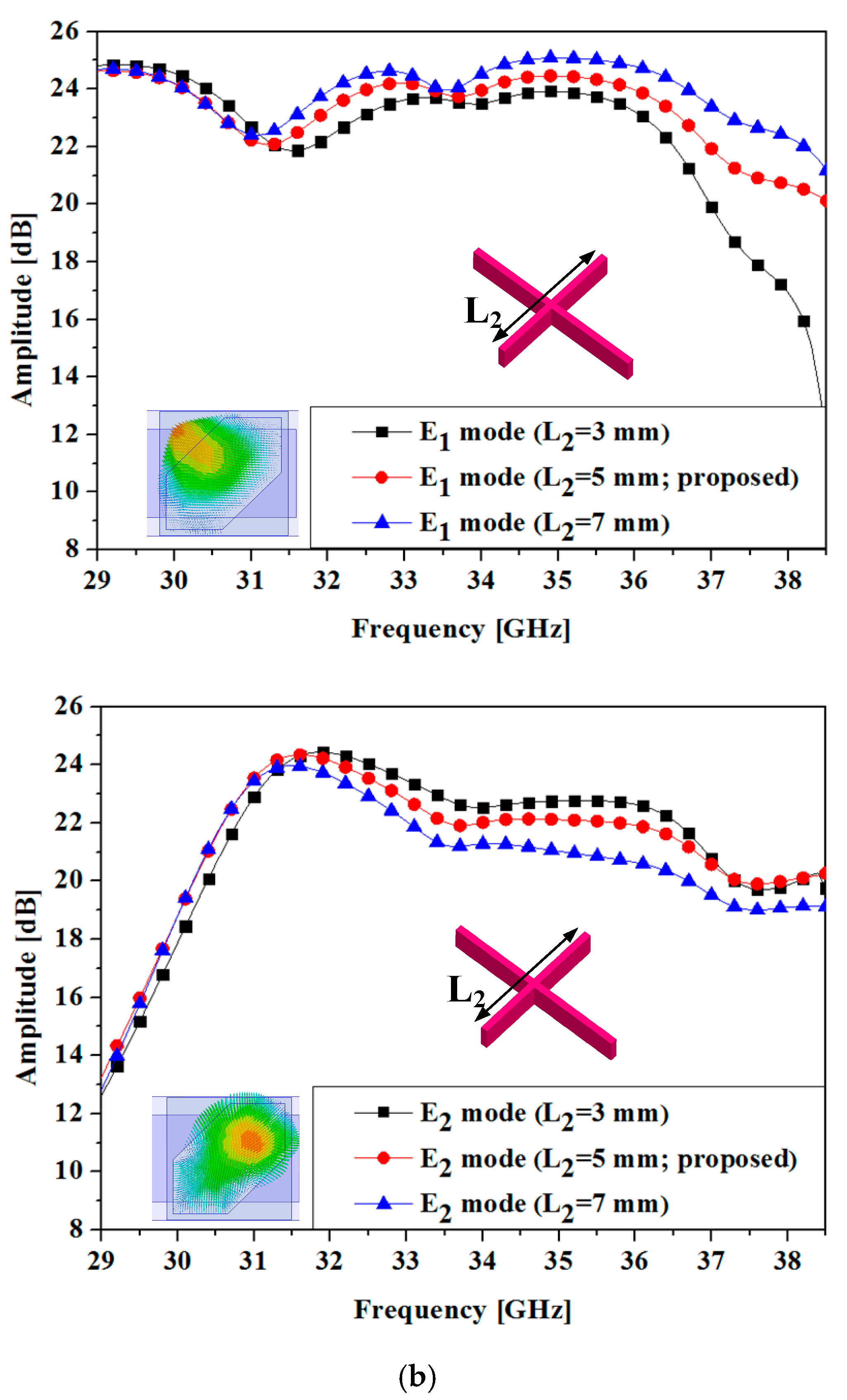
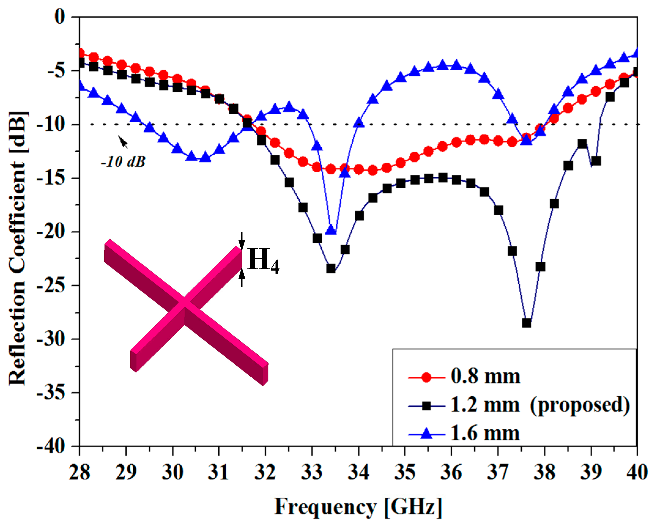
3. Antenna Analysis
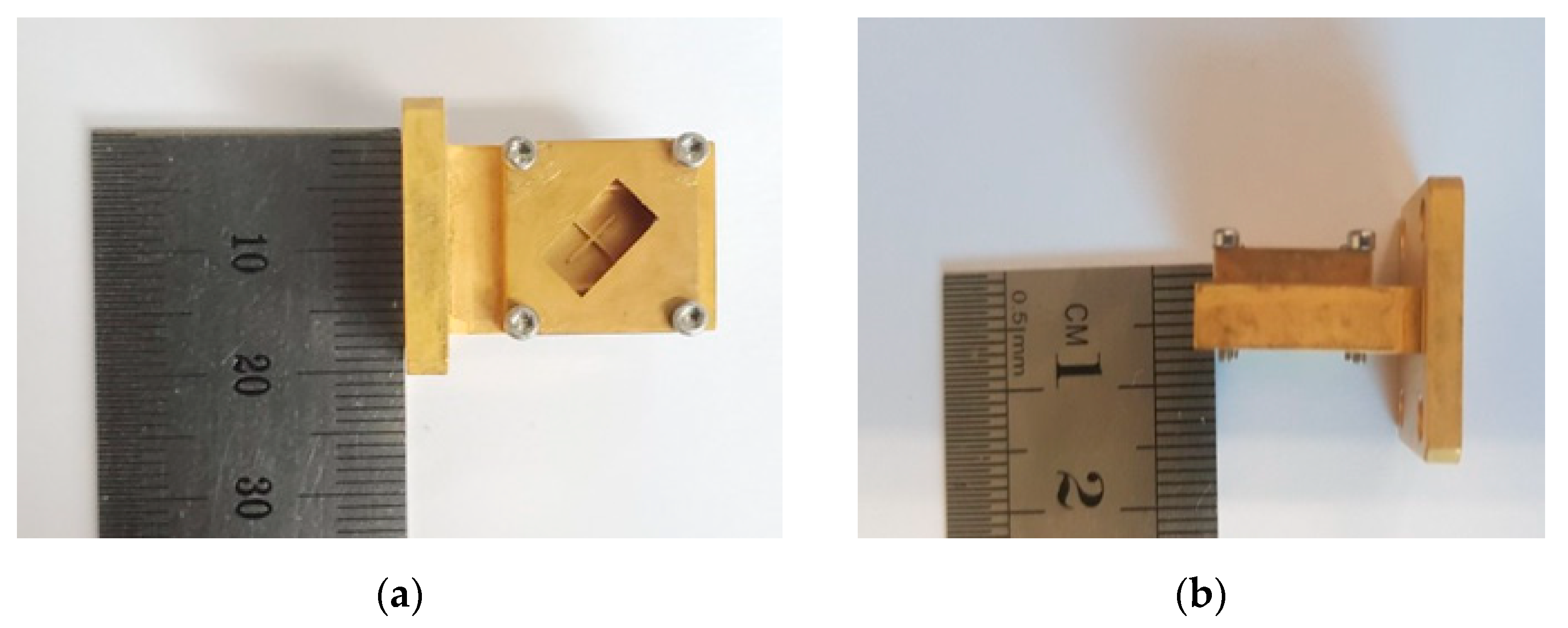
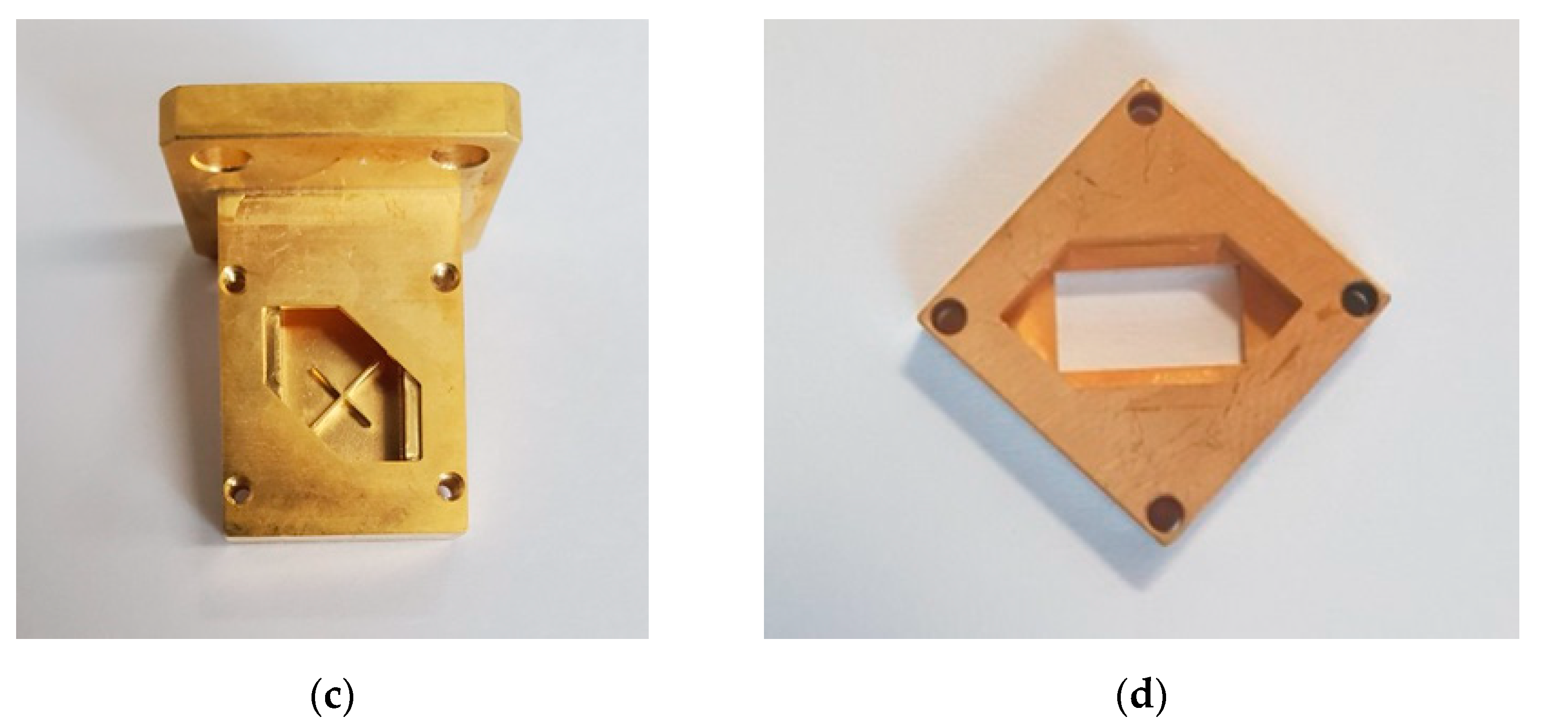
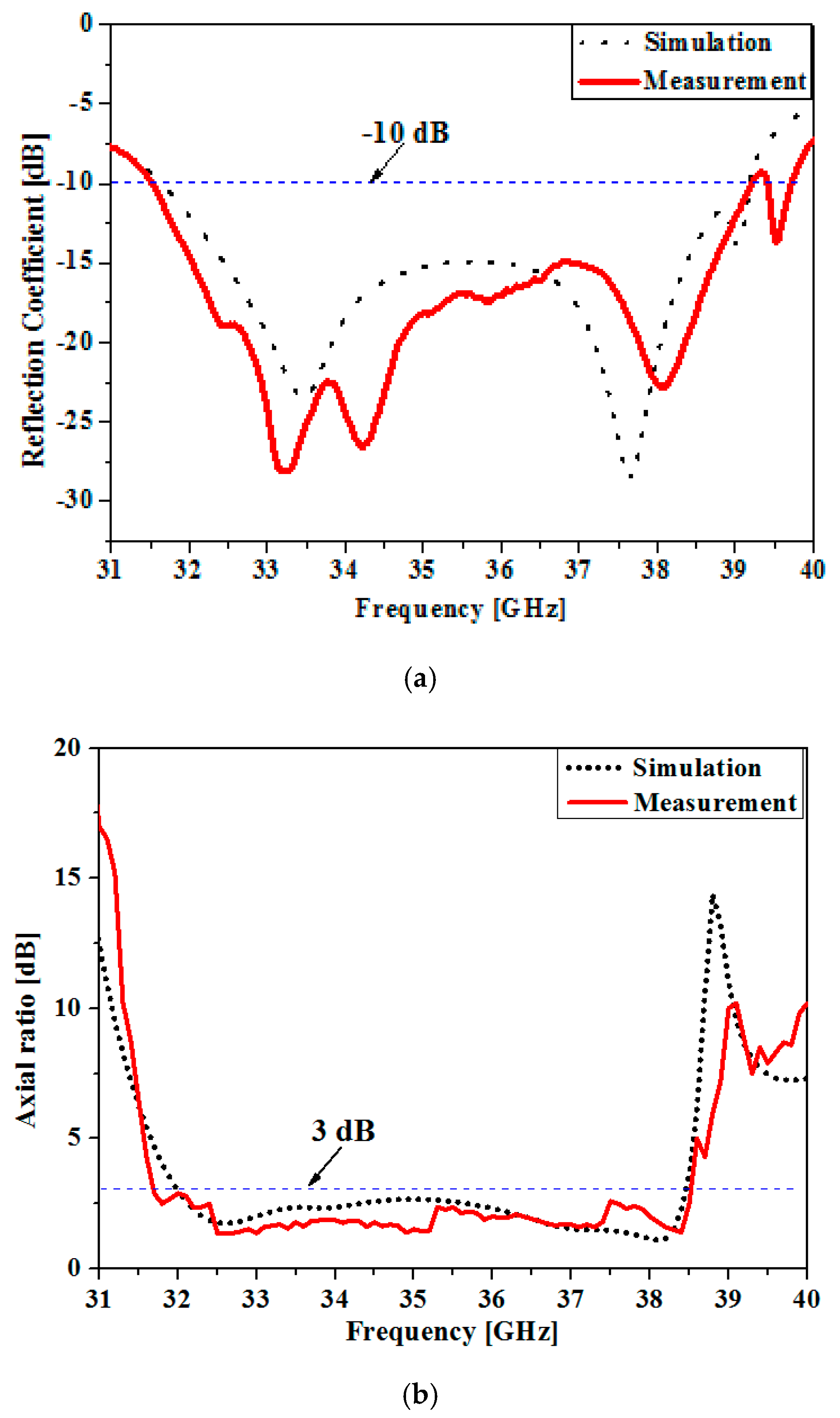
4. Experimental Results
5. Conclusions
Author Contributions
Funding
Conflicts of Interest
References
- Rappaport, T.S.; Xing, Y.; MacCartney, G.R.; Molisch, A.F.; Mellios, E.; Zhang, J. Overview of millimeter wave communications for fifth-generation (5g) wireless networks—with a focus on propagation models. IEEE Trans. Antennas Propag. 2017, 65, 6213–6230. [Google Scholar] [CrossRef]
- Leung, K.W.; So, K. Rectangular waveguide excitation of dielectric resonator antenna. IEEE Trans. Antennas Propag. 2003, 51, 2477–2481. [Google Scholar] [CrossRef]
- Montisci, G.; Musa, M.; Mazzarella, G. Waveguide slot antennas for circularly polarized radiated field. IEEE Trans. Antennas Propag. 2004, 52, 619–623. [Google Scholar] [CrossRef]
- Fukusako, T. Broadband characterization of circularly polarized waveguide antennas using l-shaped probe. J. Electromagn. Eng. Sci. 2017, 17, 1–8. [Google Scholar] [CrossRef] [Green Version]
- Wang, M.; Hu, L.; Chen, J.; Qi, S.-S.; Wu, W. Wideband circularly polarized square slot array fed by slotted waveguide for satellite communication. Prog. Electromagn. Res. Lett. 2016, 61, 111–118. [Google Scholar] [CrossRef] [Green Version]
- Ma, X.; Huang, C.; Pan, W.; Zhao, B.; Cui, J.; Luo, X. A dual circularly polarized horn antenna in ku-band based on chiral metamaterial. IEEE Trans. Antennas Propag. 2014, 62, 2307–2311. [Google Scholar] [CrossRef]
- Qi, S.-S.; Wu, W.; Fang, D.-G. Singly-fed circularly polarized circular aperture antenna with conical beam. IEEE Trans. Antennas Propag. 2013, 61, 3345–3349. [Google Scholar] [CrossRef]
- Zhao, Y.; Wei, K.; Zhang, Z.; Feng, Z. A waveguide antenna with bidirectional circular polarizations of the same sense. IEEE Antennas Wirel. Propag. Lett. 2013, 12, 559–562. [Google Scholar] [CrossRef]
- Lin, C.; Ge, Y.; Bird, T.S.; Liu, K. Circularly polarized horns based on standard horns and a metasurface polarizer. IEEE Antennas Wirel. Propag. Lett. 2018, 17, 480–484. [Google Scholar] [CrossRef]
- Zhang, T.-L.; Yan, Z.-H. A ka dual-band circular waveguide polarizer. In Proceedings of the 2006 7th International Symposium on Antennas, Propagation & EM Theory, Guilin, China, 26 October 2006; Institute of Electrical and Electronics Engineers (IEEE): Piscataway, NJ, USA, 2006; pp. 1–4. [Google Scholar]
- Ferrando-Rocher, M.; Herranz-Herruzo, J.I.; Valero-Nogueira, A.; Rodrigo, V.M.; Rodrigo-Penarrocha, V. Circularly polarized slotted waveguide array with improved axial ratio performance. IEEE Trans. Antennas Propag. 2016, 64, 4144–4148. [Google Scholar] [CrossRef] [Green Version]
- Li, T.; Fan, F. Design of ka-band 2×2 circular polarization slot antenna array fed by ridge gap waveguide. In Proceedings of the 2017 Sixth Asia-Pacific Conference on Antennas and Propagation (APCAP), Xi’an, China, 6–19 October 2017; pp. 1–3. [Google Scholar]
- Hirano, T.; Hirokawa, J.; Ando, M. Waveguide matching crossed-slot. IEEE Proc.-Microw. Antennas Propag. 2003, 150, 143–146. [Google Scholar] [CrossRef]
- Salari, M.; Movahhedi, M. A new configuration for circularly polarized waveguide slot antenna. In Proceedings of the Asia-Pacific Microwave Conference 2011, Melbourne, Australia, 5–8 December 2011; pp. 606–609. [Google Scholar]
- Montisci, G. Design of circularly polarized waveguide slot linear arrays. IEEE Trans. Antennas Propag. 2006, 54, 3025–3029. [Google Scholar] [CrossRef]
- Kai, Z.; Jianying, L.; Yi, Y.; Rui, X. A novel design of circularly polarized waveguide antenna. In Proceedings of the 2014 3rd Asia-Pacific Conference on Antennas and Propagation, Harbin, China, 26–29 July 2014; Institute of Electrical and Electronics Engineers (IEEE): Piscataway, NJ, USA, 2014; pp. 130–133. [Google Scholar]
- Wu, X.; Yang, F.; Xu, F.; Zhou, J. Circularly polarized waveguide antenna with dual pairs of radiation slots at ka-band. IEEE Antennas Wirel. Propag. Lett. 2017, 16, 2947–2950. [Google Scholar] [CrossRef]
- Bhardwaj, S.; Volakis, J.L. Circularly-polarized horn antennas for terahertz communication using differential-mode dispersion in hexagonal waveguides. In Proceedings of the 2017 IEEE International Symposium on Antennas and Propagation & USNC/URSI National Radio Science Meeting, California, CA, USA, 9–14 July 2017; pp. 2571–2572. [Google Scholar] [CrossRef]
- Ansys High Frequency Structure Simulator (HFSS); Ansys Corporation: Ansys Drive Canonsburg, PA, USA, 2018; ver.17.2.
- Pozar, D.M. Microwave Engineering, 4th ed.; John Wily & Sons, Inc.: New York, NY, USA, 2012; pp. 110–113. [Google Scholar]
- Lo, Y.; Solomon, D.; Richards, W. Theory and experiment on microstrip antennas. IRE Trans. Antennas Propag. 1979, 27, 137–145. [Google Scholar] [CrossRef]
- Gan, T.H.; Tan, E.L. Design of broadband circular polarization truncated horn antenna with single feed. Prog. Electromagn. Res. C 2011, 24, 197–206. [Google Scholar] [CrossRef] [Green Version]
- Yuan, H.; Qu, S.; Zhang, J.; Zhou, H.; Wang, J.; Ma, H.; Xu, Z. Dual-band dual-polarized spiral antenna for chinese compass navigation satellite system. Prog. Electromagn. Res. Lett. 2014, 46, 25–30. [Google Scholar] [CrossRef] [Green Version]
- Boyd, C.R. Impedance matching of open-ended waveguide radiating elements. In Proceedings of the SBMO International Microwave Symposium, Rio de Janeiro, Brazil, 27–30 July 1987. [Google Scholar]
- Park, D.; Qu, L.; Kim, H. Compact circularly polarized antenna utilizing the radiation of the ground plane based on the theory of characteristic modes. IET Microw. Antennas Propag. 2019, 13, 1509–1514. [Google Scholar] [CrossRef]
- Balanis, C.A. Antenna theory analysis and design, 3rd ed.; Wiley Interscience: Hoboken, NJ, USA, 2005; pp. 70–79. [Google Scholar]
- Chu, Q.-X.; Kang, Z.-Y.; Wu, Q.-S.; Mo, D.-Y. An in-phase output ka-band traveling-wave power divider/combiner using double ridge-waveguide couplers. IEEE Trans. Microw. Theory Tech. 2013, 61, 3247–3253. [Google Scholar] [CrossRef]


| Parameters | ||||||
| Value (mm) | 6.5 | 4.4 | 4.3 | 8 | 6 | 5 |
| Parameters | ||||||
| Value (mm) | 7.06 | 2.5 | 0.5 | 1.2 | 5.9 | 3.28 |
| Ref. | (Length of Long Side × Height) | 3-dB AR Band (GHz) (Fractional Bandwidth) | −10 dB Reflection Coefficient Band(GHz) (Fractional Bandwidth) |
|---|---|---|---|
| [7] | 1.54 × 0.81 | 12.2–12.8 (4.8%) | 12.15–12.8 (5.2%) |
| [11] | 0.4 × 0.44 | 18.5–22.2 (17%) | 19.7–21.2 (7%) |
| [12] | 0.14 × 0.31 | 33.5–37.5 (11.3%) | 32–40 (22.2%) |
| [16] | 0.78 × 0.92 | 28.8–32.85 (13.5%) | 26.85–32.85 (20%) |
| [17] | 0.92 × 0.25 | 29.69–30.06 (1.2%) | 29–31 (6%) |
| Proposed | 0.95 × 0.26 | 31.72–38.53 (19.3%) | 31.51–39.21 (21.7%) |
© 2020 by the authors. Licensee MDPI, Basel, Switzerland. This article is an open access article distributed under the terms and conditions of the Creative Commons Attribution (CC BY) license (http://creativecommons.org/licenses/by/4.0/).
Share and Cite
Yoon, S.-J.; Choi, J.-H. A Ka-Band Circular Polarized Waveguide Slot Antenna with a Cross Iris. Appl. Sci. 2020, 10, 6994. https://doi.org/10.3390/app10196994
Yoon S-J, Choi J-H. A Ka-Band Circular Polarized Waveguide Slot Antenna with a Cross Iris. Applied Sciences. 2020; 10(19):6994. https://doi.org/10.3390/app10196994
Chicago/Turabian StyleYoon, Sung-Joon, and Jae-Hoon Choi. 2020. "A Ka-Band Circular Polarized Waveguide Slot Antenna with a Cross Iris" Applied Sciences 10, no. 19: 6994. https://doi.org/10.3390/app10196994