1. Introduction
Fossil fuels are still at the first place among the most in-demand energy sources, and this despite the technological development in alternative energies. Therefore, drilling oil and gas wells remains the only way to reach hydrocarbon deposits.
Various factors to which the drillstring is subjected favor the appearance of unwanted vibrations and oscillations, these vibrations are considered to be a major cause of inefficiency in the drilling process, leading to increased costs and expenses for the completion of the well [
1]. These phenomena stress the elements of the drillstring, causing fatigue failure, drill bit wear, premature failure of pipes, and a decrease in the rate of penetration [
2].
Depending on the behavior of the drillstring under the effect of vibrations, three types of vibrations can be identified: (1) axial, (2) lateral, and (3) torsional. The latter is the most dangerous and the most destructive one [
3]. Torsional vibrations generate a phenomenon called stick-slip, in which the angular speed of the bit periodically switches between two cycles: (1) a near-total sticking and (2) a sudden slip with a rotary speed two times greater or more than the surface speed [
4].
To understand the dynamic behavior of the system under stick-slip vibrations, several mathematical models have been proposed in the literature. The simplest and most widespread models are the lumped-parameter models; to imitate the behavior of drillstring, Lin and Wang [
5] introduced an analogy between the behavior of the drillstring and that of a torsional pendulum, the bottom hole assembly (BHA) was regarded as a rigid body and the pipes as a torsional spring. Kyllingstad and Halsey [
6] presented a mathematical model for studying torsional oscillations of drillstring, wherein the obtained results showed that the top drive torque increases with rotary speed. Furthermore, Qiu et al. [
7] studied the effect of friction uncertainties on the stick-slip response.
Lumped-parameter model with multiple degrees of freedom (DOFs) has been an interesting research topic for many researchers; Patil and Teodoriu [
8] investigated the effect of weight on bit (WOB), rotary velocity, and drillstring stiffness on the stick-slip severity. Navarro-Lopez et al. [
9] conducted a study on the influence of slip motion on the drilling system by developing a more generic lumped-parameter model that takes into account the increase in drillstring length. Silveira and Wiercigroch [
10] presented two nonlinear models, the first with one DOF and the second with three DOFs, hence, different friction models were treated and analyzed. Navarro-Lopez [
11] evaluated a model with three DOFs, the relationship between the system equilibrium and the existing sliding motion was carefully studied, and thus, a controller strategy was designed in order to keep the rotational speed at a desired value. Lately, Saldivar et al. [
12] used a distributed model in which the wave equation was considered to describe the drill pipe model; the same friction model investigated by [
11] was then evaluated.
Risks caused by vibrations and other factors during drilling operation are considered to be challenging topics for researchers. Evaluating these risks and finding an optimal manner to carry out efficient preventive maintenance actions is problematic that has been subjected to many research works. Recently, Bhandar et al. [
13] investigated the failures of two critical components of the drilling system; they used the Bayesian approach to find optimal maintenance intervals.
The aim of this paper is to analyze and investigate the relation between the occurrence of the stick-slip phenomenon and the deformations recorded in drill bits in wells located in Algerian oil field. For this purpose, a three-degree-of-freedom model was used to simulate the behavior of the drill string for different parameters of the rotary drilling system.
2. Rotary Drilling System
Drilling systems are designed to make a link between the surface of the earth and the deposit that may contain gas and oil reserves. This connection is carried out in the form of a hole from the surface to a certain depth. There are several types of drilling systems, but the most efficient and widespread is the rotary drilling system (
Figure 1). Its operating principle is based on the fact of rotating a system while applying weight on its bottom from the top, so that drilling can proceed. It is mandatory to have a draw winch which aims at suspending the drillstring through a crown block and a traveling block with a hook at its end [
14]. The set of draw works, crown block, traveling block, and hook, can apply the necessary weight on the drill bit (WOB).
The rotational motion is provided by two mechanisms: (1) a top drive operating with an integrated electric motor; (2) a rotary table driven by an electric motor through a mechanical transmission mechanism. Both mechanisms are connected to the top of the drillstring. The rotary table consists of a drive shaft that contains at one end a pinion driven either by a drilling winch or by an independent motor; the shaft is supported by rolling bearings. At the other end of the drive shaft, there are bevel gear meshes with a ring gear on the rotating part of the rotary table. Most of the rotation tables are controlled by chains from the winch. The shaft drive is very expensive and requires more maintenance because it has bearings and gears at the right angles, but it is reliable and can often be installed under the drill floor.
During drilling operations, the rotary table and the drive shaft may be subjected to various dysfunctions; as the bottom vibrations reoccur, the bearings at the rotary table may deform, which would then lead to vibrations at the floor. Considering the dynamic loads that the rotary table supports, and the torsional vibrations that propagate to the surface, the service life of the ball bearings could decrease [
15].
The drill pipes compose the majority of the drillstring; they have a nominal length of 9 m and a wall thickness of 9 mm; their role is essentially limited to the transmission of the rotational movement from the top drive to the bit [
14].
The weight on the bit is provided mainly by the last section of the drillstring, which is the bottom hole assembly (BHA). The BHA is a thick-walled tube with a higher weight that is located below the bit, which can be in several forms and designs according to the conditions of use. The two most commonly used types of drill bits are: the PDC (Polycrystalline diamond compact) bits and Tricone bits (
Figure 2). The WOB and the applied torque values are well set so that they allow an efficient drilling of the rock. The different debris obtained after drilling the rock are transported by a drilling mud fluid, which is injected into the well by mud pumps located on the surface. The injection is done through the drillstring and the ascent is guaranteed through the annulus between the drillstring and the wellbore. The injected fluid mud is intended to lubricate the bit and ensure pressure equilibrium in order to avoid any undesired fluid eruption from the penetrated hydrocarbon reservoirs.
To improve drilling efficiency, other equipment is often added to the drillstring, for example stabilizers that reduce the lateral displacements, heavyweight drill pipes that are used to make the transition from drill collars to drill pipes, and drilling jars that are used to deliver an impact load to the bit when it is stuck [
14]. In order to study the dynamics of the system, it is better to develop its mathematical model as explained in
Section 3.
3. Mathematical Model
The developed model in this study is based on ‘mass-spring-damper’ approach; it represents a mechanism in the form of a proxy system containing masses attached to springs (dampers can be added too). The obtained proxy system may contain several DOFs depending on the number of used masses and springs. This approach allows us to obtain a reduced and discrete model of the studied system due to the division of the system into two parts; therefore, it facilitates the resolution of non-linear equations of motion that will be obtained at the end of this section. The main purpose of a mathematical model is to express and represent, in the form of equations, the various external forces acting on the system dynamic.
In this research work, we will focus on studying the different vibrations that affect an operating drillstring. Many researchers have demonstrated that torsional vibrations are the most dangerous type of vibrations; its sever appearance can lead to the stick-slip phenomenon. To properly assimilate this phenomenon, several methods can be used, including the mass-spring-damper model. The drillstring, in this model, is considered as a torsional pendulum shown in
Figure 3. The drill pipes represent the torsional spring with the torsional stiffness
, the BHA is represented by a mass
, the moment of inertia
represents the inertia of the BHA and that of the drill pipes. The viscous friction between the drillstring and the drilling fluid behaves as a damper with a damping coefficient
.
Assuming that the system rotates with a constant velocity
applied by the top drive, and that
represents the angular position of the bit, the equation of motion according to the principle of dynamics (the sum of the moments of the external forces is equal to the derivative of the angular momentum) is given in (1).
is the torque generated by the frictional forces along the drillstring; it is a function of the rotational velocity of the bit [
16]. Equation (1), called classical equation, represents a lumped system of one degree of freedom. This model contains three parameters: The moment of inertia
, the damping coefficient
, and the torsional stiffness
for two elements: the spring that represents the drill pipes and the disk of mass m that represents the BHA. This model is the basic model that can be considered for rotary drilling systems; however, several hypotheses can be added, for example, considering that each of the drill pipes represents a disk of mass m and inertia
instead of considering them as a single spring.
is the inertia of the top drive;
is the inertia of the drill pipes,
is the inertia of the BHA (including drill bit),
is the torsional stiffness of the spring between the top drive and drill pipes,
is the torsional stiffness of the spring between drill pipes and the BHA,
is the viscous damping along drill pipes,
is the viscous damping along the BHA,
is the viscous damping torque at the bit, and
is the friction torque at the bit [
16].
4. Drilling Vibrations
Oil and gas companies always attempt to combine management of expenses with drilling efficiency (drill efficiently with optimal cost); however, the appearance of vibrations makes this task very difficult to achieve. It is obvious that the drilling process is not perfectly carried out; in other words, there is always contact between the components of the drillstring and the borehole walls on one hand, and strong interaction between the drill bit and the bottom of the borehole on the other hand [
17]. The different acting forces on the drillstring, and the complex geological formations, produce irregular and unwanted solicitations, which may promote the appearance of dynamic phenomena.
The type of drilling itself may cause oscillations, for example in the rotary drilling systems; it only takes small self-excited disturbances to put the drillstring in an unstable oscillating regime. Drillstring vibrations lead to harmful consequences, several studies have been carried out in this context, i.e., reduction in drillstring components virtual life [
18], premature wear of components [
19], decrease in penetration rate [
20], increased costs and expenses [
21]. Usually, vibrations are classified according to the direction in which they occur, for this purpose, three vibration modes can be identified: axial vibration, lateral vibration, and torsional vibration; but in reality, it is very rare to find vibrations in a single mode, they are always synchronized in coupled modes (torsional–axial or torsional–lateral).
4.1. Lateral Vibrations
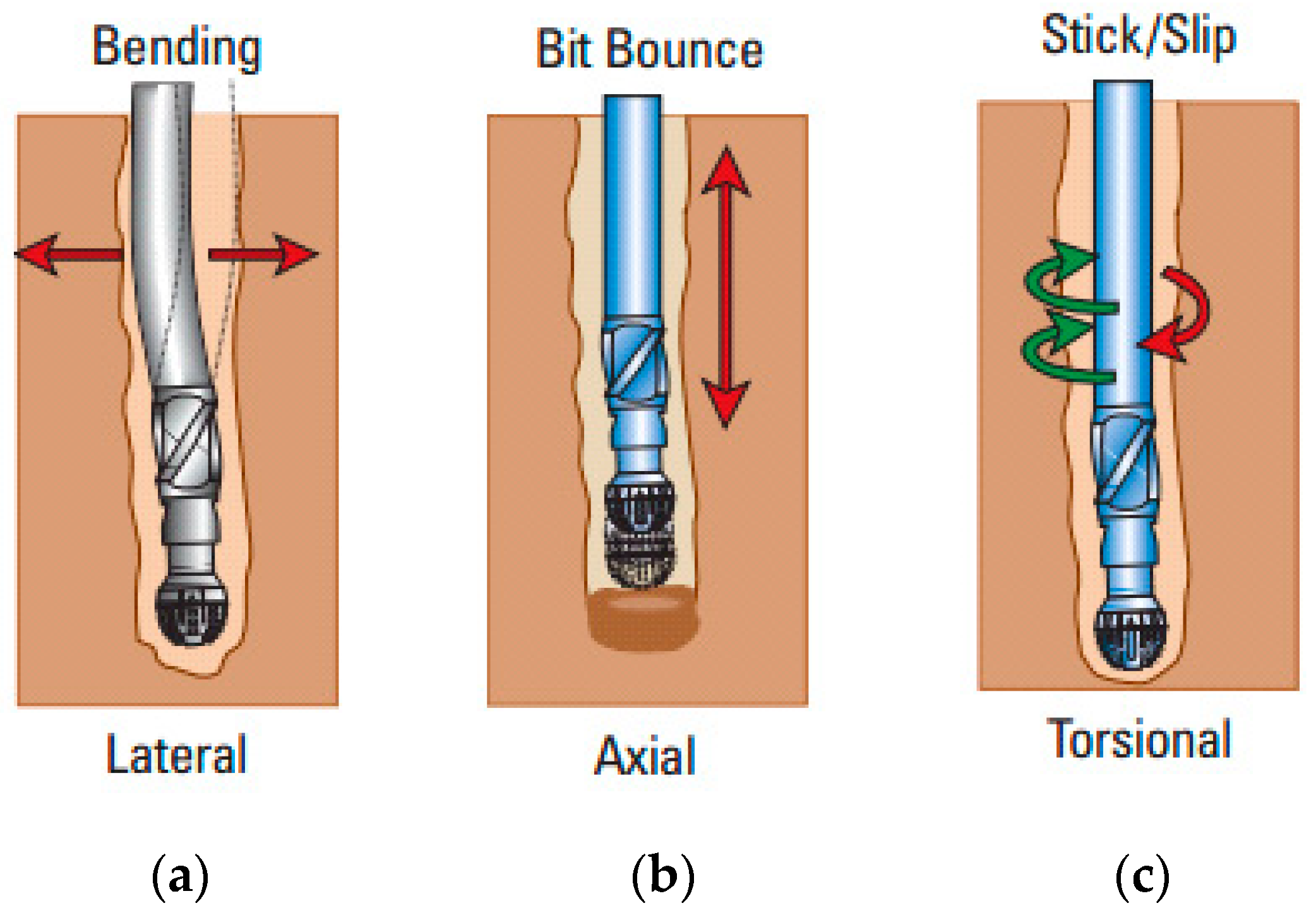
Lateral vibrations arise when the drill bit, more precisely the BHA, rotates eccentrically around the well axis. Inertia forces that attempt to destabilize the drillstring cause the axis deviation of rotation (
Figure 4a). The phenomenon generated by this type of vibration is called ‘whirling’, it could manifest on BHA or on drill bit. The BHA may receive an excitation (perturbation that triggers the whirling) from the bit, as a result of lateral and perpendicular forces to the axis of rotation. According to oil and gas companies, the major problems that are caused by this phenomenon are: widening the hole due to the irregular bit rotation, reduction in drill pipe virtual life due to cyclic variations in vibrations, the instantaneous rupture of drillstring (appearance of micro-cracks which increase as the phenomenon occurs) and severe contacts with the borehole walls [
17]. According to the direction in which it occurs, the whirling phenomenon can be divided into two main types: the first type is ‘forward whirl’, in which the precession of the drillstring turns in the same direction as the bit rotation; the second type is ‘backward whirl’, which means that the precession takes place in the opposite direction of rotation. Besides, in the third type, the precession has a random direction.
4.2. Axial Vibrations
Axial vibrations generate a phenomenon called ‘bit-bounce’, which means that the drill bit loses contact with the formation and undergoes rebounds in the direction of penetration (
Figure 4b). This type of vibration is generally detected in tri-cone bits; severe problems have been recorded for this bit. For example, slowing down the penetration rate can create failure of the bit and the BHA components. For shallow depths, these vibrations can affect even surface equipment (top drive bounce). In such case, the detection of this phenomenon is very easy. Drilling mud is also influenced by axial vibrations (pressure fluctuation). For deep wells, axial oscillations are damped, which then prevent their propagation to the surface. For PDC bits, these vibrations have been classified as secondary vibrations [
22].
4.3. Torsional Vibrations
Torsional vibrations are considered as the most dangerous vibrations to which the drillstring is vulnerable to. The phenomenon responsible for the regeneration of these vibrations is known as ‘stick-slip’ (
Figure 4c). Stick-slip occurs when the drill bit is frictionally engaged with the formation in a non-linear manner; the non-linearity causes the bit to switch between two phases; an adhesion phase and a sliding phase. Therefore, the velocity value undergoes intense variations; the severity of this phenomenon can go as far as completely stopping the drilling process, wherein, rotational speed variations are considered a strong indicator of stick-slip [
23,
24].
Recordings from MWD (measurement while drilling) of well-1 located in Algerian hydrocarbons field indicate that the rotational speeds at the bit are irregular, more precisely; the curve representing this speed contains peaks and valleys (
Figure 5). The bit speed corresponding to a peak is six times the value of the speed measured at the surface. Also, the speed corresponding to stuck phase can reach the value zero, which means that the bit is completely blocked; contrary to the surface where nothing is indicated. The duration of the stuck phase varies from 1 s up to 5 s. While the bit is stuck at the bottom of the borehole, the top drive system continues to rotate at a constant velocity; this implies that the drillstring is twisting. This torsion makes the pipes to store elastic energy, however, above a certain quantity, the torque applied on the bit becomes greater than the resisting torque (static torque), which consequently releases the bit, and the cycle is repeated again.
5. Stick-Slip Vibrations
The purpose of the model introduced in this paper is to study the dynamic behavior of the drillstring in an operational mode. This model combines the mechanical response of drillstring to torsional vibrations, and the bit–rock interaction. Based on Navarro-Lopez [
11], the drillstring is divided into three main parts: (1) top rotating system, (2) drill pipes, and (3) BHA. Each element is represented in the form of a disk of mass (
) and inertia (
); the disks are connected to each other by springs with a torsional stiffness (
) and a viscous damping coefficient (
).
Figure 3 shows the drillstring as a torsion pendulum driven by the top drive.
The interaction of the drilling mud with the drillstring can be simplified in the form of viscous damping
and
along the drill pipes and the BHA, respectively. It is assumed that the top drive rotates with an initial velocity
and provides a torque Tm (with neglecting the damping and frictional torques at the top drive). According to the fundamental principle of the rotational dynamics
L is angular momentum and
M is dynamic moment of external forces
is unit vector. Substituting (3) in (2), Equation (4) is obtained.
Taking into account the viscous forces and the rigidity of elements, the equation of motion becomes
C is viscous damping,
k is torsional stiffness,
i is current element,
i + 1 is next element. By applying Equation (5), equations of motion for three elements are given in (6)
is the torque on the bit,
approximates the influence of the drilling mud on the bit,
is the non-linear friction torque due to bit-rock contact interaction, it is given in (7).
is the weight on the bit,
is the bit radius,
represents the rotational direction; and
is the bit dry friction, which follows the Karnopp friction model, and it is given in (8).
is the static friction coefficient,
is the Coulomb friction coefficient,
and
are constants verifying the following assumptions:
and
, to simplify calculation, it is assumed that
λ =
. The sign function is defined in (9).
In the next section, simulation results will be presented with several scenarios, including input torque variation, change in WOB and bit radius variation. The simulations were carried out using the MATLAB/Simulink R2012a (7.14.0.739). Simulink block consists of three main parts, each part represents one element with one degree of freedom, and the three elements are strongly coupled to each other. Six integrator blocks are used, two for each part. The blocks are connected to each other in order to reproduce the nonlinear equations. Other blocks are added to represent the different coefficients and the different summation and multiplication operations.
5.1. Stick-Slip Vibration Severity
In this part, the severity of stick-slip vibrations has been analyzed, where their relationship with input torque, WOB, and bit diameter (Di) are investigated. These parameter variations indicate the field specifications, i.e., the diameter variation represents the change of drilling phase.
5.2. Input Torque Variation
The torque imposed by the viscous fluid (Tar) at the top drive is neglected, the input torque is represented as a step function with Umin = 5000 Nm and Umax =10000 Nm.
Figure 6 shows torque on bit (Tob) variations caused by the input torque monitoring.
5.3. Weight on Bit Variation
The weight on bit model used in this part of simulation is inspired from the model proposed by Yigit and Christoforou [
25], and Khulief et al. [
26]. Weight on bit formula is given in (10).
is the frequency of variations,
is the depth of cut for a rotation of the tool, and
W0 is the initial value of WOB. The frequency
depends on the depth of cut
and
is the ROP (rate of penetration), which is given in (11).
Figure 7 shows an example of WOB variation as a function of time. The initial value of WOB is W
0 = 170,000N.
In
Section 6, four parameters will be varied: D
i to indicate the changes in the drilling phase, WOB to show the influence of the weight on the appearance of torsional vibrations, λ to simulate the decay factor, and finally the input torque. The coefficients C
t, C
tb, J
r, J
p, J
b, k
t, and k
tb have constant values for all scenarios. The variation of these parameters gives an idea on how to reduce and attenuate the stick-slip vibrations, noting that the manipulation of input torque and WOB is the first solution to use when stick-slip is observed.
6. Scenarios and Simulation Results
6.1. First Scenario: D1 = 0.6604 m; λ = 0.4; W0 = 40,000 N
In the first scenario, the stick-slip appears during the whole simulation time, the bit is almost stuck in the time interval (25, 30 s) (
Figure 8a). This time corresponds to low values of input torque (
Figure 8b). Indeed, low values of top torque increase the sticking phase time. For high values of input torque, the angular velocity of bit becomes greater than the top velocity, the period of sticking phase decreases and significant torsional oscillations are observed. Moreover, stick-slip vibrations have slowed down the rate of penetration (
Figure 8c).
6.2. Second Scenario: D2 = 0.4064 m; λ = 0.4; W0 = 75,000 N
In the second scenario, the bit diameter has been manipulated, and an increase in weight is considered.
Figure 9a shows the angular velocities of drill pipes, top drive and drill bit. Despite the change in diameter, stick-slip vibrations do not disappear for this drilling section. The increase in the weight on the bit causes an increase in the torque on the bit (
Figure 9b), wherein the severity of stick-slip is more apparent than the first scenario, this is due to the influence of weight on bit. Since the rate of penetration depends on the angular velocity of the bit, the curve shape of ROP has changed by the same way as the angular velocity curve (
Figure 9c).
6.3. Third Scenario: D3 = 0.3116 m; λ = 0.9; W0 = 85,000 N
In the third scenario, large amplitude velocity oscillations have been observed (
Figure 10a), the bit velocity oscillates without registering a long period of bit sticking. The combined value of bit diameter and input torque eliminates the sticking period, but oscillations still exist. The torque on bit has a smooth curve (
Figure 10b).
6.4. Fourth Scenario: D4 = 0.2159 m; λ = 0.4 W0 = 122,000 N
In the fourth scenario, the torque values have been reduced in the time interval [12, 25s] from Umax = 10,000 Nm to Umin = 5000 Nm (
Figure 11b). This reduction causes bit velocity oscillations of large amplitudes and a reduction in the time of the sticking phase (
Figure 11a). Once the input torque value reaches Umin, the drill bit gets stuck again for 5 sec. Furthermore, as soon as the top torque returns to its value Umax, the bit starts to run, and the value oscillations reproduce again. Certainly, the input torque affects the rate of penetration, high values of ROP correspond to an input torque value equals to Umin = 5000 Nm (
Figure 11c).
6.5. Fifth Scenario: D5 = 0.1524 m; λ = 0.09; W0 = 170,000 N
In the fifth scenario, the bit is stuck during the time interval (10, 35s), as a result, an increase in the input torque value is applied. In spite of this, the bit remains stuck (
Figure 12a). This problem can be seen as a result of the application of a high WOB value. WOB also influences the rate of penetration (
Figure 12c). In this case, and in order to eliminate the stick-slip phenomenon, the input torque should be greater than Umax = 10,000 Nm or a decrease of the WOB value has to be taken.
7. Discussion
As the parameter λ decreases, the severity of stick-slip increases (
Figure 12a), it should be noted that λ characterizes the speed of the decrease of the TOB. So, it is obvious that for small values, the torque (TOB) will last for long time before decreasing (
Figure 12b), this consequently influences the stick-slip phenomenon. The variation in the value of the radius does not mitigate the stick-slip phenomenon; however, it influences the severity of stick-slip (make it less strong). The stick-slip is very rigorous when using a motor torque having a value Umin = 5000 Nm. The stick-slip disappears when using a motor torque with a value Umax =10,000 Nm, but there would be a risk of premature and severe wear due to large amplitude oscillations.
Destructive downhole vibrations have been shown as the probable culprit of many drill bit and drillstring failures. The most effective way to control vibration has proven to be modifying the operating parameters (RPM/WOB) [
27,
28,
29].
The optimal values to eliminate the torsional vibrations are obtained in the third case, with WOB = 85,000 N, U = 7500 Nm, and
. Based on these data, the relationship in (12) is proposed and a threshold value is found.
To mitigate the stick-slip phenomenon by eliminating torsional vibrations, the proposed mathematical relationship should be respected, and the threshold should not be exceeded. However, due to the delay of manipulation of these parameters and the fast dynamic vibrations, many deformations can occur [
30], observations in well-1 had confirmed this fact as it is explained in detail in
Section 8.
8. Case Study of Well-1
8.1. Drill Bit Deformations
Large deformations were observed to the nose cutters of bit during the drilling of Well-1 in Algerian hydrocarbons field. Data collected from the ‘BlackBox’ vibration tool show the appearance of three types of vibrations. Moreover, the damages are mainly located in the nose cutters (wear, grabbing, deformations, etc.) [
31]. These damages are essentially due to the torsional vibrations which cause the bit to stop and then release simultaneously. This periodic cycle causes the bit and the geological formation to come into contact at very high speeds, thence, small damages or cracks take place. As the cycle repeats with high frequency, these small damages become significant and important, and as a result, large deformations appear as shown in
Figure 13. Simulation results have shown the appearance of wide fluctuations in bit speed, which are better suited to field data.
8.2. Influnce of (WOB/ROP)
BlackBox
TM shows the values of WOB and ROP during the drilling operation, the difference between these data and simulation is that the influence of geological layer is included in the recorded data, while in the simulation this parameter has been manipulated [
31]. Both data collected (
Figure 14) and simulation results (
Figure 12c) show the influence of WOB on the rate of penetration.
9. Conclusions
The main objective of this study was to investigate and analyze the damages that appeared in the drill bit of an operating drilling system located in an Algerian hydrocarbons field. For that reason, three-DOF model has been used in this paper to study torsional vibrations of drillstring. Five scenarios with various parameters were presented and simulated using the MATLAB/Simulink R2012a (7.14.0.739). Stick-slip phenomenon was observed in the bit for all scenarios. The influence of input torque, weight on bit, decaying factor, and bit radius were discussed and analyzed. In order to verify the accuracy of simulation, a comparison with field data was presented. The obtained results demonstrate that the stick-slip vibrations are very damaging to the drill bit even if it is controlled by parametric variation because the delay between the appearance of such phenomenon and the intervention is considerable, thus, it creates minor damage. Moreover, the repetition of these speed variation anomalies in the drill bit during the drilling phase turns minor damage into considerable grabbing, wear, and deformation in the studied well. Moreover, the location of these deformations was in the nose cutters, which can be considered as signature of such type of vibrations. Thus, it is highly recommended to apply latest dynamic preventive maintenance of drilling equipment to prevent them from hazards of stick-slip high amplitude-high frequency vibrations.
Author Contributions
Methodology, S.B. and M.Z.D.; software, I.K.; validation, I.K. and M.Z.D.; formal analysis, S.B. and K.F.T.; investigation, S.B. and I.K.; resources, M.Z.D.; data curation, K.F.T.; writing—original draft preparation, I.K.; writing—review and editing, M.Z.D. and I.K.; visualization, K.F.T.; supervision, S.B.; project administration, S.B. All authors have read and agreed to the published version of the manuscript.
Funding
This research received no external funding.
Acknowledgments
The authors of this paper would like to express their sincere thanks to the reviewers for acceptance to review this paper.
Conflicts of Interest
The authors declare no conflict of interest.
Nomenclature
| I | Moment of inertia (Kg/m2) |
| Φ | Angular displacement (Radians) |
| Ω0 | Initial velocity (Rad/s) |
| Tb | Torque generated by frictional forces (N·m) |
| C | Damping coefficient (N·m/s) |
| K | Torsional stiffness (N·m/rad) |
| Jr | Inertia of top drive (Kg·m2) |
| Jp | Inertia of drill pipes (Kg·m2) |
| Jb | Inertia of BHA plus bit (Kg·m2) |
| Ct | Damping coefficient along drill pipes |
| Ctb | Damping coefficient along BHA |
| kt | Torsional stiffness of drill pipes (N·m/s) |
| ktb | Torsional stiffness of BHA (N·m/rad) |
| L | Angular momentum (Kg·m2/s) |
| M | Dynamic moment (Kg·m/s) |
| θr | Angular displacement of top drive (Radians) |
| θp | Angular displacement of drill pipes (Radians) |
| θb | Angular displacement of bit (Radians) |
| Tb() | Torque on the bit (N·m) |
| Tab() | Influence of the drilling mud on the bit (N·m) |
| Tfb() | Non-linear friction torque (N·m) |
| µb() | Bit dry friction coefficient (dimensionless) |
| µcb | Coulomb friction coefficient (dimensionless) |
| µsb | Static friction coefficient (dimensionless) |
| λ | Decay rate of friction torque (dimensionless) |
| Sign() | sign function (dimensionless) |
| F | Frequency of variation (Hz) |
| x0 | Cut of depth (m) |
| W0 | Initial weight on bit (tones) |
References
- Dubinsky, V.S.; Baecker, D.R. An Interactive Drilling Dynamics Simulator for Drilling Optimization and Training. In Proceedings of the SPE Annual Technical Conference and Exhibition, New Orleans, LA, USA, 27–30 September 1998. [Google Scholar]
- Khulief, Y.A.; Al-Naser, H. Finite element dynamic analysis of drillstrings. Finite Elem. Anal. Des. 2005, 41, 1270–1288. [Google Scholar] [CrossRef]
- Yigit, A.; Christoforou, A.P. Coupled Torsional and Bending Vibrations of Actively Controlled Drillstrings. J. Sound Vib. 2000, 234, 67–83. [Google Scholar] [CrossRef]
- Chen, S.L.; Blackwood, K.; Lamine, E. Field investigation of the effects of stick-slip, lateral and whirl vibrations on roller cone bit performance. SPE Drill. Complet. 2002, 17, 15–20. [Google Scholar] [CrossRef]
- Lin, Y.Q.; Wang, Y.H. Stick slip vibration of drill strings. J. Manuf. Sci. Eng. 1991, 113, 38–43. [Google Scholar] [CrossRef]
- Kyllingstad, A.; Halsey, G.W. A study of slip/stick motion of the bit. SPE Drill. Eng. 1988, 3, 369–373. [Google Scholar] [CrossRef]
- Qiu, H.; Yang, J.; Butt, S. Investigation on bit stick-slip vibration with random friction coefficients. J. Pet. Sci. Eng. 2018, 164, 127–139. [Google Scholar] [CrossRef]
- Patil, P.A.; Teodoriu, C. Model development of torsional drillstring an investigating parametrically the stick-slips influencing factors. J. Energy Resour. Technol. 2013, 135, 013103. [Google Scholar] [CrossRef]
- Navarro-Lopez, E.M.; Cortes, D. Avoiding harmful oscillations in a drillstring through dynamical analysis. J. Sound Vib. 2007, 307, 152–171. [Google Scholar] [CrossRef]
- Silveira, M.; Wiercigroch, M. Low dimensional models for stick-slip vibration of drillstrings. J. Phys. Conf. Ser. 2009, 181, 1–8. [Google Scholar] [CrossRef]
- Navarro-Lopez, E.M. An alternative characterization of bit-sticking phenomena in a multi-degree-of-freedom controlled drillstring. J. Nonlinear Anal. Real World Appl. 2009, 10, 3162–3174. [Google Scholar] [CrossRef]
- Saldivar, B.; Mondié, S.; Loiseau, J.J.; Vladimir, R. Stick-slip oscillations in oilwell drillstrings: Distributed parameter and neutral type retarded model approaches. In Proceedings of the 18th IFAC World Congress, Milano, Italy, 28 August–2 September 2011. [Google Scholar]
- Bhandari, G.; Arzaghi, J.; Abbassi, E.; Garaniya, R. Risk-based maintenance of offshore managed pressure drilling (MPD) operation. J. Pet. Sci. Eng. 2017. [Google Scholar] [CrossRef]
- Riane, R.; Kidouche, M.; Doghmane, M.Z.; Illoul, R. Modeling of torsional vibrations nonlinear dynamic in drill-string by using PI-observer. In Proceedings of the Fourth International Conference on Electrical Engineering and Control Applications ICEECA, Constantine, Algerian, 17–19 December 2019. [Google Scholar]
- Zhang, Y.; Zhang, M.; Wang, Y.; Xie, L. Fatigue Life Analysis of Ball Bearings and a Shaft System Considering the Combined Bearing Preload and Angular Misalignment. Appl. Sci. 2020, 10, 2750. [Google Scholar] [CrossRef] [Green Version]
- Riane, R.; Kidouche, M.; Illoul, R.; Doghmane, M.Z. Unknown Resistive Torque Estimation of a Rotary Drilling System Based on Kalman Filter. IETE J. Res. 2020. [Google Scholar] [CrossRef]
- Wang, Y.; Qian, C.; Kong, L.; Zhou, Q.; Gong, J. Design Optimization for the Thin-Walled Joint Thread of a Coring Tool Used for Deep Boreholes. Appl. Sci. 2020, 10, 2669. [Google Scholar] [CrossRef] [Green Version]
- Bailey, J.R.; Biediger, E.; Gupta, V.; Ertas, D.; Elks, W.C.; Dupriest, F.E. Drilling Vibrations Modeling and Field Validation. In Proceedings of the IADC/SPE Drilling Conference, Orlando, FL, USA, 4–6 March 2008. [Google Scholar]
- Ghasemloonia, A.; Rideout, D.G.; Butt, S.D. A review of drill string vibration modeling and suppression methods. J. Pet. Sci. Eng. 2015, 131, 150–164. [Google Scholar] [CrossRef]
- Langeveld, C.J. PDC bit dynamics. In Proceedings of the SPE/1ADC Drilling Conference, New Orleans, LA, USA, 18–21 February 1992. [Google Scholar]
- Jardine, S.; Malone, D.; Sheppard, M. Putting dampers on drilling’s bad vibrations. Oilfield Rev. 1994, 6, 15–20. [Google Scholar]
- Pastusek, P.; Sullivan, E.; Harris, T. Development and utilization of a bit-based data-acquisition system in hard-rock PDC applications. In Proceedings of the SPE/IADC Drilling Conference, Amsterdam, The Netherlands, 20–22 February 2007. [Google Scholar]
- Daly, J.E.; Pastusek, P.E. Drill bit having a failure indicator. U.S. Patent US4610313A, 9 September 1986. [Google Scholar]
- Ren, Y.; Wang, N.; Jiang, J.; Zhu, J.; Song, G.; Chen, X. The Application of Downhole Vibration Factor in Drilling Tool Reliability Big Data Analytics—A Review. ASCE-ASME J. Risk Uncertain. Eng. Syst. Part B Mech. Eng. 2019, 5, 010801. [Google Scholar] [CrossRef] [Green Version]
- Yigit, A.S.; Christoforou, A.P. Coupled torsional and bending vibrations of drillstrings subject to impact with friction. J. Sound Vib. 1998, 215, 167–181. [Google Scholar] [CrossRef]
- Khulief, Y.A.; Al-Sulaiman, F.A.; Bashmal, S. Vibration analysis of drillstrings with self-excited stick slip oscillations. J. Sound Vib. 2007, 299, 540–558. [Google Scholar] [CrossRef]
- Doghmane, M.Z. Optimal Decentralized Control Design with Overlapping Structure. Ph.D. Thesis, University M’hamed Bougara of Boumerdes, Boumerdes, Algeria, 2011. [Google Scholar]
- Doghmane, M.Z.; Kidouche, M.; Habbi, H. A new decomposition strategy approach applied for a multi-stage printing system control optimization. In Proceedings of the IEEE 4th International Conference on Electrical Engineering, Boumerdes, Algeria, 13–15 December 2015. [Google Scholar] [CrossRef]
- Doghmane, M.Z.; Kidouche, M. Decentralized controller Robustness improvement using longitudinal overlapping decomposition—Application to web winding system. Elektron. Elektrotech. 2018, 24, 10–18. [Google Scholar] [CrossRef]
- Huang, J.; Zhang, A.; Sun, H.; Shi, S.; Li, H.; Wen, B. Bifurcation and Stability Analyses on Stick-Slip Vibrations of Deep Hole Drilling with State-Dependent Delay. Appl. Sci. 2018, 8, 758. [Google Scholar] [CrossRef] [Green Version]
- Grant, C. BlackBoxTM Dynamics Analysis Report; Internal Report; Sonatrach-Algeria: Algiers, Algeria, 2016. [Google Scholar]
Figure 1.
A general schema of typical rotary drilling system.
Figure 1.
A general schema of typical rotary drilling system.
Figure 2.
Types of drill bit: (a) bit anatomy, (b) matrix body of PDC bit, (c) natural diamond tricone bit.
Figure 2.
Types of drill bit: (a) bit anatomy, (b) matrix body of PDC bit, (c) natural diamond tricone bit.
Figure 3.
Three elements proxy model of rotary drilling system.
Figure 3.
Three elements proxy model of rotary drilling system.
Figure 4.
Types of vibrations: (a) axial, (b) lateral, (c) torsional.
Figure 4.
Types of vibrations: (a) axial, (b) lateral, (c) torsional.
Figure 5.
Measured vibration using BlackBox in Well-1.
Figure 5.
Measured vibration using BlackBox in Well-1.
Figure 6.
Output torques responses to input torque variations: (a) Input torque, (b) Tob.
Figure 6.
Output torques responses to input torque variations: (a) Input torque, (b) Tob.
Figure 7.
Weight on bit variation.
Figure 7.
Weight on bit variation.
Figure 8.
Results of system responses for first scenario: (a) angular velocities, (b) Tob, (c) ROP.
Figure 8.
Results of system responses for first scenario: (a) angular velocities, (b) Tob, (c) ROP.
Figure 9.
Results of system responses for second scenario: (a) angular velocities, (b) Tob, (c) ROP.
Figure 9.
Results of system responses for second scenario: (a) angular velocities, (b) Tob, (c) ROP.
Figure 10.
Results of system responses for third scenario: (a) angular velocities, (b) Tob, (c) ROP.
Figure 10.
Results of system responses for third scenario: (a) angular velocities, (b) Tob, (c) ROP.
Figure 11.
Results of system responses for fourth scenario: (a) angular velocities, (b) Tob, (c) ROP.
Figure 11.
Results of system responses for fourth scenario: (a) angular velocities, (b) Tob, (c) ROP.
Figure 12.
Results of system responses for fifth scenario: (a) angular velocities, (b) Tob, (c) ROP.
Figure 12.
Results of system responses for fifth scenario: (a) angular velocities, (b) Tob, (c) ROP.
Figure 13.
Drill bit damage due to stick-slip vibrations in Algerian hydrocarbons.
Figure 13.
Drill bit damage due to stick-slip vibrations in Algerian hydrocarbons.
Figure 14.
Data collected from BlackBoxTM of WOB and ROP in Well-1.
Figure 14.
Data collected from BlackBoxTM of WOB and ROP in Well-1.
© 2020 by the authors. Licensee MDPI, Basel, Switzerland. This article is an open access article distributed under the terms and conditions of the Creative Commons Attribution (CC BY) license (http://creativecommons.org/licenses/by/4.0/).


