Article

Study on the Vibration Active Control of Three-Support Shafting with Smart Spring While Accelerating over the Critical Speed

National Key Laboratory of Science and Technology on Helicopter Transmission, Nanjing University of Aeronautics and Astronautics, Nanjing 210016, China
*
Author to whom correspondence should be addressed.
Appl. Sci. 2020, 10(17), 6100; https://doi.org/10.3390/app10176100
Submission received: 30 July 2020 / Revised: 30 August 2020 / Accepted: 31 August 2020 / Published: 2 September 2020
(This article belongs to the Special Issue Modelling and Control of Mechatronic and Robotic Systems)

Abstract

:
Smart Spring is a kind of active vibration control device based on piezoelectric material, which can effectively suppress the vibration of the shaft system in an over-critical state, and the selection of control strategy has great influence on the vibration reduction effect of the Smart Spring. In this paper, the authors investigate the control of the over-critical vibration of the transmission shaft system with Smart Spring, based on the ADAMS and MATLAB joint simulation method. Firstly, the joint simulation model of three-support shafting with Smart Spring is established, and the over-critical speed simulation analysis of the three-support shafting under the fixed control force of the Smart Spring is carried out. The simulation results show that the maximum vibration reduction rate is 71.6%. The accuracy of the joint simulation model is verified by the experiment of the three-support shafting subcritical vibration control. On this basis, a function control force vibration control strategy with time-varying control force is proposed. By analyzing the axis orbit of the shafting, the optimal fixed control force at different speeds is obtained, the control force function is determined by polynomial fitting, and the shafting critical crossing simulation under the function control force is carried out. The simulation results show that the displacement response of the shafting under the function control force is less than that under the fixed control force in the whole speed range.

1. Introduction

The multi-support shafting is a typical rotor system [1]. When the shafting is accelerated and over-critical, the vibration is intensified, which restricts the performance of the tail drive system. Excessive vibration may lead to the failure of system components, reduce the service life of equipment, waste energy, generate excessive noise, damage the health of staff, and even cause major accidents resulting in heavy property loss and casualties. Therefore, it is necessary to suppress the bending vibration of the shafting in the over-critical state [2]. At present, vibration control methods include mainly the following [3]: dynamic balance, passive control, and active control. Active control vibration reduction technology attenuates vibration by actively applying control force. The commonly used active shock absorbers are electromagnetic damper [4], squeeze film damper [5], magnetorheological damper, electrorheological damper, and piezoelectric actuator. Among them, the piezoelectric actuator has the advantages of simple structure, light weight, high control accuracy, and fast response; it has a good application prospect in the field of vibration control, but its actuation displacement is small. A.B. Palazzolo et al. were the first to study the vibration control of the piezoelectric actuator in a rotor system. By controlling the output force of the piezoelectric actuator to change the supporting parameters of the bearing pedestal, the vibration of the rotor was reduced [6,7]. The advantages and disadvantages of active damping feedback control and active stiffness feedback control were analyzed. The experimental results showed that the speed feedback control method can effectively suppress the rotor shaft system [8]. The Smart Spring [9] is an active vibration damping device based on a piezoelectric actuator, which is composed of a main support and an auxiliary support. The main support is the elastic support of shafting itself. By controlling the actuating force of the piezoelectric ceramic actuator on the auxiliary support, positive pressure is generated between friction elements on the main support and the auxiliary support, and vibration energy is consumed through dry friction between friction plates.
According to the research on the vibration reduction technology of Smart Spring, Nitzsche of Carlton University of Canada has done a lot of work on the application of the Smart Spring to helicopter blade vibration reduction. In 2012, Nitzsche et al. applied a set of semi-active Smart Spring systems to the vibration reduction of a helicopter rotor system. The control scheme selected the state switching, and the vibration reduction performance of the Smart Spring was verified by experiments [10]. In 2013, Nitzsche et al. improved the active variable pitch pull rod APL (Active pitch link) of the damping device and verified the damping performance of the improved APL in the rotating tower test. The results showed that the APL effectively attenuated the vibration response of the blade and reduced the transmission force [11]. Other scholars on Nitzsche’s team have also done a lot of work on the application of Smart Springs to helicopter blade damping. Afagh et al. placed the Smart Spring mechanism on the load transfer path of the blade to achieve the purpose of vibration reduction and studied the stability of the blade in the Elastohydrodynamic state [12]. Coppotelli et al. studied the dynamic characteristics of the Smart Spring installed on the blade of a non-rotating helicopter, analyzed the influence of the Smart Spring on the modal characteristics, and finally established the finite element model of the blade [13]. Some scholars from the Aeronautical Research Institute of Canada also studied the Smart Spring damping technology. Chen Yong et al. established a mathematical model under harmonic excitation and designed an adaptive notch algorithm to reduce vibration on the DSP (Digital Signal Processor) platform. Wind tunnel tests were carried out to verify the damping effect of the Smart Spring [14]. Wickramasinghe et al. proved the ability of the Smart Spring to control the dynamic impedance characteristics of the structure through experimental research, and the vibration reduction performance was proved by the wind tunnel test [15]. Grewal et al. designed a control scheme to make the stiffness of the Smart Spring device change continuously and compared it with the control effect of the state switching control algorithm [16]. To sum up, the research into Smart Spring has been mainly on the aspect of torsional vibration control of the helicopter blade, and the research into Smart Spring vibration reduction applied to multi-support shafting has been mainly dynamic modeling and characteristic analysis. Ni De [17] carried out dynamic analysis on the shaft system with Smart Spring, studied the design method of intelligent spring parameters, and analyzed the vibration control effect of the intelligent spring in multi-support shafting. Peng Bo [18] made a preliminary exploration of the multi-span shafting vibration reduction of the intelligent spring, established the multi-span shafting dynamic model of the intelligent spring, analyzed the influence of intelligent spring control force and its parameters on vibration reduction performance, and optimized the parameters of the intelligent spring with a genetic algorithm.
At present, there is a lack of theoretical guidance and related experimental verification for the research on using Smart Spring to reduce the vibration of tail drive shafting. The application of Smart Spring to the vibration reduction of the tail drive shaft system needs further research. In this paper, the control strategy of exerting fixed control force and function control force is put forward. By using the ADAMS and MATLAB joint simulation method, the research on over-critical vibration control of three-support shafting with Smart Spring support is carried out, and the accuracy of the joint simulation method is verified by experiments.

2. Research on Vibration Reduction of the Shaft System with Fixed Control Force Applied by Smart Spring

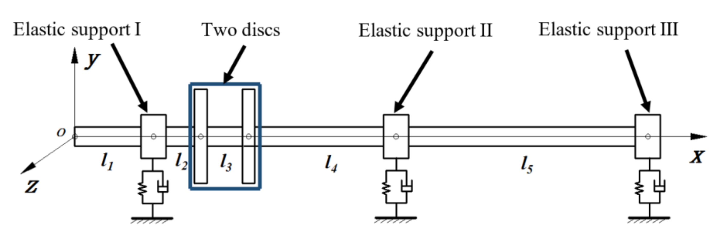
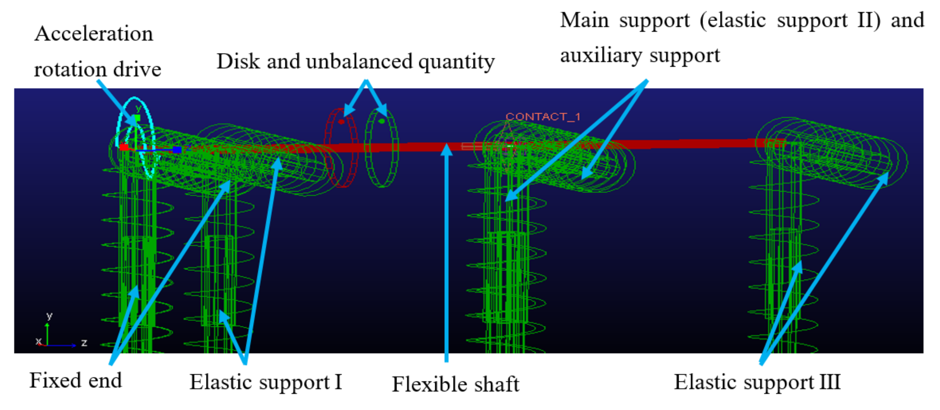
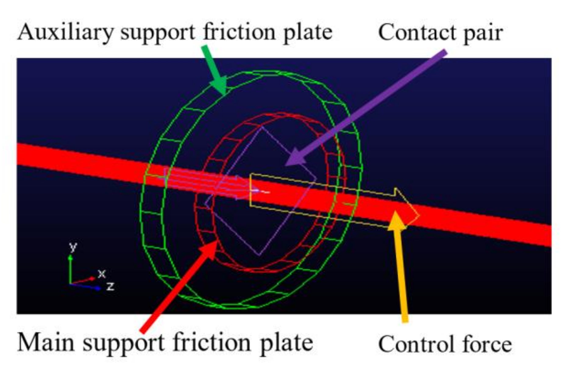
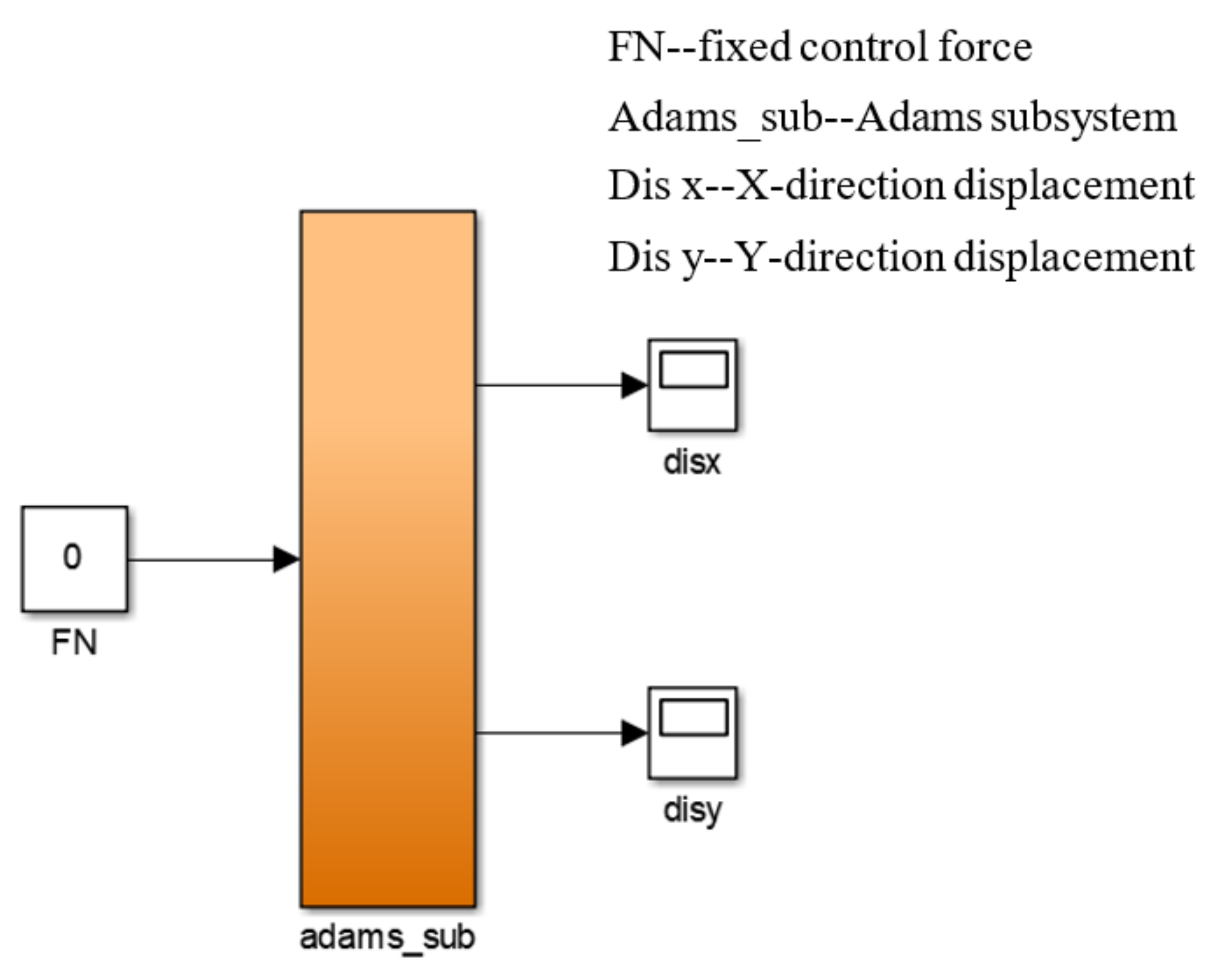
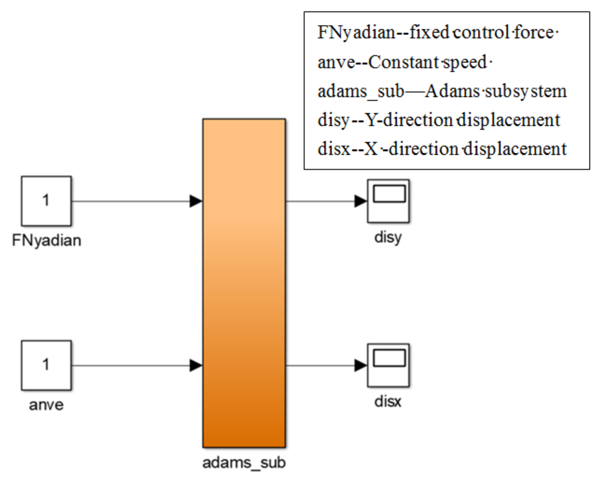
2.1. Establishment of Joint Simulation Model of Three-Support Shafting Based on ADAMS and MATLAB

The double-disk three-support shafting with Smart Spring was taken as the research object, as shown in Figure 1. The three-support shafting consisted of motor, diaphragm coupling, transmission shaft, rigid disk, elastic support, and Smart Spring pair support. The Smart Spring consisted of basic support, auxiliary support, and a piezoelectric ceramic actuator (PZTA). The simplified principle of Smart Spring support is shown in Figure 2a. The radial stiffness and damping of the basic support are k and c, and the radial stiffness and damping of the active support are k′ and c′, m′ is the equivalent mass of the PZTA and other components connected with the active support. Fd is the sliding friction force caused by the control force Nt between the friction pair of the basic support and the auxiliary support. The lower end of the Smart Spring support was fixed on the foundation, and the upper end bore the support reaction force Ft from the shaft section. The radial displacement of the main support is u and that of the auxiliary support is u′. There was an initial clearance between the main support and the auxiliary support. The structure diagram of Smart Spring is shown in Figure 2b.
The shaft system was a typical variable cross-section continuous rotor system with disk rotor, shaft sleeve, and coupling. Based on the finite element method, the variable cross-section of the three-support shafting was truncated and discretized. As shown in Figure 3, taking no account of the influence of the coupling on the bending vibration of the shaft system in discrete processing, the three-support shafting was discretized into disk, shaft section, and bearing seat, in turn, while the two sections of shaft were regarded as a single optical axis. The dynamic model of three-support shafting with double disks was established. The allowable degrees of freedom in the model were x-axis rotation and the translation of Y and Z. The basic parameters are shown in Table 1.
According to the dynamic model of three-support shafting, the virtual prototype model of shafting was established in ADAMS simulation software, as shown in Figure 4. Combined with the actual working state of the shafting, the constraint conditions of the virtual prototype model of the shafting were set. The eccentricity was added to the flexible shaft to simulate the imbalance of the shaft, and the spring with stiffness and damping was used to simulate the elastic support. A rotation drive was added to the left end face of the flexible shaft. The rotation drive adopted the mode of constant acceleration, and the acceleration was set as 20π rad/s2. In order to realize the contact and action between the friction disks of the main support and the auxiliary support of the Smart Spring, as shown in Figure 5, two friction disks were established on the virtual prototype model to the equivalent mass of the main and auxiliary supports, and the control force and contact pair were added to the friction disk. Furthermore, the friction force was linearized, which was equal to the product of the friction coefficient and control force after linearization.
ADAMS software focuses on the mechanical dynamics simulation, while MATLAB focuses on the control system simulation. Using the ADAMS and MATLAB joint simulation method, based on the ADAMS/control module, we imported the mechanical system simulation model from ADAMS directly to MATLAB without tedious derivation and the listing of a large number of equations to describe the law of the control system, which greatly simplified the workload of modeling. At the same time, we added the complex control directly to the ADAMS model, which can simulate the whole system at one time, and, even if there are problems, they can be easily solved. The ADAMS virtual prototype model was imported into MATLAB, and the open-loop control joint simulation model of double-disk shafting was obtained, as shown in Figure 6. The joint simulation model consisted of the ADAMS module, input module, and output module. The input module was the control force of the actuator, and the control force was input into ADAMS module. The two output modules were the displacement responses in X direction and Y direction at the middle position of the shafting.

2.2. Analysis of Simulation Results of Shafting Over-Critical

The mid-point of support I and support II was selected as the measuring point, and fixed control forces of 100 N, 200 N, 300 N, 425 N, 800 N, and 1000 N were applied respectively to simulate the shaft system passing through the critical point, and the displacement response at the measuring point was obtained. Due to the isotropy of the rotor, the shafting had similar displacement response curves in X and Y directions. Therefore, the displacement response curves in the Y direction were selected for analysis.
Figure 7 shows the over-critical bending vibration response of a double-disk three-support shafting with Smart Spring support under different fixed control forces. It can be seen from Figure 7 that the application of fixed control force can significantly suppress the critical response peak value and the critical speed shifts to the right. When the fixed control force was less than 200 N, the vibration response decreased in the whole speed range. When t < 6 s, i.e., the speed was lower than 3600 r/min, the vibration could be attenuated by applying 0–1000 N fixed control force. However, when t > 7 s, i.e., the rotating speed was greater than 4200 r/min, and the fixed control force was greater than 200 N, the vibration was increased by applying the fixed control force.
Figure 8 shows the relationship between the critical response peak value and the fixed control force. The results showed that with the increase of the fixed control force, the peak value of the over-critical response first decreased and then increased. When the fixed control force was 0 N, the peak value was 0.722 mm; when the fixed control force was 425 N, the peak value was the minimum, which was 0.205 mm. At this time, the vibration reduction rate was the largest, reaching 71.6%. Therefore, the control force of the Smart Spring was not better when greater, but there was an optimal fixed control force. Figure 9 shows that with the increase of the fixed control force, the first-order critical speed of the double-disk shaft system gradually increased, and tended to be stable when the control force was greater than 700 N, which was close to 4350 r/min, that is, the damping control gradually transited to the stiffness control.

3. Experimental Verification of Shaft System Over-Critical Vibration Control

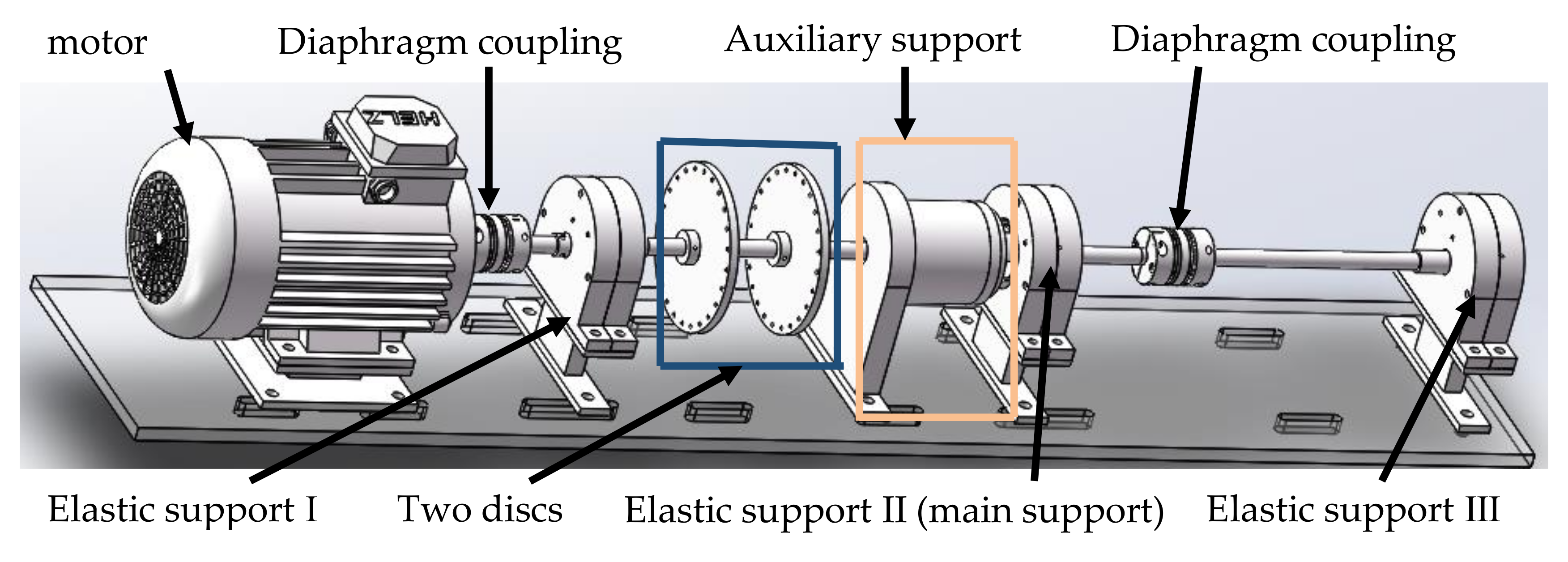
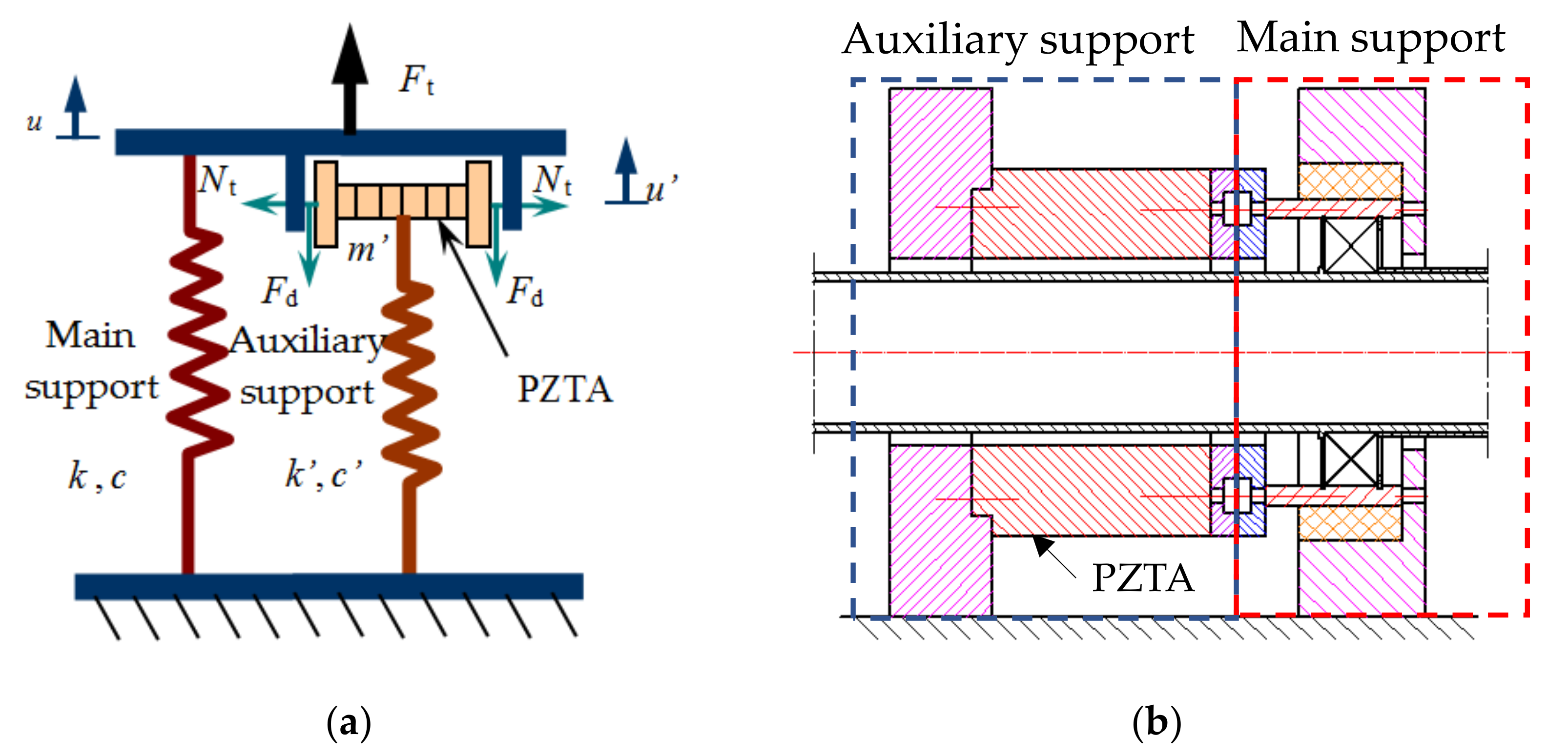
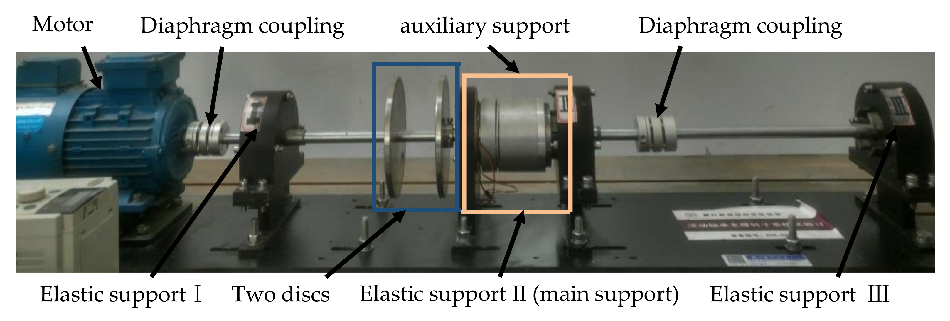
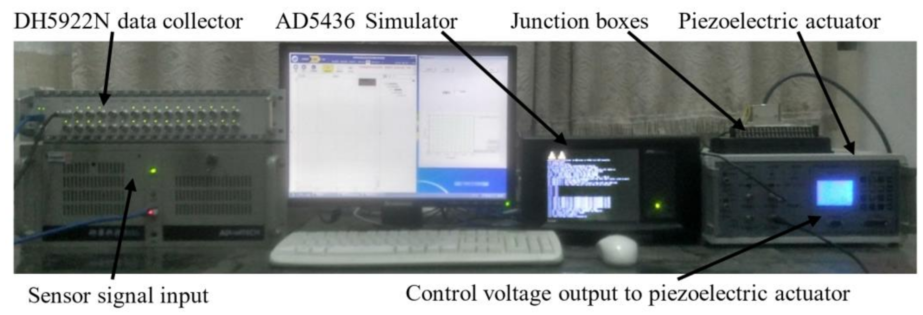
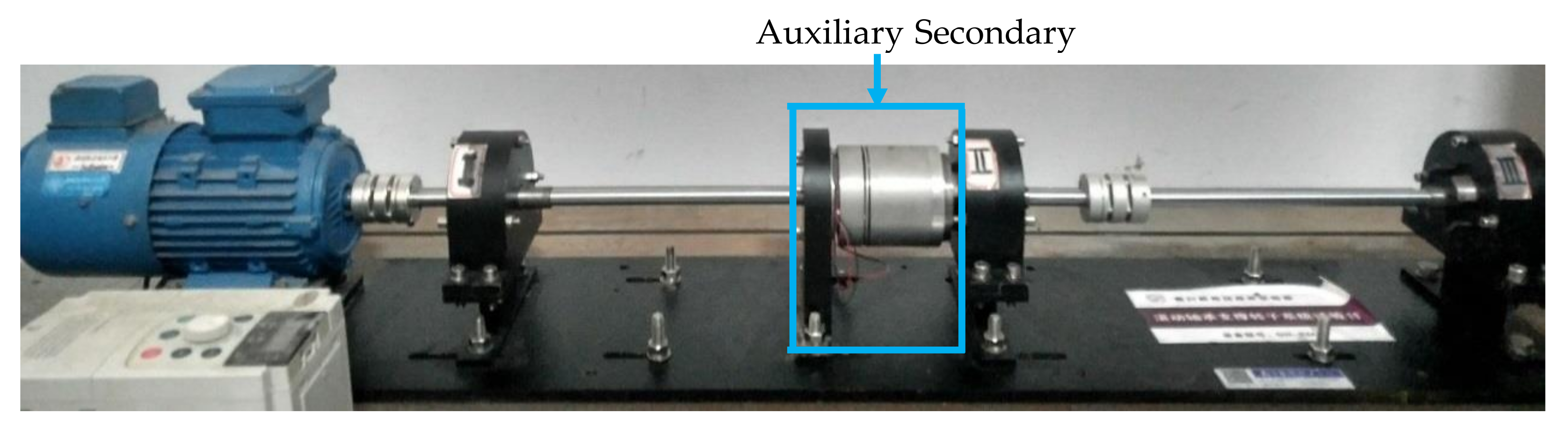
3.1. Design of Test System

The test system consisted of the shafting test bed, executive system, data acquisition system, and control system. The actuator system consisted of the piezoelectric ceramic controller and piezoelectric actuator. The data acquisition system included sensor, data collector DH5922N and its supporting software, DHDAS dynamic signal acquisition and analysis system. The control system included controller AD5436 and its supporting software. The layout of the test platform is shown in Figure 10 and Figure 11. In the experiment, the output voltage of the piezoelectric ceramic controller was increased by 15 V, and the corresponding shaft system over-critical response was recorded, and the test results were analyzed.
When the voltage was applied, the PZTA extended to both sides to make the main and auxiliary friction surfaces of the Smart Spring support tight. If the control voltage of the PZTA was increased after jacking, the support of the Smart Spring pair deformed in the axial direction. The axial displacement xa of the support under different loading voltages (0 V–150 V, step size 15 V) was measured by an eddy current sensor, which was the deformation xa of the Smart Spring support. Assuming that the axial stiffness ka of the auxiliary support remained constant with the increase of the force, then:
N t = k a × x a .
In Equation (1) ka is the axial stiffness of the auxiliary support and xa is the axial displacement of the auxiliary support.
As shown in Figure 12, the relationship between control force and control voltage was not a precise linear relationship, and there was a certain hysteresis effect. When the control voltage increased from 0 V to 150 V at 15 V intervals and then decreased to 0 V at 15 V intervals, the curves of the control force could not coincide, that is, the piezoelectric ceramics had a hysteresis effect. When the control voltage was 150 V, the maximum control force was 447 N.

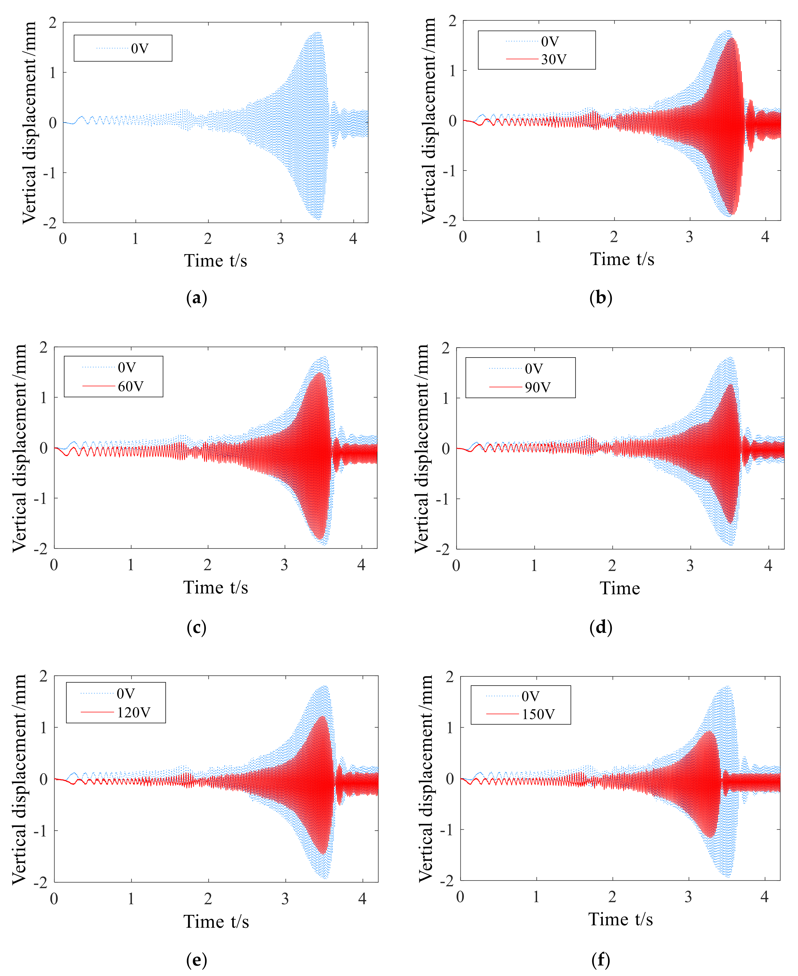
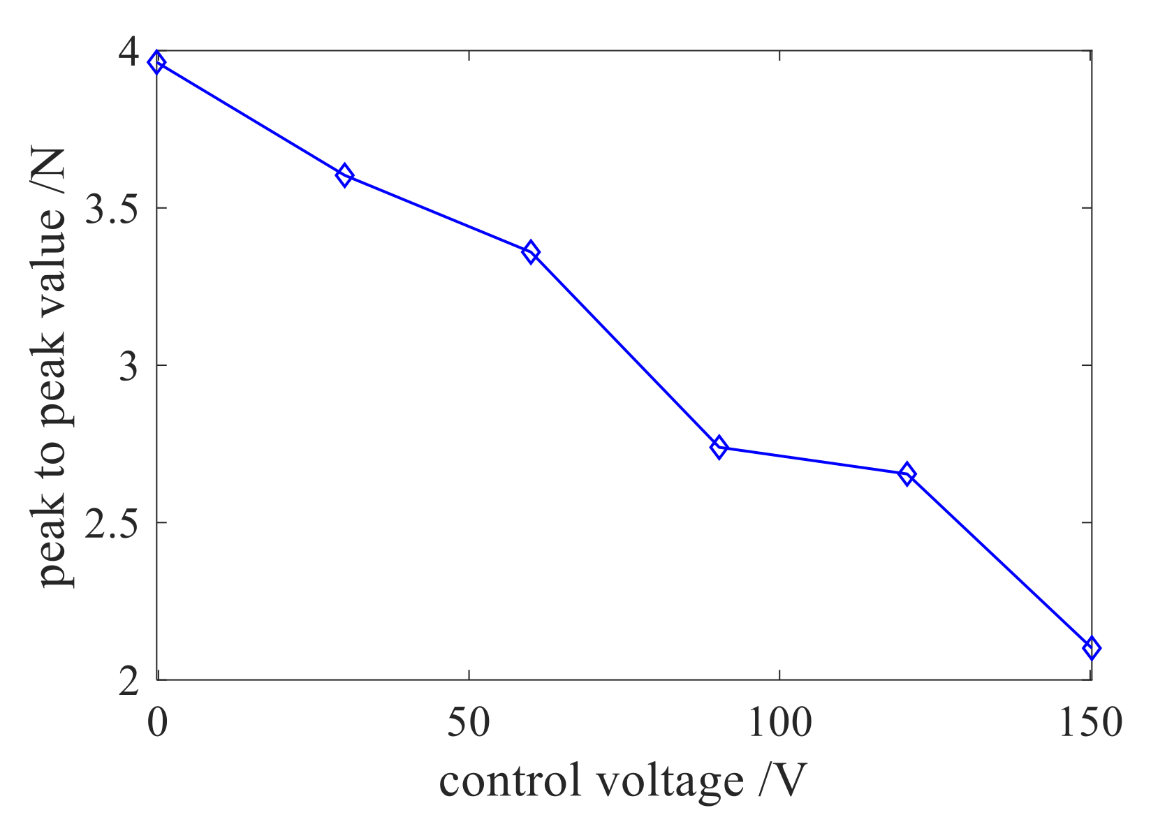
3.2. Analysis of Experiment Result

Figure 13 shows the critical time domain response of shafting under various control voltages. It can be seen from the figure that after the control voltage was applied, the peak value of the shaft acceleration over-critical value decreased obviously. With the increase of the control voltage, the vibration peak value decreased more obviously when the shafting was over-critical.
The relationship between the peak value of shaft acceleration and the control voltage under each control voltage is shown in Figure 14. It can be seen from the figure that the vibration reduction performance of the Smart Spring support was good, and the maximum vibration reduction rate reached 44.2% with the change trend of the vibration peak value with the control voltage.
Comparing Figure 14 and Figure 7, the change trend of the first section of the two figures was consistent, and the displacement response decreased with the increase of the control parameters. However, because of the small axial stiffness of the bearing pedestal and the limited displacement of the piezoelectric actuator, the optimal control parameter in Figure 14 appeared at the maximum value, and the maximum control force was 447 N, so the piezoelectric actuator failed to exert its maximum capacity.
Figure 15 shows the comparison results of the shafting vibration damping ratio under the different control voltages/control forces obtained by test and simulation analyses. It can be seen from the figure that under the trans-critical state of the shafting, the variation trends of the damping rate obtained by the test and simulation were the same, which indicated the accuracy of the joint simulation model. When the fixed control force of the intelligent spring increased from 100 N to 200 N, the vibration reduction rate of the simulation results increased by 21 percentage points, and the vibration reduction rate of the test results increased by 15 percentage points; when the control force of the intelligent spring increased from 200 N to 300 N, the vibration reduction rate of the simulation results and that of the test results increased by three percentage points. The difference between the experimental damping rate and the simulated damping rate was due to the error of the test bench and the limitation of the control force of the piezoelectric actuator. For example, there was a certain gap between the angular acceleration of the motor and the simulated angular acceleration, the axial stiffness of the bearing pedestal was too small, and the displacement of the piezoelectric ceramic actuator was limited.

4. Research on Vibration Reduction of Shafting with Function Control Force Exerted by Smart Spring

It can be seen from the previous analysis results that the vibration damping rate of the shafting was different at different speeds when the Smart Spring applied fixed control force. In order to obtain better control effect of shaft system over-critical vibration, a vibration suppression method with function control force was proposed. In other words, the function control force that changes with acceleration and time was applied to the Smart Spring. Therefore, after establishing the joint simulation model of shafting, the relationship between control force FN and time was studied to determine the optimal control force under constant operating speed, and then the control force function was determined to carry out joint simulation analysis on the critical open-loop control of the Smart Spring applying function control force.

4.1. Establishment of Simulation Model of Three-Support Shafting with Smart Spring

This section takes the three-support shafting test bed shown in Figure 16 as the research object, establishes the virtual prototype model and imports it into MATLAB to obtain the joint simulation model of three-support shafting with Smart Spring.

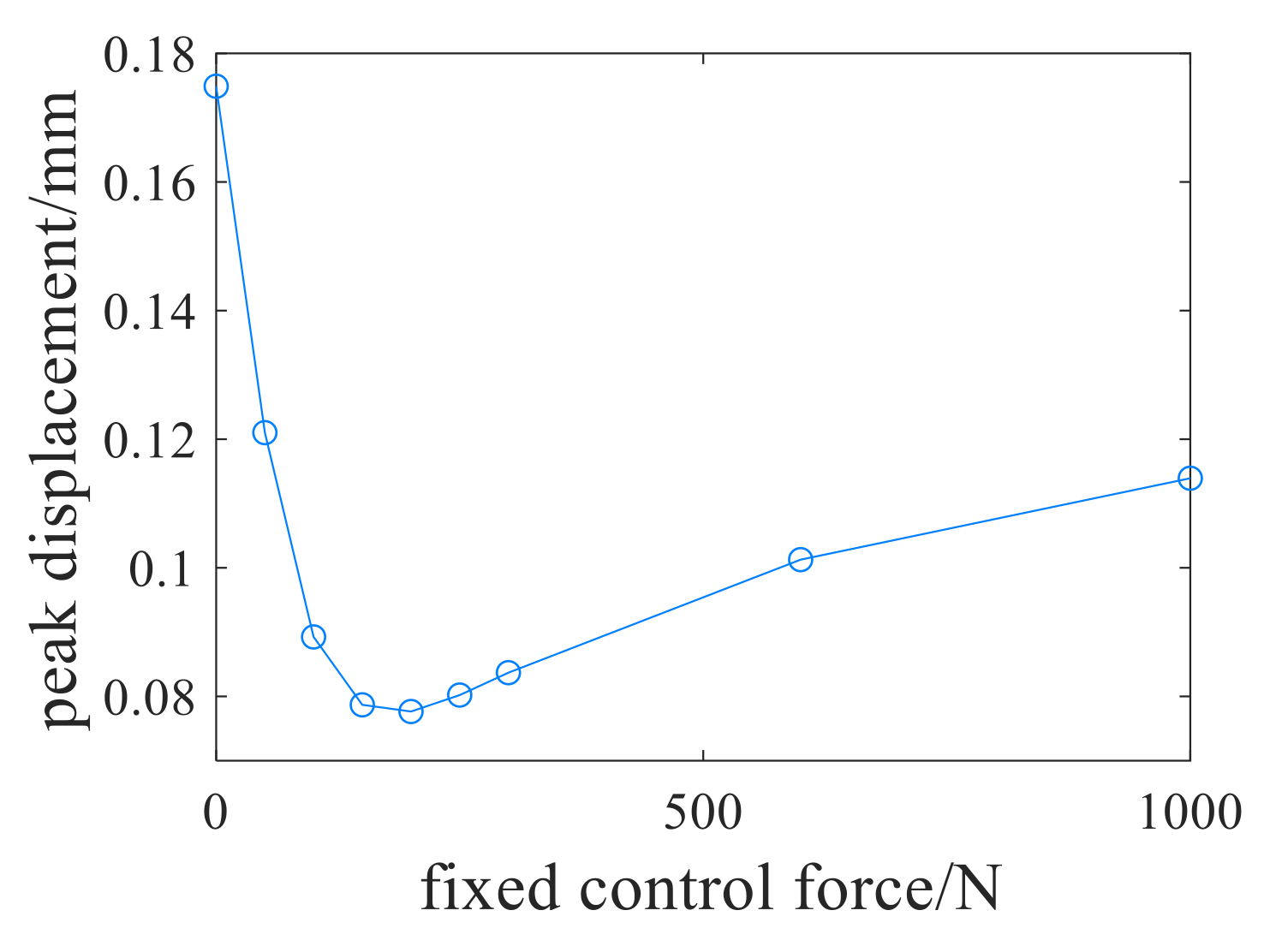
4.2. Determination of Optimal Fixed Control Force at Constant Speed

The joint simulation model under constant speed as shown in Figure 17 was established. In order to realize the constant speed operation of the shafting, a state variable was added to the input module to input the constant speed. In the speed range of 0–8400 r/min, the simulation of optimal fixed control force at constant speed was carried out with the interval of 600 r/min. The axis orbit of the shafting under different fixed control forces was obtained by simulation, and the control force with the minimum radius of the axis trajectory was selected as the optimal control force Fop.
Figure 18 shows the axis orbit of the steady-state response under each fixed control force when the shaft speed was 6000 r/min. It can be seen from the figure that the axis trajectories of the steady-state response were all circular. With the increase of the control force, the radius of the steady-state response also changed, which indicated that different fixed control forces had different suppression effects on the steady-state response of constant speed operation.
Since the optimal control forces in the speed range of 0–6000 r/min were all 1000 N, it was no longer necessary to analyze the case where the shaft speed was lower than 6000 r/min. Figure 19 shows the relationship between the fixed control force of the Smart Spring and the steady response of the steady-state response at the speeds of 6000 r/min, 6600 r/min, 7200 r/min, 7800 r/min, and 8400 r/min. It can be seen from the figure that with the increase of speed, the optimal control force Fop and the maximum damping rate of constant speed operation became smaller and smaller. When the speed was 6000 r/min, the optimal control force Fop was 1000 N, and the maximum vibration reduction rate was about 80%; when the speed was 6600 r/min, the optimal control force Fop was 650 N, and the maximum vibration reduction rate was about 58%; when the speed was 7200 r/min, the optimal control force Fop was 200 N, and the maximum damping rate was about 17%; when the speed was 8400 r/min, the optimal control force Fop was 25 N, and the maximum damping rate was close to zero.

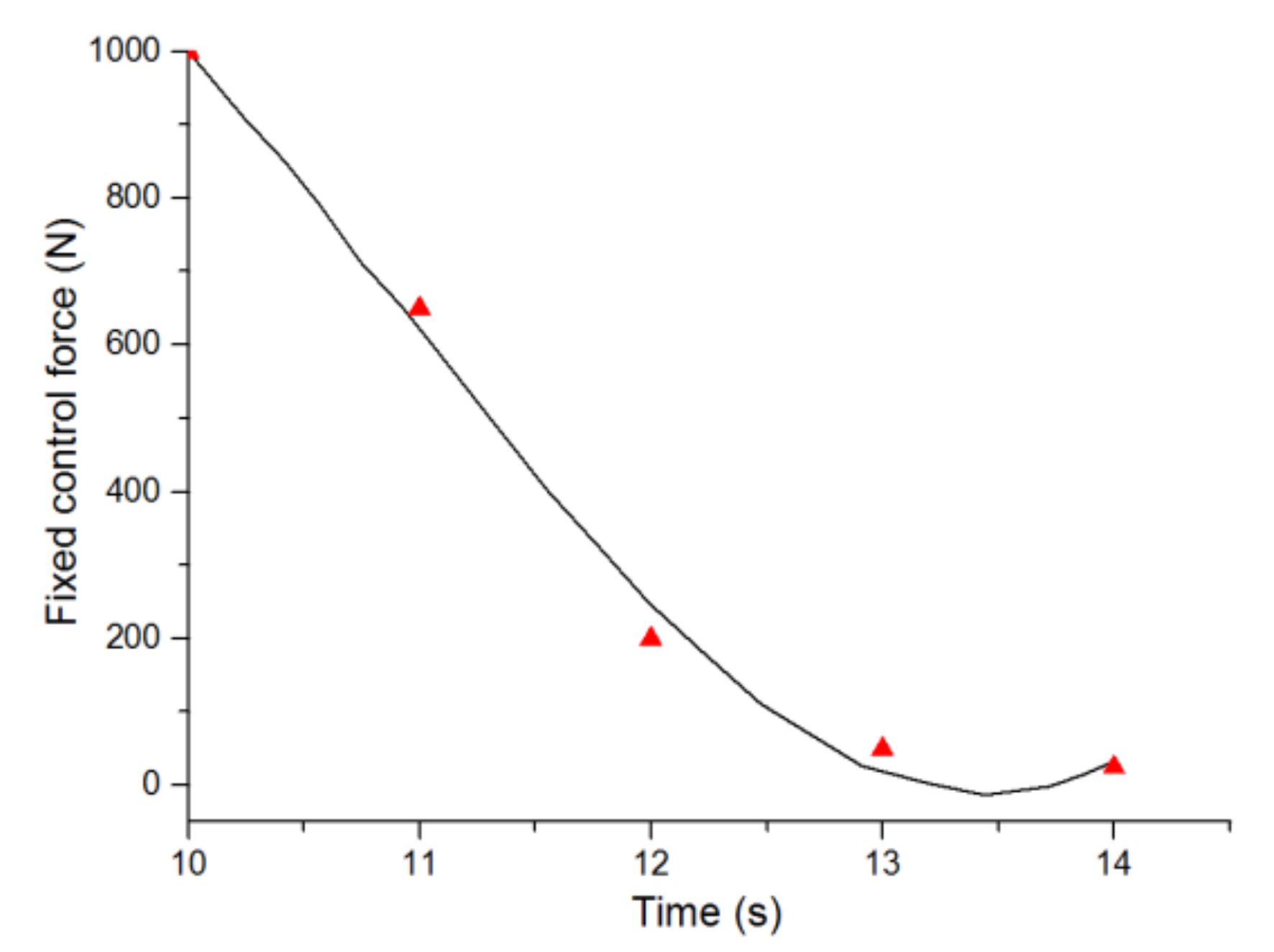
4.3. Polynomial Fitting of Function Control Force

According to the above analysis, the required control force is related to acceleration and time, so that
F N ( t ) = a 0 + a 1 t + a 2 t 2 + + a m t m .
When the shaft system was accelerated with an angular acceleration of 20π rad/s2, the times to reach 6000 r/min, 6600 r/min, 7200 r/min, 7800 r/min, and 8400 r/min were 10 s, 11 s, 12 s, 13 s, and 14 s, respectively, and the optimal control forces were 1000 N, 650 N, 200 N, 50 N and 25 N, respectively. Equation (2) is used to fit the functional relationship between control force FN and acceleration and time. The goal of fitting is to minimize the square sum D of the upper deviation, that is, Equation (3) is the minimum.
D = i = 1 N δ i 2 = i = 1 N F N ( t i ) F OP i 2 .
In Equation (3), the optimal control force is FOPi, the fixed control force is FN ( t i ) and the variance is δ.
According to the least square theorem, if N > m + 1, then there is a unique set of polynomial coefficients a0, a1am, which minimize the value of Equation (3), and
x m = A T A 1 A T b .
In Equation (4), x m = a 0   a 1   a 2   a m T , b = F OP 1   F OP 2 F OP N T , the value of matrix A is as follows:
A = 1 t 1 t 1 2 t 1 m 1 t 2 t 2 2 t 2 m 1 t N t N 2 t N m .
By substituting the time and fixed control force values corresponding to speeds of 6000 r/min, 6600 r/min, 7200 r/min, 7800 r/min, and 8400 r/min into Equation (4), the results show that a0 = 143,280, a1 = −57,510, a2 = 7687.2, a3 = −342.14, that is, the fitting function of optimal control force and time for 10 s ≤ t ≤ 14 s is as follows:
F N ( t ) = 143,280 57,510 t + 7687.2 t 2 342.14 t 3 .
According to Equation (5), the curve shown in Figure 20 is obtained.
According to the simulation results of the shaft center trajectory under constant speed, the optimal control force of the shafting was 1000 N in the speed range of 0–6000 r/min, i.e., within 0–10 s, the function control force expression of the optimal control force and time is as follows:
F N ( t ) = 1000 , 0 t 10 143,280 57,510 t 7687.2 t 2 342.14 t 3 , 10 < t 14 .

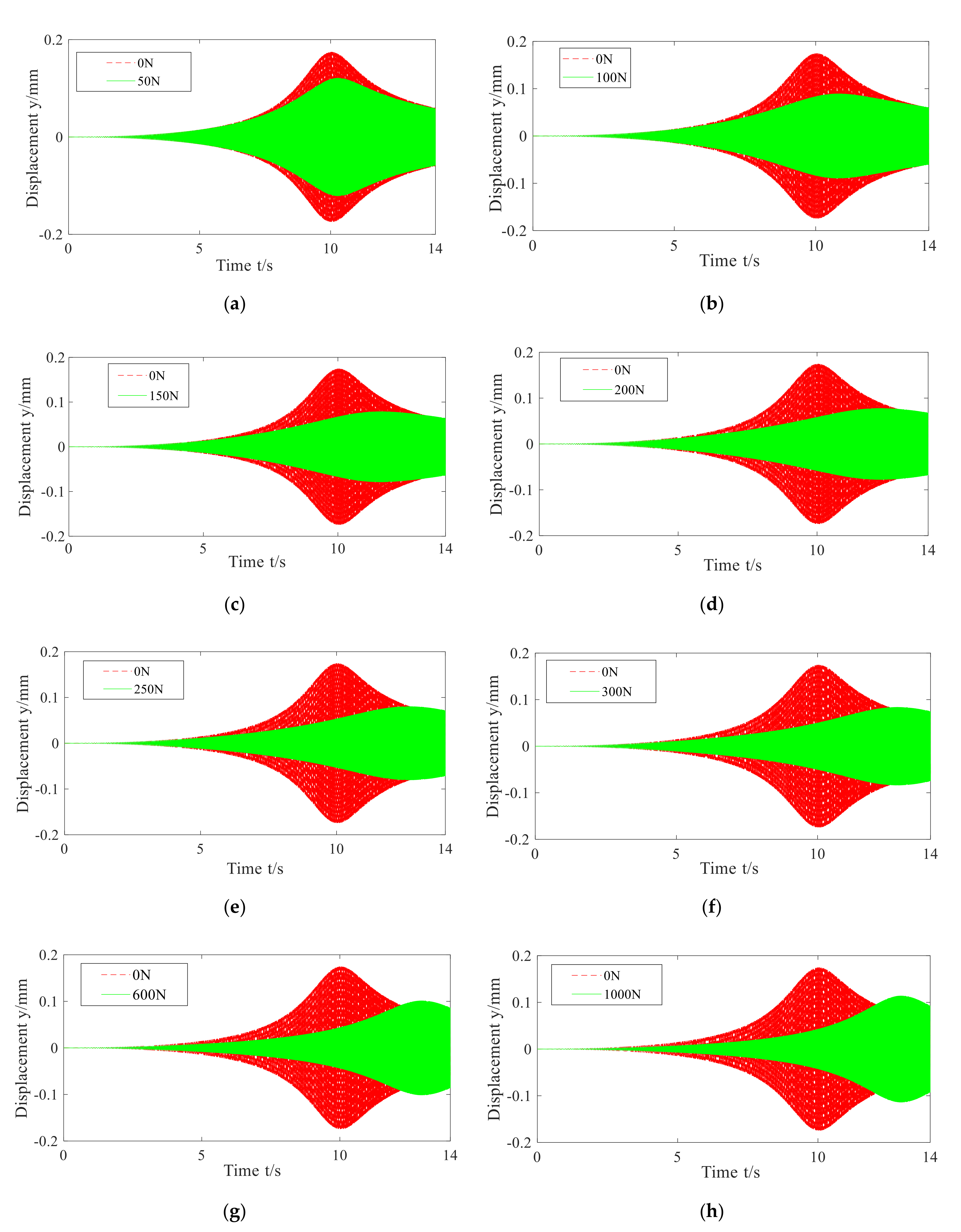
4.4. Analysis of Simulation Results of Supercritical

4.4.1. Analysis of Simulation Results of Over-Critical with Fixed Control Force

The midpoint of the central line between support I and support II was selected as the measuring point, and the displacement response at this point was measured. Figure 21 shows the critical bending vibration response of a three-support shafting with Smart Spring support under different fixed control forces. The fixed control forces applied were 50 N, 100 N, 150 N, 200 N, 250 N, 300 N, 600 N, and 1000 N, respectively. It can be seen from the figure that the application of fixed control force significantly inhibited the peak value of critical response, and the critical speed obviously shifted to the right; when the fixed control force was not greater than 100 N, the vibration response in the whole speed range of 0–8400 r/min (i.e., 0 s < t < 14 s) decreased; when the speed was lower than 7200 r/min (i.e., t < 12 s), the vibration was attenuated by applying 0–1000 N fixed control force, but when the rotating speed was less than 7200 r/min (when the speed was higher than 7800 r/min (i.e., t > 13 s)) and the fixed control force was greater than 150 N, the vibration increased when the fixed control force was applied.
Figure 22 shows the relationship between the peak displacement response of the measuring point and the fixed control force when the shafting was over-critical. It can be seen from the figure that with the increase in fixed control force, the peak value of critical response first decreased and then increased gradually. When the control force was 0 N, the peak value was 0.1749 mm; when the control force was 200 N, the peak value was the minimum, which was 0.0777 mm, and the maximum vibration reduction rate was 55.6%.
As shown in Figure 23, the first critical speed increased gradually and tended to be stable after the control force was greater than 600 N, which was close to 7800 r/min, that is, the damping control gradually transited to the stiffness control.
It can be concluded from Figure 22 and Figure 23 that the Smart Spring support has good vibration reduction performance. By applying fixed control force, the bending vibration response of three-support shafting accelerating through critical can be greatly attenuated, but the greater the control force, the better. The optimal fixed control force is 200 N, and the vibration response of shafting is the minimum.

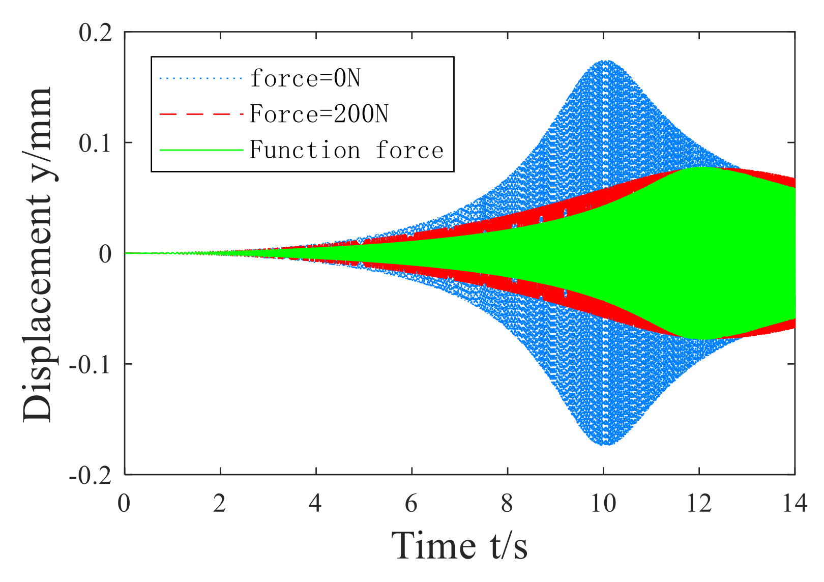
4.4.2. Analysis of Simulation Results of Applying Function Control Force Over-Critical

According to the determined function control force, the joint simulation model established in Figure 16 was modified, and then the function control force was applied to the model. A variable FN of function control force was established in the MATLAB workspace. FN contained two columns of data, the first column was time and the second column was the corresponding control force. The two output state variables are the displacement in X direction and Y direction at the midpoint of elastic supports I and II.
By comparing the vibration analysis results of the three-support shafting of the Smart Spring without control force, fixed control force, and function control force, Figure 24 and Figure 25 are obtained. It can be seen from the figure that the critical peak value of the function control force and the best fixed control force was 200 N, but in the whole speed range, the displacement response of the function control force was less than that of the fixed control force of 200 N, which achieved a better vibration reduction effect. Therefore, for the open-loop control of shaft system acceleration over-critical vibration, the vibration reduction effect of Smart Spring with function control force is the best.

5. Conclusions

Previous studies have proved that constant control force exerted by Smart Spring is effective for vibration control of shafting. However, there are few researches on the improvement of control strategy. Based on ADAMS and MATLAB simulation software, this paper analyzes the lateral bending vibration control of the shaft system under critical state, and improves the control strategy of the intelligent spring and proposes a vibration suppression method based on function control force. The main conclusions are as follows:
(1)
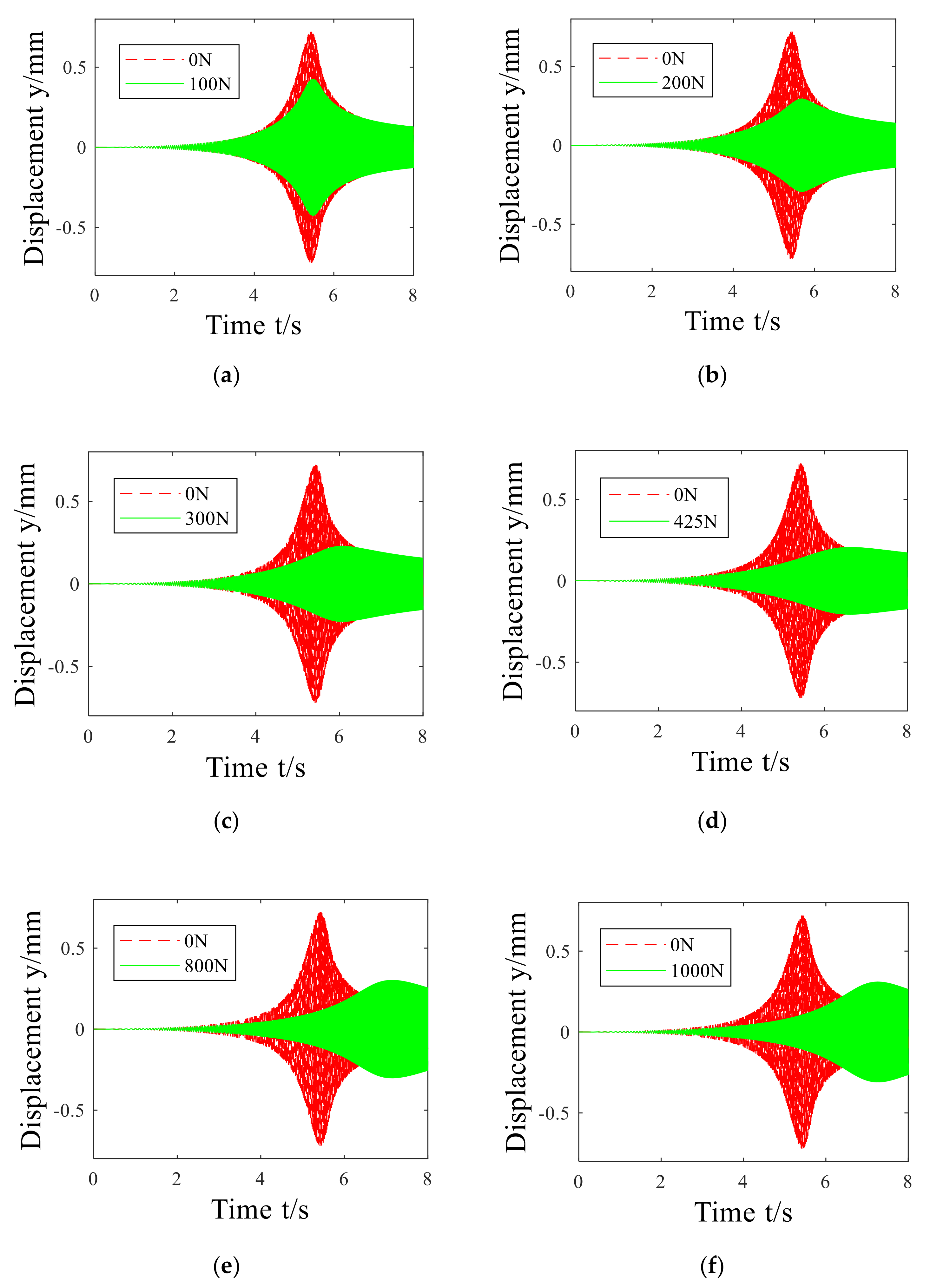
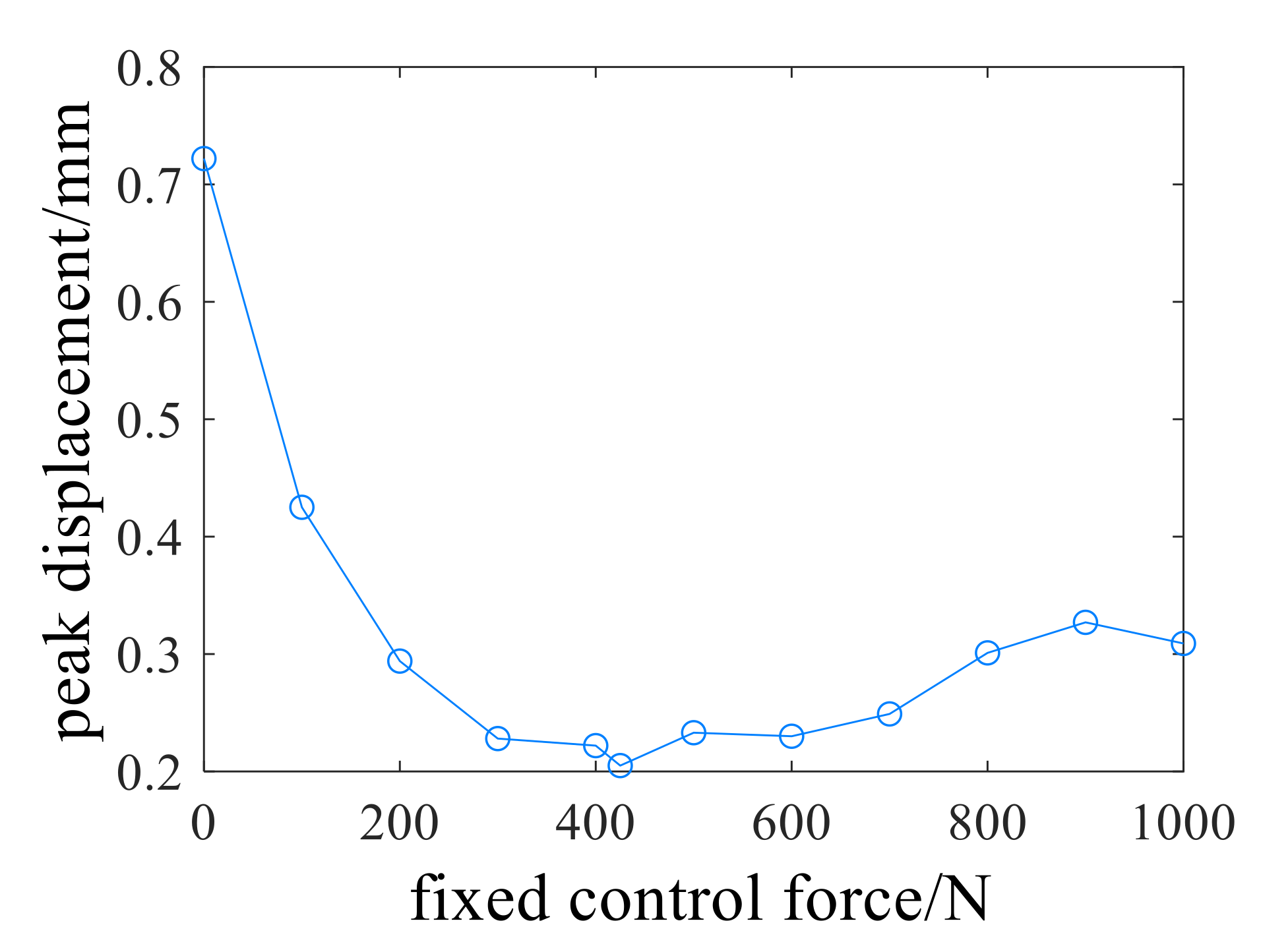
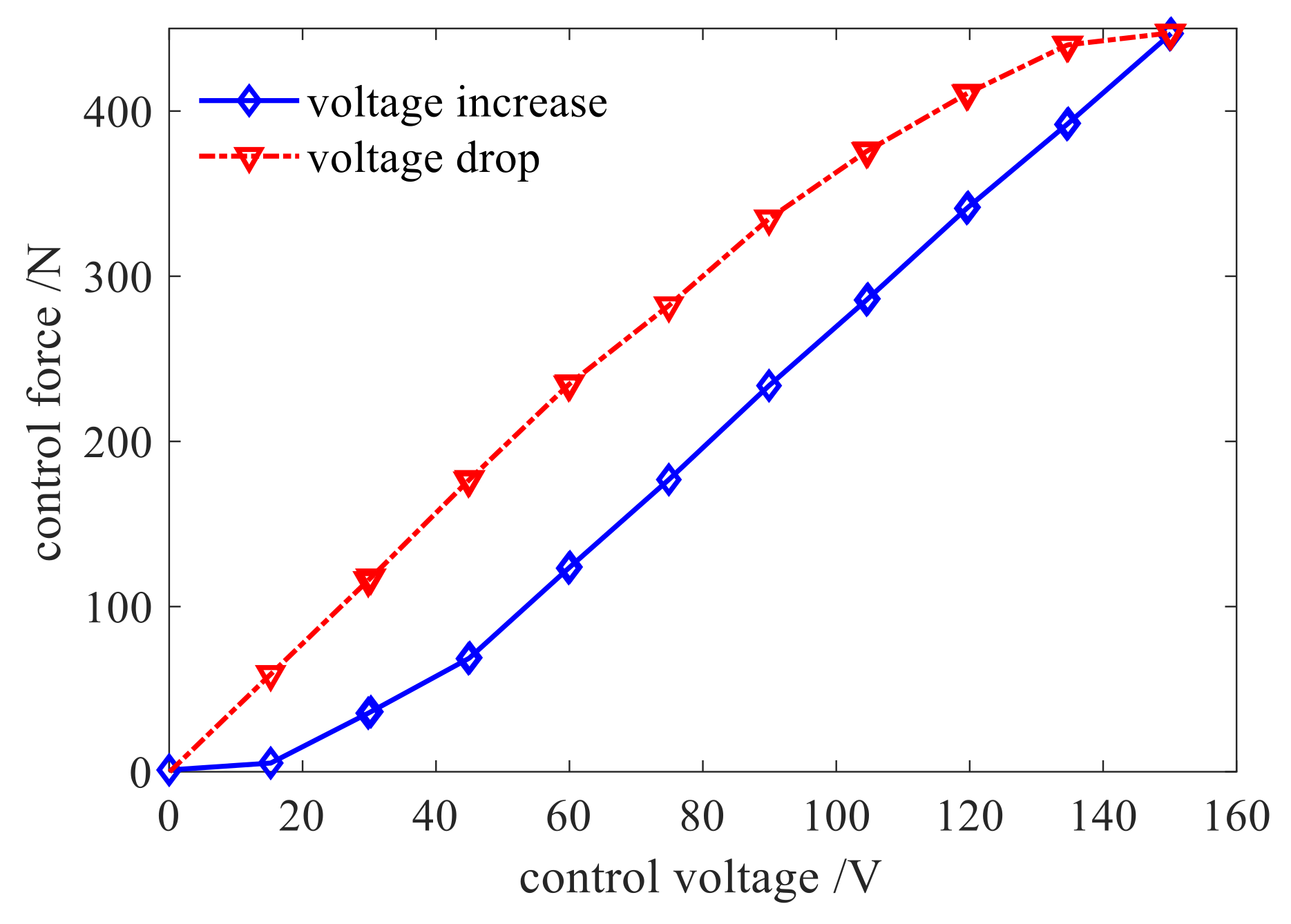
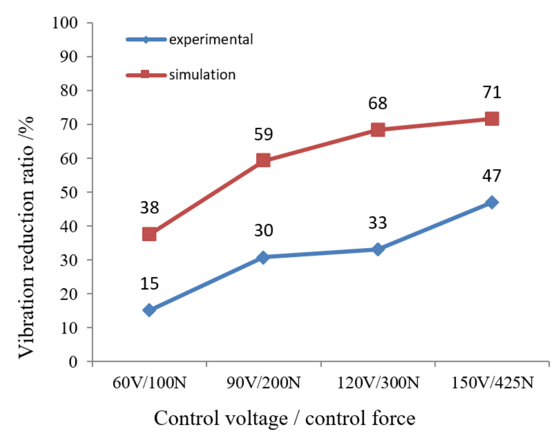
In this paper, the authors established a joint simulation model for the double-disk three-support shafting with Smart Spring, and carried out the open-loop control simulation and experimental study of the shafting over-critical vibration. The simulation results showed that the fixed control force exerted by the Smart Spring can greatly reduce the displacement response of the double-disk shaft system accelerating through the critical value. However, the fixed control force is not better when greater, but there is an optimal fixed control force making the vibration control effect the best. The optimal fixed control force is 425 N, and the vibration reduction rate is the maximum, which is 71.6%. The double-disk shafting test system was designed and tested. The test results showed that when the maximum control voltage is 150 V, the vibration reduction rate is the highest, reaching 44.2%, which verified that the Smart Spring support has good control effect on the lateral bending vibration of the three-support shafting when the acceleration is over-critical, and further proved the rationality of the joint simulation method.
(2)
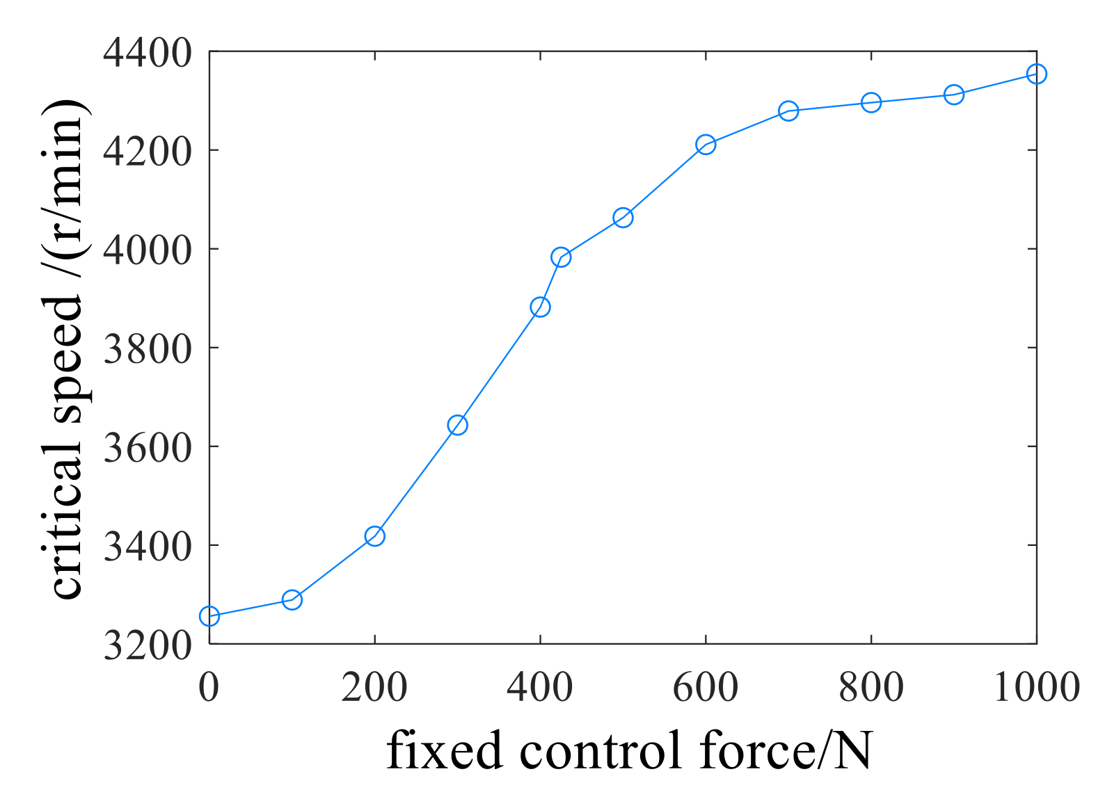
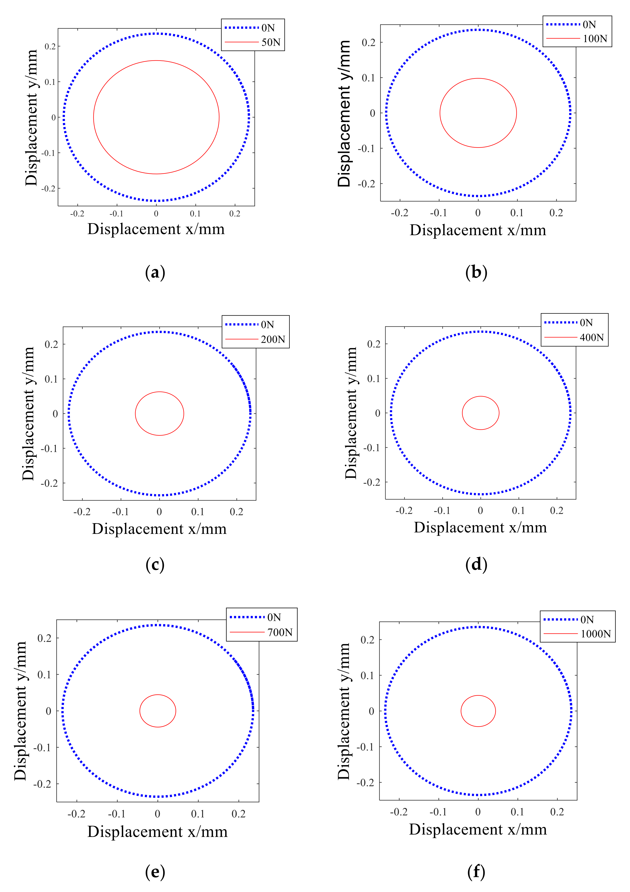
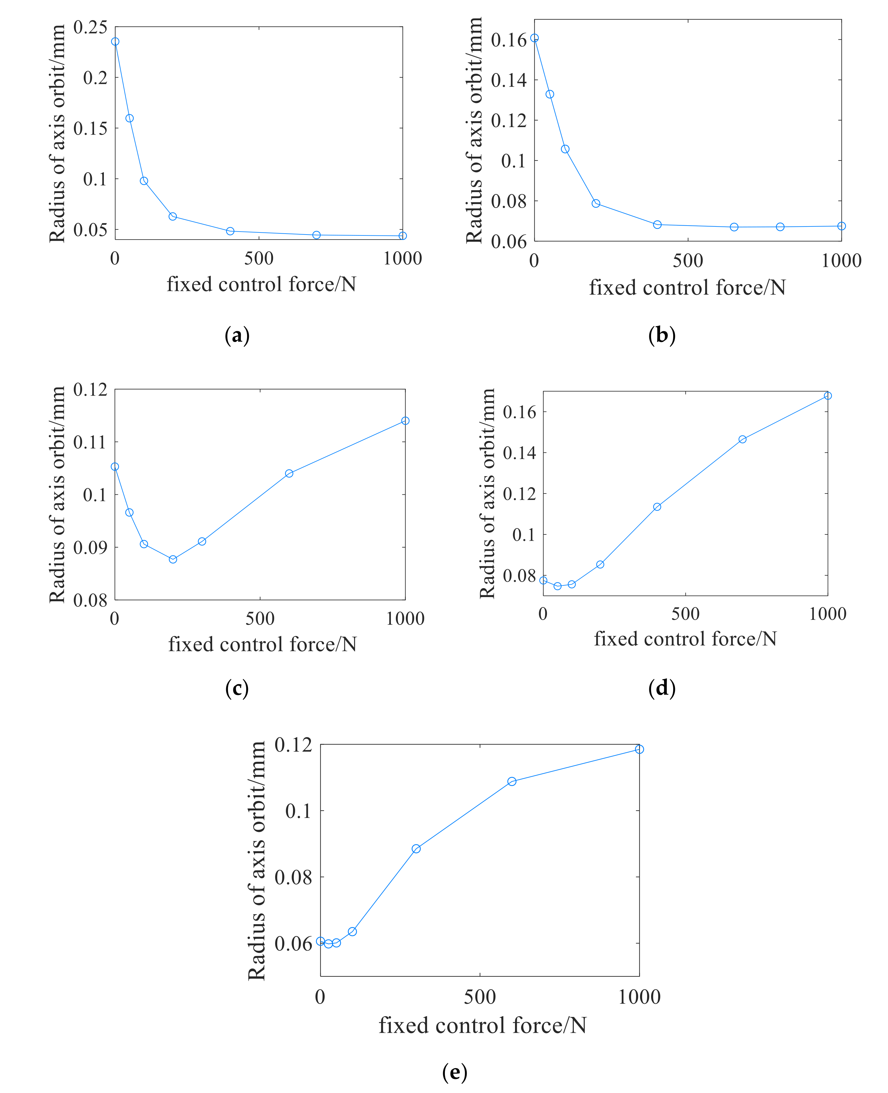
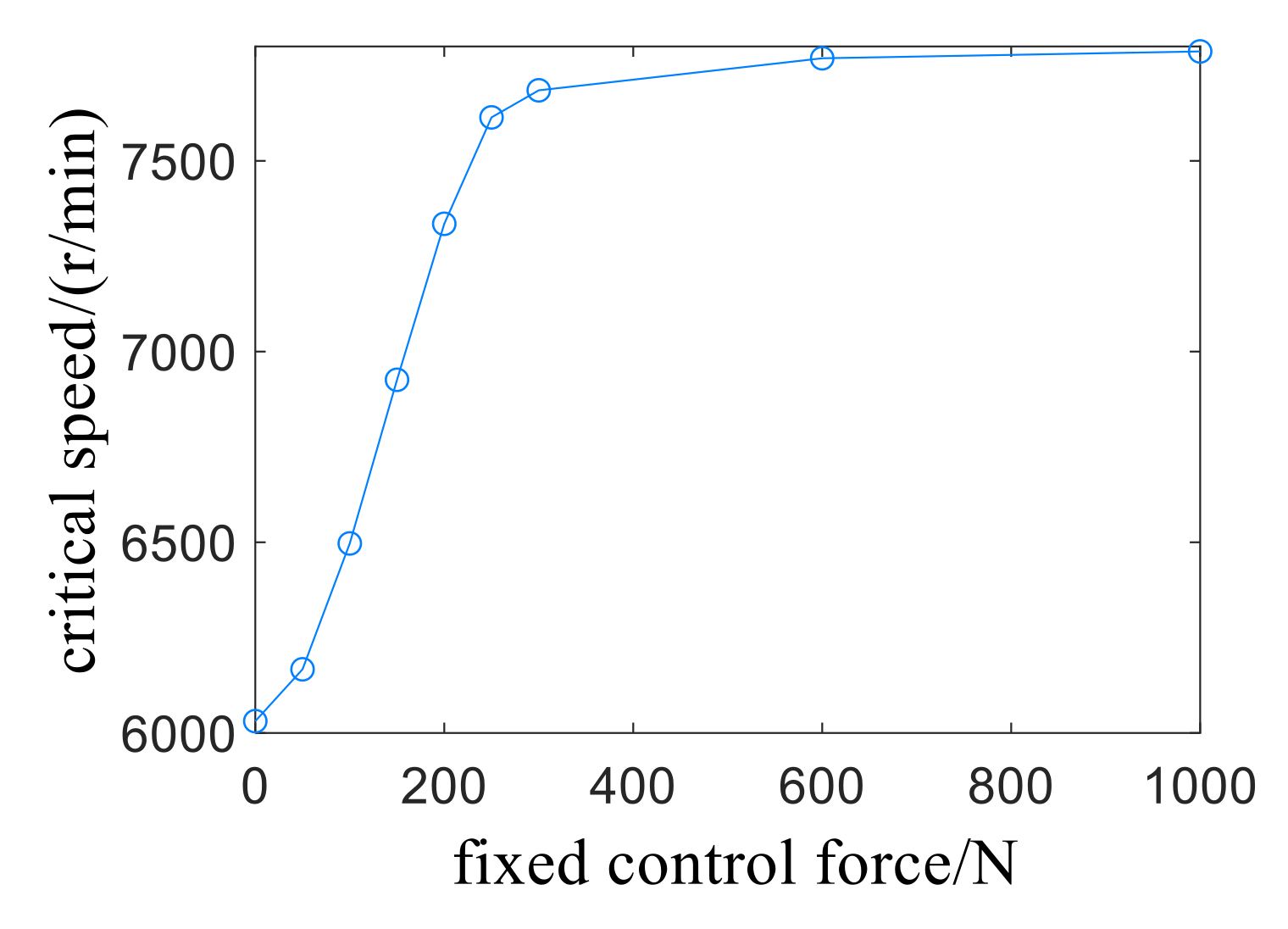
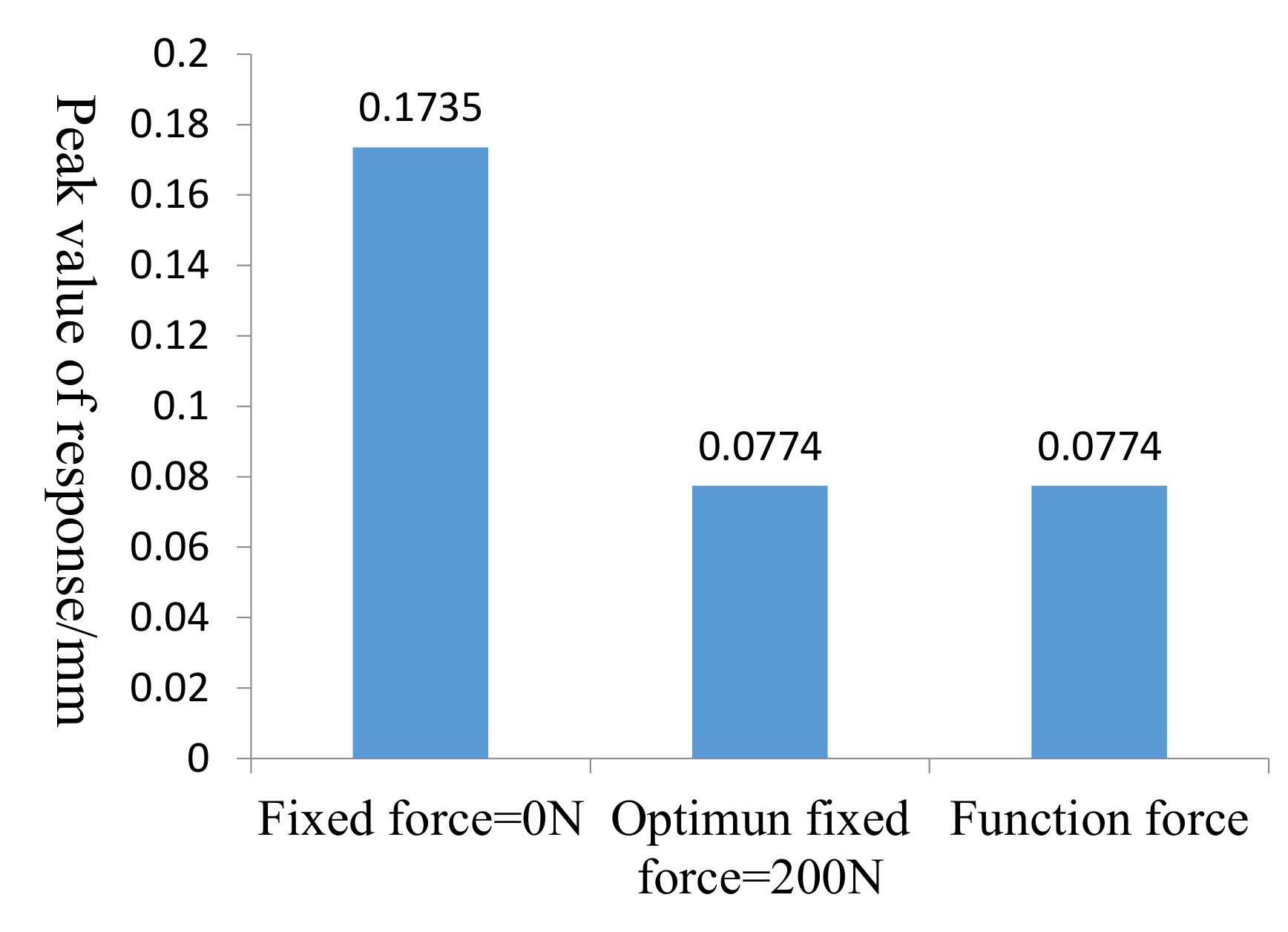
The open-loop control of the spring system was carried out by the joint control function of the spring system. The simulation results showed that with the increase of fixed control force, the first critical speed gradually increases and tends to be stable, and the peak value decreases first and then increases. The optimal fixed control force is 200 N, of which the maximum vibration reduction rate reaches 55.6%. Compared with the fixed control force, the displacement response of the function control force is significantly less than that of the fixed control force of 200 N, so it has a better vibration reduction effect.

Author Contributions

Conceptualization, M.-M.L. and L.-L.M.; methodology, M.-M.L.; software, M.-M.L.; validation, M.-M.L., L.-L.M. and C.-G.W.; data curation, L.-L.M.; writing—original draft preparation, L.-L.M.; writing—review and editing, M.-M.L.; supervision, C.-G.W.; project administration, R.-P.Z.; funding acquisition, R.-P.Z. All authors have read and agreed to the published version of the manuscript.

Funding

This work was supported by the National Natural Science Foundation of China (Grant No. 51775265), and the National Key Laboratory of Science and Technology on Helicopter Transmission (Nanjing University of Aeronautics and Astronautics) (Grant No. HTL-A-19G09).

Conflicts of Interest

The authors declare no conflict of interest.

References

  1. Meng, G. Retrospect and Prospect to the Research on Rotor Dynamics. Shock Noise 2002, 15, 1–9. [Google Scholar]
  2. Peng, B. Research on Multi-span Shaft Dynamics and Vibration Reduction via Smart Spring Support. Master’s Thesis, Nanjing University of Aeronautics and Astronautics, Nanjing, China, 2017. [Google Scholar]
  3. Li, W.Z.; Wang, L.Q. Review on Vibration Control Technology of High-speed Rotor System. J. Mech. Strength 2005, 27, 44–49. [Google Scholar]
  4. Zhang, T.; Meng, G.; Zhang, Z.X. Active Control of the Rotor System by Electromagnetic Bearing-Extrudod Oil Film Damper. J. Xi’an Pet. Inst. Nat. Sci. Ed. 2002, 6, 80–83. [Google Scholar]
  5. Xing, J. Research on Active Vibration Control of Rotor System Using Magnetorheological Fluid Damper. Master’s Thesis, Beijing University of Chemical Technology, Beijing, China, 2015. [Google Scholar]
  6. Qu, W.Z.; Sun, J.C.; Qiu, Y. Active control of vibration using a fuzzy control method. J. Sound Vib. 2004, 275, 917–930. [Google Scholar]
  7. Ishimatsu, T.; Shimomachi, T.; Taguchi, N. Active vibration control of flexible rotor using electromagneticdamper. In Proceedings of the IECON’91: 1991 International Conference on Industrial Electronics, Control and Instrumentation, Kobe, Japan, 28 October 1991; IEEE: Piscataway, NJ, USA. [Google Scholar]
  8. Palazzolo, A.B.; Jagannathan, S.; Kascak, A.F.; Montague, G.T.; Kiraly, L.J. Hybrid active vibration control of rotor bearing system using piezoelectric actuators. J. Vib. Acoust. 1993, 115, 111–119. [Google Scholar] [CrossRef]
  9. De, N. Research on Design Method of Smart Spring Damping System and Its Application in the Drive Shaft System. Ph.D. Thesis, Nanjing University of Aeronautics and Astronautics, Nanjing, China, 2015. [Google Scholar]
  10. Nitzsche, F. The use of smart structures in the realization of effective semi-active Control systems for vibration reduction. J. Braz. Soc. Mech. Sci. Eng. 2012, XXXIV, 371–377. [Google Scholar] [CrossRef] [Green Version]
  11. Nitzsche, F.; Feszty, D.; Grappasonni, C.; Coppotelli, G. Whirl-tower Open-loop Experiments and Simulations with an Adaptive Pitch Link Device for Helicopter Rotor Vibration. In Proceedings of the Aiaa/asme/asce/ahs/asc Structures, Structural Dynamics, & Materials Conference, Boston, MA, USA, 8–11 April 2013; pp. 1–13. [Google Scholar]
  12. Afagh, F.F.; Nitzsche, F.; Morozova, N. Dynamic modelling and stability of hingeless helicopter blades with a smart spring. Aeronaut. J. 2004, 108, 369–377. [Google Scholar] [CrossRef]
  13. Coppotelli, G.; Marzocca, P.; Ulker, F.D.; Campbell, J.; Nitzsche, F. Experimental Investigation on Modal Signature of Smart Spring/Helicopter Blade System. J. Aircr. 2008, 45, 1373–1380. [Google Scholar] [CrossRef]
  14. Chen, Y. Development of the smart spring for active vibration control of helicopter blades. J. Intell. Mater. Syst. Sructures 2004, 15, 37–47. [Google Scholar]
  15. Wickramasinghe, V. Experimental evaluation of the smart spring impedance control approach for adaptive vibration suppression. J. Intell. Mater. Syst. Sructures 2008, 19, 171–179. [Google Scholar] [CrossRef]
  16. Cavalini, A.A., Jr. Vibration attenuation in rotating machines using smart spring mechanism. In Mathematical Problems in Engineering; Hindawi Publishing Corporation: London, UK, 2011; pp. 1–14. [Google Scholar]
  17. NI, D.; Zhu, R.-P. Influencing factors of vibration suppression performance for a smart spring device. J. Vib. Shock 2012, 31, 87–98. [Google Scholar]
  18. Peng, B.; Zhu, R.; Li, M. Bending Vibration Suppression of a Flexible Multispan Shaft Using Smart Spring Support. Shock Vib. 2017, 2017, 1–12. [Google Scholar] [CrossRef]
Figure 1. Three-dimensional model of three-support shafting.
Applsci 10 06100 g001
Figure 2. (a) Principle sketch and (b) structure diagram of Smart Spring.
Applsci 10 06100 g002
Figure 3. Dynamic model of three-support shafting with double disks.
Applsci 10 06100 g003
Figure 4. Virtual prototype model of double-disk shafting.
Applsci 10 06100 g004
Figure 5. Realization of the Smart Spring function.
Applsci 10 06100 g005
Figure 6. Joint simulation model of open-loop control.
Applsci 10 06100 g006
Figure 7. Response of the shaft system under (af) fixed control forces, respectively 100 N, 200 N, 300 N, 425 N, 800 N and 1000 N of the Smart Spring.
Applsci 10 06100 g007
Figure 8. Relationship between peak value of over-critical response of shafting and fixed control force.
Applsci 10 06100 g008
Figure 9. Relationship between first critical speed and fixed control force of shafting.
Applsci 10 06100 g009
Figure 10. Shafting test bench.
Applsci 10 06100 g010
Figure 11. Layout of test data acquisition device.
Applsci 10 06100 g011
Figure 12. Relationship between control force and control voltage of the Smart Spring support.
Applsci 10 06100 g012
Figure 13. Accelerated over-critical vibration response of shafting under (af) control voltages, respectively 0 V, 30 V, 60 V, 90 V, 120 V and 150 V.
Applsci 10 06100 g013
Figure 14. Relationship between peak and peak value of shaft system over-critical vibration response and control voltage.
Applsci 10 06100 g014
Figure 15. Vibration reduction rate of shafting under different control voltages/forces.
Applsci 10 06100 g015
Figure 16. Three-support shafting test bench with Smart Spring pair support.
Applsci 10 06100 g016
Figure 17. Joint simulation model of applying function control force at constant speed.
Applsci 10 06100 g017
Figure 18. Steady-state response center orbit under (af) control forces at 6000 r/min, respectively 50 N, 100 N, 200 N, 400 N, 700 N and 1000 N.
Applsci 10 06100 g018
Figure 19. Relationship between the radius of the axis orbit and the fixed control force under (ae) speeds, respectively 6000 r/min, 6000 r/min, 6600 r/min, 7200 r/min, 7800 r/min and 8400 r/min.
Applsci 10 06100 g019
Figure 20. Control force fitting curve for 10 s ≤ t ≤ 14 s.
Applsci 10 06100 g020
Figure 21. Response of shaft system under (ah) fixed control forces, respectively 50 N, 100 N, 150 N, 200 N, 250 N, 300 N, 600 N and 1000 N.
Applsci 10 06100 g021
Figure 22. Relationship between peak displacement of measurement point and fixed control force.
Applsci 10 06100 g022
Figure 23. Relationship between first critical speed and fixed control force.
Applsci 10 06100 g023
Figure 24. Response curves of the shaft system under different control methods.
Applsci 10 06100 g024
Figure 25. Critical vibration peak value of shafting under different control methods.
Applsci 10 06100 g025
Table 1. Basic parameters of three-support shafting.
Parameter NameValue/UnitParameter NameValue/Unit
The density of the shaft ρ7850/(kg∙m−3)Elastic modulus E2 × 1011/Pa
Shaft radius r7.5/mmDisc radius R75/mm
Length of shaft l1120/mmDisc width b8/mm
Length of shaft l270/mmSupport stiffness kb1.7 × 105/(N∙m−1)
Length of shaft l380/mmSupport damping cb60/(N∙s∙m−1)
Length of shaft l4270/mmUnbalance magnitude e06.3 × 10−5 kg∙m
Length of shaft l3420/mmAuxiliary support stiffness ka6 × 105 N∙m−1

