The Optomechanical Response of a Cubic Anharmonic Oscillator

Abstract
:1. Introduction
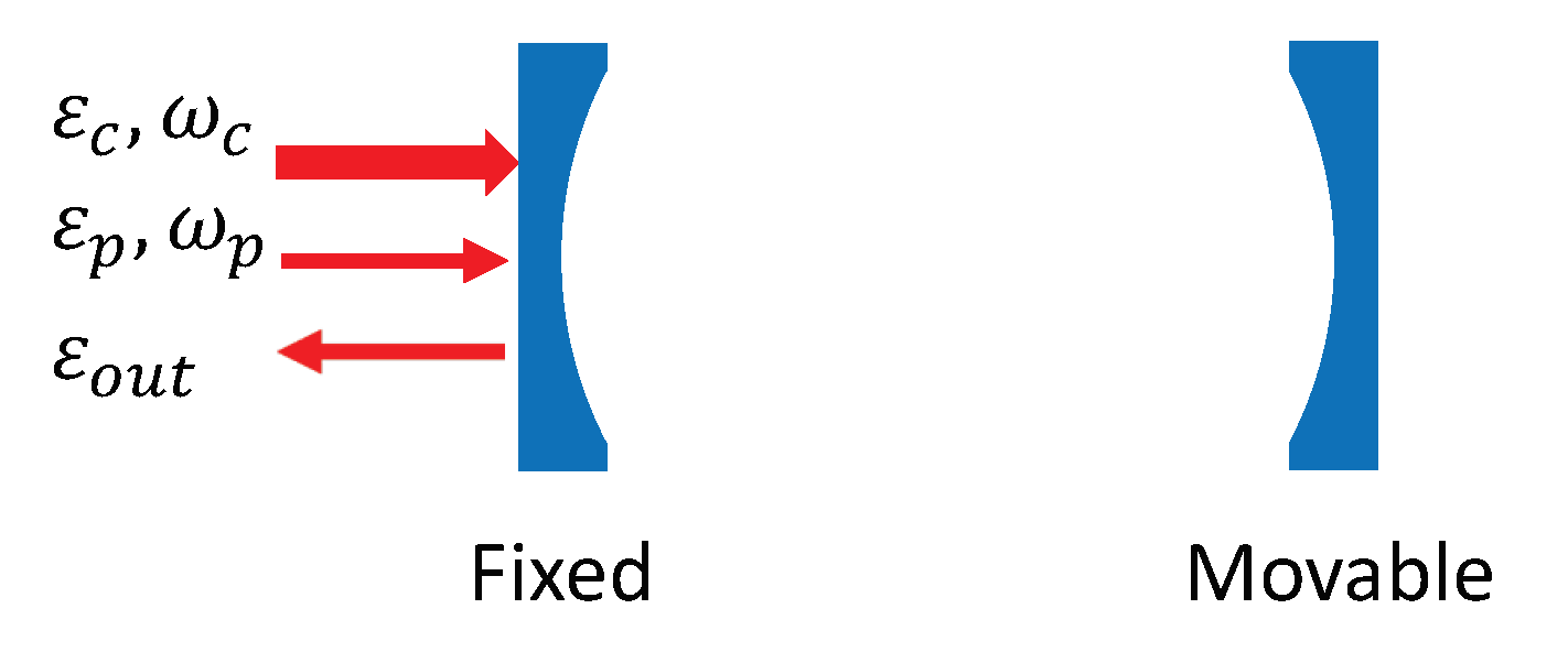
2. Model
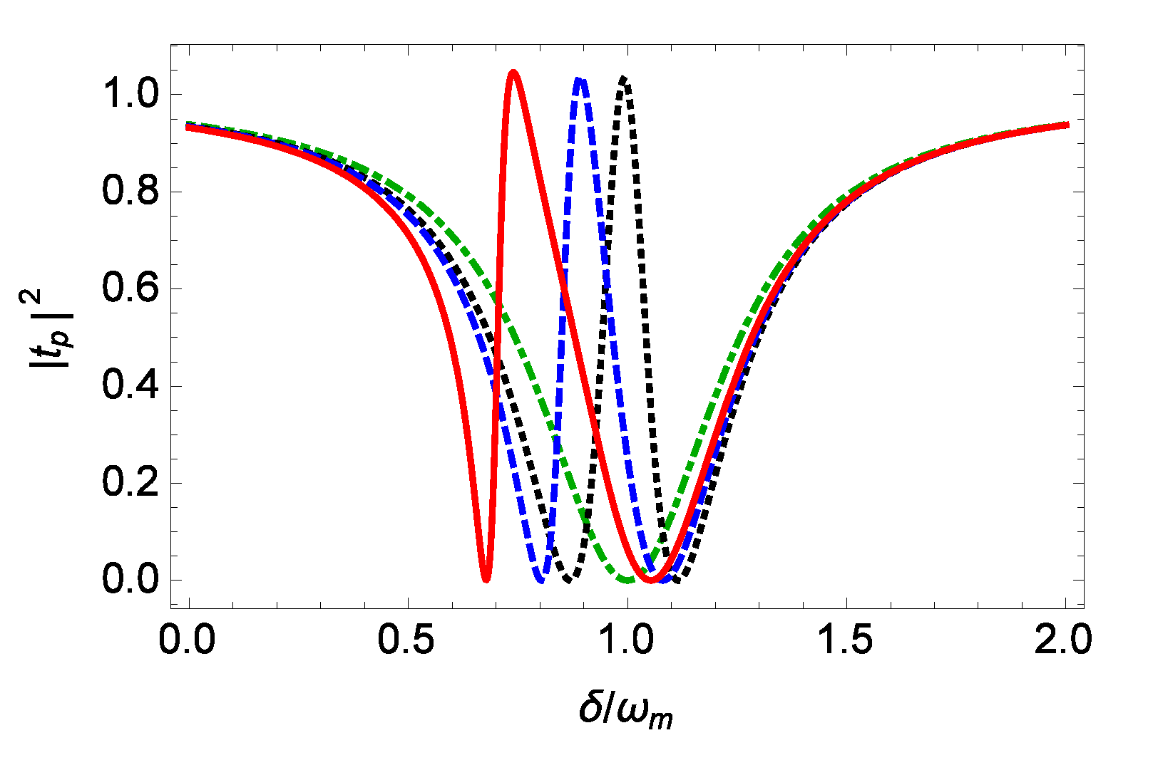
3. The Effect of the Mechanical Nonlinearity on the EIT
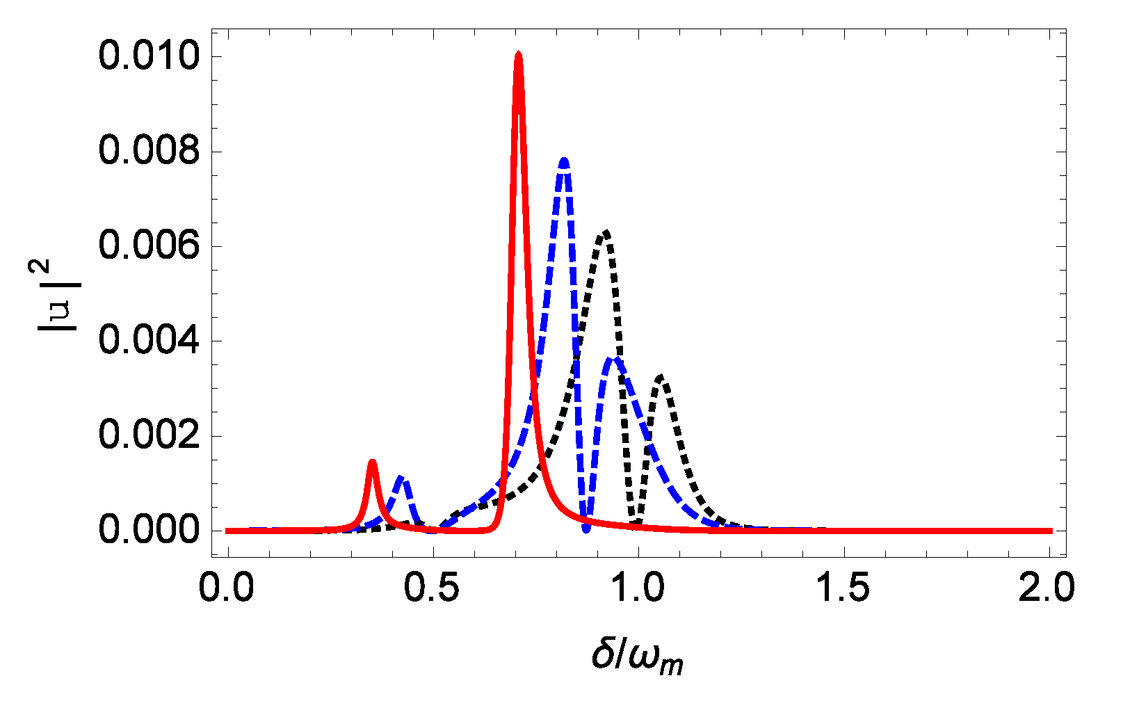
4. The Enhancement of the Second-Order Upper Sideband Generation by the Mechanical Nonlinearity
5. Conclusions
Author Contributions
Funding
Conflicts of Interest
References
- Aspelmeyer, M.; Kippenberg, T.J.; Marquardt, F. Cavity optomechanics. Rev. Mod. Phys. 2014, 86, 1391. [Google Scholar] [CrossRef]
- Gavartin, E.; Verlot, P.; Kippenberg, T.J. A hybrid on-chip opto-nanomechanical transducer for ultra-sensitive force measurements. Nat. Nanotechnol. 2012, 7, 509–514. [Google Scholar] [PubMed] [Green Version]
- Stannigel, K.; Rabl, P.; Sørensen, A.S.; Zoller, P.; Lukin, M.D. Optomechanical transducers for long-distance quantum communication. Phys. Rev. Lett. 2010, 105, 220501. [Google Scholar] [CrossRef] [PubMed] [Green Version]
- Teufel, J.D.; Donner, T.; Li, D.; Harlow, J.W.; Allman, M.S.; Cicak, K.; Sirois, A.J.; Whittaker, J.D.; Lehnert, K.W.; Simmonds, R.W. Sideband cooling of micromechanical motion to the quantum ground state. Nature (London) 2011, 475, 359–363. [Google Scholar] [CrossRef] [Green Version]
- Chan, J.; Alegre, T.P.M.; Safavi-Naeini, A.H.; Hill, J.T.; Krause, A.; Gröblacher, S.; Aspelmeyer, M.; Painter, O. Laser cooling of a nanomechanical oscillator into its quantum ground state. Nature (London) 2011, 478, 89–92. [Google Scholar] [CrossRef] [Green Version]
- Jähne, K.; Genes, C.; Hammerer, K.; Wallquist, M.; Polzik, E.S.; Zoller, P. Cavity-assisted squeezing of a mechanical oscillator. Phys. Rev. A 2009, 79, 063819. [Google Scholar] [CrossRef]
- Agarwal, G.S.; Huang, S. Strong mechanical squeezing and its detection. Phys. Rev. A 2016, 93, 043844. [Google Scholar] [CrossRef] [Green Version]
- Wollman, E.E.; Lei, C.U.; Weinstein, A.J.; Suh, J.; Kronwald, A.; Marquardt, F.; Clerk, A.A.; Schwab, K.C. Quantum squeezing of motion in a mechanical resonator. Science 2015, 349, 952–955. [Google Scholar] [CrossRef] [Green Version]
- Paternostro, M.; Vitali, D.; Gigan, S.; Kim, M.S.; Brukner, C.; Eisert, J.; Aspelmeyer, M. Creating and probing multipartite macroscopic entanglement with light. Phys. Rev. Lett. 2007, 99, 250401. [Google Scholar] [CrossRef]
- Palomaki, T.A.; Teufel, J.D.; Simmonds, R.W.; Lehnert, K.W. Entangling mechanical motion with microwave fields. Science 2013, 342, 710–713. [Google Scholar] [CrossRef]
- Riedinger, R.; Hong, S.; Norte, R.A.; Slater, J.A.; Shang, J.; Krause, A.G.; Anant, V.; Aspelmeyer, M.; Gröblacher, S. Nonclassical correlations between single photons and phonons from a mechanical oscillator. Nature (London) 2016, 530, 313–316. [Google Scholar] [CrossRef] [PubMed]
- Gröblacher, S.; Hammerer, K.; Vanner, M.R.; Aspelmeyer, M. Observation of strong coupling between a micromechanical resonator and an optical cavity field. Nature (London) 2009, 460, 724–727. [Google Scholar] [CrossRef] [PubMed] [Green Version]
- Dobrindt, J.M.; Wilson-Rae, I.; Kippenberg, T.J. Parametric normal-mode splitting in cavity optomechanics. Phys. Rev. Lett. 2008, 101, 263602. [Google Scholar] [CrossRef] [PubMed] [Green Version]
- Agarwal, G.S.; Huang, S. Electromagnetically induced transparency in mechanical effects of light. Phys. Rev. A 2010, 81, 041803(R). [Google Scholar] [CrossRef] [Green Version]
- Weis, S.; Rivière, R.; Deléglise, S.; Gavartin, E.; Arcizet, O.; Schliesser, A.; Kippenberg, T.J. Optomechanically induced transparency. Science 2010, 300, 1520–1523. [Google Scholar] [CrossRef] [Green Version]
- Safavi-Naeini, A.H.; Mayer Alegre, T.P.; Chan, J.; Eichenfield, M.; Winger, M.; Lin, Q.; Hill, J.T.; Chang, D.E.; Painter, O. Electromagnetically induced transparency and slow light with optomechanics. Nature 2011, 472, 69–73. [Google Scholar] [CrossRef] [Green Version]
- Dong, C.; Fiore, V.; Kuzyk, M.C.; Wang, H. Transient optomechanically induced transparency in a silica microsphere. Phys. Rev. A 2013, 87, 055802. [Google Scholar] [CrossRef]
- Zhou, X.; Hocke, F.; Schliesser, A.; Marx, A.; Huebl, H.; Gross, R.; Kippenberg, T.J. Slowing, advancing and switching of microwave signals using circuit nanoelectromechanics. Nat. Phys. 2013, 9, 179–184. [Google Scholar] [CrossRef] [Green Version]
- Fiore, V.; Yang, Y.; Kuzyk, M.C.; Barbour, R.; Tian, L.; Wang, H. Storing optical information as a mechanical excitation in a silica optomechanical resonator. Phys. Rev. Lett. 2011, 107, 133601. [Google Scholar] [CrossRef] [Green Version]
- Agarwal, G.S.; Huang, S. Optomechanical systems as single-photon routers. Phys. Rev. A 2012, 85, 021801(R). [Google Scholar] [CrossRef] [Green Version]
- Liu, Y.C.; Li, B.B.; Xiao, Y.F. Electromagnetically induced transparency in optical microcavities. Nanophotonics 2017, 6, 789–811. [Google Scholar] [CrossRef]
- Xiong, H.; Wu, Y. Fundamentals and applications of optomechanically induced transparency. Appl. Phys. Rev. 2018, 5, 031305. [Google Scholar] [CrossRef]
- Kaajakari, V.; Mattila, T.; Oja, A.; Seppä, H. Nonlinear limits for single-crystal silicon microresonators. J. Microelectromech. Syst. 2004, 13, 715–724. [Google Scholar] [CrossRef] [Green Version]
- Huang, P.; Zhou, J.W.; Zhang, L.; Hou, D.; Lin, S.C.; Deng, W.; Meng, C.; Duan, C.K.; Ju, C.Y.; Zheng, X.; et al. Generating giant and tunable nonlinearity in a macroscopic mechanical resonator from a single chemical bond. Nat. Commun. 2016, 7, 11517. [Google Scholar] [CrossRef] [PubMed]
- Jacobs, K.; Landahl, A.J. Engineering giant nonlinearities in quantum nanosystems. Phys. Rev. Lett. 2009, 103, 067201. [Google Scholar] [CrossRef] [Green Version]
- Rips, S.; Kiffner, M.; Wilson-Rae, I.; Hartmann, M.J. Steady-state negative Wigner functions of nonlinear nanomechanical oscillators. New J. Phys. 2012, 14, 023042. [Google Scholar] [CrossRef]
- Lü, X.Y.; Liao, J.Q.; Tian, L.; Nori, F. Steady-state mechanical squeezing in an optomechanical system via Duffing nonlinearity. Phys. Rev. A 2015, 91, 013834. [Google Scholar] [CrossRef] [Green Version]
- Xiong, H.; Si, L.G.; Zheng, A.S.; Yang, X.; Wu, Y. Higher-order sidebands in optomechanically induced transparency. Phys. Rev. A 2012, 86, 013815. [Google Scholar] [CrossRef] [Green Version]
- Kong, C.; Xiong, H.; Wu, Y. Coulomb-interaction-dependent effect of high-order sideband generation in an optomechanical system. Phys. Rev. A 2017, 95, 033820. [Google Scholar] [CrossRef] [Green Version]
- Liu, S.; Liu, B.; Wang, J.; Sun, T.; Yang, W. Realization of a highly sensitive mass sensor in a quadratically coupled optomechanical system. Phys. Rev. A 2019, 99, 033822. [Google Scholar] [CrossRef]
- Li, J.; Li, J.; Xiao, Q.; Wu, Y. Giant enhancement of optical high-order sideband generation and their control in a dimer of two cavities with gain and loss. Phys. Rev. A 2016, 93, 063814. [Google Scholar] [CrossRef]
- Liu, Z.X.; Xiong, H.; Wu, Y. Generation and amplification of a high-order sideband induced by two-level atoms in a hybrid optomechanical system. Phys. Rev. A 2018, 97, 013801. [Google Scholar] [CrossRef] [Green Version]
- Paris, M.G.A.; Genoni, M.G.; Shammah, N.; Teklu, B. Quantifying the nonlinearity of a quantum oscillator. Phys. Rev. A 2014, 90, 012104. [Google Scholar] [CrossRef] [Green Version]
- Latmiral, L.; Armata, F.; Genoni, M.G.; Pikovski, I.; Kim, M.S. Probing anharmonicity of a quantum oscillator in an optomechanical cavity. Phys. Rev. A 2016, 93, 052306. [Google Scholar] [CrossRef] [Green Version]
- Davydov, A. Quantum Mechanics; Pergamon: New York, NY, USA, 1965. [Google Scholar]
- Alvarez, G. Coupling-constant behavior of the resonances of the cubic anharmonic oscillator. Phys. Rev. A 1988, 37, 4079. [Google Scholar] [CrossRef] [PubMed]
- Cveticanin, L.; Zukovic, M.; Mester, G.; Biro, I.; Sarosi, J. Oscillators with symmetric and asymmetric quadratic nonlinearity. Acta Mech. 2016, 227, 1727–1742. [Google Scholar] [CrossRef]
- Bender, C.M.; Boettcher, S. Real spectra in non-Hermitian Hamiltonians having PT symmetry. Phys. Rev. Lett. 1998, 80, 5243. [Google Scholar] [CrossRef] [Green Version]
- Bender, C.M.; Dunne, G.V. Large-order perturbation theory for a non-Hermitian PT-symmetric Hamiltonian. J. Math. Phys. 1999, 40, 4616–4621. [Google Scholar] [CrossRef] [Green Version]
- Bender, C.M.; Weniger, E.J. Numerical evidence that the perturbation expansion for a non-Hermitian PT-symmetric Hamiltonian is Stieltjes. J. Math. Phys. 2001, 42, 2167–2183. [Google Scholar] [CrossRef] [Green Version]
- Ferreira, E.M.; Sesma, J. Global solution of the cubic oscillator. J. Phys. A Math. Theor. 2014, 47, 415306. [Google Scholar] [CrossRef] [Green Version]
- Mera, H.; Pedersen, T.G.; Nikolić, B.K. Nonperturbative quantum physics from low-order perturbation theory. Phys. Rev. Lett. 2015, 115, 143001. [Google Scholar] [CrossRef] [PubMed] [Green Version]
- Kronwald, A.; Marquardt, F. Optomechanically induced transparency in the nonlinear quantum regime. Phys. Rev. Lett. 2013, 111, 133601. [Google Scholar] [CrossRef] [PubMed] [Green Version]
- Lemonde, M.A.; Didier, N.; Clerk, A.A. Nonlinear interaction effects in a strongly driven optomechanical Cavity. Phys. Rev. Lett. 2013, 111, 053602. [Google Scholar] [CrossRef] [PubMed] [Green Version]
- Børkje, K.; Nunnenkamp, A.; Teufel, J.D.; Girvin, S.M. Signatures of nonlinear cavity optomechanics in the weak coupling regime. Phys. Rev. Lett. 2013, 111, 053603. [Google Scholar] [CrossRef] [PubMed]
- Walls, D.F.; Milburn, G.J. Cavity modes. In Quantum Optics; Springer: Berlin, Germany, 1998; pp. 121–124. [Google Scholar]
- Rabl, P. Photon blockade effect in optomechanical systems. Phys. Rev. Lett. 2011, 107, 063601. [Google Scholar] [CrossRef]
- Nunnenkamp, A.; Børkje, K.; Girvin, S.M. Single-photon optomechanics. Phys. Rev. Lett. 2011, 107, 063602. [Google Scholar] [CrossRef] [Green Version]


© 2020 by the authors. Licensee MDPI, Basel, Switzerland. This article is an open access article distributed under the terms and conditions of the Creative Commons Attribution (CC BY) license (http://creativecommons.org/licenses/by/4.0/).
Share and Cite
Huang, S.; Hao, H.; Chen, A. The Optomechanical Response of a Cubic Anharmonic Oscillator. Appl. Sci. 2020, 10, 5719. https://doi.org/10.3390/app10165719
Huang S, Hao H, Chen A. The Optomechanical Response of a Cubic Anharmonic Oscillator. Applied Sciences. 2020; 10(16):5719. https://doi.org/10.3390/app10165719
Chicago/Turabian StyleHuang, Sumei, Hongmiao Hao, and Aixi Chen. 2020. "The Optomechanical Response of a Cubic Anharmonic Oscillator" Applied Sciences 10, no. 16: 5719. https://doi.org/10.3390/app10165719