1. Introduction
Nowadays, piezoelectric motors are widely used in industrial and scientific areas, including microbiology, nano-imaging systems, vibrometry, laser focusing systems, etc. Such comprehensive employment of piezoelectric actuators and motors is influenced by the following advantages as high torque density at low speed, high holding torque, self-locking ability, high resolution, quick response, and simple scaling [
1,
2,
3,
4,
5]. During the last several decades, linear piezoelectric motors have been investigated extensively. However, linear motion systems have the main disadvantage, i.e., displacement range is limited by the length of the slide. Rotary type motors do not have such a disadvantage and can provide continuous motion without range limitations. However, rotary motors have more complex designs compared to linear ones. In most cases, the piezoelectric rotary motors are based on traveling wave vibrations of ring-shaped stators [
6,
7,
8,
9,
10]. The size and required mounting space of such motors are not fully appropriate for the integrated small size devices. However, there is a commercially available piezoelectric traveling wave motor that can be delivered as integrated into the printed circuit board (PCB) [
11]. Despite this, there is a high demand for small size rotary motors that have a simple design, are scalable, and are well suitable for mounting directly on PCB [
12].
Wang and et al. reported on the 3-DOF motor based on cross-beam structure [
13]. The motor was based on cross-beam shaped stator with 16 piezo ceramic plates which were glued around the free end of each beam. Excitation of the motor was performed by applying two harmonic signals with phase difference by π. The operation principle of the motor is based on the superposition of bending vibration in the Z direction and two longitudinal vibrations in X and Y directions. A combination of these vibration modes allows one to obtain three types of elliptical motions, which are used to spin a spherical rotor around three axes. The numerical and experimental investigations showed that the maximum rotation speed of 363 RPM about the X-axis was obtained. Furthermore, it has been reported that rotation speeds about Y and Z axes are slightly lower compared to X-axis but are suitable for practical usage.
Spanner and Koc reported on the motor based on the octagonal plate [
14]. The design of the motor was based on an octagonal piezoelectric plate, the thickness of the plate was 3 mm and it had a diameter of 25 mm. Two alumina eyelets were placed at the center of the octagonal plate and were used as the contact elements with increased friction. The operation of the motor was based on the first and second in-plane vibration modes of the plate. The combination of two different modes was used to generate normal and tangential forces and, as a result, generate the elliptical motion of the eyelets. Excitation of the vibrations was performed using four signals with different frequencies and phases. Numerical and experimental investigation revealed that the proposed motor is able to provide an output force of 20 mN and a maximum speed of 70 mm/s.
Park and et al. reported on the cross-shaped ultrasonic motor for low voltage excitation [
15]. The proposed design of the motor was based on 8 thin cantilevers composed of the cross-shaped stator, 16 piezo ceramic plates, and a double conical rotor placed at the center of the stator. The stator had four contact points that were located at the inner junctions of the cantilevers. The elliptical motion of the contact points was generated at off-resonance operation mode. The results of numerical and experimental investigations showed that the rotation speed of 100 RPM and torque of 26 gf∙cm were obtained at the excitation frequency of 80.7 kHz while the voltage amplitude of 24 V was applied.
Suzuki and et al. reported on small size piezoelectric rotary motor with a volume of 0.49 mm
3 [
16]. The design of the motor was based on three cantilever oscillators, which form a cross-shaped stator. The shaft and rotor were placed at the center of the stator, and a magnetic field of permanent magnet was used as a preload force. The simple design of the motor makes it simple to scale and adapt it to the special demands of the target application. The motor operation was based on longitudinal and flexural vibrations of cantilever-based oscillators. Synchronization of these vibrations allows one to obtain an elliptical motion of contact points. Experimental investigations of the motor showed that maximum rotation speed reached 1800 RPM at an excitation voltage of 14 V
p-p when a preload of 1.6 MPa was applied.
This paper represents numerical and experimental investigations of a new flat cross-shaped piezoelectric rotary motor. The main advantages of the proposed motor are high rotation speed, simple and scalable design, and the small space required for motor mounting. Moreover, the proposed piezoelectric motor can be mounted directly to the printed circuit board or in the systems where mounting volume and surface are critical parameters.
2. Design and Operation Principle of the Motor
The motor presented in this paper consists of a cross-shaped stator that contains four identical rectangular plates (
Figure 1). The plates are rigidly connected to each other by an angle of 90 degrees and form the cross-shaped stator. Each plate has a rectangular cut in the centerline that was made to reduce the structural stiffness of the plates and to increase amplitudes of vibrations. In addition, four symmetrical cuts are made at the center part of the stator for the same reason. The circular hole is drilled in the center of the stator and is used for rotor positioning and driving. Sixteen piezo ceramic plates are glued on both sides of the stator and are used to excite the in-plane bending mode of vibrations. A double-sided hemispherical rotor is placed in the center of the stator. The rotor consists of two hemispheres, a shaft, a preload spring, and a clamper. Clamping of the motor is implemented by four V-shaped type beam structures that are used to mount motor using four M1.4 bolts. The V-shaped structure was designed so that the frequency of the first in-plane bending mode of the beams would coincide with the operating frequency of the motor. Such a design of the clamping allows reducing structural damping of the motor. The isometric view of the motor design is given in
Figure 1.
The geometrical parameters of the stator are shown in
Table 1. The length of the cuts was obtained by solving an optimization problem. The optimization problem is described in
Section 3, while schematics and dimensions of the stator are given in
Figure 2 and
Table 1.
Analyzing geometrical parameters of the motor, it can be noted that the total volume of the stator is 202.8 mm3 while the mounting area needed for the motor is 169 mm2. The approximate total weight of the motor is 5.5 g, including rotor and preload components. It must be pointed out that the design of the motor is scalable. Therefore, dimensions of the motor can be changed based on the requirements.
Sixteen piezo ceramic plates are used to excite vibrations of the stator. Each top and bottom surfaces of the stator have eight piezo ceramic plates glued on them (
Figure 3). The polarization direction of the plates is aligned along with the thickness. So, the plates located on the top and bottom surfaces have opposite polarization directions. Four harmonic signals, with a phase difference of π/2, are used for motor driving. The excitation scheme of the motor is shown in
Figure 3.
The operation principle of the motor is based on the excitation of the first in-plane vibration mode of the stator (
Figure 4). This type of vibrations is achieved when the d
31 piezoelectric effect is employed. Four harmonic signals shifted by π/2 generate elliptical motion of the contact points located in the center hole of the stator where the rotor is placed. The motion of the contacting points is transferred into rotation of the hemispherical rotor because of the friction force between the stator and rotor.
3. Numerical Investigation of the Motor
The goals of the numerical investigation were to validate the operating principle of the motor, to obtain optimal geometrical parameters of the stator and to calculate the mechanical and electrical characteristics of the motor. Numerical modeling was performed by employing Comsol Multiphysic 5.4 (Burlington, MA, USA). The material properties used to build the finite element model are shown in
Table 2.
Firstly, optimization of the stator geometrical parameters was performed. The sum of displacement amplitudes in X and Y directions was selected as an objective function while design variables were a length of the cut in the center of plate and length of rectangular cuts made at the center of the stator. Cuts are important elements of the stator design because it allows to reduce structural stiffness and increase the amplitude of the contact point vibrations. The optimization problem can be written as follows:
subjected to
here,
utot is a sum of displacement amplitudes in X and Y directions;
ux is displacement amplitude in X direction;
uy is displacement amplitude in Y direction;
L is a length of rectangular cuts made at center of stator;
Lcut is a length of rectangular cuts made at the center of each plate;
Lmin and
Lmax are minimum and maximum length values of rectangular cuts made at center of stator;
and
are minimum and maximum length values of rectangular cuts made at the center of each plate;
fmin and
fmax are minimal and maximum limits of analyzed frequency range, respectively;
f—operation frequency of the motor. Other dimensions of the stator are shown in
Table 1.
Boundary conditions of the model used for the optimization problem were set as follows: four clamping places of the motor were fixed rigidly (
Figure 1). The excitation scheme of the electrodes was used, as shown in
Figure 3. The voltage amplitude of 50 V
p-p.was applied during simulation. The gravity force was included in the model. Frequency domain study and linear optimization algorithm were applied to solve the optimization problem. The frequency range was set from
fmin—12 kHz to
fmax—41 kHz with a step of 50 Hz.
Lmin and
Lmax were set to 0.25 mm and 2.5 mm, respectively. The increment step was set to 0.25 mm.
and
were set to 1 mm and 8 mm, respectively, while the increment step of 1 mm was used. Dependence of the objective function from design variables
L, and
Lcut are shown in
Figure 5. The color legend of the plot shows the values of the objective function in meters.
Three candidate pairs of the L
cut and L were found analyzing the results of calculations. The design variable values and displacement amplitudes in X, Y, and the total sum of amplitudes are listed in
Table 3.
It can be seen that the largest displacement amplitudes in X and Y directions are obtained when Lcut and L have a value of 7 mm and 2 mm, respectively. While the motor is configured with these values, the displacement amplitude in the X direction is 7.4 µm, and it is 40.5% higher value compared to the case No. 1 and 77% higher compared to the case No. 2. Displacement amplitude in Y direction reaches 9.8 µm, and it is 29.5% higher compared to case No. 1 and 30.5% higher compared to the case No.2. Finally, the total sum of the displacement amplitudes in X and Y direction reaches 17.2 µm, and it is 35.5% higher than case No. 1 and 50.6% higher compared to case No. 2. Therefore, the aforementioned Lcut and L values were chosen for further numerical investigations.
The next step of the numerical investigation was to perform a modal analysis of the motor. A numerical model with optimized stator dimensions was used. The mechanical boundary conditions were the same as in the optimization problem, while short circuit electric boundary conditions were applied. The proper modal shape of the stator was obtained at 15.4 kHz (
Figure 4). It can be seen that the first in-plane bending mode of the plates is obtained. Furthermore, beams of the V-shaped type structure have the first in-plane vibration mode as well. Therefore, it can be concluded that motor vibration mode is suitable for rotary motor operation.
The next step of the numerical study was dedicated to the investigation of mechanical and electrical characteristics of the motor. Firstly, impedance-frequency and phase-frequency characteristics were calculated in the frequency domain. The analysis was performed for one piezo ceramic plates group (
Z1), which was affected by a single harmonic excitation signal. Meanwhile other ceramics were set to open loop condition. The goal of the analysis was to indicate the resonance frequency of the motor. The results are given in
Figure 6.
The lowest impedance of 605 Ω was obtained at 15,721.75 Hz. The difference between modal and resonant frequencies of the motor is 303.25 Hz. This difference occurs due to the different electrical boundary conditions used for modal and frequency domain analyses. The effective coupling coefficient keff of the motor is 0.0483.
The next step of the numerical investigation was dedicated to validating the operation principle of the motor. The time-dependent study was set up to simulate one time period (T) of motor operation that was equal to 64 µs. An excitation voltage of 100 V
p-p was applied. Boundary conditions and excitation scheme of the electrodes were the same as in the previous simulations. The operation sequence of the motor per time period of vibrations is shown in
Figure 7.
It can be seen that the contact point CP makes a closed trajectory in a counterclockwise direction during the motor operation in one period. In order to change the motion direction, the phases of the excitation signals must be changed to the opposite. Moreover, it can be seen that beams of the V-shaped structure vibrate in the first in-plane vibration mode as well.
Further, the numerical investigation was focused on the characteristics of contact point displacement amplitudes in X and Y directions at 200 V
p-p excitation voltage amplitude. The frequency-domain study was employed, and the frequency range from 15.67 kHz to 15.78 kHz with a step of 0.05 Hz was analyzed. The results of the investigation are given in
Figure 8.
The highest displacement amplitudes in X and Y directions were obtained at a resonant frequency of 15.72 kHz. The difference of 11.75 Hz is obtained compared to the resonant frequency indicated by impedance frequency characteristics. The maximum displacement amplitude in the X direction of 91.75 µm, while the ratio value is 0.458 µm/V. The highest displacement amplitude in Y direction reached 117.8 µm, while the ratio is 0.589 µm/V.
The contact point trajectory was simulated in the XY plane at an excitation voltage of 200 V
p-p. The time depended study was used for this purpose. One time period (T ≈ 64 µs) of motor vibrations was analyzed. The excitation scheme of the motor was the same as in previous cases. The results of the simulation are given in
Figure 9. It can be seen that the contact point trajectory in the XY plane has an elliptical shape. The length of the major axis of the contact point trajectory is 116 µm, while the length of the minor axis is 89.2 µm. The ratio between lengths is 1.3.
4. Experimental Investigation of the Motor
A prototype of the piezoelectric motor was made to perform experimental investigations and to measure electrical and mechanical output characteristics of the motor. The dimensions and material properties of the motor were the same as listed in
Table 1 and
Table 2.
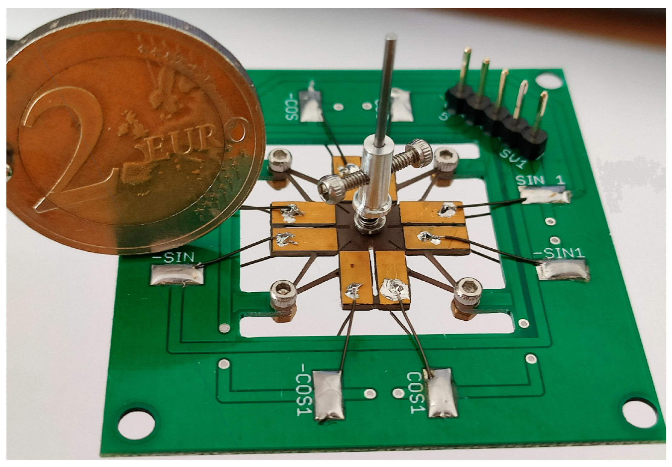
Figure 10 shows the assembled motor that is mounted into a printed circuit board.
Impedance-frequency characteristic of the motor was measured (
Figure 11). For this purpose, impedance analyzer HP 4192A (Palo Alto, CA, USA) was used. The lowest impedance of 1179 Ω was obtained at 16.35 kHz. The difference between measured and calculated resonant frequencies is 3.93%. This difference is influenced by the manufacturing errors, small variations in materials characteristics, and boundary conditions during the experimental investigation. The difference between measured and calculated impedance values is 574 Ω. The difference is mainly caused by the glue layer that was neglected during the numerical study.
The average rotation speed of the piezoelectric motor under different preload forces was measured as well. The experimental setup was built for this purpose (
Figure 12). It included a computer, four-channel function generator WW5064 (Tabor Electronics, Israel), power amplifier E-619 (PI Ceramic GmbH, Germany), four-channel oscilloscope Yokogawa DL2000 (Yokogawa, Japan) and non-contact tachometer UT 372 (Uni-T, China).
The results of measurement of an average rotation speed of the rotor under different voltages and preload forces is given in
Figure 13. The amplitude of excitation voltage was changed from 20 V
p-p to 200 V
p-p while the frequency was fixed at 16.35 kHz.
Analysis of the results shows that the rotor starts rotating at the voltage of 20 Vp-p in all cases, except when the preload force is 30.12 mN. Moreover, the average rotation speed at this preload force exhibits the lowest rotation speed starting from 140 Vp-p. Therefore, the maximum preload force of the motor is 30.12 mN.
The lowest average rotation speed was measured when the preload force of 7.64 mN was used. The lowest values were obtained when the excitation voltages were in the range from 20 Vp-p to 120 Vp-p. It can be assumed that such kinds of results were achieved because of the low friction force between the stator and rotor. The highest average rotation speed of 756.45 RPM was obtained when the preload force of 22.65 mN and voltage of 200 Vp-p was applied. The lowest rotation speed of 155.77 RPM was obtained at 20 Vp-p with the same preload force. Therefore, an average increment of the rotation speed of 3.34 RPM/V is provided by the motor. It should be noted that the standard deviation of rotation speed values, in most cases, does not exceed 15%–25% of average values.
In addition, the instantaneous maximum rotation speed of the motor was indicated. The highest instantaneous rotation speed of 972.62 RPM was obtained at 200 Vp-p voltage and 22.65 mN preload force. Compared to the average rotation speed value at these conditions, the difference is 216.17 RPM, or instantaneous rotation speed is 22.23% higher. This value does not exceed the standard deviation of average rotation speed and can be taken as the maximum rotation speed of the motor for driving at a fixed frequency of 16.35 kHz.
Table 4 shows a comparison between the proposed motor and small size rotary motors reported by other authors. The size and maximum rotation speed were chosen for comparison. It must be mentioned that the motor reported by Wang and et al. [
12] is three degrees-of-freedom motor and able to rotate rotor about three axes. On the other hand, the proposed motor can achieve from two to four times higher rotation speed, and the size is approximately seven times smaller. The highest ratio between maximum rotation speed and excitation voltage has the motor reported by Park and et al. [
14]. The proposed motor is about three times smaller, but the aforementioned ratio motor is 1.54 times lower. Furthermore, it must be noticed that the proposed motor does not need bearings for holding the rotor and can be mounted on PCB.


