Article

Effects of Different Roller Profiles on the Microstructure and Peel Strength of the Ultrasonic Welding Joints of Nonwoven Fabrics

1
Faculty of Mechanical Engineering, Ho Chi Minh City University of Technology (HCMUT), 268 Ly Thuong Kiet Street, District 10, Ho Chi Minh City 700000, Vietnam
2
Viet Nam National University Ho Chi Minh City, Linh Trung Ward, Thu Duc District, Ho Chi Minh City 700000, Vietnam
3
Faculty of Mechanical Engineering, Ho Chi Minh City University of Transport, Ho Chi Minh 700000, Vietnam
4
Science-Technology and International Cooperation Depart ment, Sao Do University, Hai Duong 03000, Vietnam
5
Research and Development Department, Murata Welding Laboratory, Osaka 5320012, Japan
6
School of Mechanical Engineering, Hanoi University of Science and Technology, Hanoi 100000, Vietnam
*
Authors to whom correspondence should be addressed.
Appl. Sci. 2020, 10(12), 4101; https://doi.org/10.3390/app10124101
Submission received: 14 April 2020 / Revised: 1 June 2020 / Accepted: 11 June 2020 / Published: 14 June 2020
(This article belongs to the Section Mechanical Engineering)

Abstract

:
Nonwoven fabrics are widely used in the textile manufacturing industry due to their advanced characteristics, such as their soft, water-repellent, recycle, ecological, and resilient functions. Nowadays, one of the innovated technologies applied to bond nonwoven fabrics is the ultrasonic welding method, due to the advantages afforded by its clean, fast, and reliable approach. In this work, isotactic polypropylene (PP) nonwoven fabrics were bonded by a continuous ultrasonic welding process. In order to consider the influence of the roller on the formation of welding joints and their mechanical properties, different roller profiles were designed, fabricated, and tested. Eight types of roller profiles corresponding to No. 1–No. 8 in the experiments were divided into four groups. After bonding, the microstructure in a typical case (i.e., No. 1) was captured by scanning electron microscopy (SEM) to examine the formation of the welding joints. Additionally, the load and the peel strength of the welding joints of all eight roller profiles were analyzed. The results showed that no welding defects, such as cracks or blowholes, were visible in the melted zone. The load depended on the area ratio(s) of the welding area (S0) to the cycling area (S1). Furthermore, it was found out that the peel strength of the welding joints with brick structures were higher than the peel strength in the case of solid line structures.

1. Introduction

Nonwoven fabrics are the most common single-fiber application for polypropylene usage in terms of sheet or web structures. These fabrics are defined as web structures made by bonding or interlocking fibers or filaments by mechanical, thermal, chemical, or solvent means. A thin layer of the nonwoven fabrics is continuously formed by the deposition process on a web belt. The uniformity and density of nonwoven fabrics can be controlled by adjusting both the velocity of the moving belt and the deposition rate [1]. The properties and structures of spunbond fabrics depend on the process parameters, such as the polymer throughput rate, the cooling and suction air speed, and also the bonding temperature [2]. Nowadays, in order to join nonwoven fabrics, various approaches such as thermal bonding, adhesive bonding, and ultrasonic welding are adopted [3].
In the thermal bonding process, the initial morphology of the nonwoven fibers significantly affects the structure and properties of the joints. For example, fibers with high molecular orientation and crystallinity tend to form a weak and brittle bond due to the lack of polymer flow. On the other hand, fibers with lower tenacity and higher elongation at break result in better bonding and higher fabric tensile properties [4]. In order to clarify the issues related to the bonding temperature process, Gajanan et al. investigated thermal bonding conditions, involving the welding area, size, and temperature. The results showed that the strength of a thermal welding joint increased with the expansion of the welding area and size. However, the welding strength and the bending length varied according to the temperature distribution [5]. Nataliya et al. studied the strength of thermal calendared joints using islands-in-the-sea (I/S) fibers. Nylon-6 (N6) and polyethylene (PE) of bicomponent structures were used as the islands and the sea in the I/S bicomponent fibers, respectively. The results indicated that the strength of the thermally bonded N6-PE fibers was higher than that of the original fibers [6]. However, the thermal bonding process is complex, and it is easy to cause a lack of the temperature for melting at the central region of the bond [7].
In order to improve the quality of the bonding structures, adhesive bonding technology has been applied instead of conventional thermal bonding processes. In adhesive bonding technology, ultraviolet curable adhesive is utilized to obtain better properties than when using structural adhesives [8]. However, the quality of the bonding structure (i.e., the mechanical properties) still has some issues, such as a low operating temperature and low shear stress [9].
To overcome these troubles, an innovative bonding technology using ultrasonic vibration has recently been researched and developed. In bonding by ultrasonic vibration, the mechanical vibrations combined with the high pressure can create enough temperature for softening nonwoven fabrics, causing molecular diffusions and cooling down to form welding joints [10]. In previous papers, the tensile strength and elongation at break values of ultrasonic welding joints were investigated according to the fabric’s area density and row rollers. The results implied that an increase of the area density of the fabric and the row rollers can lead to an increase in the tensile strength. In addition, it was highlighted that the elongation at break values are proportional to the density and row rollers [11]. In another work, Shi et al. estimated the possibility of ultrasonic welding on textile fibers. In this work, an ultrasonic welding system with a longitudinal horn moving in the vertical direction was utilized, after which, the mechanical force was applied on multilayers of the fabrics over the anvil. The results presented that an increase in the welding time and pressure can increase the joint strength initially, but afterward, the strength decreases further. Meanwhile, with an increase in the vibration amplitude, the strength of welding joints can be enhanced [12]. In a recent study, ultrasonic welding was applied for bonding sailcloth using different types of anvil wheels. Under the welding conditions of this paper, the bonding strength of the bonding joints can be increased with suitable engraving, speed, and amplitude of the ultrasonic system [13]. Meanwhile, in the case of polyethylene terephthalate fabrics, the sealing time and welding pressure can also affect the bonding strength, as shown in [14].
For improving the quality of the ultrasonic welding process for fabrics, some of the key parameters have been investigated. In a recent paper, the welding time, holding time, mechanical force, and anvil gap were considered in detail [15]. Furthermore, because horn surface amplitude is one of the most important factors that greatly affects joint quality, the uniformity of the amplitude of the horn has been investigated by both simulations and experiments [16,17]. The results presented that the maximum amplitude occurs at the nodal region, causing high stress levels and leading to horn crack. Thus, the amplitude was controlled at less than 77 µm within the safety region to prevent damage to the horn and the welding apparatus [18].
One of the most frequently used polymer materials owing to its low price, good processability, and mechanical properties is polypropylene (PP), which is semi-crystalline thermoplastic. As indicated above, making nonwoven fabrics from PP materials requires to assemble staple fibers or infinitely continuous filament fibers on top of each other to be bonded via a mechanical, thermal, or chemical process [19]. Recently, ultrasonic welding technology has been considered as an ideal approach to bond PP fabrics. In a recent paper, Floyd et al. studied the ultrasonic bonding of various types of fibers, which, for example, included PP materials and N6. They found that an impressive feature of the many fabrics produced was their superior softness over comparable products produced by calendar bonding. They also found that high melting point fibers such as N6 were difficult to bond in comparison to PP [20]. In another study, it was reported that better bonding was achieved by using polypropylene–polypropylene and polyester–polyester fabrics [21].
Even though ultrasonic welding is a promising technology for bonding nonwoven fabrics, there are still very few research papers published in the open literature in this field, especially for PP nonwoven fabrics. Furthermore, the mechanism of this technology is not yet understood fully. In order to clarify these issues further, this experiment focused on determining the influence of the ultrasonic horn shape on the formation of welding joints in the case of PP nonwoven fabrics using a continuous ultrasonic welding approach. Scanning electron microscopy (SEM) images of the bonded joints at different positions and directions were taken to investigate the interfacial microstructure and the bond locations of the fabrics. Moreover, the effects of the roller engravings on the peel strength are also discussed in detail.

2. Experimental Design and Materials

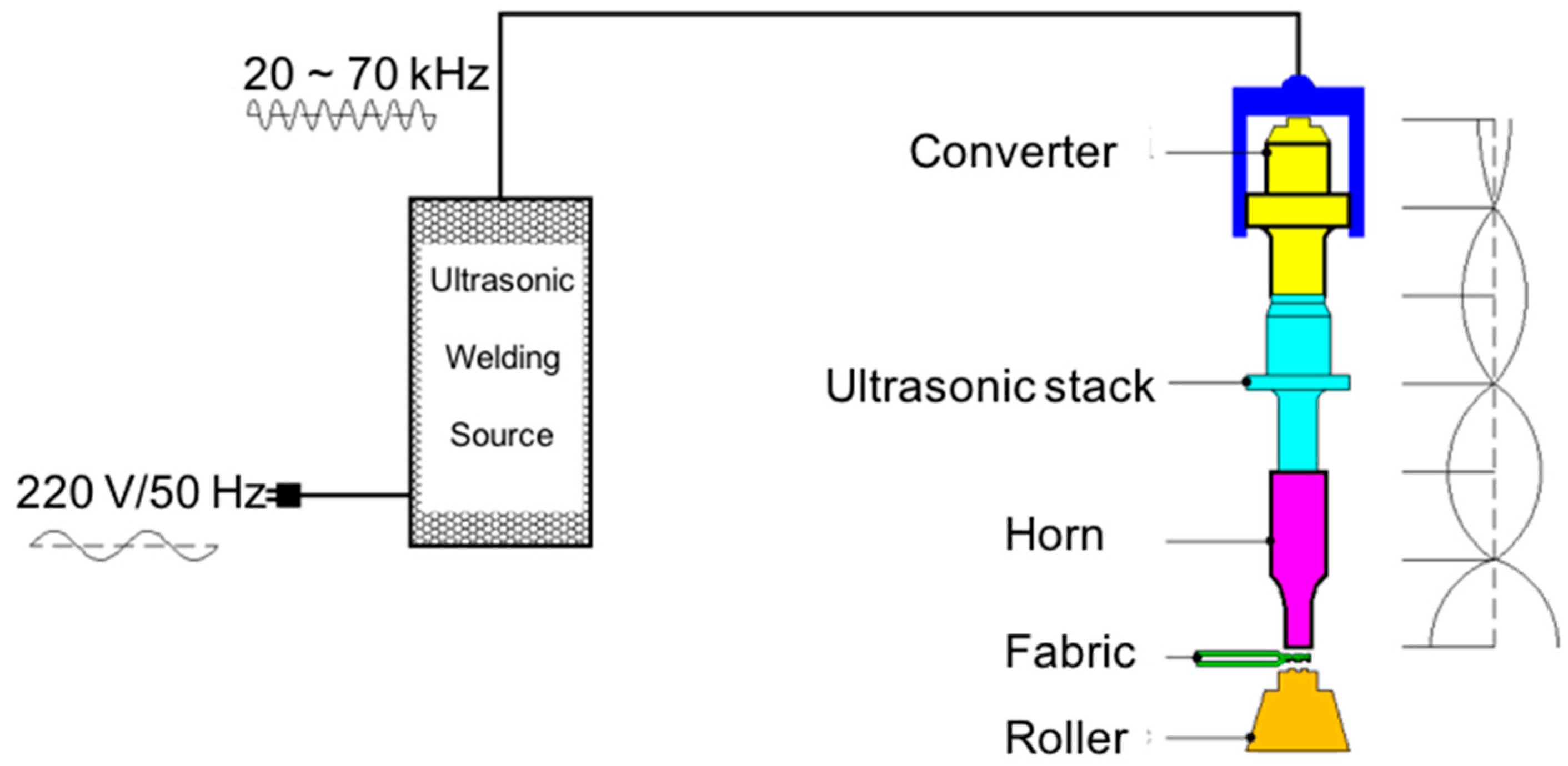
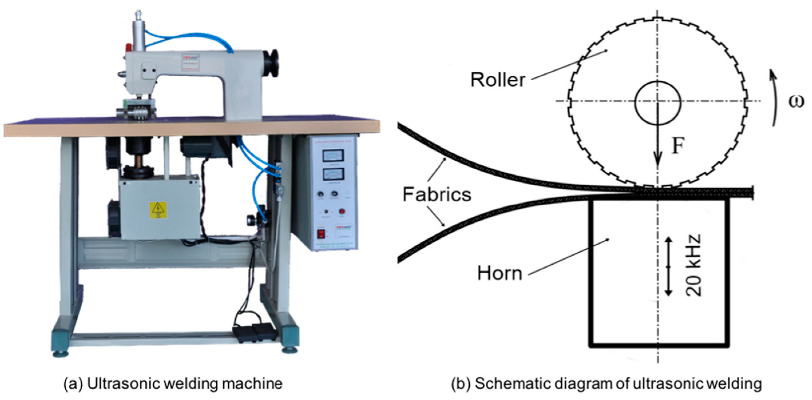
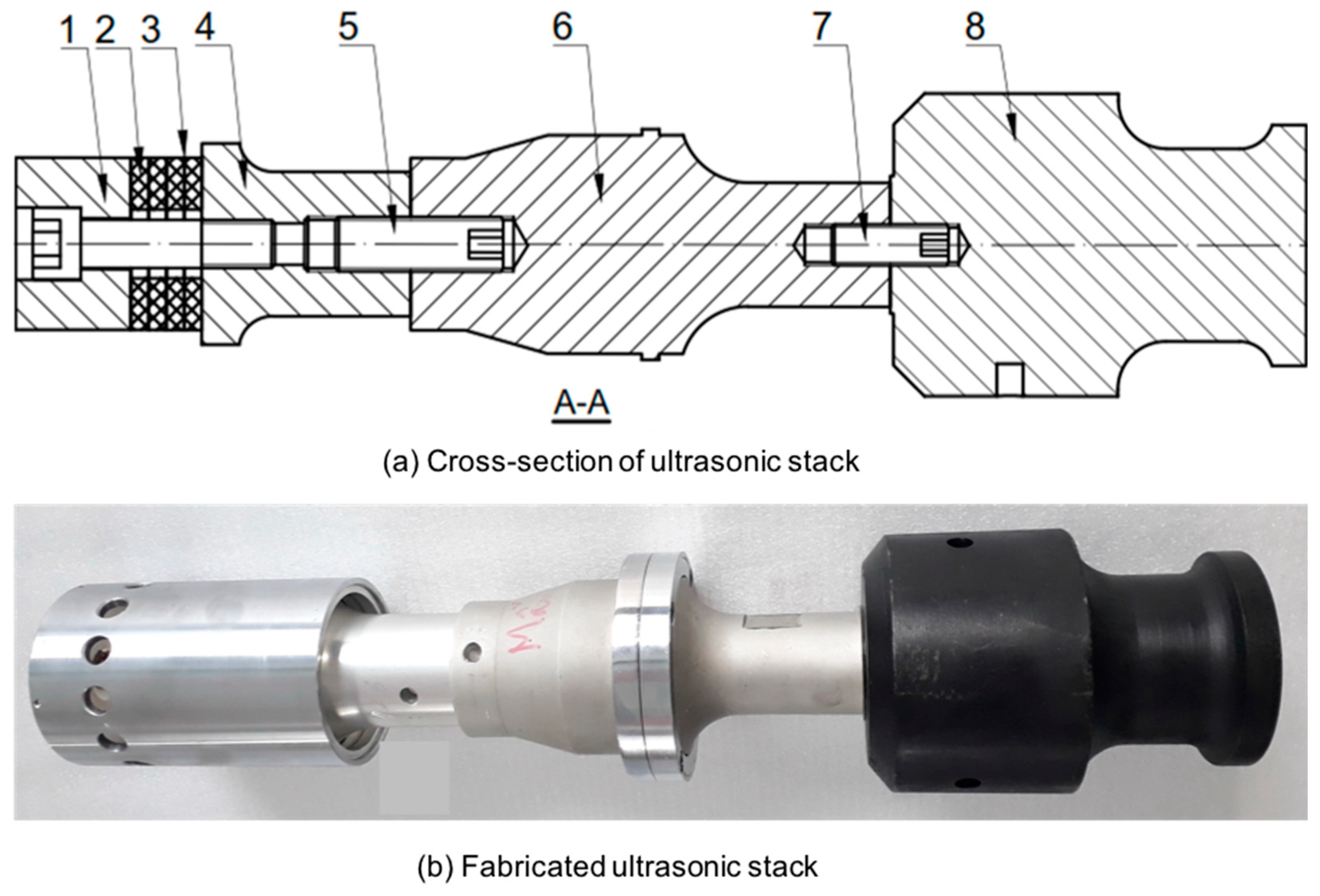
2.1. Common Welding Apparatus and Base Material
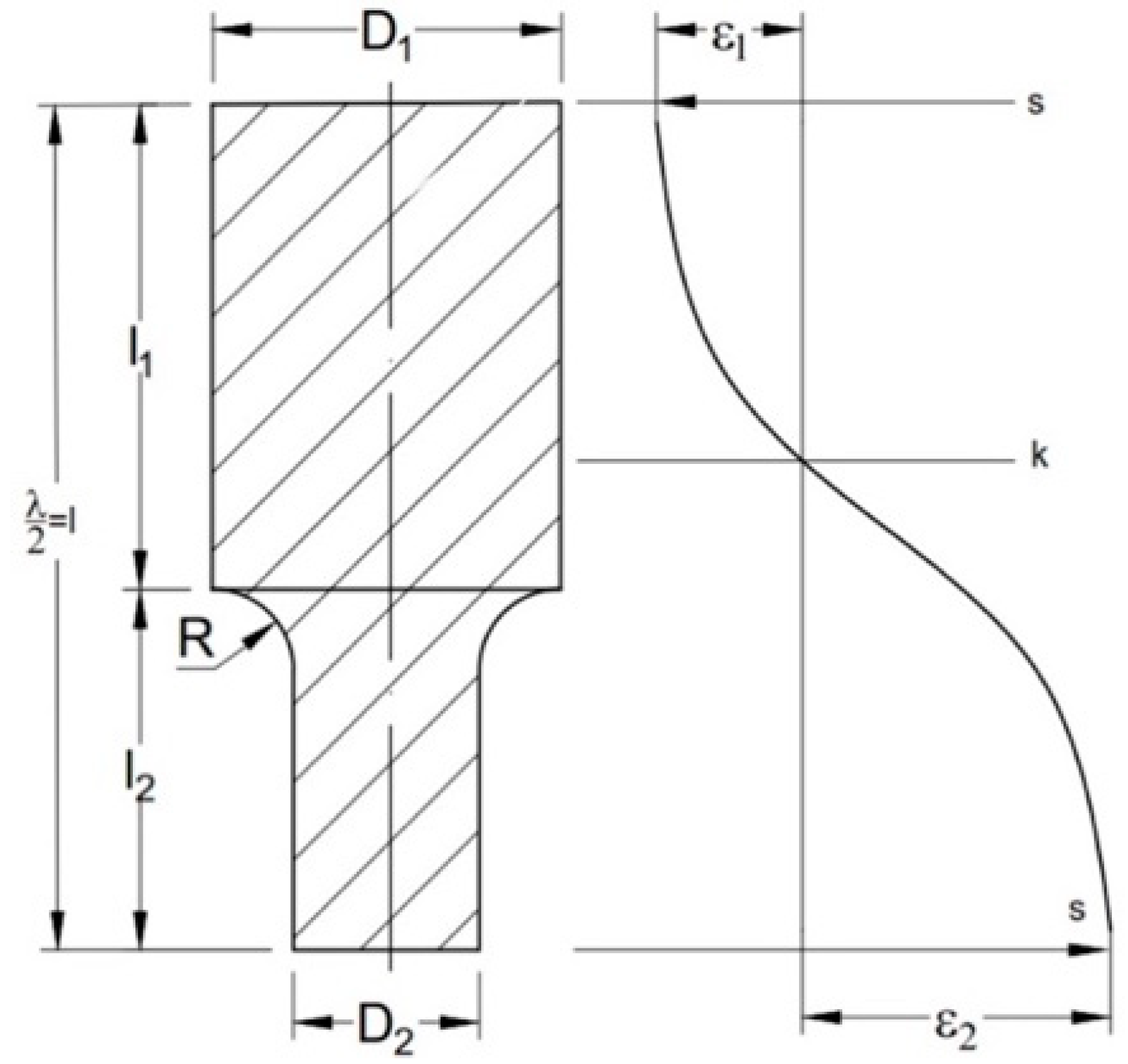
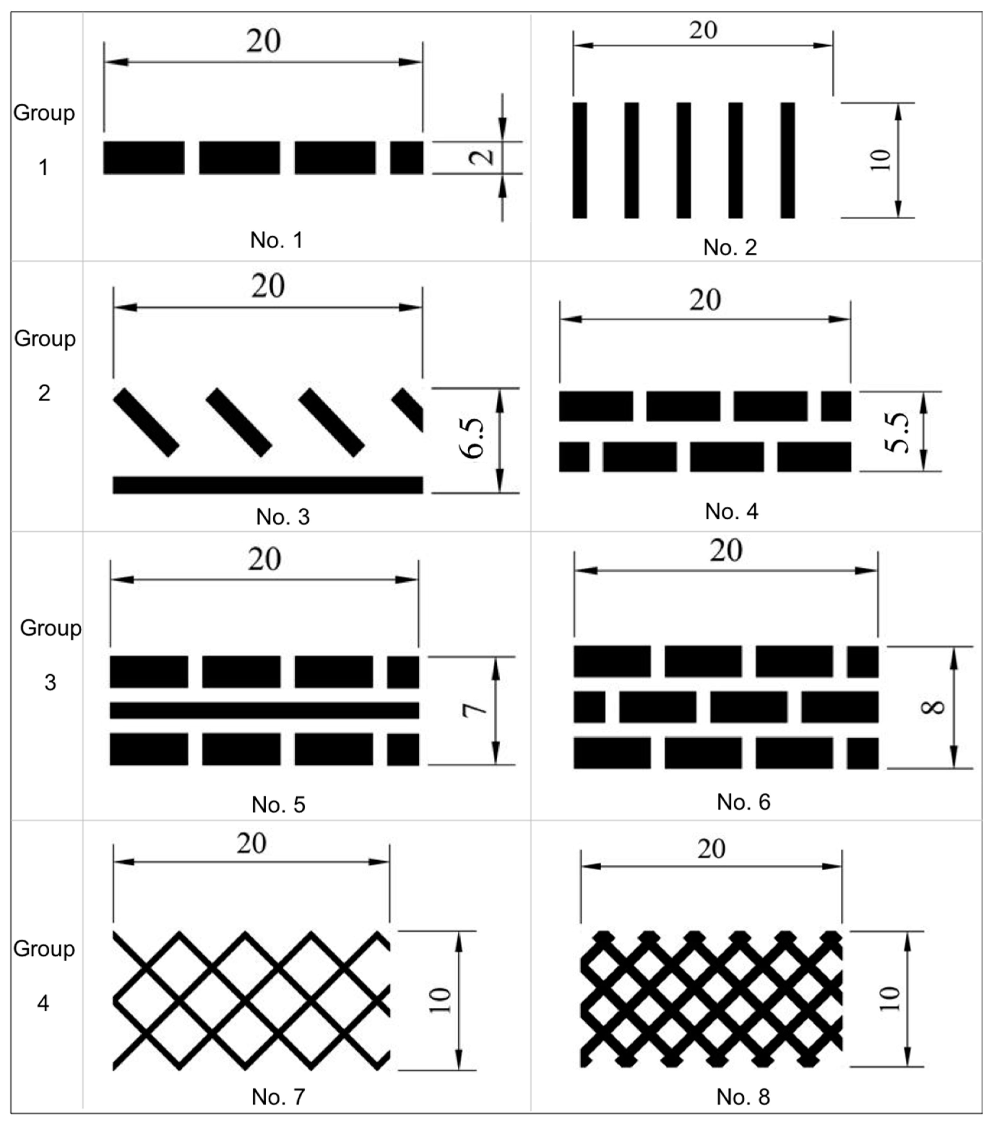
A real image and a schematic diagram of an ultrasonic welding equipment for bonding fabrics are shown in Figure 1 and Figure 2. Generally, this equipment consists of a welding source, a stepped horn, an ultrasonic stack, a roller, and fabric (base material).
In this experiment, the main equipment was the continuous ultrasonic welding machine (Model VS2020, Viet Nam Ultrasonic Equipment Company LTD, Ho Chi Minh, Vietnam) with an inner roller and pneumatic cylinder as portrayed in Figure 2a. The frequency and power of the machine were set at 20 kHz and 1200 W, respectively. The maximum value of the mechanical vibration on the surface of the ultrasonic horn was 60 microns. The roller speed was controlled at 6 m min. The air pressure was set up at 3 bar. The inner diameter of the pneumatic cylinder was 40 mm. The roller was mounted to a mechanical frame and rapidly changed; its width was smaller than the diameter of the ultrasonic horn. A schematic diagram of the ultrasonic welding process is presented in Figure 2b. In this case, the ultrasonic horn is fixed and the roller is rotated directly on the horn surface under mechanical force F.
The base metal for the bonding was polypropylene spunbond fabrics of 80 gsm. The mechanical properties of the PP fibers and the PP nonwoven fabric are listed in Table 1 and Table 2.
In this paper, a simple type of stepped horn was utilized, as shown in Figure 3. Here, the horn is characterized by parameters D1 and D2, l, and R, where D1 and D2 refer the diameters of the two ends of the bar, l is the total length of the horn, and R is radius at the step. In this experiment, the diameters D1 and D2 of the horn were selected as 90 mm and 70 mm, respectively. The values of the main parameters of the horn, including the velocity of the sound in a continuous solid medium of 500 m s−1, a Poison ratio of 0.28, a modulus of elasticity of 200 GPa, and a working frequency of 20 kHz, were set up. Under the strong friction between the horn and the roller, the working surface of the ultrasonic horn in this case must have high wear resistance to reduce breaks and increase the life. Therefore, SKD11 tool steel (Japanese industrial standards (JIS)) was selected for making the horn. The chemical composition is described in Table 3.
Figure 4 represents a typical example of the ultrasonic stack utilized in this experiment. The untrasonic stack includes back mass (1), Piezoelectric rings (2), copper electrodes (3), front mass (4), booster (6), bolt (7), and stepped horn (8).

2.2. Roller Design

In order to study the formation of the welding joints, the following patterns for the roller were designed, from simple to complex, as indicated in Figure 5. Eight patterns corresponding to No. 1–No. 8 were fabricated in this work. The patterns were divided into four groups with different welding areas, geometries, and symmetries. Group one was designed with the simplest shape, the smallest welding area, and only one-line geometry (No. 1 and No. 2). Group two was designed with a simple shape, a medium welding area, and nonsymmetrical geometry (No. 3 and No. 4), where No. 3 included a solid line in order to test the continuous welding line. In group three, the number of rows and the size of the welding area were increased (No. 5 and No. 6), and a solid line was intentionally inserted between two dashed lines. Group four was designed with a complex shape, a large welding area, and symmetrical geometry (No. 7 and No. 8).

3. Experimental Results and Discussion

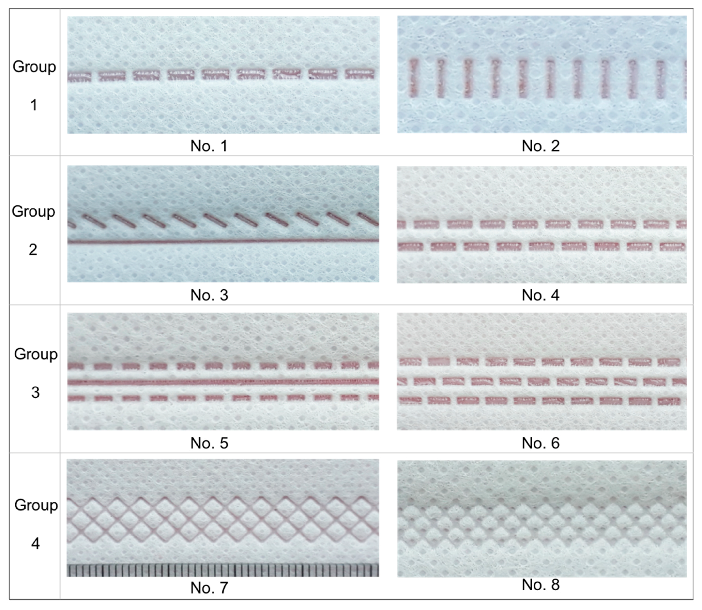
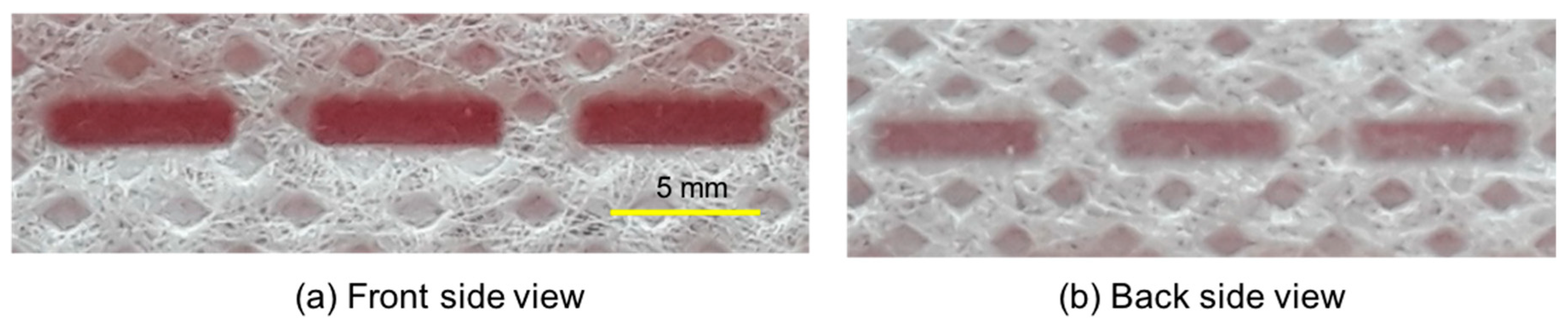
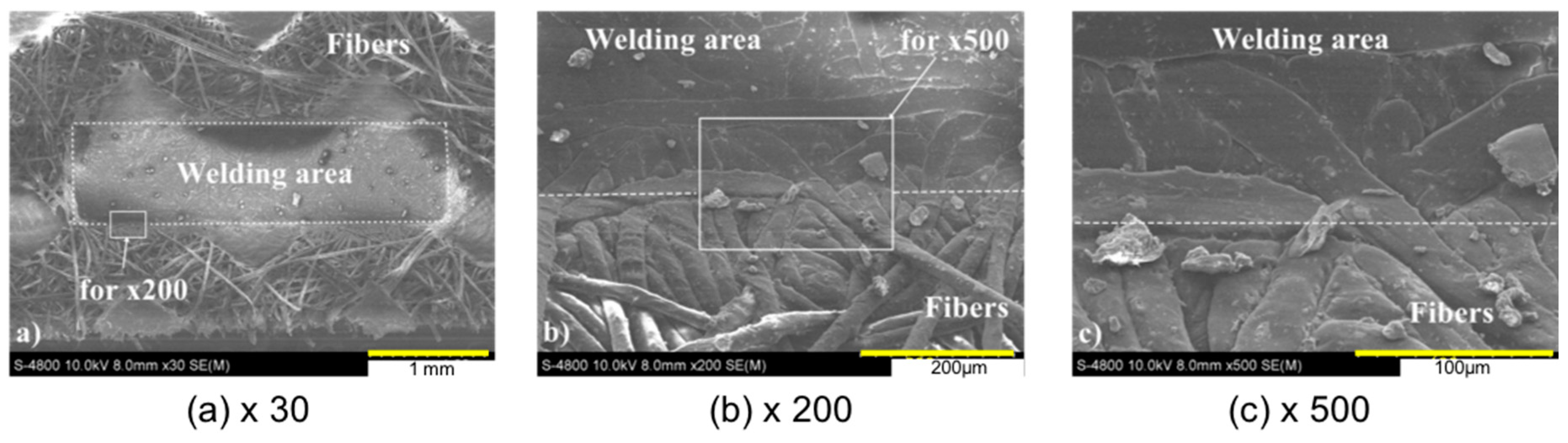
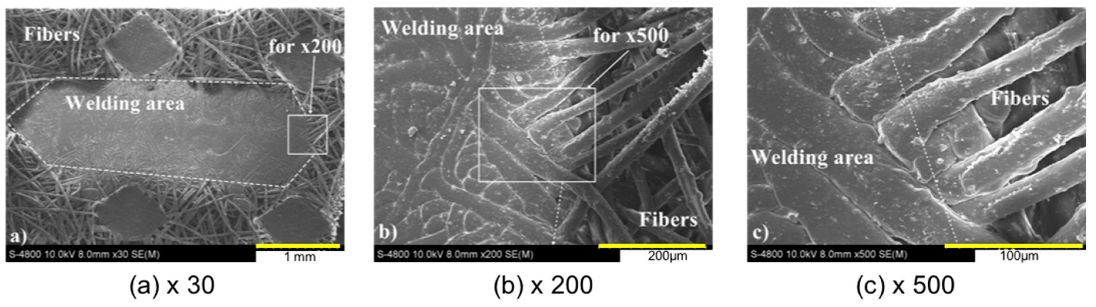
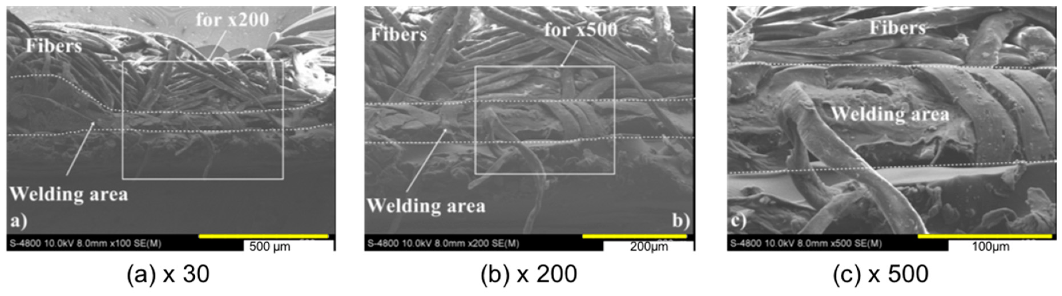
3.1. SEM Images of the Welding Joints

The welding joint images of the front of the eight patterns (No. 1–No. 8) are shown in Figure 6. As can be seen in this figure, the welding joints look sound without incomplete weld seams or deviation of the welding profile in comparison to the designed horn profiles. The profile of the welding bead is similar to the profile of the horn head. In order to examine the quality of the welding joints, only No. 1 was considered in detail. Magnification images of the front side, backside, and cross-section were captured by SEM. The results can be seen in Figure 7, Figure 8, Figure 9 and Figure 10.
Figure 7 shows the images of the front side and the backside, where the center zone is the welding seam. Because the roller with its specific pattern rotated on the fabric, the front side of the ultrasonic welding joints was compressed, as indicated in Figure 7a. Meanwhile, the fabric slid on the flat surface of the horn, and thus, the backside of the ultrasonic welding joints was flat (Figure 7b).
It is well known that a mechanical vibration of ultrasonic frequency, with specific amplitude and mechanical force, from the roller can create heat at the interface of two fabrics. The heat is increased rapidly in the case that either the force increases or the welding speed decreases. As a result, the fabrics at the interface melt and solidify quickly.
In order to investigate the welding quality, SEM images were taken at the boundary between the welding area and the base metal (i.e., fabric fibers) of the welding joints, both of the front side (Figure 8) and of the backside (Figure 9). Figure 8a shows the entire welding joint of the one-line engraving taken from the front view. The boundary between the welding area and the base fabric is relatively clear. The fibers in the welding area are compressed lower than the fabric surface. Welding defects can be found in the welding zone, since the base fabric is not of a homogenous material. Some fabric fibers are totally melted, but others still exist (as incompletely melted). This can be explained by the fact that the thickness of the fabrics is not uniform, and heat is not generated equally over the welding area. Figure 8b,c presents the structure at the edge of the welding boundary, where half of it is the welding area and the other half is the base metal (i.e., PP nonwoven fabric). A smaller size illustrates the structure of the base metal fiber, while a larger size expresses the welding region. The shapes of the welded fibers are changed due to the compression force and the ultrasonic heat. However, the fibers are not broken or cracked, and remain as continuous media. As a result, these structures can support the creation of the high strength required for welding joints.
Figure 9 exhibits the entire welding joint of the one-line engraving taken from the backside view. As implied in Figure 9a, the rectangular shape is formed by the ultrasonic welding after using one-line engraving pattern. However, the four diamond shapes are generated by the heat roller during the fabric formation process. The edges of the rectangular shape between the welding area and the base fabric are very blurry. This can be explained by the fact that the backside of the base fabric directly contacted the fixed ultrasonic horn instead of the roller pattern. Inside the welding zone, some fibers are melted, while others are not; however, the region of the melted fibers is larger. The fibers at the boundary region are melted differently, which means that the heat caused by ultrasonic vibration varied along the edges. However, other defects are not seen in the welding area. Figure 9b,c shows the edge region between the welding area and the base fabric. The fibers on the left side are compressed, melted, and bond together clearly. On the other hand, the fibers on the right side still retain their shape and structure. Similar to the view from the front side view, the fibers in the edge region are not broken. Therefore, they can form the high strength of the welding joints.
Figure 10 shows SEM images at a cross-section of the welding joints. At magnification ×100 (Figure 10a), the concave shape caused by the roller engraving of the upper fabric can be clearly observed. The curvature between the surface of the upper fabric and the surface of the welding area can be seen. This structure increases the linkage between the fibers of the upper fabric and the fibers of the welding region. In the welding area, some fibers are totally melted and solidified into a uniform medium, while the others are compressed and partially melted, as indicated in Figure 10b. In addition, the solidified region can be clearly seen with larger magnification (Figure 10c).

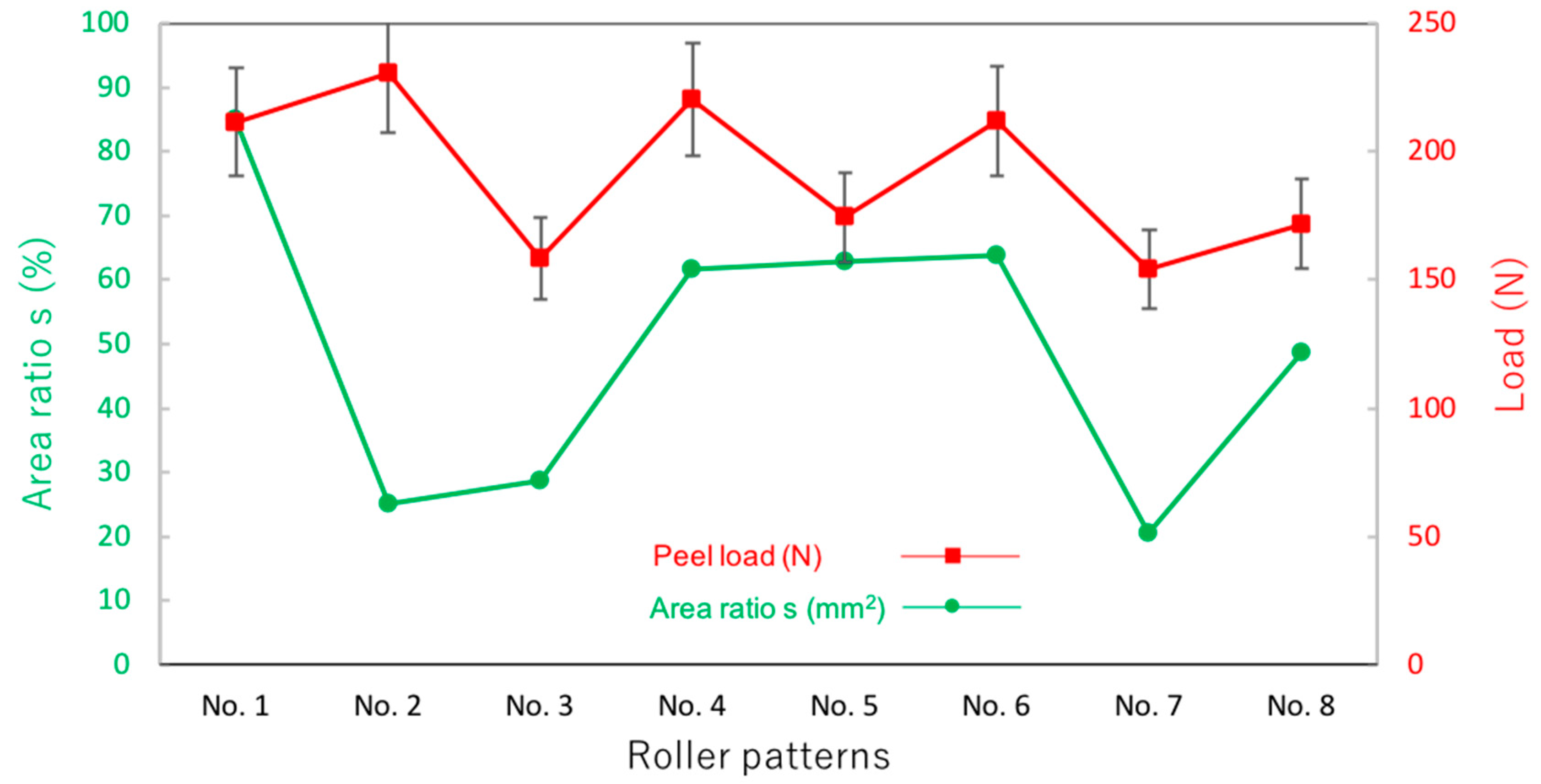
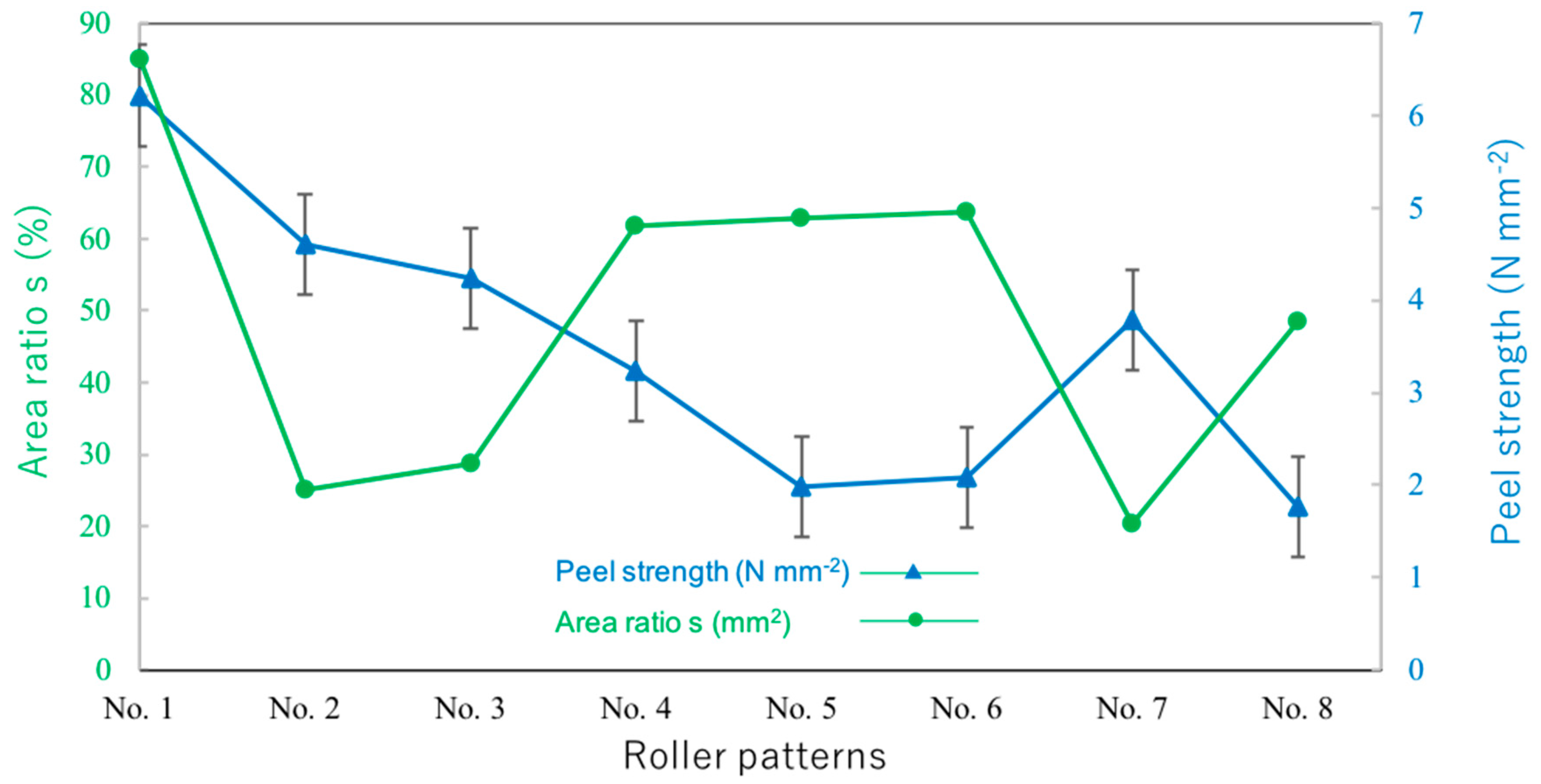
3.2. Peel Strength of the Welding Joints

Peel strength is generally used to measure the bond strength of a material, typically the adhesive and the thermal bonding. Because the area ratio (s) of the welding area (S0) to the cycling area (S1) is an important factor when considering the relationship between roller patterns and peel strength, it is presented first. The definition of the welding area (S0) to the cycling area (S1) is as follows: The welding area (S0) is generally defined as the solid area in the pattern, while the cycling area (S1) is the rectangular area covering the welding area in one cycle. For easy calculation, the cycle was set as 20 mm in length. The area ratio of the welding area to the cycling area in the patterns was mostly different in the welding area and the geometry. As a result, a matrix of all of the roller profile cases is listed in Table 4.
In order to investigate the influence of the different roller profiles on the load and the peel strength of the welding joints, a strength test of all of the designed patterns (No. 1–No. 8) was conducted. Four samples of each pattern were welded and tested to obtain the average value of the load and the peel strength. The average load and the average peel strength of the four groups were drawn, and are presented in in Figure 11 and Figure 12, respectively. According to the groups, the load and the peel strength can be compared, which shows that generally, the load distribution is opposed to the strength distribution.
In the case of the solid line of the welding joints in group one, the load of No. 2 is larger than the load of No. 1. This is because the welding joint of No. 2 is larger than that of No. 1. The load of No. 4 is significantly larger than that of No. 3. This can be explained by the fact that the solid line in pattern 3 created a continuous welding area, and it can be seen in the SEM image (Figure 8a) that inside the welding area, the fibers are mostly melted and solidified. Therefore, the linkage area between the fibers and the solidified area around the edges of the No. 3 is smaller than that of No. 4. This explanation can also be used to describe the reason why the load of pattern 6 is larger than that of No. 5. The load of No. 7 and 8 is almost same due to only a slight change in the thickness of the pattern lines. According to area ratio as described above, No. 2 offers the highest load with the smallest area ratio (s). Meanwhile, No. 7 provides the lowest load with a large area ratio (s). From the results above, it can be considered that the load is proportional to the area ratio and it depends on the roller profile. In summary, the maximum load of the ultrasonic welding joints can be obtained with No. 2, and a brick structure (No. 4 and No. 6) offers a greater load than the other structures. Meanwhile, patterns with a solid line (No. 3, No. 5, and No. 7) show less load than the others.
Generally, the peel strength is decreased from No. 1 until No. 5. In No. 5 and No. 6, it is mostly unchanged. The peel strength is lower in No. 8 in comparison to No. 7. Even though the load is maximal (230.39 N) in No. 2, the peel strength is maximal in No. 1 (6.22 MPa). This can be explained by the fact that the welding area in No. 2 is much larger than in No. 1. The peel strength in the case of No. 3 is higher than that in No. 4. This is because the welding area in No. 4 is much larger than in No. 3. Even though the load is lowest (154.31 N) in No. 7, in comparison to the other cases, the peel strength is higher than that in No. 4 to No. 6 and No. 8. From the above results, it can be considered that the load and the peel strength interact with the welding area (S0) and the area ratio (s); in other words, they depend on the roller profile.

4. Conclusions

In this research, eight roller patterns divided into four groups were fabricated and utilized to investigate the properties of welding joints. On this basis, the following main conclusions can be drawn:
(1)
No welding defects were seen in the SEM images of the front side, the backside, or a cross-section of the welding joints.
(2)
The peel load distribution was opposed to the strength distribution in all cases of the fabricated roller profiles.
(3)
The area ratio (s) was highest in the case of No. 2 (approximately 89%) and lowest in the case of No. 7 (approximately 27%).
(4)
The maximal load (approximately 230.39 N) occurred in the case of No. 2, while the minimal value (approximately 154.31 N) occurred in the case of No. 7.
(5)
The maximal peel strength of 6.2 N mm−2 occurred in the case of No. 1, and the lowest tensile strength of 1.8 N mm−2 occurred in the case of No. 8.
(6)
Both the load and the peel strength were proportional to the welding area and the area ratio.
(7)
In the case of No. 2, even though the load was the highest (approximately 230.39 N), the peel strength was lower than that of No. 1.

Author Contributions

M.N.H. and N.H.L. contributed to the project design; L.Q.T. performed all experiments and data processing; A.N.V. and T.-h.N. wrote and revised the manuscript. All authors participated in the discussion of the results and guided the writing of the article. All authors have read and agreed to the published version of the manuscript.

Funding

This research was funded by Vietnam National University Ho Chi Minh City (VNU-HCM) under grant number B2019-20-08.

Conflicts of Interest

The authors declare that there are no conflict of interest regarding the publication of this paper.

References

  1. Hosun, L. A review of spun bond process. J. Tex. App. Technol. Man. 2010, 6, 1–13. [Google Scholar]
  2. Rammohan, N.; Gajanan, S.B. Effect of Processing Conditions on the Structure and Properties of Polypropylene Spunbond Fabrics. J. App. Poly. Sci. 2005, 98, 2355–2364. [Google Scholar]
  3. Mahmut, K. Analysis of Ultrasonic Seam Tensile Properties of Thermal Bonded Nonwoven Fabrics. J. Eng. Fib. Fab. 2014, 9, 2014. [Google Scholar]
  4. Subhash, C.; Gajanan, S.B.; Joseph, E.S.; Sanjiv, M. Structure and properties of polypropylene fibers during thermal bonding. Thermo. Acta 2001, 367, 155–160. [Google Scholar]
  5. Gajanan, S.B.; Praveen, K.J.; Joseph, E.S. Thermal bonding of polypropylene nonwovens: Effect of bonding variables on the structure and properties of the fabrics. J. App. Poly. Sci. 2004, 92, 3593–3600. [Google Scholar]
  6. Nataliya, F.; Svetlana, V.; Behnam, P. Strength Optimization of Thermally Bonded Spunbond Nonwovens. J. Eng. Fib. Fab. 2007, 2, 38–48. [Google Scholar]
  7. Warner, S.B. Thermal Bonding of Polypropylene Fibers. Tex. Res. J. 1989, 59, 151–159. [Google Scholar] [CrossRef]
  8. Adams, R.D.; Comyn, J.; Wake, W.C. Structural adhesive joints in engineering-Ultrasonic welding of plastics and polymeric composities. Spring Sci. Busi. Media 1997, 12, 296–312. [Google Scholar]
  9. Skander, L.; Steven, B.W. Adhesive Point-Bonded Spunbond Fabrics. Tex. Res. J. 2005, 75, 63–72. [Google Scholar]
  10. Zhentao, M.; Bhuvenesh, C.G. Studies on the Process of ultrasonic bonding of nonwovens: Part 1—Theoretical Analysis. Int. Nonwo. J. 2001, 2, 38–47. [Google Scholar]
  11. Mahmut, K.; Suleyman, I.M. Analysing effect of the factors on ultrasonic seam tensile properties of nonwoven fabrics by Nested Anova Design. Inter. J. Cloth. Sci. Technol. 2015, 27, 803–817. [Google Scholar]
  12. Weihua, S.; Trevor, L. Mechanisms of ultrasonic joining of textile materials. Int. J. Cloth. Sci. Technol. 2000, 12, 331–350. [Google Scholar]
  13. Edita, V.; Zeljka, J. Investigation of the strength of ultrasonically welded sails. Int. J. Cloth. Sci. Technol. 2007, 19, 204–214. [Google Scholar]
  14. Subhas, G.; Renuka, R. Ultrasonic sealing of polyester and spectra fabrics using thermo plastic properties. J. App. Poly. Sci. 2009, 113, 1082–1089. [Google Scholar]
  15. Jones, I. Ultrasonic and dielectric welding of textiles Joining Textiles, Principles and Applications; Wood. Pub. Seri. Tex.: Cambridge, UK, 2013; pp. 374–397. [Google Scholar]
  16. Lucas, M.; Smith, A.C. Redesign of Ultrasonic Block Horns for Improved Vibration Performance. J. Vib. Acous. 1997, 119, 410–414. [Google Scholar] [CrossRef]
  17. Nguyen, T.H.; Quang, T.L.; Tran, C.L.; Nguyen, H.L. Investigation the Amplitude Uniformity on the Surface of the Wide-Blade Ultrasonic Plastic Welding Horn. IOP. Conf. Ser. Maters. Sci. Eng. 2017, 241, 012023. [Google Scholar] [CrossRef] [Green Version]
  18. Rani, M.R.; Prakasan, K.; Rudramoorthy, R.; Rudramoorthy, R. Studies on thermo-elastic heating of horns used in ultrasonic plastic welding. Ultrasonics 2015, 55, 123–132. [Google Scholar] [CrossRef] [PubMed]
  19. Floyd, K.; Ozsanlav, V. Application of Ultrasonics in the Nonwoven Industry. EDANA's 1988 Nordic Nonw. Sym. 1988, 13, 120. [Google Scholar]
  20. Manal, A.S.; Mona, M.N. A comparative study of assembling methods of nonwoven bags traditional sewing and welding seam. Int. J. Gene. Eng. Technol. 2016, 5, 7–22. [Google Scholar]
  21. Shi, W.; Little, T. Ultrasonic Joining of Textile Materials. Inter. J. Cloth. Sci. Technol. 2000, 12, 331–350. [Google Scholar] [CrossRef]
Figure 1. A schematic diagram of a common ultrasonic welding equipment.
Applsci 10 04101 g001
Figure 2. Ultrasonic welding equipment and schematic diagram. (a) Ultrasonic welding machine, (b) Schematic diagram of ultrasonic welding.
Applsci 10 04101 g002
Figure 3. A model of the stepped horn.
Applsci 10 04101 g003
Figure 4. An example of ultrasonic stack. (a) Cross-section of ultrasonic stack, (b) Fabricated ultrasonic stack.
Applsci 10 04101 g004
Figure 5. Designation of the roller patterns.
Applsci 10 04101 g005
Figure 6. The welding joint images of the eight patterns (No. 1–No. 8).
Applsci 10 04101 g006
Figure 7. Nonwoven fabric after ultrasonic welding of No. 1 case. (a) Front side view, (b) Back side view.
Applsci 10 04101 g007
Figure 8. Scanning electron microscopy (SEM) images of the ultrasonic welding joints taken from the front with magnification of (a) ×30, (b) ×200, and (c) ×500.
Applsci 10 04101 g008
Figure 9. SEM images of the ultrasonic welding joints taken from the backside with magnification of (a) ×30, (b) ×200, and (c) ×500.
Applsci 10 04101 g009
Figure 10. SEM images of the ultrasonic welding joints taken at a cross-section with magnification of (a) ×100, (b) ×200, and (c) ×500.
Applsci 10 04101 g010
Figure 11. Relationship between the load and the area ratio with different patterns.
Applsci 10 04101 g011
Figure 12. Relationship between the peel strength and the area ratio with different patterns.
Applsci 10 04101 g012
Table 1. The mechanical properties of the PP fibers (PA6-RM-14-030-supported by Lanxess energizing Chemistry Co., Ltd., Cologne, Germany).
Density (kgm3)Elongation at Break (%)Tenacity (cN/tex)Fiber Crimp (cm)Shinkage (%)Yield Strain (%)Softening Point (°C)Melting Point (°C)
114016019141.1620140–150160–175
Table 2. The mechanical properties of the PP nonwoven fabric fibers.
Calendar Temperature (°C)Calendar SpeedPressure
14518~25 gm−3 at 200 m min−1
30 = 50 gm−3 at 140 m min−1
80
Table 3. The chemical composition of the SKD11 tool steel (JIS) for fabricating the horn.
ComponentCSiMnMoCrFe
%1.4–1.60.17–0.370.5–0.80.98–11Bal.
Table 4. Welding area (S0), cycling area (S1), and area ratio (s) of the designed patterns.
No.12345678
S0 (mm2)345037.3688810240.797.1
S1 (mm2)40200130110140160200200
s = S0/S1 (%)85.025.028.761.862.963.820.448.6

