1. Introduction
With the development of the manufacturing industry, computer numerical control (CNC) machine tools are also toward the goal of high reliability and high precision, and for industry, such as aviation, aerospace, shipping, and energy, higher requirements are put forward for the manufacturing precision of related parts, especially the super large parts. The processing of super-large parts is mainly completed on the ultra-heavy duty machine tool [
1], and the indexing ability of the rotary table determines the precision level of the workpiece [
2].
In a vertical machine tool, the C-axis is the axis rotating around the spindle of the table. The rotary feed movement of the spindle can be driven by a servo motor or a spindle motor combined with an encoder. C-axis indexing positioning and other feed axis linkage can achieve arbitrary trajectory processing [
3]. The development of the C-axis indexing feed system of CNC machine tools is mainly divided into the following stages [
4]. The traditional C-axis positioning is driven by a single motor drive mechanism and with the damping clamping device. The transmission gear meshes with the large gear ring on the spindle of the table, which drives the table to rotate. At the same time, the detection element detects the speed and feeds back to the control system. By correcting the motor parameters, the speed and angle are controlled to form a closed-loop control. The transmission precision of the mechanism is improved, and the indexing and positioning function of the feed system is realized [
5,
6,
7]. Because of the use of a single servo motor with a single drive chain, the damping clamp device is usually only relied on to eliminate the tooth clearance. Its driving accuracy is low and positioning accuracy is poor.
Under the condition of higher demand for C-axis indexing feed accuracy, how to effectively reduce or eliminate the clearance error through the design of the driving system is the main problem for improving the positioning accuracy of the C-axis. At present, the general method is to use a double drive chain to eliminate the clearance. The drive system consists of two identical gear mechanisms that are driven by a servo motor. After reducing the speed of the reduction mechanism, one of the independent shafts is selected and a constant pressure oil cylinder and a spring set are installed at both ends of the shaft. Through the helical gear axial movement, the end gears of the two gear mechanisms are meshed with the positive and negative meshing surfaces of the main shaft’s large gear ring, respectively, so as to eliminate the blank path error of the whole transmission chain [
8,
9,
10]. Although this transmission mechanism can effectively eliminate the blank path error that is generated by the side clearance of the end gear, it cannot eliminate the gear side clearance of the front part of the transmission chain, which will still have a great impact on the indexing and feeding accuracy of the whole system.
The requirements for dynamic performance and tracking accuracy of the system in practical applications cannot be met due to the presence of tooth clearance, friction dead zone, and other non-linear links in the mechanical drive mechanism of the above two C-axis servo control systems. In addition, due to the limited motor capacity, it is difficult to realize the high-power output in the practical application of ultra-heavy machine tools only by the transmission mechanism driven by a single motor. In view of the above problems, the current ultra-heavy machine tools mainly adopt the dual servo motor to achieve the C-axis rotation and indexing feed function. The dual servo motor adopts the master-slave control function, with the independent drive chain to eliminate the tooth side clearance [
11,
12,
13,
14]. This kind of transmission structure can not only meet the power demand of the ultra-heavy machine tool, but also use the control means to eliminate the lateral clearance of gear teeth of the transmission mechanism and improve the positioning accuracy. However, how to establish a general dynamic model to reflect the gear clearance in the actual work and how to optimize the control parameters of the dual servo motor system are still urgent problems to be solved due to the different types of machine tools and processing objects.
In view of the characteristics of ultra-heavy duty vertical machine tool’s rotating table bearing large load, this paper designed a two-servo motor driven table, and analyzed the principle and process of eliminating the gear tooth clearance when C-axis indexing positioning. The dynamic model of dual servo motor driving system and the optimization of control parameters were proposed. The feasibility and superiority of the presented method were demonstrated by the experiments.
2. Principle of Gear Clearance Elimination Using Double Servo Motor
The heavy-duty vertical milling machine (Qiqihar Heavy CNC equipment Limited by Share Ltd., Qiqihar, China) studied in this paper has a maximum processing weight of 550 tons, a maximum rotary diameter of 25 m, and a very large rotational inertia. How to realize the positioning accuracy of high-precision C-axis in heavy-duty large inertia parts is a great challenge to the workbench, C-axis transmission chain, and control system. The C-axis of this specification machine tool is the world’s largest CNC vertical milling lathe C-axis structure, its positioning accuracy requirements of . If the traditional structure is adopted, it will be limited by the precision of C-axis drive components. In addition, due to the large inertia of the C-axis load, the large torque and inertia of the motor must be required when the single servo motor is driven, which is easy to exceed the capacity limit of the servo motor.
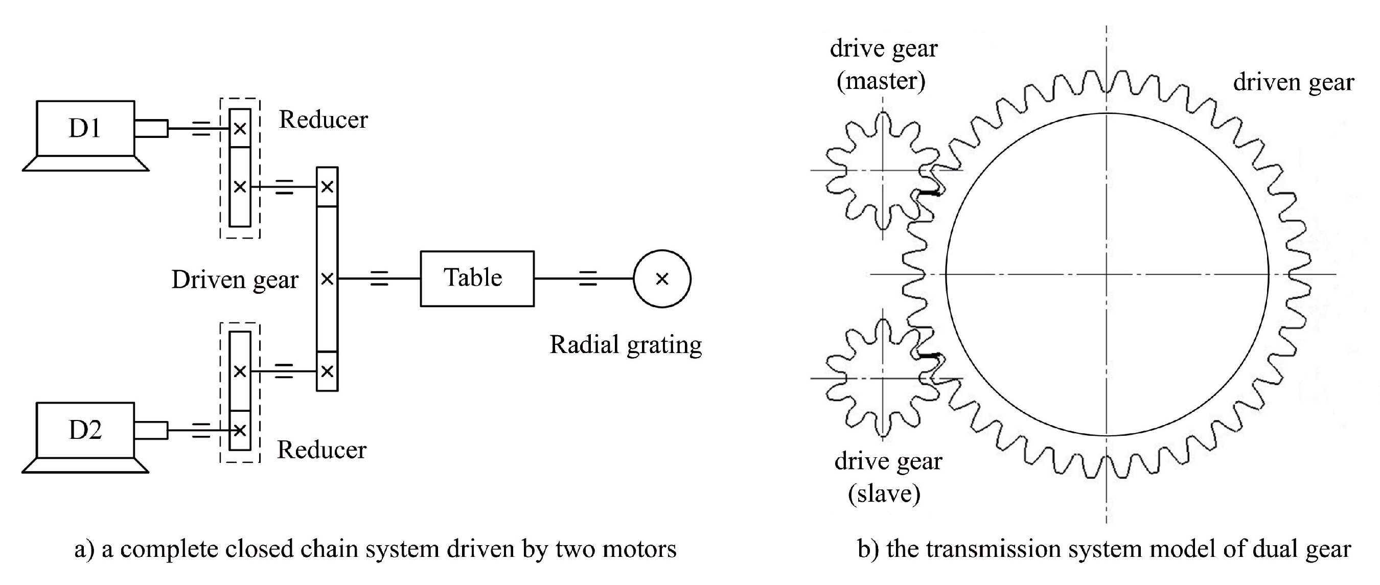
The master-slave control technology with dual servo motor can solve the above problems well. The dual servo motors D1 and D2 drive their independent transmission chains, respectively (as shown in
Figure 1), and engage with the large tooth ring of the work platform to form a complete closed-loop chain system. At the same time, the closed-loop feedback is carried out by the circular grating installed at the center of the main axis of the workbench, which can effectively improve the tracking characteristics and positioning accuracy of the C-axis system.
The C-axis of the super-heavy CNC vertical milling lathe uses the same type of two motors in order ensure the C-axis forward and backward torque is equal. Through the master-slave function of the CNC system, the C-axis gear ring is always subjected to an inverse torque. The end gears of the two independent transmission chains of the servo motor D1 and D2 are always engaged in both positive and negative direction with the corresponding meshing teeth of the large gear ring. This control mode restricts the positive and negative direction of the large gear ring and eliminates the gear transmission backlash of the large gear ring at the end of the C-axis, so as to improve the positioning accuracy.
In a dual servo motor system, D1 is the active drive motor and D2 is the driven drive motor. The servo motor D1 moves according to the motion parameters that are set by the numerical control system program. According to the instructions given by the numerical control system, the position ring and speed ring of the servo motor D1 are controlled. Servo motor D2, according to the numerical control system, has the function of master-slave control lag time t. According to the feed torque ratio of the servo motor D1, the motor D2 follows the driven motion. The input speed and position instruction of the servo motor D1 are taken as the input instruction of the servo motor D2. The servo motor D1 of the active driving table is driven in the closed-loop working chain, and the driven servo motor D2 works in the open-loop state. The drive control that is received by D2 is the speed and position signal of the active servo motor D1, so as to improve the synchronization control accuracy and stability of the C-axis closed-loop system.
From the principle of master-slave control, the clearance elimination process is realized in the feed phase. When the dual servo motor is in the acceleration and deceleration stages, the main drive motor D1 moves according to the specified signal, while the driven motor D2 always follows the active motor. When the main drive servo motor D1 acceleration process finished, driven motor D2 to follow the initiative and lag
t time to feed.
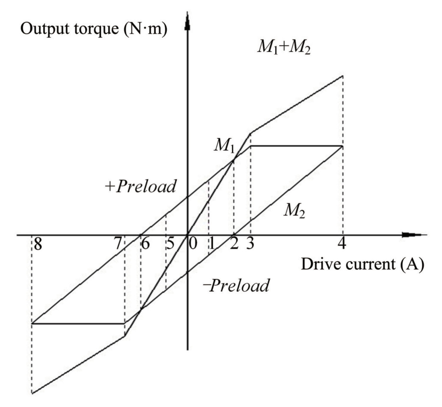
Figure 2 shows the driving torque relation of the double motor.
According to
Figure 2, when the C-axis accelerates clockwise at 0, the output torque of D1 and D2 of the dual servo motor driving the C-axis is equal and opposite, so that the two gears can engage with the opposite tooth surface of the big gear, respectively, and the errors caused by the gap between the teeth can be eliminated.
In the acceleration stage of 0-1-2, the active torque M1 gradually increases, while the driven torque M2 is in the opposite direction and it gradually decreases to zero. At the stage of 2, the output torque value of the driven motor is zero. The big gear rotates under the action of the pinion that is driven by the active motor, and the corresponding pinion rotates with the big gear.
In phase 2 to 3, the output torque of the servo motor D1 (active control motor) continues to increase, and the gears in the drive chain of the servo motor D2 engage in reverse, driving the C-axis rotation together with the servo motor D1. In the process of stage 3 to 4, the output torque of the servo motor D1 remains unchanged. The torque of the servo motor D2 gradually increases, and the C-axis works smoothly under the joint drive of the dual servo motor D1 and D2. In the process of C-axis acceleration driven by double servo motor, the large gear ring of the working platform is always driven by the common torque of D1 and D2 of the double servo machine, which restricts the gear ring to swing back and forth in the tooth side clearance, realizing the requirement of eliminating the tooth side clearance and improving the positioning accuracy of the machine tool.
When C-axis servo feed is reversed, the rotation direction of the servo motor D1 is unchanged, and the torque of the servo motor D1 and D2 gradually decreases in the stage of 4 to 2. The torque of the servo motor D1 (main drive motor) is greater than the torque of the servo motor D2 (driven motor), and the torque M1 is greater than or equal to the torque M2. In the stage of 2 to 0, the servo motor D2 torque commutation and gradually increase, the servo motor D2 transmission chain gear mesh commutation, tooth meshing opposite.
When the servo motor reaches 0 in the figure, D1 and D2 return to the accelerated state, and the C-axis stops. In the stages of 0 to 5, 5 to 6, 6 to 7, 7 to 8, the running state of the C-axis servo feed is consistent with the above accelerating state. At this time, the servo motor D1 is the driven motor, and the servo motor D2 is the active control drive motor.
3. Dynamics Modeling and Parameter Optimization of Double Motors Driving System
3.1. Dynamics Modeling of Dual Drive Motors with Gear Clearance
On the basis of the working principle of the servo drive motor, the equation of voltage balance in the armature circuit of the
n (
n = 1, 2) servo motor is derived without considering the influence of the clearance of the tooth side, as shown in Equation (
1).
where
is the inverse potential coefficient of the
nth motor,
is the motor angle (rad),
is the current in the motor’s armature circuit (A),
is the resistance of the armature circuit (
),
is the inductance of an armature circuit (H), and
is the armature voltage of an armature circuit (V).
The electromagnetic torque equation of the dual drive servo motor is Equation (
2).
where
is the torque coefficient of the motor and
is the torque of motor (Nm).
The torque balance equation of the double-drive servo motor is shown in Equation (
3).
where
is the rotational inertia of the motor (kg m
2),
is the equivalent viscous friction coefficient of the motor,
is the elastic torque between gear and motor shaft (Nm), and
i is the ratio between the gear and motor shaft.
The relation between the torsional angle of motor shaft and the torsional angle of the
nth gear can be expressed by Equation (
4).
The stress state of the driving gear is analyzed and its dynamic Equation (
5) is obtained.
where
is the rotational inertia of the driving gear (kg m
2),
is the equivalent viscous friction coefficient of the driving gear, and
is the elastic torque between the driving gear and the large gear (Nm).
Ignoring the influence of the coefficient of viscous friction, Equation (
6) is obtained between the large gear and the
nth driving gear according to the meshing principle.
where
and
are the elastic coefficient and the transmission ratio between the
nth driving gear and the large gear. Through the stress analysis of the large gear, the corresponding dynamic equation is obtained, as shown in Equations (7) and (8).
where
is the elastic torque of the large gear (Nm),
is the coefficient of viscous friction of the large gear,
is the torque driven by gear 1 (Nm), and
is the torque driven by gear 2 (Nm).
Equation (
2), Equation (
4), Equation (
5) and Equation (
6) are substituted into Equation (
3) to obtain the dynamic equation of the motor driven control system.
Multiply both sides of Equation (
9) by the transmission ratio to obtain Equation (
10).
Equation (
10) is simplified to Equation (
11).
where
=
+
,
=
+
,
=
i.
Substitute Equation (
4) into Equation (
1), and the armature circuit equation is transformed into Equations (12) and (13).
where
S =
i. According to Equation (
13), Equation (
11), Equation (
6), Equation (
7), and Equation (
8), the dynamic model can be obtained as Equation (
14).
Now consider the effect of gear clearance on the dynamic model. The clearance between drive gear and C-axis large gear can be expressed as
(
t), and the difference between the two objects position can be expressed as
(
t). Subsequently, the gear clearance model can be expressed as Equation (
15).
The non-linear functional expression describing the clearance between large gear and driving gear can be obtained from Equation (
15), as shown in Equation (
16).
When considering the influence of tooth gap, Equation (
16) is substituted into Equation (
14) in order to obtain the dynamic model of double motor drive with tooth side clearance, as follows.
where
,
.
,
,
,
are non-linear parameters of backlash. The specific expressions are shown in Equations (18)–(21).
By substituting Equations (18)–(21) into Equation (
17), the following can be obtained.
where
.
In summary, the equation of state of the dynamic model of double motor drive with tooth side clearance can be obtained, as shown in Equation (
23).
where
3.2. Dynamics Simulation of Dual Drive Motors with Gear Clearance
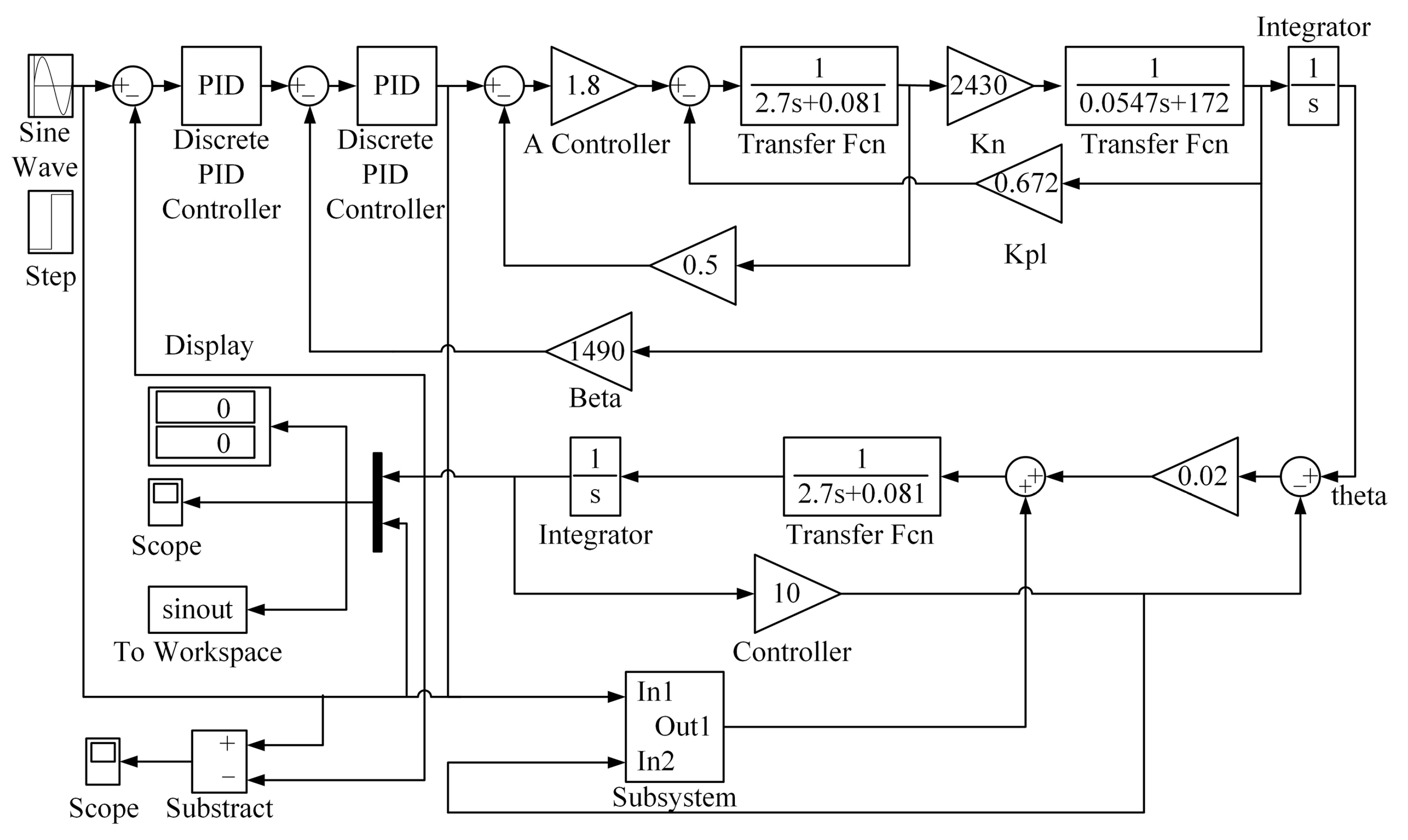
This section will analyze the influence of gear gap on C-axis drive system of super-heavy vertical milling lathe based on the established double-motor dynamics model. A backlash module was added between the corresponding two drive gears and large gear in Matlab Simulink to study the actual situation of dual motor drive under the influence of backlash. The control block diagram is shown in
Figure 3.
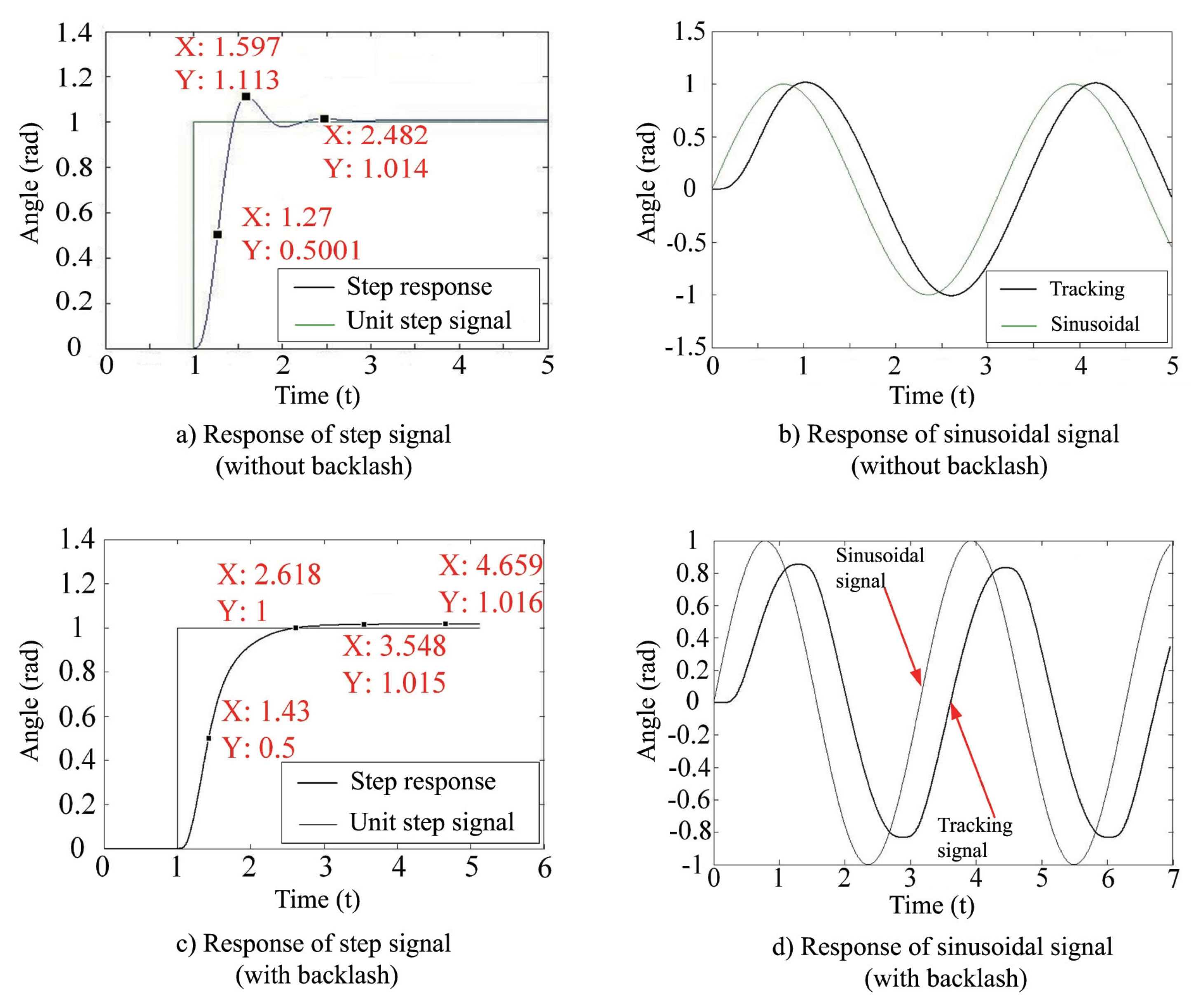
Figure 4 shows the response curve of the system under the input of unit step signal and sinusoidal signal when the PID parameter of the system is not adjusted. The output response of the normal unit step signal (
Figure 4a) is compared with that of the unit step signal obtained under the condition of backlash (
Figure 4c). It is found that the introduction of the non-linear link of the gear gap reduces the overruns of the dual motor master-slave control system, but also increases the response time of the system. In addition, the increase of the backlash parameter will lead to the instability of the control system and cause continuous oscillation. Under the condition that the integral time constant remains unchanged, the oscillation frequency of the step response of the system increases with the increase of the proportionality coefficient
K, and the oscillation amplitude increases gradually. If the proportionality coefficient
K is too small, then the oscillation frequency of the system is very low, but the adjustment time is too long, which cannot meet the actual demand of the high followability of the C-axis control system. While the proportion coefficient
K is set too large, the system has a short adjustment time, but the overshoot and oscillation amplitude are large, the oscillation frequency is high, and the control is unstable. By comparing the response results of the sinusoidal signals in
Figure 4b,d, it can be seen that the presence of the non-linear link of the backlash prolongs the response time of the system, reduces the amplitude, and reduces the followability of the C-axis control.
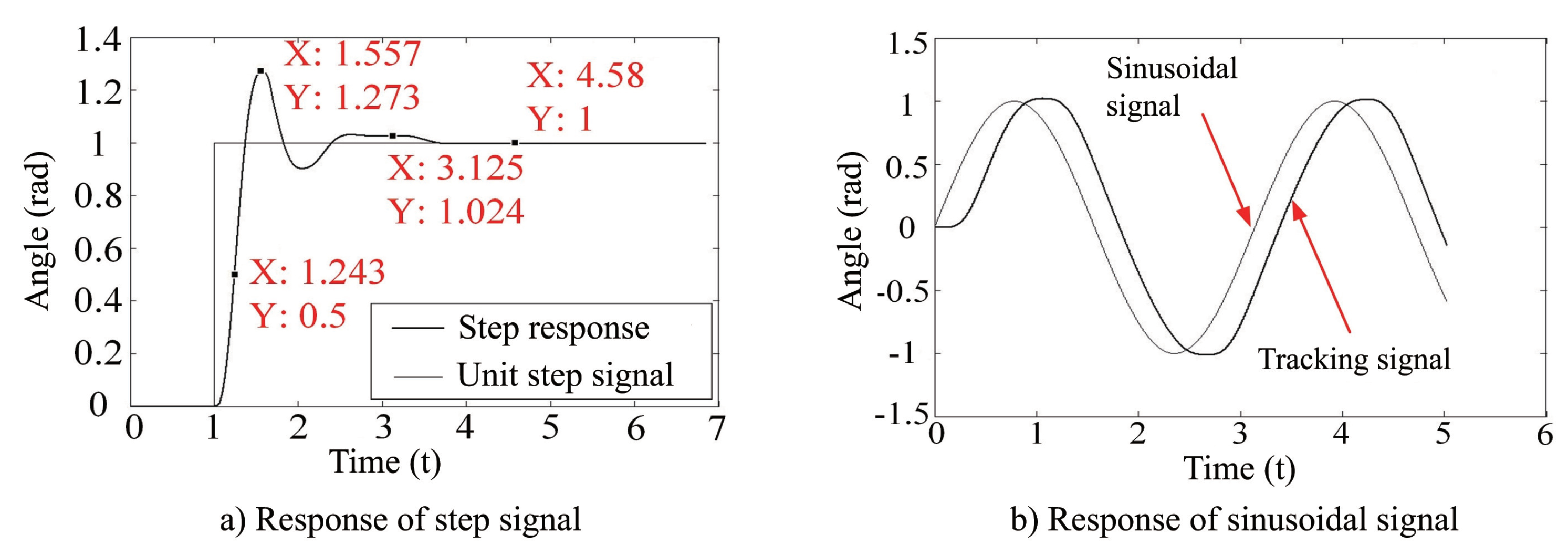
After PID parameter tuning, the response of the system to unit step signal and unit sinusoidal signal is shown in
Figure 5a,b. It can be seen that, after parameter setting, the dual motor drive control system can get better time domain control index. As can be seen from
Figure 5a, after tuning PID parameters, the signal’s rising time
= 1.557 s, delay time
= 1.243 s, adjustment time
= 3.1 s, overshooting quantity
p = 17%, and the number of oscillations
N = 2.
3.3. Parameter Optimization of Double Motors Drive System
The super-heavy vertical milling lathe studied in this paper uses the master-slave control function of Siemens 840D (Munich, Germany) numerical control system to realize the clearance compensation. The master-slave relationship of the motor is established in the numerical control system. The master-slave control adopts two torque controllers to provide offset torque for the drive shaft and driven shaft, respectively. Superposition the feedback speed and the tension torque setting (system parameters: MD37264). The result data are passed to the master slave axis to ensure that the driven axis is consistent with the speed of the drive axis when the drive axis gets the speed instruction.
The specific parameter setting and optimization steps of the function of eliminating mechanical clearance of master-slave dual drive are described, as follows.
(1) Checking the parameter setting of the machine tool. In addition to the parameters that are related to master-slave control, the parameters of the drive axis and the driven axis are guaranteed to be consistent (including the parameters of the second order filter).
(2) Optimizing the setting parameters of spindle current ring and speed ring, and set the same amplitude to drive shaft and driven shaft. The second order filter is added by adjusting the speed loop gain parameter and the spindle frequency response curve is adjusted to the best state.
(3) When the current loop and the velocity loop are optimized, the response curves on the spectrum should basically coincide. If the difference is large, the mechanical fault should be investigated before the master-slave optimization.
(4) The gain of the position loop is increased to the critical point of vibration under the condition that the dual-drive system runs smoothly and does not vibrate.
(5) Check the transmission clearance between the feed box gear and the rack of the worktable. Appropriately increase the oil film thickness of the hydrostatic guide in order to reduce the friction of the worktable. Eliminate the mechanical hidden trouble that is caused by the shaking of the worktable in the closed-loop debugging. Adjust position loop gain , = ···. The measured data show that the reduction of position loop gain enhances the stability of the system, so is set to 10.
(6) In the optimization process, the parameters of feedforward coefficient, feedforward equivalent time, DSC (dynamic rigid response), acceleration, JERK (added acceleration), and SOFT (axial impact limit) should be consistent.
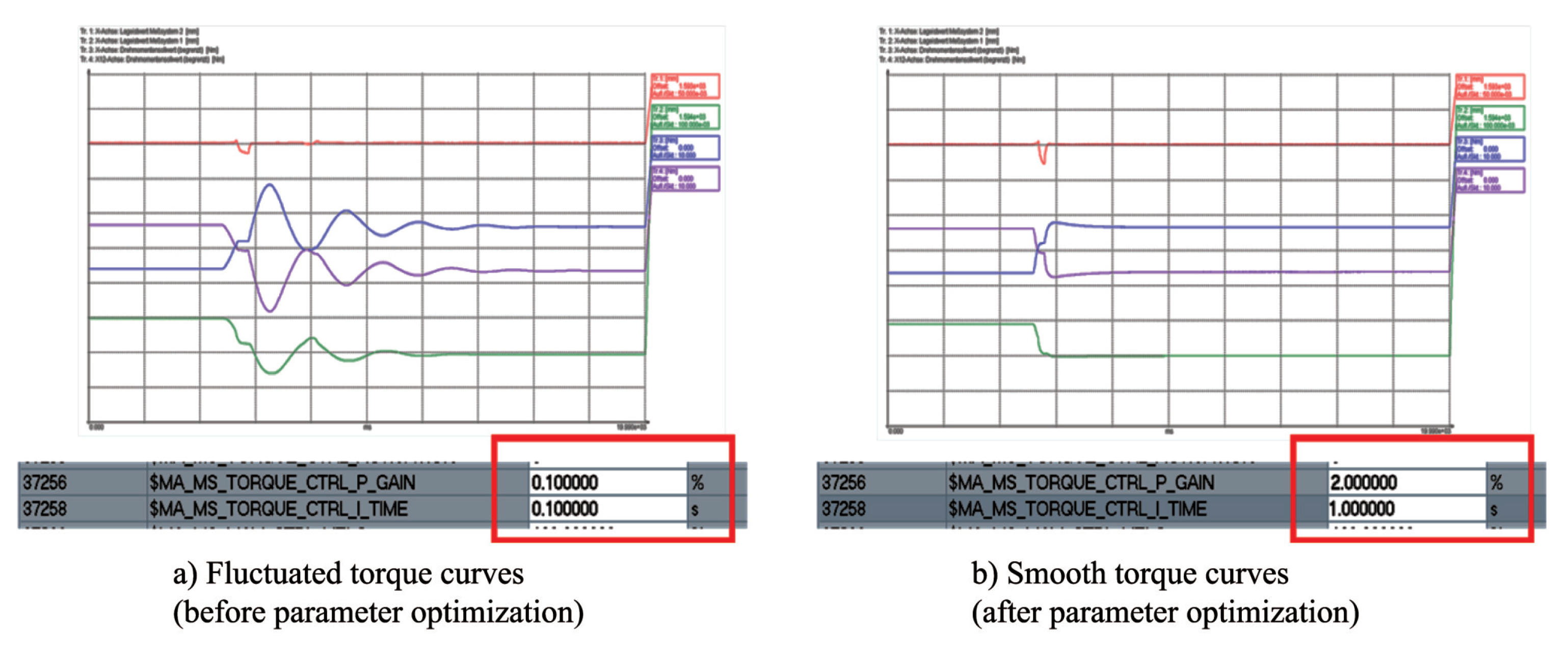
(7) In the process of tension force adjustment, the IBN Tool can be used to monitor the torque setting value of the drive axis and the driven axis. When adjusting torque parameters, the gain coefficient of the torque balance controller, namely the tension force (MD37256), should be set to 0 and activated. Subsequently, change the settings of MD37256 and MD37258 (integration time of torque balance controller), and check the trace results, as shown in
Figure 6.
The purple curve is the torque curve of the driving axis and the green curve is the torque curve of the driven axis, as can be seen from
Figure 6a. The fluctuation of the curve is the vibration frequency of the C-axis. In order to improve the accuracy of the C-axis and eliminate the gap between the gears, the curve needs to be adjusted until it is smooth, as shown in
Figure 6b.
(8) Trace tool is used to monitor the positioning of master and slave axes and adjust the parameters of acceleration, Jerk, and feedforward.
The above are the optimal parameters after the adjustment of the machine tool. By following the torque curve of the master-slave motor through the master-slave axis optimization method, the torque balance is achieved and the curve is smooth, so as to improve the precision of the double-drive C-axis.
4. Verification of Clearance Elimination of Double Motors
For super-heavy vertical milling lathe to have high milling and boring machining accuracy, the rotation Angle positioning error of the C axis of the worktable must be less than
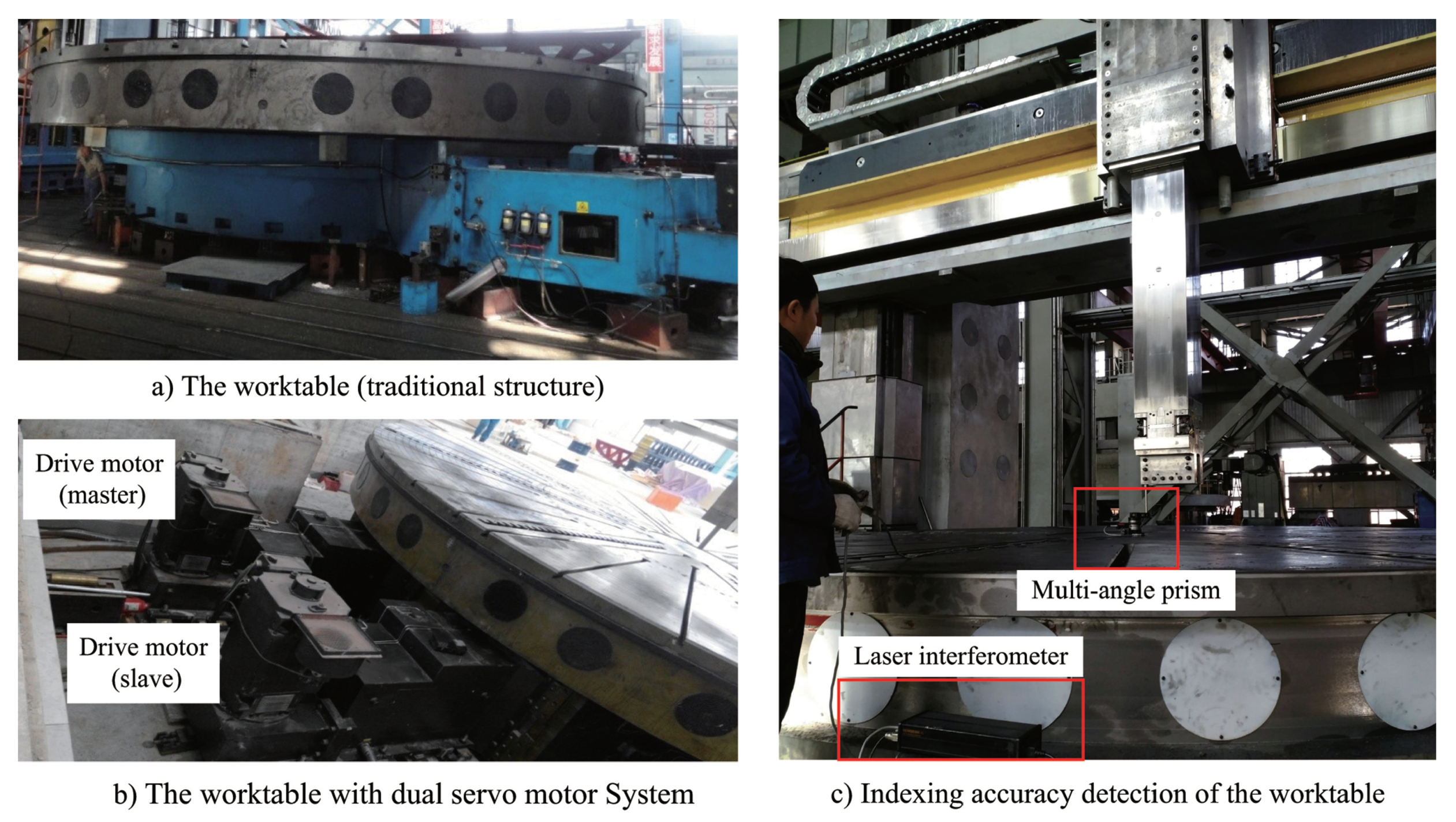
. The traditional gap elimination structure is to install an axially movable wheel group on a shaft of the transmission chain and realize the gap elimination through displacement. This experiment compares the effect of double-servo motor driven clearance worktable (as shown in
Figure 7b) with that of traditional clearance worktable of the same specification (as shown in
Figure 7a).
For the main transmission of two kinds of clearance elimination structures, the indexing accuracy of C-axis transmission of the worktable was monitored and the data were recorded under no-load condition. The measuring instrument is laser interferometer (with multi-angle prism).
Table 1 shows the experimental results of the comparison between the traditional C-axis structure and the presented double-servo motor structure in no-load working condition.
In the test of measuring the dividing precision of C-axis under no-load condition (as shown in
Figure 7c), the precision of the main driving table with double-servo drive structure is higher than that of the traditional structure.
According to the workpiece with different load weight, use the C-axis interpolation function to bore two holes with the diameter of 100 mm on the workpiece, verify the positioning accuracy of boring division and record the data. The measuring instrument is laser interferometer (with multi-resolution prism). When the workpiece is loaded with different weight, the comparative experiment of dividing precision of turning table is carried out. The experimental results are shown in
Table 2.
It can be seen from
Table 2 that the hole indexing accuracy of the workpiece processed by the traditional structural worktable C-axis at full load is 10
, which has reached the maximum tolerance. The precision of the boring division of workpiece processed by double servo control worktable C-axis meets the requirement of precision index of machine tool, and the precision is obviously higher than that of traditional main drive structure. The experiment proves that the clearance elimination structure by double servo motor presented in this paper is suitable for the application of super heavy-duty vertical milling lathe.


