Article

Effect of Heat Input on Formability, Microstructure, and Properties of Al–7Si–0.6Mg Alloys Deposited by CMT-WAAM Process

1
School of Metallurgy, Northeastern University, Liaoning 110006, China
2
Research Lab of WAAM Process, Inner Mongolia Metal Material Research Institute, Ningbo 315100, China
3
Technology Department, North East Industrial Materials & Metallurgy Co., Ltd., Fushun 113200, China
*
Author to whom correspondence should be addressed.
Appl. Sci. 2020, 10(1), 70; https://doi.org/10.3390/app10010070
Submission received: 29 November 2019 / Revised: 13 December 2019 / Accepted: 18 December 2019 / Published: 20 December 2019
(This article belongs to the Special Issue Additive Manufacturing in Industry)

Abstract

:

Featured Application

The effect of heat input on the formability, microstructure and properties of Al-7Si-0.6Mg alloys fabricated by wire arc additive manufacturing (WAAM) was investigated in this paper. The results can provide theoretical and data support for the engineering application of WAAM Al-7Si-0.6Mg.

Abstract

In order to improve the forming efficiency of Al–7Si–0.6Mg fabricated by wire and arc additive manufacturing process (WAAM), wire with a diameter of 1.6 mm was selected as the raw material. The effect of heat input on the formability, microstructure, and properties of the WAAM alloy was investigated, and the forming model was established. The WAAM alloys were characterized by electronic universal testing, scanning electron microscopy, energy spectrum analysis, and metallographic microscopy. The results show that Al–7Si–0.6Mg alloy has a large processing window under the cold metal transfer (CMT) process, and it can be well formed with a large range of heat input. The secondary dendrite arm spacing and Fe-phase in the as-deposited alloy gradually increase with an increase in heat input, and slight overburning occurs in the heat affected zone at higher heat inputs. After solid solution and aging treatment (T6 heat treatment), the size of α-Al grain and eutectic silicon grain increases with the increase of heat input. Little anisotropy in the mechanical properties is observed except at higher heat inputs. The tensile strength is 354.5 MPa ± 7.5 MPa, yield strength is 310 MPa ± 5.5 MPa, and elongation is 6.3 ± 0.7%.

1. Introduction

Wire arc additive manufacturing (WAAM), which is suitable for the integrated forming of large, medium, and complex parts [1], is a technology that melts metal wires and accumulates solid parts layer by layer under the action of arc. Compared with the high-energy beam and powder additive manufacturing [2,3], WAAM has a high forming efficiency, a high density of stacking body; compared with traditional forming methods (casting or forging) [4,5], WAAM has the characteristics of Buy-to-Fly ratio, excellent mechanical properties and short processing cycle. The cold metal transfer (CMT) technology has a high cladding efficiency, a low heat input, and no spatter [6,7]. Its application in the wire arc additive manufacturing (WAAM) of aluminum alloy has attracted considerable attention [7,8,9,10,11]. Ryan et al. [12] investigated the influence of the raw material batch and process parameters on the porosity of 2219 alloy by CMT-WAAM. Cong et al. [13,14] compared the microstructure and properties of the thin wall and block structures of Al–6.3%Cu alloy and investigated the effect of parameters on porosity of Al–6.3%Cu alloy deposited by CMT-WAAM. Gu et al. [15] investigated interlayer rolling on the properties and porosity of Al–4.5Mg alloy manufactured by CMT-WAAM process.
Al–7Si–0.6Mg alloys are widely used in automotive and aerospace [16,17,18] industries due to excellent castability and processability resistance. In particular, Al–7Si–0.6Mg alloys can have good mechanical properties after heat treatment. Li et al. [19] found that Al–7Si–0.6Mg alloy has good flow performance and molding performance in CMT-WAAM process. The structural products of the alloy prepared by WAAM technology have achieved engineering applications [20]. At present, the diameter of the materials used in the CMT-WAAM process is generally 1.2 mm [21,22,23]. Because of the limitation of the power supply process for CMT, the maximum wire feeding speed (WFS) is 9 m/min, that is, the maximum forming efficiency is 1.6 kg/h. In this paper, Al–7Si–0.6Mg aluminum alloy welding wire with a diameter of 1.6 mm was selected as raw material, and manufactured as-deposited alloy by CMT-WAAM process. The influence of heat input on the formability, microstructure, and properties of WAAM Al–7Si–0.6Mg alloy under the process condition of WFS > 5 m/min (that is, forming efficiency > 1.6 kg/h) were investigated in detail. The aim is to provide theoretical and data support for the Al–7Si–0.6Mg alloys deposited by WAAM further engineering applications.

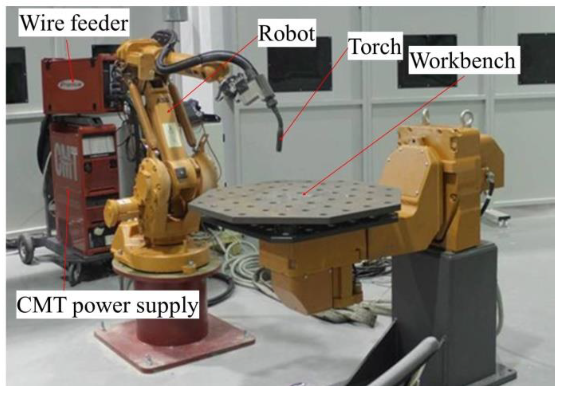
2. Materials and Methods

The ER4220 aluminum alloy welding wire with a diameter of 1.6 mm manufactured by North East Industrial Materials & Metallurgy Co., Ltd. (NEIMM, Fushun, China) was selected as the raw material, and the substrate was 6061-O aluminum alloy plate with the dimensions of 300 mm × 150 mm × 10 mm. The chemical compositions of the raw material and substrate are listed in Table 1. The WAAM system shown in Figure 1 was built by CMT advanced 4000 R power supply of Fronius Company and ABB 1410 robot. The WAAM alloys were prepared by the single layer and multichannel forming path. Figure 2 shows the forming process. The length and height of the WAAM alloy were 200 mm and 140–150 mm. During the WAAM process, the interlayer temperature was maintained in the range of 160–180 °C, and the shielding gas flow at 25 L/min. The process parameters of the additive process are listed in Table 2. The equation H i = η ( U ¯   I ¯ ) / T S is used to calculate the heat input of each group of experiments, where HI (J/mm) is the heat input of the welding process, U ¯ ( V ) is the average value of each stack voltage, I ¯ ( A ) is the average value of each stack current, η is the thermal efficiency of CMT process set to 0.8 [24], and TS (mm/s) is the welding speed (WS).
The as-deposition alloys were treated via T6 heat treatment (540 °C, 12 h, 175 °C, and 4 h). Three parallel tensile samples and the metallographic sample were intercepted from the WAAM alloy using water jet, band saw, wire cutting, milling machine, grinder, and other tools. The sampling position is presented in Figure 3 and the dimensions of the tensile sample are presented in Figure 4. The thickness and total height of the WAAM alloy was measured using a Vernier caliper with an accuracy of 0.02 mm; the chemical compositions of the raw materials, substrates, and WAAM alloy were analyzed via direct reading spectrometer (FOUNDRY-MASTER Xpert, GER). A universal testing machine (WDW-30, CHN) was used to test the tensile properties of the sample, and a scanning electron microscope (SEM, Quanta FEG 250, USA) was used to observe its microstructure and for the energy spectrum analysis (EDS, USA) of the phase. The metallographic samples were etched with Kroll’s reagent (2 mL HF, 6 mL HNO3, 92 mL H2O), and the microstructure was observed under a metallographic microscope (OM, Axio Imager A2m, GER).

3. Results

3.1. Burning Loss of Elements

The fluctuations in the chemical composition of the WAAM alloy are shown in Figure 5. As the heat input increased, the burning loss of Si and Mg gradually increased. The burning loss of Si increased from 1% (1#) to 3.5% (17#) and that of Mg increased from 3.5% (1#) to 11.3% (17#). However, the contents of Ti and Fe in the WAAM alloy did not change significantly. The range of the contents of Si, Mg, Ti, and Fe in the WAAM alloy was still within the standard (ISO3522) requirements of the Al–7Si–0.6Mg alloy.

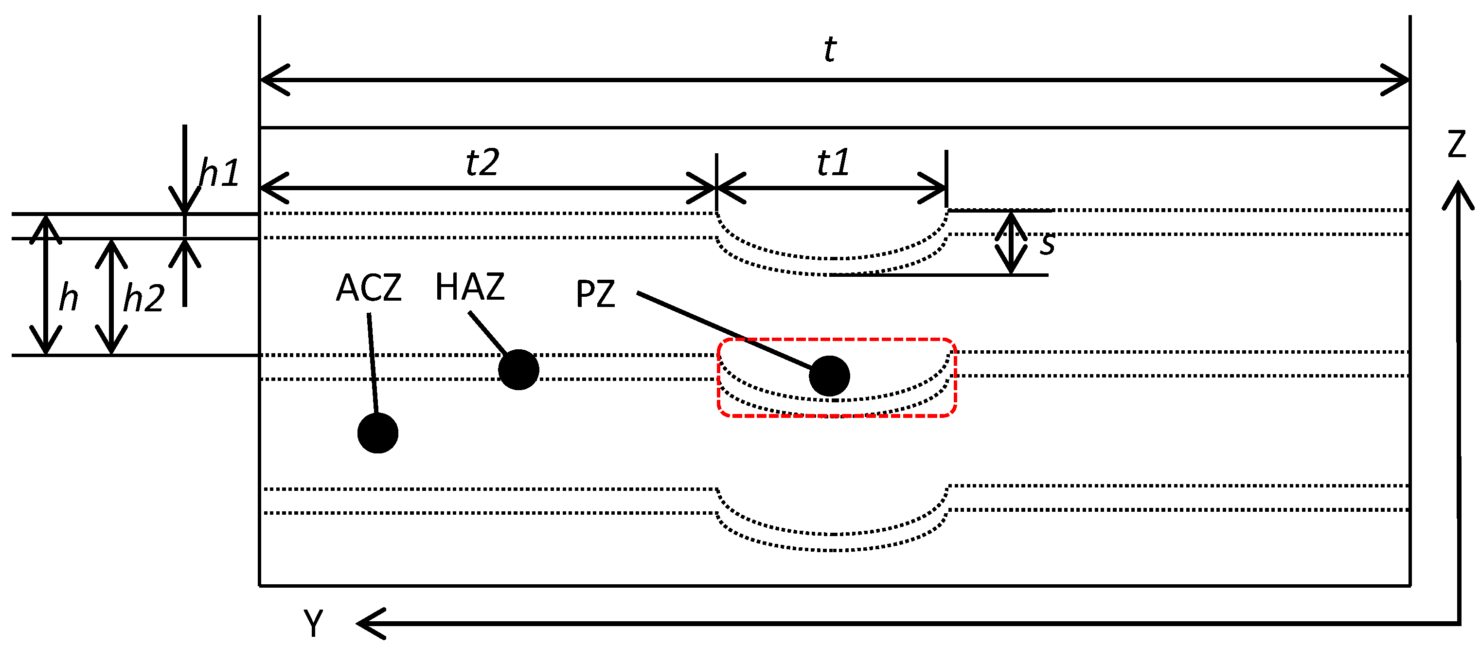
3.2. Effect of Heat Input on Forming

The cross section of the WAAM alloy is shown in Figure 6. For the heat input range of 73.13–470.95 J/mm, it is evident that the alloys can be well formed, with the exception of the 15# alloy. As the WFS of 15# was up to 6.5 m/min, and the current is large, which increases welding penetration, the arc impacted and violently stirred the molten pool, thereby damaging the gas protection. This resulted in the failure of forming, as shown in Figure 6 (15#).
The average layer height was calculated by the formula:
average   layer   height   =   total   height   of   WAAM   alloy number   of   layers
The thickness measurement results and average layer height of the WAAM alloys are shown in Figure 7. With an increase in the heat input, the thickness and average layer height of the WAAM alloy increased gradually, the thickness increased from 8.1 mm to 18.4 mm, and average layer height increased from 0.45 mm to 1.20 mm. During the WAAM process, a decrease in the WS increased the heat per unit volume. Hence, the aluminum alloy wire flowed to both sides after melting, thereby increasing the thickness of the deposit. The layer height was mainly affected by the WFS and the WS. Furthermore, an increase in the WFS and a decrease in the WS led to an increase in the layer height.

3.3. Microstructure and Properties

3.3.1. Macrostructure

The macrostructure of the WAAM alloy is shown in Figure 8, which can be divided into three areas: penetration zone (PZ) affected by arc, heat affected zone (HAZ), and as cast zone (ACZ) as show in Figure 8A–C, respectively. Moreover, the macrostructure model of the WAAM alloy was established, as shown in Figure 9, where t1 is the width of the PZ; t2 is the width of deposit spreading zone; t is the effective thickness of the WAAM alloy (=t1 + 2t2); s is the depth of the single layer in the PZ; h1 is the height of the HAZ; h2 is the height of the ACZ; h is the height of the single layer (=h1 + h2). According to the research results of Gu [25], h and t increase with WFS and decrease with increasing WS. The window of WFS studied in this paper was smaller (5.0–6.0 m/min); thus, the main factor influencing h and t was WS. With the decrease in WS, h and t gradually increased, as shown in Figure 7. h consists of two parts: height of the HAZ (h1) and height of the ACZ (h2). h1 is affected by heat input (i.e., with the increase in heat input, h1 will gradually increase). Moreover, t is composed of two parts: width of the PZ (t1) and width of deposit spreading zone (t2). t1 is affected by the WFS (the CMT power automatically equates to the current and voltage according to the WFS, while the width of the PZ is mainly affected by the voltage). In addition, t2 plays an important role in that t is affected by heat input (i.e., with the increase in heat input, t2 will increase gradually). The depth of the PZ (s) is mainly affected by the WFS (current). With the increase in WFS, s will increase gradually.

3.3.2. Microstructure

The 1#, 10#, 17# samples were selected from the as-deposition WAAM alloys. The micro porosity (Figure 10), microstructure (Figure 11), the Fe-rich phase (Figure 12), and microstructure after T6 heat treatment (Figure 13) of the WAAM alloys were observed. It can be seen that there were mainly spherical porosity defects in the as-deposited WAAM alloy. The pore size was mainly tens of microns, and the distribution was random. The size and number of pores did not change significantly with the increase of heat input. Furthermore, the micropores in the WAAM alloy have no effect on the ultimate tensile strength and yield strength [19].
The microstructure of the as-deposition WAAM alloy is shown in Figure 11. It can be seen that the WAAM alloy can be clearly divided into the PZ, HAZ and ACZ. It should be noted that the observed height of the HAZ (h1) did not increase with heat input, due to the fluctuation of the arc caused by environmental interference (such as air flow and magnetic bias blowing) and the uncontrolled flow of the liquid alloy during WAAM processing, resulting in the mutual mixing between adjacent layers. Nevertheless, the hierarchical structure can be clearly observed. The HAZ of the as-deposition WAAM alloy is shown in Figure 11d–f. Compared with the ACZ, the eutectic silicon structure was obviously spheroidized, and the structural morphology of the HAZ was similar under the condition of low heat input, such as that observed in Figure 11d,e. However, under the condition of high heat input (Figure 11f), the heat affected zone showed slight overburning, as shown in Figure 11f. The ACZ of the as-deposition WAAM alloy is shown in Figure 11g–i. It can be seen that with heat input increasing, the α-Al dendrites in the ACZ became coarser, the number of dendrites decreased, and the secondary dendrite arm spacing (SDAS) increased gradually. After amplifying the ACZ, the fine-needle-like or short-bar-like Fe-phase was observed. The EDS analysis results are shown in Figure 12. It is known that the observed phase is the π-Fe phase (Al8Mg3FeSi6) [26], and its size gradually increases with heat input. This is because the Al–7Si–0.6Mg alloy is a hypoeutectic alloy. α-Al precipitates first in the solidification process. With the decrease in temperature, eutectic silicon and the second phase particles (Fe phase) form between α-Al dendrites. Under the condition of high heat input, the solidification process of the alloy becomes relatively slow, resulting in sufficient time for silicon and Fe phases in the eutectic region to aggregate and grow. Therefore, the SDAS of the as-deposition WAAM alloy increases gradually, and the Fe phase transforms and coarsens with the increase in heat input.
The microstructure of the WAAM alloy after T6 heat treatment is shown in Figure 13. There were mainly α-Al, Si particles and Fe-rich phases in the WAAM alloy (T6); the EDS analysis results are shown in Figure 14. It can be seen that the sizes of the α-Al and the eutectic silicon grains in the alloy tended to increase with the increase in heat input. The size increment is attributed to the small SDAS of the alloy at low heat input: the shorter the average free path of diffusion and migration of the second phase particles, such as Mg2Si and Si, the easier the homogenization. With the increase in heat input, the SDAS of the WAAM alloy increased gradually, which impeded the fusion of the eutectic silicon particles in the solid solution, thus resulting in the increase in eutectic silicon particle size.

3.3.3. Mechanical Properties

Figure 15 shows the mechanical properties of the WAAM alloy (after T6 heat treatment). It can be seen that the ultimate tensile strength (UTS), yield strength (YS), and elongation of the alloy fluctuate in a small range within a large heat input range (1#–11#). Moreover, there is almost no difference between the horizontal (X-axis) and vertical (Z-axis) properties. The UTS was 354.5 MPa ± 7.5 MPa, YS was 310.5 ± 5.5 MPa, and elongation was 6.3 ± 0.7%. With the increase in heat input, the difference between the horizontal and vertical UTS of the WAAM alloy increased, the horizontal UTS was 15MPa higher than that of the vertical, the YS slightly decreased to 298 MPa ± 5 MPa, and the elongation gradually decreased from 5.95% (11#) to 4.15% (17#).
With the increase in heat input, the SDAS and size of the Fe-phase in the WAAM alloy increased gradually, and the α-Al and eutectic silicon grains in the WAAM alloy increased gradually after the heat treatment, thus, the elongation of the WAAM alloy decreased. On the other hand, due to the increase in heat input, slight overburning occurred in the HAZ of the WAAM alloy, which caused the decrease in the vertical properties.

4. Conclusions

(1) The Al–7Si–0.6Mg alloy can be well formed in the larger heat input range of CMT-WAAM. The chemical composition of the alloy after forming can meet the requirements of the relevant standards. The forming model of the WAAM Al–7Si–0.6Mg alloy with a raw material of φ1.6 mm is established.
(2) The microstructure of the WAAM Al–7Si–0.6Mg alloy has the characteristics of the DPZ, HAZ, and ACZ. With the increase in heat input, the SDAS of the as-deposition WAAM alloy increases and the Fe-phase coarsens gradually. Under the condition of high heat input, slight overburning occurs in the HAZ. After T6 heat treatment, the size of the α-Al and eutectic silicon grains in the alloy increases with the increase in heat input.
(3) The mechanical properties of the WAAM Al–7Si–0.6Mg alloy remain stable over a large range of heat input (1#–11#), and there is almost no difference in the horizontal and vertical properties. The UTS is 354.5 ± 7.5 MPa, the YS is 310 ± 5.5MPa, and the elongation is 6.3 ± 0.7%. However, with the increase in heat input, the horizontal and vertical UTS differences increase, the YS slightly decreases, and the elongation decreases from 5.95% (11#) to 4.15% (17#).
(4) The Al–7Si–0.6Mg alloy has a large processing window, good formability and mechanical properties under the WAAM process conditions. The selection of raw materials with the diameter of 1.6 mm can improve the forming efficiency, which will facilitate the engineering application of the WAAM process.

Author Contributions

C.L., H.G. and Y.Z. conceived and designed the experiments; C.L., S.W. and Z.W. performed the experiments; C.L., W.W. and L.R. analyzed the data; C.L., Z.M. and Y.Z. contributed reagents/materials/analysis tools; C.L. and H.G. wrote the paper. All authors have read and agreed to the published version of the manuscript.

Funding

This research received no external funding.

Acknowledgments

The authors thank North East Industrial Materials & Metallurgy Co., Ltd. (NEIMM) for providing ER4220 (φ1.6 mm) welding wires and Inner Mongolia Metal Material Research Institute for providing test support. The authors thank the financial support from National Key R&D Program of China (Item No: 2018YFB1106300-5).

Conflicts of Interest

The authors declare no conflict of interest.

References

  1. Martina, F.; Mehnen, J.; Williams, S.W.; Colegrove, P.; Wang, F. Investigation of the benefits of plasma deposition for the additive layer manufacture of Ti–6Al–4V. J. Mater. Process. Technol. 2012, 212, 1377–1386. [Google Scholar] [CrossRef] [Green Version]
  2. Rao, J.H.; Zhang, Y.; Fang, X.; Chen, Y.; Wu, X.; Davies, C.H.J. The origins for tensile properties of selective laser melted aluminium alloy A357. Addit. Manuf. 2017, 17, 113–122. [Google Scholar] [CrossRef]
  3. Brandl, E.; Heckenberger, U.; Holzinger, V.; Buchbinder, D. Additive manufactured AlSi10Mg samples using Selective Laser Melting (SLM): Microstructure, high cycle fatigue, and fracture behavior. Mater. Des. 2012, 34, 159–169. [Google Scholar] [CrossRef]
  4. Williams, S.W.; Martina, F.; Addison, A.C.; Ding, J.; Pardal, G.; Colegrove, P. Wire + arc Additive Manufacturing. Mater. Sci. Technol. 2016, 32, 641–647. [Google Scholar] [CrossRef] [Green Version]
  5. Ding, J.; Colegrove, P.; Mehnen, J.; Ganguly, S.; Almeida, P.M.S.; Wang, F.; Williams, S. Thermo-mechanical analysis of Wire and Arc Additive Layer Manufacturing process on large multi-layer parts. Comput. Mater. Sci. 2011, 50, 3315–3322. [Google Scholar] [CrossRef] [Green Version]
  6. Srikanth, T.; Surendran, S.; Balaganesan, G.; Manjunath, G.L. Response of CMT Welded Aluminum AA5086-H111 to AA6061-T6 Plate with AA4043 Filler for Ballistic. Procedia Eng. 2017, 194, 522–528. [Google Scholar] [CrossRef]
  7. Fang, X.; Zhang, L.; Li, H.; Li, C.; Huang, K.; Lu, B. Microstructure Evolution and Mechanical Behavior of 2219 Aluminum Alloys Additively Fabricated by the Cold Metal Transfer Process. Materials 2018, 11, 812. [Google Scholar] [CrossRef] [Green Version]
  8. Qi, Z.; Qi, B.; Cong, B.; Sun, H.; Zhao, G.; Ding, J. Microstructure and mechanical properties of wire + arc additively manufactured 2024 aluminum alloy components: As-deposited and post heat-treated. J. Manuf. Process. 2019, 40, 27–36. [Google Scholar] [CrossRef] [Green Version]
  9. Ortega, A.G.; Luis, C.G.; Mehdi, S.; Moussaoui, K.; Segonds, S.; Rouquette, S.; Deschaux-Beaume, F. Characterisation of 4043 aluminium alloy deposits obtained by wire and arc additive manufacturing using a Cold Metal Transfer process. Sci. Technol. Weld. Join. 2019, 24, 538–547. [Google Scholar] [CrossRef] [Green Version]
  10. Gu, J.; Bai, J.; Ding, J.; Williams, S.; Wang, L.; Liu, K. Design and cracking susceptibility of additively manufactured Al-Cu-Mg alloys with tandem wires and pulsed arc. J. Mater. Process. Technol. 2018, 262, 210–220. [Google Scholar] [CrossRef]
  11. Qi, Z.; Cong, B.; Qi, B.; Sun, H.; Zhao, G.; Ding, J. Microstructure and mechanical properties of double-wire + arc additively manufactured Al-Cu-Mg alloys. J. Mater. Process. Technol. 2018, 255, 347–353. [Google Scholar] [CrossRef]
  12. Ryan, E.M.; Sabin, T.J.; Watts, J.F.; Whiting, M.J. The influence of build parameters and wire batch on porosity of wire and arc additive manufactured aluminium alloy 2319. J. Mater. Process. Technol. 2018, 262, 577–584. [Google Scholar] [CrossRef]
  13. Cong, B.; Qi, Z.; Qi, B.; Sun, H.; Zhao, G.; Ding, J. A Comparative Study of Additively Manufactured Thin Wall and Block Structure with Al-6.3%Cu Alloy Using Cold Metal Transfer Process. Appl. Sci. 2017, 7, 275. [Google Scholar] [CrossRef]
  14. Cong, B.; Ding, J.; Williams, S. Effect of arc mode in cold metal transfer process on porosity of additively manufactured Al-6.3% Cu alloy. Int. J. Adv. Manuf. Technol. 2015, 76, 1593–1606. [Google Scholar] [CrossRef]
  15. Gu, J.; Wang, X.; Bai, J.; Ding, J.; Williams, S.; Zhai, Y.; Liu, K. Deformation microstructures and strengthening mechanisms for the wire+ arc additively manufactured Al-Mg4.5Mn alloy with inter-layer rolling. Mater. Sci. Eng. A 2018, 712, 292–301. [Google Scholar] [CrossRef]
  16. Wang, Q.G.; Davidson, C.J. Solidification and precipitation behaviour of Al-Si-Mg casting alloys. J. Mater. Sci. 2001, 36, 739–750. [Google Scholar] [CrossRef]
  17. Colombo, M.; Gariboldi, E.; Morri, A. Er addition to Al-Si-Mg-based casting alloy: Effects on microstructure, room and high temperature mechanical properties. J. Alloy. Compd. 2017, 708, 1234–1244. [Google Scholar] [CrossRef]
  18. Lin, Y.C.; Luo, S.C.; Huang, J.; Yin, L.X.; Jiang, X.Y. Effects of solution treatment on microstructures and micro-hardness of a Sr-modified Al-Si-Mg alloy. Mater. Sci. Eng. A 2018, 725, 530–540. [Google Scholar] [CrossRef]
  19. Li, C.; Gu, H.; Wang, W.; Zhai, Y.; Ming, Z.; Wang, S.; Ren, L.; Wang, Z. Investigation on microstructure and properties of aluminum alloy (ZL114A) by wire arc additive manufacturing (WAAM). Rare Met. Mater. Eng. 2019, 48, 2917–2922. [Google Scholar]
  20. Lu, J. “Ningbo Zhizao” helps satellite soar to the sky. Ningbo Daily, 7 October 2018; p. H5. [Google Scholar]
  21. Horgar, A.; Fostervoll, H.; Nyhus, B.; Ren, X.; Eriksson, M.; Akselsenab, O.M. Additive manufacturing using WAAM with AA5183 wire. J. Mater. Process. Technol. 2018, 259, 68–74. [Google Scholar] [CrossRef]
  22. Wang, S.; Gu, H.; Wang, W.; Li, C.; Ren, L.; Wang, Z.; Zhai, Y.; Ma, P. Microstructure and Mechanical Properties of aluminum alloy (ZL205A) wall produced by wire arc additive manufacturing method. Rare Metal. Mater. Eng. 2019, 48, 2910–2916. [Google Scholar]
  23. Gu, J.; Ding, J.; Williams, S.W.; Gu, H.; Bai, J.; Zhai, Y.; Ma, P. The strengthening effect of inter-layer cold working and post-deposition heat treatment on the additively manufactured Al–6.3Cu alloy. Mater. Sci. Eng. A 2016, 651, 18–26. [Google Scholar] [CrossRef] [Green Version]
  24. Pépe, N.; Egerland, S.; Colegrove, P.A.; Yapp, D.; Leonhartsberger, A.; Scotti, A. Measuring the process efficiency of controlled gas metal arc welding processes. Sci. Technol. Weld. J. 2011, 6, 412–417. [Google Scholar] [CrossRef] [Green Version]
  25. Gu, J. Study on Microstructure and Mechanical Properties of Additive Manufactured Al-Cu-(Mg) Alloys with the CMT Process. Ph.D. Thesis, Northeastern University, Shenyang, China, 2014; pp. 44–45. [Google Scholar]
  26. Li, C.; Gu, H.; Wang, W.; Wang, S.; Ren, L.; Zhai, Y.; Wang, Z.; Ming, Z. Effects of Fe Content on Microstructure and Properties of Al-7Si-0.6Mg alloy by Wire Arc Additive Manufacturing (WAAM). Rare Metal Mater. Eng. 2019. Accepted. [Google Scholar]
Figure 1. Wire arc additive manufacturing (WAAM) system.
Applsci 10 00070 g001
Figure 2. Schematic of WAAM process.
Applsci 10 00070 g002
Figure 3. Schematic diagram of sampling position.
Applsci 10 00070 g003
Figure 4. Tensile test sample drawing.
Applsci 10 00070 g004
Figure 5. Chemical composition of WAAM alloys.
Applsci 10 00070 g005
Figure 6. Cross section of WAAM alloy and top surface of 15# alloy.
Applsci 10 00070 g006
Figure 7. Thickness and layer height of WAAM alloy under different heat inputs.
Applsci 10 00070 g007
Figure 8. Macro metallographic pictures of WAAM alloy (A is penetration zone (PZ); B is heat affected zone (HAZ); C is as cast zone (ACZ)).
Applsci 10 00070 g008
Figure 9. WAAM alloy model.
Applsci 10 00070 g009
Figure 10. Porosity and distribution as-deposition WAAM alloy and SEM image of porosity.
Applsci 10 00070 g010
Figure 11. Microstructure of the as-deposition WAAM alloys. (ac) The microstructure near PZ of WAAM alloy of 1#, 10# and 17#; (df) the microstructure in HAZ of WAAM alloy of 1#, 10# and 17#; (gi) the microstructure in the ACZ of WAAM alloy of 1#, 10# and 17#; (jl) the microstructure amplification structure in the ACZ of WAAM alloy of 1#, 10# and 17#.
Applsci 10 00070 g011
Figure 12. SEM and EDS analysis results of the Fe-rich phase in the as-deposited WAAM alloy.
Applsci 10 00070 g012
Figure 13. Microstructure of the WAAM alloy after T6 heat treatment.
Applsci 10 00070 g013
Figure 14. SEM and EDS analysis results of the Si and Fe-rich phase in the WAAM alloy after T6 heat treatment.
Applsci 10 00070 g014
Figure 15. Mechanical properties of the T6-treated WAAM alloy.
Applsci 10 00070 g015
Table 1. Chemical composition of raw materials and substrates (wt %).
SiMgTiSrFe
ER42207.020.650.1100.0280.113
6061-O0.621.03————0.132
Table 2. Process parameters.
No.Wire Feeding Speed (m/min)Welding Speed (mm/s)Current I ¯ ( A ) Voltage U ¯ ( V ) HI (J/mm)
1#548.019522.573.13
3#5.535.921523.0110.19
4#635.923623.5123.59
6#5.524.321523.0162.80
7#5.519.821523.0199.80
8#619.823623.5224.08
9#515.619522.5225.00
10#5.515.621523.0253.59
11#615.623623.5284.41
12#510.419522.5337.50
13#5.510.421523.0380.38
14#58.219522.5428.05
15#6.524.325524.0-
17#5.58.421523.0470.95

