1. Introduction
Visual augmented reality (AR) technology aims to enhance the user’s view of the real world by overlaying computer generated elements on it. Currently, optical see-through (OST) head mounted displays (HMDs) are at the leading edge of the AR technology, and they have the potential to become ubiquitous eventually in different fields of applications [
1,
2,
3].
Nevertheless, their profitable usage across medical and industrial settings is still hampered by the complexity of the display calibration procedures required to ensure accurate spatial alignment between a real-world scene and computer generated elements [
4,
5]. The display calibration procedures of consumer level OST devices are rather simplified to improve usability, and this is achieved at the expense of sub-optimal results that are not tolerable for those applications for which the accurate alignment between virtual content and perceived reality is of the utmost importance [
6]. This aspect is pushing research towards the realization of standardized OST calibration procedures that are not only flexible and easy to replicate, but that can also provide reliable and accurate results.
Overall, in visual AR applications, the problem of defining the appropriate spatial location of the digital 3D content with respect to the real scene is the principal factor that provides the user with a sense of perceptual congruity [
7]. This problem is particularly challenging in OST HMDs, for the solution of which, knowing of the position of the user’s viewpoint(s) cannot be overlooked. On a first approximation, a single OST display can be modeled as an off-axis pinhole camera whose imaging plane corresponds to the semi-transparent virtual screen of the display and whose projection center corresponds to the nodal point of the user’s eye [
8].
The goal of the OST display calibration is therefore to estimate the projection parameters of the combined eye–display system that encapsulates the optical features of the display and whose values vary according to the position of the user’s eye with respect to the imaging plane of the display.
Manual calibration procedures rely on user interaction to collect sets of 3D-2D correspondences by aligning, from different viewpoints, world reference points to image points shown on the HMD virtual screen [
9]. These methods, particularly when aimed at estimating all the projection parameters simultaneously, are tedious, highly dependent on operator skill, time consuming, and should be repeated every time the HMD moves on the user’s head.
To lessen the burden on users in terms of time and workload, the calibration process can then be broken down into two phases: a first phase in which all the eye–display projection parameters are determined by performing a sort of factory calibration, ideally in a controlled setup; a second prior-to-use phase in which the calibration is refined by adjusting just a small subset of projection parameters. This is the underlying rationale behind several simplified manual calibration procedures, also referred to as semi-automatic calibration methods [
10].
Finally, interaction-free calibration methods that exploit eye tracking techniques are ideally the preferred option for those AR applications that demand for accurate virtual-to-real spatial alignment over an extended period of time [
8,
11]. Such is the case of OST HMDs used as an aid to high precision tasks (e.g., for surgical or industrial applications). However, and as we illustrate in more detail in the next section, none of these methods is thoroughly automatic, since they also rely upon an off-line calibration phase performed manually or through a calibrated camera that replaces the user’s eye in a controlled setup.
Therefore, irrespective of the approach chosen, the off-line calibration step is paramount to minimize the human element, and for this reason, it ought to be highly accurate and reliable.
This paper presents an approach for performing accurate off-line camera based calibrations of OST HMDs. In our procedure, the projection parameters of the eye–display model are estimated by means of standard camera calibration and computer vision techniques. To this aim, the OST HMD must be mounted over a rigid and adjustable holder equipped with a camera that replaces the user’s eye.
The main contributions of our work are as follows:
An off-line calibration procedure that is easy to replicate in both laboratory environments and real-world settings.
A calibration procedure that can work with any type of OST HMD: with finite and infinite focal distances, with complex or simple optical combiners, featuring inside-out or outside-in tracking mechanisms.
A calibration procedure that is completely automated.
A calibration procedure that entails a simple on-line refinement step to account for the user’s eye position.
A detailed formulation of all the mathematical steps involved in the procedure.
The remainder of this paper is structured as follows:
Section 2 surveys different two phase approaches for OST HMD calibration.
Section 3 provides a general overview of our camera based OST HMD calibration procedure together with its mathematical formulation starting from the standard projection matrix of the off-axis pinhole camera model of the eye–display.
Section 4 illustrates the technical implementation of the calibration procedure.
Section 5 describes the experiments and discusses the results. Finally,
Section 6 concludes with a summary and future work directions.
2. Related Works
Research on how to achieve correct calibration of OST displays has been conducted over many years. In 2017, Grubert et al. [
7] presented a comprehensive survey of all the calibration procedures proposed up to that time. In their work, the authors provided also useful insights into the fundamentals of calibration techniques, grouping them into three main categories: manual methods, semi-automatic methods, and automatic methods. We here provide a more focused overview of the different techniques in which the calibration workflow explicitly relies on an off-line phase.
In 2002, Genc et al. [
12] proposed a simplified version of the SPAAM (a two phase SPAAM) in which the calibration process was split into two phases: an off-line stage that involves the estimation of the fixed projection parameters and a second on-line stage that aims to update the existing projection matrix partially by applying a 2D image warping of the screen image that includes scaling and shift.
A vision based robust calibration (ViRC) method was proposed in 2013 [
13]. The method clearly distinguishes two types of parameters: the ones estimated off-line that are associated with the device dependent parameters and that are based on an approximate position of the user’s eye and those measured on-line that are instead related to the actual position of the user’s eye (4 DoF user dependent parameters). These latter parameters are refined through a perspective-n-point algorithm whose inputs are: the image coordinates of a cross-hair cursor displayed on the see-through screen at different positions and the 3D coordinates of a fiducial marker that the user must visually align to such a cursor. The 3D coordinates of the marker are determined by querying a tracking camera attached to the HMD (i.e., adopting an inside-out tracking approach).
In 2004, Owen et al. [
14] presented display relative calibration (DRC), a two phase camera based calibration method. In the first phase of the method, the authors replace the user’s eye with a camera and use a mechanical jig to determine the projection parameters of the display system. In the second phase, the eye–display parameters are optimized on the position of the user’s eye(s) by means of a SPAAM-like procedure.
In 2005, Figl et al. [
15] presented a camera based method for calibrating a medical binocular OST HMD, the Varioscope
TM M5. The calibration system uses a precision spindle moving a mobile calibration grid via a stepping motor and a tracker probe to localize the moving grid in space with respect to the HMD (i.e., adopting an outside-in tracking approach). However, the proposed method does not have any calibration refinement step that accounts for the user’s eye position.
A similar camera based procedure was presented by Gilson et al. [
16] that also employs an inside-out tracking mechanism. After the calibration, the authors did not include any user centered refinement step to account for the eye position, since in their method: “the camera remains stationary by design, so we have constrained our method to minimize for only one camera pose” (page 6). Overall, the authors declared to have achieved an average virtual-to-real alignment accuracy of about two pixels for three camera positions different from the calibration one.
In 2014, Itoh and Klinker [
8,
17] proposed an automatic method with inside-out tracking that employed an eye tracker to measure the position of the user’s eye. The relative pose between the external camera and the eye tracking camera was predetermined during an off-line calibration session. The dynamic tracking of the user’s eye was used for continuously refining the eye–display projection parameters, whose initial values once again must be computed off-line through a standard SPAAM-like method or a camera based procedure.
A similar approach was proposed in 2015 by Plopski et al. [
11,
18]. The method refines on-line the pre-determined calibration parameters through a corneal imaging calibration (CIC) procedure that relies on corneal imaging to obtain correspondence pairs from a pre-calibrated HMD screen with its content reflection on the cornea of the user.
In 2016, Zhang et al. [
19] presented an interesting two phase method in which a depth camera refined on-line the eye–display projection parameters performing the optimization of the hand registration through a genetic algorithm. Again, a first off-line phase was needed to provide a baseline for the subsequent optimization.
Finally, in 2017, Klemm et al. [
20] presented an off-line automated camera based method that resulted in an optimized rendering frustum together with an arbitrary number of distortion maps determined from different viewpoints. Unfortunately, their triangulation approach only worked for OST HMDs with simple optics for which, as stated by the authors on page 57, the “pixel locations are independent from the eye position”.
As anticipated above, all these methods, require an off-line calibration step performed manually or via a camera replacing the user’s eye. This off-line calibration, to be effective and accurate, should be performed in a controlled setup for the following two main reasons: to reduce the errors due to human interaction and to ease and speed-up the subsequent prior-to-use calibration refinement done by the user.
In line with this, this paper presents a camera based OST calibration method capable of accurately estimating the intrinsic matrix of the eye–display pinhole model, and we provide a detailed and substantiated formulation of each step involved in the calibration procedure.
3. Methods
3.1. Rationale
In a previous work [
21], we described a closed-loop calibration method specifically suited for OST displays with the focal plane at infinity. This particular optical feature reduces the complexity of the problem of estimating the projection matrix of the off-axis eye–display pinhole model, whose parameters can be modeled irrespective of the specific eye position with a procedure based on a simple homography based 2D warping of the ideal on-axis imaging plane. In this paper, we extend the scope of such a method, so that it can be applied to any kind of OST display (i.e., with finite focal distances), and we model the contribution of the eye position to the projection parameters.
3.2. Notation
The following notation is used throughout the paper. Uppercase letters denote spatial coordinate systems, such as the eye–display coordinate system . Lowercase letters denote scalar values, such as the focal length . Both 3D and 2D points are represented by homogeneous vectors. Vectors are denoted by lowercase bold letters with a superscript denoting the reference coordinate system (e.g., a 3D point in eye–display coordinates or a 2D image point in virtual screen coordinates ). Vectors can also be expressed in component form, with a bold subscript indicating the correspondence (e.g., ). Matrices are denoted by uppercase typewriter letters (e.g., the intrinsic camera matrix of the eye–display ).
The 6 DoF transformations from one coordinate system to another are so defined. Given two coordinate systems
and
, the transformation from
to
is defined as
where
is the rotation matrix and
is the translation vector. Therefore, we have:
3.3. The Off-Axis Pinhole Camera Model of the Eye–Display
As mentioned in
Section 1, the eye–display system is commonly modeled as an off-axis pinhole camera (i.e., the associated virtual rendering camera) where the nodal point of the user’s eye corresponds to the center of projection and the imaging plane is the semi-transparent virtual screen. This model describes the projection transformation between the coordinates of a point in the 3D space and the associated 2D point displayed on the imaging plane of the see-through display (
Figure 1).
The intrinsic matrix of the off-axis eye–display model is:
where
and
are the focal lengths in pixels, and they denote the distances between the imaging plane of the display (i.e., the virtual screen) and the pinhole camera projection center (i.e., the nodal point of the user’s eye);
and
are the coordinates in pixels of the principal point that corresponds to the intersection between the principal axis and the virtual screen.
Using Equation (
2), the perspective projection between a 3D point in the eye–display coordinate system
and its associated 2D projection
, both expressed in homogeneous coordinates, is:
The above formulation assumes a special choice of the world coordinate system
, with
. In more general terms, by plugging the 6 DoF transformation from
to
into Equation (
3), we obtain the projection transformation that maps world points onto the imaging plane of the eye–display
:
The goal of all calibration methods is to provide an accurate estimation of the matrix , either by solving it as a whole or by determining each of the four entries of and each of the six DoF of individually.
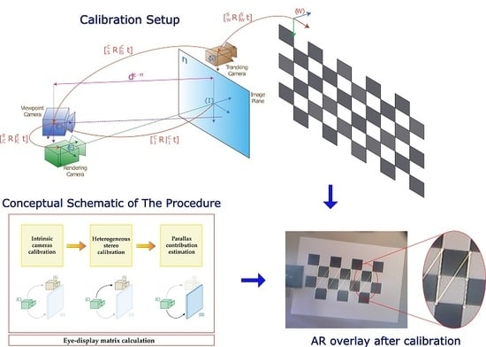
3.4. Formulation of the Calibration Procedure
As mentioned in the Introduction, calibration procedures of OST displays aim to achieve a perfect spatial alignment between a 3D real-world scene and the computer generated scene perceived through the display. To this end, we need to estimate the perspective projection matrix of the off-axis rendering camera that yields a correct mapping of each 3D vertex of the virtual object onto the imaging plane space . This 3D-2D mapping (i.e., process of rasterization) must be done in a way that all 3D vertexes along a ray that originates from the rendering camera center (i.e., the eye center ) is rendered at the same location on the virtual screen and perfectly aligned to their real counterpart. Our calibration procedure measures such a projection matrix by means of a camera that acts as a replacement of the user’s eye. Hereafter, we use the term viewpoint camera to refer to such a camera.
In our formulation, as well as in the implementation of the procedure, we exploit a vision based inside-out tracking technique as done in [
14,
16,
22]. Nonetheless, the same methodological guidelines that we here describe would also apply with an outside-in tracking technique, provided that it measures the pose of the sensor reference system, attached to the HMD,
with respect to the world scene
.
Figure 2 shows the spatial relationships between the coordinate systems associated with the tracking camera
, the internal viewpoint camera
(the user’s eye replacement), and the rendering camera
.
The first step in our calibration procedure is the estimation of the viewpoint camera projection matrix that maps world points
onto camera image points
:
We determine the intrinsic matrix of the viewpoint camera
and the relative pose between the viewpoint camera and the tracking camera
with conventional calibration routines [
23] described in more detail in
Section 4.2, whereas the pose of the world scene
with respect to
is measured on-line by querying the tracking camera
. We used an OpenCV checkerboard as the target object for the inside-out tracking (see
Section 4.1).
Next, the key step in the procedure is the computation of the planar homography
between the two pinhole cameras
and
that enables the image points of the viewpoint camera
to be mapped onto the imaging plane of the see-through display (i.e., the virtual screen)
.
where the planar homography
can be broken down as follows [
24]:
In Equation (
7),
is the intrinsic matrix of the ideal on-axis camera model of the eye–display, whose entries are established considering the manufacturer’s specifications of the OST display. Notably, we assumed that the focal lengths on both the x-axis and y-axis were equal (
), meaning the display pixels were considered as being perfectly square:
where
and
are the horizontal and vertical field-of-view (FOV) of the OST display and
w and
h are its width and height in pixels.
The other entries of Equation (
8) are:
the rotation matrix between the imaging planes of the viewpoint camera and of the OST display ;
the virtual translation vector between the viewpoint camera and the rendering camera
. We also label such a vector as parallax contribution, given that it models the transformation between ideal
and real
based on a specific eye position (subscript
). This contribution is described in more detail in
Section 3.4.3;
the normal unit vector to the OST display screen in the viewpoint camera reference system ;
the distance between the viewpoint camera center and the imaging plane of the OST display .
In the next two subsections, we explain how we estimate each of the above listed unknown variables.
3.4.1. Estimation of the Imaging Plane Pose with Respect to the Viewpoint Camera
We determine the position
and orientation
(i.e., the virtual pose) of the imaging plane of the OST display with respect to the viewpoint camera by computing the location of a calibration checkerboard projected onto the imaging plane of the see-through display (see
Section 4).
The physical size of the checkerboard square is established by arbitrarily dictating the distance from the projection center to the imaging plane
and adopting the intrinsic parameters of the ideal on-axis eye–display model (Equation (
8)), as also suggested in [
25]. By observing such a checkerboard with the calibrated viewpoint camera, we are able to compute both
and
.
Notably, the translation vector is linearly proportional to ().
3.4.2. Estimation of the Rendering Camera Pose with Respect to the Viewpoint Camera
Given the pose of the imaging plane of the OST display with respect to a particular position of the viewpoint camera (i.e., ), we can retrieve the pose of the rendering camera relative to the viewpoint camera by considering the transformation that brings the imaging plane to the focal plane. This pose encapsulates the rotational contribution caused by the different orientations of the rendering and of the viewpoint camera and the parallax contribution, which is also proportional to the distance from the projection center to the imaging plane ().
Geometrically, it is easy to demonstrate the following relation, valid ∀
position (
Figure 3):
3.4.3. Meaning of the Parallax Contribution for the Off-Axis Eye–Display Pinhole Model
By plugging Equation (
5) into Equation (
6), we obtain:
Since
, which is the unit vector of the principal axis of the display, Equation (
10) becomes:
This can be rewritten as:
can be further processed using Equation (
9) and imposing
, given that
is defined up to a scale factor
:
Equation (
13) tells us that, to achieve an accurate spatial alignment between 3D real-world points and computer generated elements rendered by an OST display and observed by a specific viewpoint (
), each virtual 3D vertex
must be observed by an off-axis rendering camera whose projection matrix
is modeled as follows:
The extrinsic parameters of the camera are: . Unsurprisingly, the center of projection of the virtual rendering camera is the user’s eye (in our procedure, the viewpoint camera), whereas its orientation matches the display virtual screen’s orientation.
The intrinsic parameters of the off-axis camera are obtained by applying a homographic transformation to the ideal on-axis intrinsic matrix:
This homography allows computing the intrinsic matrix of the real off-axis eye–display system, and it encapsulates the shift and scaling effect (i.e., the parallax contribution) due to a particular position of the user’s eye.
The intrinsic matrix for a different viewpoint position
is:
Therefore, from simple algebraic manipulations, we can obtain the transformation matrix that enables us to pass from
to
:
From this, we derive the same relation presented in [
8] and in [
7]:
where
is the translation from the old viewpoint position to the new viewpoint position and where
.
3.4.4. Relation between the Optical Properties of the OST Display and Intrinsic Matrix of the Eye–Display Model
In any HMD, the role of the collimation optics is to display the microdisplay image so that it appears magnified at a comfortable viewing distance [
26]. Specifically, the imaging plane of many consumer level OST HMDs is at infinity (i.e., at a very far distance), and this happens if the microdisplay is located in close proximity of the focal point of the collimation optics. In this case, the light rays coming from each pixel of the microdisplay are arranged in a parallel pattern, and the virtual image perceived by the user, to a first approximation, is not subjected to any shift or scaling effect for different positions of the user’s eye within the display eye-motion-box area.
Thereby, for those OST displays, the position of the user’s eye does not influence the intrinsic matrix of the off-axis eye–display pinhole camera model
, and this implies that the intrinsic linear parameters of the eye–display can be considered as parallax-free:
since
.
In this case, the on-line refinement step accounting for the user’s eye position is not needed. Differently, for those OST displays with shorter focal distances (e.g., Microsoft HoloLens, Magic Leap, Epson Moverio BT-200), the light rays within the eye-motion-box of the display are not parallel. For this reason, the contribution of the position of the user’s eye to the intrinsic matrix cannot be neglected, and the update contribution expressed by Equation (
17) must be taken into consideration (i.e., the intrinsic matrix is not parallax-free).
4. Technical Implementation of the Procedure
4.1. Hardware Setup
Our calibration procedure is applicable to any OST HMD, with finite or infinite focal distance, based on waveguides or on large spherical or semispherical optical combiners.
We tested our method on a commercial binocular OST HMD (ARS.30 by Trivisio [
27]) appropriately reworked to embody a vision based inside-out tracking mechanism. The visor was provided with dual SXGA OLED panels with
resolution and with a pair of standard flat optical combiners tilted at about
. The two panels were controlled via HDMI. The diagonal FOV of the HMD was of
, which corresponded to
arcmin/pixel angular resolution. The eye-relief of the display was 30 mm, and the size of the eye-motion-box was
mm. The imaging plane of the OST display was projected at 500 mm (
mm).
Following a similar approach to our previous research works [
28,
29], we embedded the HMD in a 3D printed plastic shell; the plastic shell was designed to house a pair of liquid crystal (LC) shutters and a pair of stereo RGB cameras (Leopard Imaging LI-OV4689) for the inside-out tracking mechanism (
Figure 4). The LC panels were placed in front of the optical combiners of the HMD, and they could be electronically controlled so as to modify the transparency of the see-through display and switch from see-through state to occluded state. We used the occluded modality for the second step of the calibration, in which we projected a calibration checkerboard onto the imaging plane of the see-through display.
Figure 5 shows the experimental setup. In our procedure, we used a single camera inside-out tracking mechanism. The tracking cameras had
diagonal FOV, which, was associated with a
image resolution, yielding
arcmin/pixel angular resolution. As we will discuss in
Section 5, this particular feature enabled us to have a reference limit in the evaluation of the overall calibration accuracy.
In our tests, we performed the calibration on the right display. Therefore, we placed the viewpoint camera behind the right display at approximately the eye-relief distance from the flat combiner (i.e., mm).
The viewpoint camera was a SONY FCB-MA130, which had a CMOS sensor, a resolution, and a diagonal FOV, which corresponded to arcmin/pixel.
Both the HMD and the validation checkerboard were locked to two rigid and adjustable holders. The validation checkerboard was a standard
OpenCV calibration checkerboard with a square size of 30 mm. The checkerboard was placed at approximately 650 mm of distance from the viewpoint camera. We attached the viewpoint camera to a 3D printed mounting template. The mounting template was equipped with fixing holes for placing the camera in eight pre-set positions radially arranged within the eye-motion-box of the see-through display (
Figure 6). The template and the camera were both anchored to the translation bar of the HMD holder.
We calibrated the display for the left position (reference position), and then, we computed the intrinsic matrix of the eye–display for the remaining seven positions using Equation (
17), where
is given by Equation (
9) and where the translation vector
is computed using two stereo calibrations between the tracking camera (fixed) and the viewpoint camera in the reference and in the new position:
4.2. Calibration Software
As outlined in
Section 3.4, the calibration workflow was broken down into four main steps, each of which was associated with a different software routine:
Estimation of the intrinsic camera parameters of both the viewpoint camera and the tracking camera (intrinsic camera calibrations).
Estimation of the pose of the tracking camera with respect to the viewpoint camera (heterogeneous stereo calibration).
Estimation of the pose of the rendering camera with respect to the viewpoint camera (parallax contribution estimation).
Estimation of the final eye–display projection matrix (eye–display matrix calculation).
The calibration workflow is depicted in
Figure 7. The details of the calibration steps are presented in the next subsections.
4.2.1. Intrinsic Camera Calibrations
The viewpoint camera and the tracking camera were calibrated with a conventional calibration technique [
23] that required storing multiple camera views of a planar pattern (i.e., OpenCV checkerboard). Linear parameters (i.e., intrinsic camera matrix) and non-linearities due to camera lens distortion (i.e., distortion parameters) were computed using non-linear least-squares minimization (i.e., the Levenberg–Marquardt algorithm). This procedure was performed using the MATLAB camera calibration toolbox (R2018b MathWorks, Inc., Natick, MA, USA).
4.2.2. Heterogeneous Stereo Calibration
The relative pose between the viewpoint camera and the tracking camera was estimated through a stereo calibration routine specific for two different camera types. This algorithm was developed in C++ under the Linux Operating System (Ubuntu 16.04) and using the OpenCV API 3.3.1 [
30].
4.2.3. Parallax Contribution and Eye–Display Matrix Estimation
The output of the heterogeneous stereo calibration algorithm, together with the intrinsic parameters of the two physical cameras and the manufacturer’s ideal projection parameters of the display were all fed into the final calibration routine. This routine was developed in MATLAB.
As described in
Section 3.4, the pose of the OST display imaging plane with respect to the viewpoint camera was determined as follows: a calibration checkerboard was projected onto the imaging plane of the occluded see-through display in full-screen modality and acquired by the viewpoint camera; the virtual pose of the imaging plane was determined through a standard perspective-n-point algorithm [
31]. These final data enabled us to compute the projection parameters of the off-axis eye–display model.
5. Experiments and Results
A dedicated software application was developed in MATLAB to validate the accuracy of the calibration technique. In the application, we generated a virtual scene whose virtual viewpoint (i.e., rendering camera) was controlled according to the extrinsic and the intrinsic parameters of the eye–display model determined from the calibration. In this way, we created an AR OST visualization, whose overlay accuracy could be considered as an objective evaluation metric for the calibration procedure. We therefore elaborated the image frames of the viewpoint camera and measured the overlay error, or reprojection error, between real and virtual features.
As ground truth real features, we considered the corners of the validation checkerboard, whereas as virtual features, we used virtual circles. The overlay error was computed as the Euclidean distance (
) between the image coordinates of the real and virtual features (
Figure 8).
We exploited the hybrid nature of the HMD, which can work both under OST and the video see-through modality [
28], to measure the overlay error as follows:
The image coordinates of the checkerboard corners were extracted by processing a frame of the viewpoint camera acquired with both the display and the optical shutter turned off. In order to do this, we used the MATLAB corner detection algorithm (
Figure 9b).
The image coordinates of the virtual landmarks were extracted by processing the viewpoint camera image without the real-world background, hence with both the display and the optical shutter turned on. The coordinates of the centroids of the virtual circles were retrieved using a semi-automatic centroid detection algorithm (
Figure 9c).
5.1. Quantitative Evaluation of Virtual-to-Real Registration Accuracy
Quantitative results are presented in terms of the average value, standard deviation, and max value of the overlay error (
) onto the imaging plane of the viewpoint camera over the eight positions on which the calibration was performed. Similarly, we also measured the values of the subtended angular error (
). Then, knowing the overlay error in pixels and given the distance
and the focal length of the viewpoint camera
, we also computed the associated absolute error in mm at the validation checkerboard plane by using the following relation: [
32,
33]:
5.2. Results and Discussion
Table 1 shows the results of the eight calibrations in terms of overlay error (
), angular error (
), and absolute error (
). The overall mean, standard deviation, and max values of
were
,
, and
px; the same values for
were
,
, and
arcmin and for
,
, and
mm.
The average overlay error for the reference position was comparable to that obtained by Owen et al. [
14] and by Gilson et al. [
16], whereas for the remaining positions, the average overlay error was comparable to that obtained in [
9] and in [
8]. It should be also noted that the results of the angular error are reported considering the rather low angular resolution of the viewpoint camera (≈2.67 arcmin/pixel). This explained the values of the angular errors obtained. If we considered the absolute error at the distance where the validation checkerboard was placed (≈650 mm), our results were comparable to those obtained with the camera based triangulation approach proposed by Klemm et al. [
20]. The experiment results suggested that the calibration refinement step accounting for the user’s eye position was paramount to achieve accurate results also for eye positions different from the reference one for all those OST HMDs with finite focal distances (i.e., not parallax-free OST HMDs). This was in accordance with what was suggested by Owen et al. [
14] and contrary to what was hypothesized by Gilson et al. and by [
34] et al. It should be also stressed that this assumption was clearly different from what was suggested in [
20] (page 58), where the classification of the OST HMDs was made based on the level of complexity of the OST optical combiner: “these results show that the triangulation approach only works for OSTG with simple optics and that it is not a universal approach”.
Overall, there were at least two sources of calibration inaccuracies in our method, both of which could be easily addressed in the future. The first one was not due to the calibration procedure per se, but it was due to the intrinsic tracking accuracy of the inside-out mechanism adopted in our study, which, as anticipated, was affected by the angular resolution of the tracking camera (i.e., ≈4.8 arcmin/pixel). This choice was dictated by the need to offer sufficient stereo overlap between the two tracking cameras, albeit at the expense of a reduced pixel density. It should be noted that this value of angular resolution had a detrimental effect on the calibration results as it increased the uncertainty in estimating the position of the validation checkerboard. This measure was used both for calibrating the eye–display model for the reference position of the viewpoint camera and also for computing the translation vector . We believe that in the future, the accuracy of the off-line phase of the calibration would benefit from the selection of tracking cameras with a higher value of angular resolution, achievable by selecting cameras with a higher image resolution or with longer focus lenses.
A second source of inaccuracy arose from not considering, in our solution, the contribution of the display optical distortion. Indeed, the collimation optics of any OST HMDs, despite being essential to provide a reasonable FOV and a comfortable viewing distance for the virtual image, is a source of optical distortions such as radial and tangential distortions [
35]. The same can be said for the optical combiner, particularly for waveguide based OST displays [
20]. These optical distortions not only affect the shapes of the virtual objects perceived by the user, but they also distort the pattern of binocular disparities between the left and right virtual images, and therefore, they alter the stereoscopic perception of the virtual content [
36]. To counter this problem, we are currently working on a solution that integrates a non-linear optimization step in the calibration algorithm. This further step can enable us to estimate the optical distortion parameters (radial and tangential). By doing so, we can correctly compensate for the optical distortions through a predistortion technique based on a 2D non-linear mapping of the virtual image on the imaging plane, as done in [
25].
In order for the distortion correction, as well as the transformation (
17) to be efficient and real time, a GPU based texture mapping approach (i.e., late warping) should be also adopted [
37]. This mechanism would require the use of an eye tracking camera. On account of this, our calibration procedure potentially can be integrated in the low level rendering mechanism of commercial OST HMDs to encompass the linear and non-linear 2D warping of the ideal imaging plane yielded by the intrinsic optical properties of the display and by the user’s eye position [
38].
6. Conclusions and Future Work
In this paper, we presented a method to easily calibrate OST HMDs based on the use of a calibrated camera replacing the user’s eye. The method, which could work with any type of OST HMD, only required the camera to observe a planar calibration pattern displayed on the imaging plane of the see-through display.
The method exploited standard camera calibration and computer vision techniques for estimating the projection parameters of the off-axis display model for a generic position of the viewpoint camera. In a prior-to-use second phase, the projection parameters were then refined through a planar homography that encapsulated the shift and scaling effect (i.e., the parallax contribution) associated with the relative translation from the old camera position to the current user’s eye position.
To evaluate the efficacy of the calibration technique objectively, we measured the overlay error between real and virtual features observed by the viewpoint camera from different positions within the eye-motion-box of the display. Experimental results indicated that the average overlay error of our calibration was pixel.
Our future work involves the integration of an additional step in the off-line calibration procedure devoted to the estimation of the radial and tangential distortion coefficients due to the lens system of the OST display. This calibration step can be performed through a non-linear optimization method such as the Levenberg–Marquardt algorithm.
We are also working on the integration of an eye tracking camera with our custom made OST HMD to perform user studies to evaluate the efficacy of the run-time refinement of the linear and non-linear calibration parameters and to design possible algorithm improvements that take into consideration the eye model.
Finally, the flexibility of our camera based calibration procedure can pave the way toward the profitable use of consumer level OST HMDs also in those applications that demand high accuracy in the spatial alignment between computer generated elements and the real-world scene (e.g., in surgical or high precision industrial applications).
Author Contributions
Conceptualization, F.C.; methodology, F.C., U.F., and N.C.; software, F.C., U.F., and N.C.; validation, F.C., U.F., N.C., and V.F.; formal analysis, F.C.; investigation, F.C. and U.F.; resources, F.C. and V.F.; data curation, U.F. and N.C.; writing, original draft preparation, F.C.; writing, review and editing, F.C., U.F., and N.C.; visualization, F.C.; supervision, F.C. and V.F.; project administration, V.F.; funding acquisition, V.F. All authors have read and agreed to the published version of the manuscript.
Funding
This research was supported by the HORIZON2020 Project VOSTARS (Video-Optical See Through AR surgical System), Project ID: 731974. Call: ICT-29-2016 Photonics KET2016.
Acknowledgments
The authors would like to thank Renzo D’Amato for his support in designing and assembling the AR visor.
Conflicts of Interest
The authors declare no conflict of interest. The funders had no role in the design of the study; in the collection, analyses, or interpretation of the data; in the writing of the manuscript; nor in the decision to publish the results.
Abbreviations
The following abbreviations are used in this manuscript:
| AR | Augmented reality |
| HMD | Head mounted display |
| OST | Optical see-through |
| SPAAM | Single point active alignment method |
| FOV | Field-of-view |
References
- Liu, H.; Auvinet, E.; Giles, J.; Rodriguez y Baena, F. Augmented Reality Based Navigation for Computer Assisted Hip Resurfacing: A Proof of Concept Study. Ann. Biomed. Eng. 2018, 46, 1595–1605. [Google Scholar] [CrossRef] [PubMed] [Green Version]
- Chen, L.; Day, T.W.; Tang, W.; John, N.W. Recent Developments and Future Challenges in Medical Mixed Reality. In Proceedings of the 2017 IEEE International Symposium on Mixed and Augmented Reality (ISMAR 2017), Nantes, France, 9–13 October 2017; pp. 123–135. [Google Scholar] [CrossRef] [Green Version]
- Zhou, F.; Duh, H.B.; Billinghurst, M. Trends in augmented reality tracking, interaction and display: A review of ten years of ISMAR. In Proceedings of the 2008 7th IEEE/ACM International Symposium on Mixed and Augmented Reality (ISMAR 2008), Cambridge, UK, 14–18 September 2008; pp. 193–202. [Google Scholar] [CrossRef] [Green Version]
- Qian, L.; Azimi, E.; Kazanzides, P.; Navab, N. Comprehensive tracker based display calibration for holographic optical see-through head-mounted display. arXiv 2017, arXiv:1703.05834. [Google Scholar]
- Cutolo, F. Letter to the Editor on “Augmented Reality Based Navigation for Computer Assisted Hip Resurfacing: A Proof of Concept Study”. Ann. Biomed. Eng. 2019, 47, 2151–2153. [Google Scholar] [CrossRef] [PubMed]
- Jones, J.A.; Edewaard, D.; Tyrrell, R.A.; Hodges, L.F. A schematic eye for virtual environments. In Proceedings of the 2016 IEEE Symposium on 3D User Interfaces (3DUI 2016), Greenville, SC, USA, 19–20 March 2016; pp. 221–230. [Google Scholar] [CrossRef]
- Grubert, J.; Itoh, Y.; Moser, K.; Swan, J.E. A Survey of Calibration Methods for Optical See-Through Head-Mounted Displays. IEEE Trans. Vis. Comput. Graph. 2018, 24, 2649–2662. [Google Scholar] [CrossRef] [PubMed] [Green Version]
- Itoh, Y.; Klinker, G. Interaction-free calibration for optical see-through head-mounted displays based on 3D Eye localization. In Proceedings of the 2014 IEEE Symposium on 3D User Interfaces (3DUI 2014), Minneapolis, MN, USA, 19–20 March 2014; pp. 75–82. [Google Scholar] [CrossRef]
- Tuceryan, M.; Navab, N. Single point active alignment method (SPAAM) for optical see-through HMD calibration for AR. In Proceedings of the IEEE and ACM International Symposium on Augmented Reality (ISAR 2000), Munich, Germany, 5–6 October 2000; pp. 149–158. [Google Scholar] [CrossRef] [Green Version]
- Navab, N.; Zokai, S.; Genc, Y.; Coelho, E.M. An on-line evaluation system for optical see-through augmented reality. In Proceedings of the IEEE Virtual Reality 2004 (IEEE VR 2004), Chicago, IL, USA, 27–31 March 2004; pp. 245–246. [Google Scholar] [CrossRef]
- Plopski, A.; Itoh, Y.; Nitschke, C.; Kiyokawa, K.; Klinker, G.; Takemura, H. Corneal-Imaging Calibration for Optical See-Through Head-Mounted Displays. IEEE Trans. Vis. Comput. Graph. 2015, 21, 481–490. [Google Scholar] [CrossRef] [PubMed]
- Genc, Y.; Tuceryan, M.; Navab, N. Practical solutions for calibration of optical see-through devices. In Proceedings of the IEEE and ACM International Symposium on Mixed and Augmented Reality (ISMAR 2002), Darmstadt, Germany, 30 September–1 October 2002; pp. 169–175. [Google Scholar] [CrossRef] [Green Version]
- Makibuchi, N.; Kato, H.; Yoneyama, H. Vision based robust calibration for optical see-through head-mounted displays. In Proceedings of the IEEE International Conference on Image Processing (ICIP 2013), Melbourne, Australia, 15–18 September 2013; pp. 2177–2181. [Google Scholar] [CrossRef]
- Owen, C.B.; Zhou, J.; Tang, A.; Xiao, F. Display-relative calibration for optical see-through head-mounted displays. In Proceedings of the IEEE and ACM International Symposium on Mixed and Augmented Reality (ISMAR 2004), Arlington, VA, USA, 2–5 November 2004; pp. 70–78. [Google Scholar] [CrossRef]
- Figl, M.; Ede, C.; Hummel, J.; Wanschitz, F.; Ewers, R.; Bergmann, H.; Birkfellner, W. A fully automated calibration method for an optical see-through head-mounted operating microscope with variable zoom and focus. IEEE Trans. Med Imaging 2005, 24, 1492–1499. [Google Scholar] [CrossRef] [PubMed]
- Gilson, S.J.; Fitzgibbon, A.W.; Glennerster, A. Spatial calibration of an optical see-through head-mounted display. J. Neurosci. Methods 2008, 173, 140–146. [Google Scholar] [CrossRef] [PubMed] [Green Version]
- Itoh, Y.; Klinker, G. Performance and sensitivity analysis of INDICA: INteraction-Free DIsplay CAlibration for Optical See-Through Head-Mounted Displays. In Proceedings of the 2014 IEEE International Symposium on Mixed and Augmented Reality (ISMAR 2014), Munich, Germany, 10–12 September 2014. [Google Scholar]
- Plopski, A.; Orlosky, J.; Itoh, Y.; Nitschke, C.; Kiyokawa, K.; Klinker, G. Automated Spatial Calibration of HMD Systems with Unconstrained Eye-cameras. In Proceedings of the 2016 IEEE International Symposium on Mixed and Augmented Reality (ISMAR 2016), Merida, Mexico, 19–23 September 2016; pp. 94–99. [Google Scholar] [CrossRef]
- Zhang, Z.; Weng, D.; Liu, Y.; Yongtian, W. A Modular Calibration Framework for 3D Interaction System Based on Optical See-Through Head-Mounted Displays in Augmented Reality. In Proceedings of the 2016 International Conference on Virtual Reality and Visualization (ICVRV), Tokyo, Japan, 11–13 May 2016; pp. 393–400. [Google Scholar] [CrossRef]
- Klemm, M.; Seebacher, F.; Hoppe, H. High accuracy pixel-wise spatial calibration of optical see-through glasses. Comput. Graph. 2017, 64, 51–61. [Google Scholar] [CrossRef]
- Fontana, U.; Cutolo, F.; Cattari, N.; Ferrari, V. Closed - Loop Calibration for Optical See-Through Near Eye Display with Infinity Focus. In Proceedings of the 2018 IEEE International Symposium on Mixed and Augmented Reality Adjunct (ISMAR-Adjunct 2018), Munich, Germany, 16–20 October 2018; pp. 51–56. [Google Scholar] [CrossRef]
- Genc, Y.; Tuceryan, M.; Khamene, A.; Navab, N. Optical see-through calibration with vision based trackers: Propagation of projection matrices. In Proceedings of the IEEE and ACM International Symposium on Augmented Reality (ISAR 2001), New York, NY, USA, 29–30 October 2001; pp. 147–156. [Google Scholar] [CrossRef] [Green Version]
- Zhang, Z. A flexible new technique for camera calibration. IEEE Trans. Pattern Anal. Mach. Intell. 2000, 22, 1330–1334. [Google Scholar] [CrossRef] [Green Version]
- Hartley, R.; Zisserman, A. Multiple View Geometry in Computer Vision; Cambridge books online; Cambridge University Press: Cambridge, UK, 2003. [Google Scholar]
- Lee, S.; Hua, H. A Robust Camera-Based Method for Optical Distortion Calibration of Head-Mounted Displays. J. Disp. Technol. 2015, 11, 845–853. [Google Scholar] [CrossRef]
- Holliman, N.S.; Dodgson, N.A.; Favalora, G.E.; Pockett, L. Three-Dimensional Displays: A Review and Applications Analysis. IEEE Trans. Broadcast. 2011, 57, 362–371. [Google Scholar] [CrossRef]
- Trivisio, Lux Prototyping sarl. Available online: https://www.trivisio.com/ (accessed on 24 December 2019).
- Cutolo, F.; Fontana, U.; Carbone, M.; D’Amato, R.; Ferrari, V. [POSTER] Hybrid Video/Optical See-Through HMD. In Proceedings of the 2017 IEEE International Symposium on Mixed and Augmented Reality (ISMAR-Adjunct 2017), Nantes, France, 9–13 October 2017; pp. 52–57. [Google Scholar] [CrossRef] [Green Version]
- Cutolo, F.; Fontana, U.; Ferrari, V. Perspective Preserving Solution for Quasi-Orthoscopic Video See-Through HMDs. Technologies 2018, 6, 9. [Google Scholar] [CrossRef] [Green Version]
- OpenCV, Open Source Computer Vision library. Available online: https://opencv.org/ (accessed on 24 December 2019).
- Gao, X.-S.; Hou, X.-R.; Tang, J.; Cheng, H.-F. Complete solution classification for the perspective-three-point problem. IEEE Trans. Pattern Anal. Mach. Intell. 2003, 25, 930–943. [Google Scholar] [CrossRef]
- Müller, M.; Rassweiler, M.C.; Klein, J.; Seitel, A.; Gondan, M.; Baumhauer, M.; Teber, D.; Rassweiler, J.J.; Meinzer, H.P.; Maier-Hein, L. Mobile augmented reality for computer-assisted percutaneous nephrolithotomy. Int. J. Comput. Assist. Radiol. Surg. 2013, 8, 663–675. [Google Scholar] [CrossRef] [PubMed]
- Ferrari, V.; Viglialoro, R.M.; Nicoli, P.; Cutolo, F.; Condino, S.; Carbone, M.; Siesto, M.; Ferrari, M. Augmented reality visualization of deformable tubular structures for surgical simulation. Int. J. Med Robot. Comput. Assist. Surg. 2016, 12, 231–240. [Google Scholar] [CrossRef] [PubMed]
- Oishi, T.; Tachi, S. Methods to Calibrate Projection Transformation Parameters for See-through Head-mounted Displays. Presence Teleoper. Virtual Environ. 1996, 5, 122–135. [Google Scholar] [CrossRef]
- Robinett, W.; Rolland, J.P. Computational model for the stereoscopic optics of a head-mounted display. In Stereoscopic Displays and Applications II; Merritt, J.O., Fisher, S.S., Eds.; International Society for Optics and Photonics: Bellingham, WA, USA, 1991; Volume 1457, pp. 140–160. [Google Scholar] [CrossRef]
- Cattari, N.; Cutolo, F.; D’amato, R.; Fontana, U.; Ferrari, V. Toed-in vs Parallel Displays in Video See-Through Head-Mounted Displays for Close-Up View. IEEE Access 2019, 7, 159698–159711. [Google Scholar] [CrossRef]
- Watson, B.A.; Hodges, L.F. Using texture maps to correct for optical distortion in head-mounted displays. In Proceedings of the Virtual Reality Annual International Symposium ’95 (VRAIS ’95), Research Triangle Park, NC, USA, 11–15 March 1995; pp. 172–178. [Google Scholar] [CrossRef]
- Bax, M.R. Real-time lens distortion correction: 3D video graphics cards are good for more than games. Stanford ECJ 2004, 1, 9–13. [Google Scholar] [CrossRef]
© 2019 by the authors. Licensee MDPI, Basel, Switzerland. This article is an open access article distributed under the terms and conditions of the Creative Commons Attribution (CC BY) license (http://creativecommons.org/licenses/by/4.0/).


