Article

An Investigation of Instability on Constant Shear Drained (CSD) Path under the CSSM Framework: A DEM Study

by
Hoang Bao Khoi Nguyen
*,
Md Mizanur Rahman
and
Md Rajibul Karim
UniSA STEM, University of South Australia, Adelaide, SA 5095, Australia
*
Author to whom correspondence should be addressed.
Geosciences 2022, 12(12), 449; https://doi.org/10.3390/geosciences12120449
Submission received: 7 November 2022 / Revised: 1 December 2022 / Accepted: 2 December 2022 / Published: 6 December 2022
(This article belongs to the Special Issue Assessment of Earthquake-Induced Soil Liquefaction Hazard)

Abstract

:
Soil liquefaction or instability, one of the most catastrophic phenomena, has attracted significant research attention in recent years. The main cause of soil liquefaction or instability is the reduction in the effective stress in the soil due to the build-up of pore water pressure. Such a phenomenon has often been thought to be related to the undrained shearing of saturated or nearly saturated sandy soils. Notwithstanding, many researchers also reported soil instability under a drained condition due to the reduction in lateral stress. This condition is often referred to as the constant shear drained (CSD) condition, and it is not uncommon in nature, especially in a soil slope. Even though several catastrophic dam failures have been attributed to CSD failure, the failure mechanisms in CSD conditions are not well understood, e.g., how the volumetric strain or effective stress changes at the triggering of flow deformation. Researchers often consider the soil fabric to be one of the contributors to soil behaviour and use this parameter to explain the failure mechanism of soil. However, the soil fabric is difficult to measure in conventional laboratory tests. Due to that reason, a numerical approach capable of capturing the soil fabric, the discrete element method (DEM), is used to investigate the CSD shearing mechanism. A series of simulations on 3D assemblies of ellipsoid particles was conducted. The DEM specimens exhibited instability behaviour when the effective stress paths nearly reached the critical state line. It can be clearly observed that the axial and volumetric strains changed suddenly when the stress states were close to the critical state line. Alongside these micromechanical observations, the study also presents deeper insights into soil behaviour by relating the macro-observations to the micromechanical aspect of the soil.

1. Introduction

Assessing soil liquefaction potential has been well covered in laboratory experiments [1,2,3,4,5,6,7,8,9,10,11,12,13]. Some studies assessed liquefaction potential by considering the dissipated energy approach [1,12,14,15,16,17,18]. Among the liquefaction assessment methods, the triaxial test is commonly adopted to predict the liquefaction potential under the critical state soil mechanics (CSSM) framework [2,3,5,19,20,21,22,23,24]. Such a test is performed by controlling the principal stress and strain components in 3 orthogonal directions, where σ′11 and ε11 are the major principal effective stress and strain, respectively, and σ′33 (equal to σ′22) and ε33 (i.e., equal to ε22) are the minor principal effective stress and strain, respectively. It has been consistently reported that there are three undrained behaviours for granular materials, which are non-flow, limited flow, and flow, as shown in Figure 1.
Note that it has been comprehensively discussed whether the CS and steady state (SS) are describing the same behaviour of soil [24,28]. Been, et al. [3] summarised studies of the CS commonly focused on the dilative behaviour of dense samples by using strain-rate controlled drained tests, while SS studies usually investigated the contractive behaviour of loose samples by applying undrained tests. After that, many studies reported that the CS or SS lines should be unique to the soil and used the two terminologies (CS and SS) interchangeably [19,22,27,29,30,31,32]. Since then, the research in liquefaction assessment has considered the equivalence of the CS and SS. For consistency, this research considered the terminology of the CS for the analysis.
The non-flow behaviour is often observed in dense soil and is associated with strain hardening during undrained shearing, while the limited flow and flow behaviours exhibit the strain softening after initial peak q; where q = (σ′11 − σ′33). The limited flow and flow behaviours are referred to as static liquefaction in the CSSM framework. A series of experimental studies have been conducted to understand the mechanism of these responses and to predict the liquefaction potential.
On the other hand, there are two commonly reported types of drained behaviours of soil, which are dilative and contractive responses [33,34,35]. Dilative behaviour in drained shearing is associated with volumetric dilation, while contractive behaviour is associated with volumetric contraction, and volume in the triaxial condition is often measured as volumetric strain (εv). It should be noted that the observed behaviour (drained or undrained) of soil highly depends on its initial state (i.e., initial void ratio, e0 and initial mean normal effective stress, p0); where p′ = (σ′11 + 2σ′33)/3.
With increasing deviatoric strain, εq = 2/3(ε11 − ε33), the soil will eventually reach an equilibrium state, at which there is no increment in stress (q or mean effective stress, p′), pore water pressure (Δu) and volume, i.e., dq = 0, dp′ = 0, dΔu = 0 and dεv = 0, regardless of its initial state; where ‘d’ denotes the rate of change. This equilibrium state is often called the critical state (CS) in both drained and undrained conditions, which has been commonly adopted by many researchers in the CSSM framework [2,3,36,37,38,39]. It has also been reported that CS data points from undrained and drained triaxial tests form a unique line for soil. It should be noted that CS may not be defined easily in some instances. Some of these may be overcome by extrapolation [27,39,40], and an acceptable critical state line (CSL) in the classical e-log(p′) space, with a tolerable scatter, can be achieved.
Both flow and limited flow responses in undrained conditions are often known as static liquefaction and are triggered at the instability stress ratio, ηIS (q/p′), which occurs at peak shear strength. The occurrence of static liquefaction in the field often leads to devastating effects, such as quick flow slides [41,42,43]. To assess the liquefaction potential of soil under undrained conditions, some researchers adopt the relationship between the triggering of instability and the state index [36,44]. In addition, the triggering of instability can also be found in drained conditions when the lateral stress keeps reducing. This behaviour is often called constant shear drained (CSD), which is quite common in soil slopes such as tailings dams. It has been found in the literature that the triggering of instability in CSD is associated with the triggering of instability in undrained conditions [45,46,47]. However, the experimental setups often have some challenges in capturing the particle arrangements of soil particles or soil fabric. It is well understood that soil fabric can decide the observed behaviour of soil [21,48,49,50,51,52]. Therefore, further research requires an alternative approach to access both micro- and macro-mechanical parameters of soil, as the failure mechanism under CSD conditions has yet to be fully understood.
Alternatively, the discrete element method (DEM), allowing access to micro-structure analysis, has gained more attention to study the micro-mechanical behaviour of granular material and develop the link between micro- and macro-mechanics [21,53,54,55]. It has also been proven that DEM has the capability of capturing the qualitative behaviour of granular materials, especially liquefaction or instability behaviour [22,32,56,57,58]. Such a technique also offers flexibility in controlling stress and strain to replicate different testing conditions of granular materials. So, the DEM stress-controlled simulations were performed to replicate the CSD condition in laboratory experiments. The findings from this study will provide more in-depth knowledge about the evolutions of micromechanical entities, such as the soil fabric (internal structure of soil) and contact density, which dictate the overall macro-mechanical behaviour of soils.

2. Materials and Methodology

2.1. Materials

As mentioned earlier, the numerical tool, DEM, was adopted in this study to investigate the particle interactions with the soil sample under CSD conditions. All simulations in this study were performed by an open-source DEM code called OVAL which was developed by Kuhn [55]. A linear contact model for force-displacement law and a periodic boundary were used in this study, wherein particles can overlap one another at their contacts by a small amount compared with their size, which is treated as the deformation of the particles. The maximum dimensionless overlap ratio for all assemblies in this study is very small, i.e., approximately 2.015 × 10⁻⁴. The coefficient of friction between the particles was considered 0.5, whereas both normal and tangential contact stiffnesses were kept at 108 N/m. It should be noted that a series of sensitivity studies check whether the simulations achieved numerical stability [59] and representative elementary volume (REV) condition [60]. Therefore, the model parameters used in this study were reasonable to capture the qualitative behaviour of granular materials in general. Furthermore, this study did not aim to model or match the mechanical behaviour of any particular soil. In addition, the grain size distribution of all specimens was maintained the same, and the elliptical shape was considered, as shown in Figure 2. The adoption of the elliptical shape gave some angularities for the particles and reduced the rolling tendency of the particles during the simulations. It can be noted that some DEM studies using spherical particles adopted a rolling resistance model to replicate the angularity features of the particle [48,61,62,63,64,65,66].
As mentioned previously, the behaviour of granular materials under CSD conditions is linked with the observed undrained behaviour [45,46,47]. Therefore, some undrained (constant volume) simulations were performed in DEM for the critical state soil mechanics (CSSM) investigations. Then, several CSD simulations were performed. The details of the simulations used can be found in Table 1. It should be noted that obtaining a reasonable critical state line (CSL) requires a comprehensive data set of triaxial tests. Therefore, this study also adopted the CS data from the previous study for the same granular materials (i.e., same model parameters, particle shape and grain size distribution), which can be found in Nguyen, et al. [67].

2.2. Methodology

As mentioned previously, two types of DEM simulation were considered in this study, i.e., constant volume or undrained simulations and drained-CSD simulations:
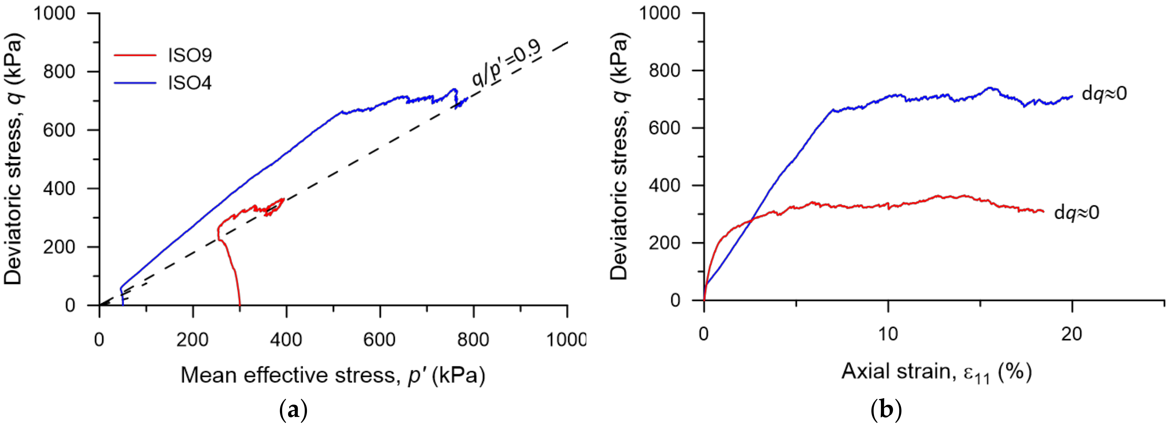
  • Undrained (constant volume) simulation: The specimens were subjected to isotropic stress in triaxial spaces during consolidation to achieve a targeted mean effective stress (p0). During undrained shearing, the volume of the specimen maintained constant at dεv = 0 with the increasing axial strain (ε11). Note that dεv = dε11 + dε22 + dε33.
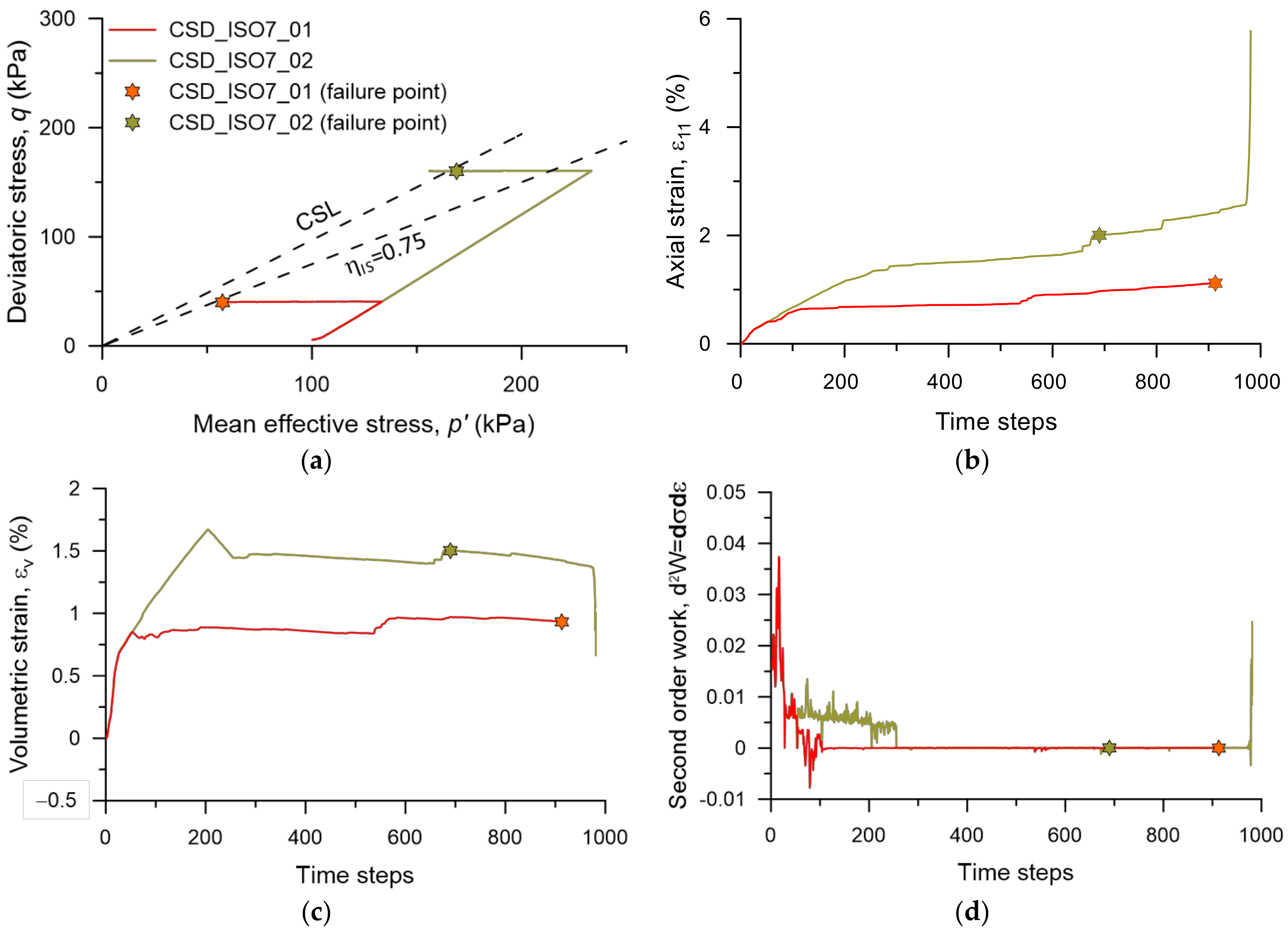
  • Drained—CSD simulation: The specimens were subjected to isotropic loads in triaxial spaces during consolidation to achieve a targeted mean effective stress (p0). The specimen was then subjected to drained shearing, in which the minor effective stress (σ′33) was kept unchanged to obtain the drained path, i.e., (dq/dp′ = 3). After reaching a certain value in the drained shearing, the CSD path was performed. During the CSD stage, dq was strictly maintained around zero and p′ was decreasing by controlling σ′11 and σ′33. The CSD simulations stopped when they approached the CSL. It should be noted that the stress path cannot go far beyond the CSL, as such a unique line defines the failure pattern for granular material.

3. Critical State Soil Mechanics Framework in DEM

The undrained simulations were performed until the CS reached dq = 0, dp′ = 0, dΔu = 0 and dεv = 0. Figure 3 shows two specimens exhibiting non-flow behaviour, i.e., q kept increasing. The CS stress ratios, M = q/p′ were found to be 0.9 for both simulations in Figure 3a. The M line is often referred to as the CS line (CSL) in the q-p′ space. Both effective stress paths of ISO4 (e0 = 0.582 and p0 = 50 kPa) and ISO9 (e0 = 0.625 and p0 = 300 kPa) showed very dilative tendencies and evolved beyond the CSL shown in Figure 3a. This phenomenon was also observed for different granular materials [66]. It can be clearly seen that q values for both simulations were approaching an equilibrium state, i.e., dq ≈ 0 after strain hardening (see Figure 3b). So, these data points were used to determine the CSL.
The CS data from the undrained simulations in this study and previous studies for the same granular materials formed a unique CSL in the q-p′ and e-log(p′) spaces (see Figure 4) [67,68]. The CSL or M line in Figure 4a has a slope of approximately 0.9. This line was used to examine the failure mechanism of CSD simulations. The CS data points in the classical e-log(p′) space formed a unique equation of e = 0.68 0.02 × p p a 0.73 ; where p a is the reference stress which is approximately 101 kPa [3,7,19]. The CSL is well known as the reference line to predict the liquefaction or instability behaviour of granular materials in the CSSM framework [2,3,69,70]. The specimen with the initial state starting above the CSL exhibits flow liquefaction under undrained conditions, whereas the specimen with the initial state starting below the CSL shows dilative or non-flow behaviour. It should be noted that some CS data points for very loose specimens starting above the CSL may fail before reaching CS, and those specimens often showed complete liquefaction behaviour (p′ ≈ 0 kPa). This resulted in some data points above CSL shown in Figure 4b.
Additionally, the DEM technique was adopted in this study so that the micro-mechanical entities during shearing could be captured. Two micro-mechanical entities considered in this study were contact density (coordination number, CN) and soil fabric (von Mises fabric, FvM). It has been consistently reported that the soil fabric shows a good correlation with the macro-mechanical parameters of the granular materials, and it has been adopted in many constitutive models [19,71,72,73,74]. Rothenburg and Bathurst [75] used the following equation to calculate C N .
C N = 2 N c / N p
where N c is the total number of contacts and N p is the total number of particles in a granular assembly. In addition, Satake [76] proposed a fabric tensor to quantify the structural anisotropy of the granular material as
F = F i j = 1 N c k = 1 N n i k n j k
where n k is the direction of the kth contact. A scalar quantity of F can be presented by von Mises fabric (FvM = 3 F J 2 D ), where F J 2 D is the second invariant of the deviatoric fabric tensor, as shown below.
F J 2 D =   1 6 F 11 F 22 2 + F 11 F 33 2 + F 22 F 33 2 + F 12 2 + F 13 2 + F 23 2
where F 11 , F 22 , and F 33 are the fabric in the principal directions and F 12 , F 13 , and F 23 are the fabric in the shear directions. It was found that the CS CN values also formed a unique relationship with the CS p′ i.e., e = 3.91 + 0.36 × p p a 0.55 in Figure 5a. However, the CS FvM did not show a very strong correlation with the CS p′ similar to other mechanical parameters. This is understandable, as it has been reported that such a parameter is sensitive during loading [57,67]. Despite the fluctuations, the relationship between FvM and p′ can be considered to form a narrow zone called the ‘CS zone’ in Figure 5b. All simulations should reach this CS zone at the end of shearing.

4. Instability Behaviour of Granular Materials

4.1. Flow Liquefaction under Undrained Condition

Flow liquefaction or instability is often associated with loose or very loose granular materials under undrained conditions. Two simulations, ISO7 (e0 = 0.660 and p0 = 100 kPa) and ISO12 (e0 = 0.676 and p0 = 200 kPa), in Figure 6 exhibited strain hardening until attaining an initial peak q. Then, q gradually reduced towards the CS. At the initial peak q, the triggering of liquefaction occurs. The stress ratio (q/p′) at this point is called the instability stress ratio (ηIS), which has been adopted widely in liquefaction prediction studies [27,47,76]. ηIS values for ISO7 and ISO12 were 0.75 and 0.45, respectively. Additionally, the effective stresses of the two simulations were approaching zero at the CS. This phenomenon is referred to as ‘complete liquefaction’, which has also been observed in many experimental studies [27,77,78,79,80].

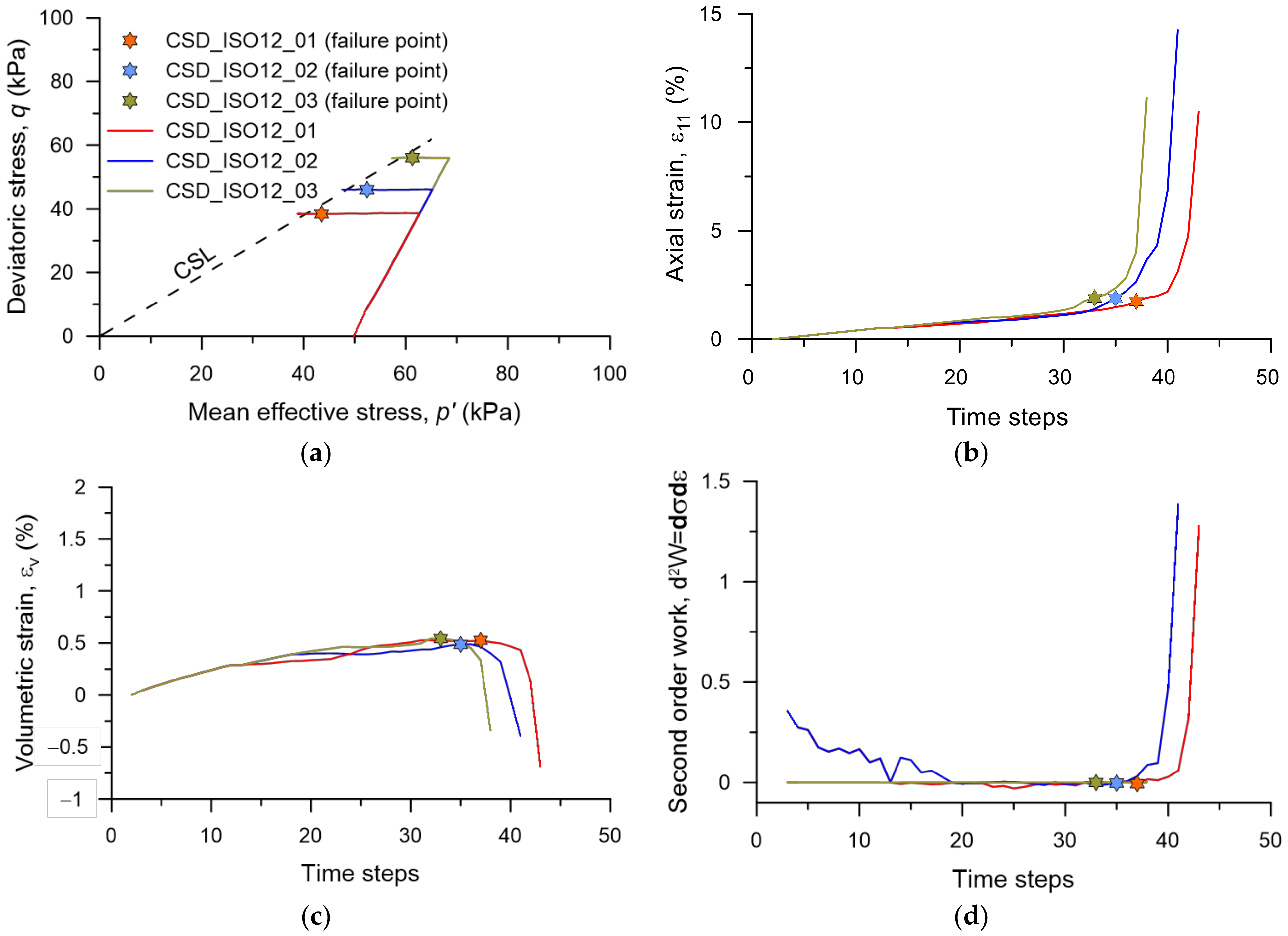
4.2. Instability during Constant Shear Drained Tests

It has been consistently reported that flow deformation does not only occur in undrained conditions but may also happen in drained conditions due to lateral stress relief. Such a phenomenon, also known as a constant shear drained (CSD) response, is not uncommon. The CSD conditions can also be investigated under the CSSM framework in laboratory settings [13,45,46,47,81]. The CSD simulations with the same initial states with ISO7 and ISO12 in Figure 6 were performed for further investigation. CSD_ISO7_01 and CSD_ISO7_02 having the same initial state with ISO7 were shown in Figure 7. In the initial stage of shearing, the drained condition was replicated until reaching a targeted q value in each test. In the next stage, q was maintained constant and p′ reduced until failure. CSD_ISO7_01 failed when it was approaching the instability line with ηIS of 0.75 (from Figure 6). However, CSD_ISO7_02 passed through the instability zone and only failed when approaching the CSL. After reaching the failure point around the CSL, CSD_ISO7_02 started to exhibit a significant change in ε11 and εv in Figure 7b,c. This observation is in line with some other experimental studies [45,46,47]. Moreover, a parameter, second order work (d2W), was adopted in this study to get a better understanding of the CSD mechanisms. This parameter is defined as the dot product of stress increment and plastic strain increment tensors [82], as shown in Equation (4).
d 2 W   =   d σ   d ε P
where σ is the stress tensor and ε P is the plastic strain tensor. Granular materials such as sand often show negligible elastic behaviour at large strain [19]. Therefore, it can be assumed that ε P is approximately equal to total strain tensor (ε). d 2 W in Figure 7d initially fluctuated but then became stable. However, it showed a sudden change after reaching the failure point. Note that some similar observations were found in previous studies [13,46,52], where d 2 W values of monotonic and cyclic loading simulations changed suddenly when approaching the triggering of instability.
Furthermore, the CSD simulations with the same initial state of ISO12, CSD_ISO12_01, CSD_ISO12_02, and CSD_ISO12_03 were shown in Figure 8. The three specimens started to fail when approaching the CSL, which was similar to what was observed in CSD_ISO7_02. Similarly, after reaching the failure point around the CSL, the three simulations started to exhibit significant changes in ε11, εv, and d 2 W , as shown in Figure 8b–d. The observations in this study were in line with the previous reports of constant shear failure. The triggering of failure often follows by a large deformation, i.e., strain increment. This causes the sudden change in stress and then the second order work, d 2 W .

4.3. CSSM Analysis for CSD Simulations

It was mentioned before the CSL in the e-log(p′) space is used as a reference line to determine the liquefaction potential of granular materials. Similarly, in micro-mechanics, the line formed by the CS CN and p′, or the zone formed by the CS FvM and p′, can also be used as a reference for such analysis. Five CSD simulations used in previous sections were plotted together with the CSL shown in Figure 9. In the e-log(p′) space, most simulations failed near the CSL. Only CSD_ISO7_02 crossed the CSL and then failed nearby. In Figure 9b, there were also sudden changes in CN after the simulations reached the failure point. For FvM in Figure 9c, the failure points were reached very close to the CS zone formed by the CS FvM. After the failure points, FvM values kept increasing towards the CS zone. The observations in CN and FvM proved that there were links between these micro-mechanical entities with the macro-mechanical parameters such as e. Therefore, in DEM studies, the evolutions of these micro-mechanical entities could be examined under the CSSM framework and adopted in the liquefaction study of granular materials.
Furthermore, instability behaviour has often been examined by correlating the instability stress ratio and the state parameter (ψ). ψ, one of the common state indices used in the CSSM framework, characterizes the distance between the state of soil and its CSL. In other words, the state parameter is the difference between the current void ratio (e) and the critical state void ratio (ecs). A positive ψ means contractive behaviour, whereas a negative ψ means dilative behaviour. In Figure 10, the instability line, the line of best fit for η and ψ at instability, was established by the undrained simulations (from limited flow and flow behaviour). The instability behaviour of CSD simulations was then investigated in the η-ψ space in Figure 10. It was found that most CSD simulations (CSD_ISO12_01, CSD_ISO12_02 and CSD_ISO12_03) crossed the instability line and then failed, which agreed with the literature [45,46]. Only CSD_07_01 failed before reaching the instability, and CSD_07_02 crossed the instability line twice before failure. Note that CSD_07_01 may experience some numerical instability at a low-stress level; therefore, the simulation stopped before reaching failure. However, all other simulations failed after crossing the instability line, which can be used in future liquefaction analysis. No simulations can cross the CSL from undrained simulations, which also aligns with the literature [45,46]. This confirmed that the CS theory can be well adopted to predict the triggering of instability from CSD test.

5. Conclusions

The liquefaction analysis under undrained and constant shear drained (CSD) conditions was performed in this study. The findings from this study are:
  • It is evident that the critical state line (CSL) obtained from the undrained simulations can be used as a reference line to predict the failure in the CSD conditions. It was reported that a large increment in strain was recorded when approaching the CS, which indicated the failure of the granular materials. This observation is in line with the previous experimental and numerical studies of granular materials’ behaviour.
  • It was also observed that most CSD simulations failed after crossing the instability line in the η-ψ space. This is in line with the findings from the theoretical CSSM framework. So, the instability line can be further used as the reference line to predict CSD failure.
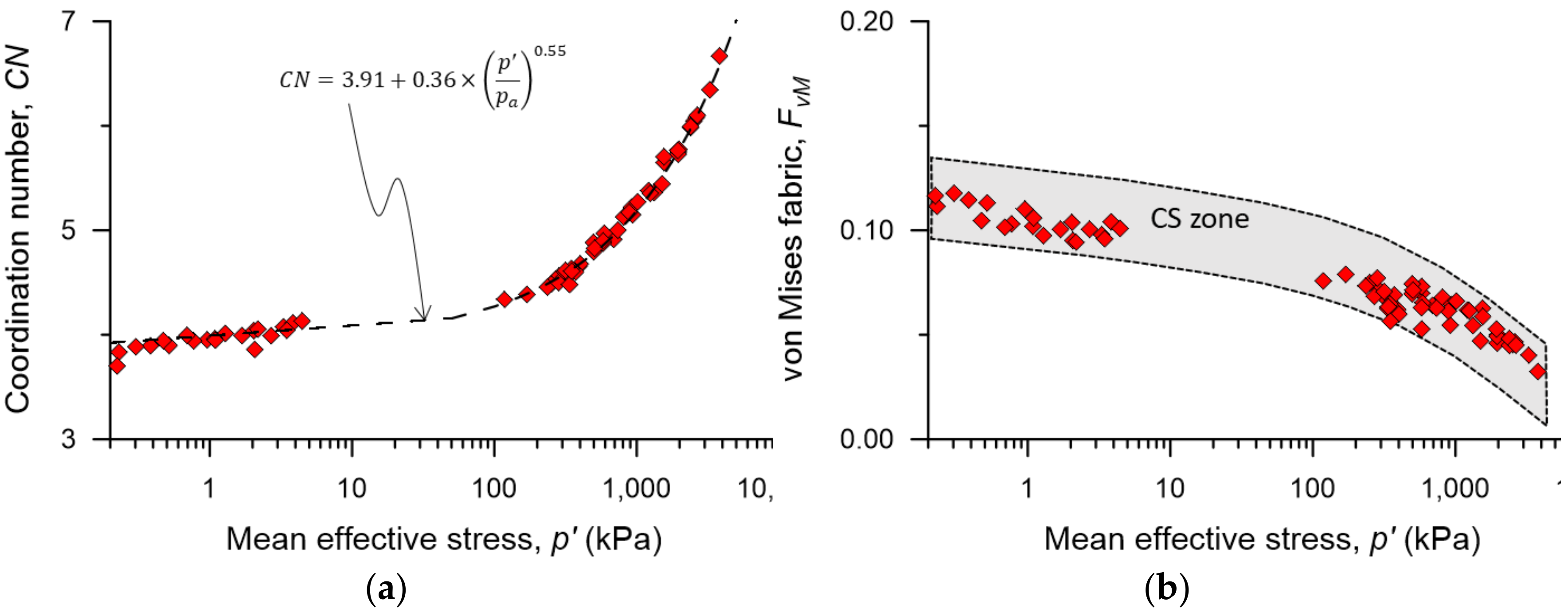
  • Additionally, the discrete element method (DEM) provides access to capture the micro-mechanical entities such as coordination number (CN) and von Mises fabric (FvM). These micro-mechanical entities were proven to be correlated well with the macro-mechanical parameters such as void ratio and confining stress. This finding will help to enhance the knowledge of granular materials’ behaviour at the microscopic level and can be potentially used in the future study of liquefaction or instability behaviour.
The knowledge from this study could be adopted to propose a prediction model for a soil slope, such as a tailings dam, a water retaining dam, etc., in which lateral stress relief may happen. However, it should be aware that some further analyses under the CSSM framework may be required for different granular materials.

Author Contributions

Conceptualization, H.B.K.N.; methodology, H.B.K.N. and M.M.R.; software, H.B.K.N.; validation, H.B.K.N., M.M.R. and M.R.K.; formal analysis, H.B.K.N., M.M.R. and M.R.K.; investigation, H.B.K.N., M.M.R. and M.R.K.; resources, H.B.K.N.; data curation, H.B.K.N.; writing—original draft preparation, H.B.K.N.; writing—review and editing, H.B.K.N., M.M.R. and M.R.K.; visualization, H.B.K.N. and M.M.R.; supervision, M.M.R. and M.R.K.; project administration, H.B.K.N. All authors have read and agreed to the published version of the manuscript.

Funding

This research received no external funding.

Institutional Review Board Statement

Not applicable.

Informed Consent Statement

Not applicable.

Conflicts of Interest

The authors declare no conflict of interest.

References

  1. Roscoe, K.H.; Schofield, M.A.; Worth, C.P. On the Yielding of Soils. Géotechnique 1958, 8, 22–53. [Google Scholar] [CrossRef]
  2. Schofield, A.N.; Wroth, P. Critical State Soil Mechanics; McGraw-Hill: London, UK, 1968; p. 310. [Google Scholar]
  3. Been, K.; Jefferies, M.; Hachey, J. The critical state of sands. Geotechnique 1991, 41, 365–381. [Google Scholar] [CrossRef]
  4. Chu, J.; Lo, S.R. On the measurement of critical state parameters of dense granular soils. Geotech. Test. J. 1993, 16, 27–35. [Google Scholar]
  5. Jefferies, M. Nor-Sand: A simple critical state model for sand. Géotechnique 1993, 43, 91–103. [Google Scholar] [CrossRef]
  6. Chu, J. An experimental examination of the critical state and other similar concepts for granular soils. Can. Geotech. J. 1995, 32, 1065–1075. [Google Scholar] [CrossRef]
  7. Manzari, M.T.; Dafalias, Y.F. A critical state two-surface plasticity model for sands. Géotechnique 1997, 47, 255–272. [Google Scholar] [CrossRef]
  8. Finno, R.J.; Rechenmacher, A.L. Effects of Consolidation History on Critical State of Sand. J. Geotech. Geoenviron. Eng. 2003, 129, 350–360. [Google Scholar] [CrossRef]
  9. Jefferies, M.; Been, K. Soil Liquefaction: A Critical State Approach; Taylor & Francis: Abingdon, UK, 2006. [Google Scholar]
  10. Le, T.-T.; Park, S.-S.; Woo, S.-W. Cyclic Response and Reconsolidation Volumetric Strain of Sand under Repeated Cyclic Shear Loading Events. J. Geotech. Geoenviron. Eng. 2022, 148, 04022109. [Google Scholar] [CrossRef]
  11. Guoxing, C.; Enquan, Z.; Zhihua, W.; Binghui, W.; Xiaojun, L. Experimental investigation on fluid characteristics of medium dense saturated fine sand in pre- and post-liquefaction. Bull. Earthq. Eng. 2016, 14, 2185–2212. [Google Scholar] [CrossRef]
  12. Baziar, M.H.; Jafarian, Y. Assessment of liquefaction triggering using strain energy concept and ANN model: Capacity Energy. Soil Dyn. Earthq. Eng. 2007, 27, 1056–1072. [Google Scholar] [CrossRef]
  13. Fotovvat, A.; Sadrekarimi, A.; Etezad, M. Instability of gold mine tailings subjected to undrained and drained unloading stress paths. Géotechnique 2022, 1–19. [Google Scholar] [CrossRef]
  14. Berrill, J.B.; Davis, R.O. Energy Dissipation and Seismic Liquefaction of Sands: Revised Model. Soils Found. 1985, 25, 106–118. [Google Scholar] [CrossRef] [PubMed] [Green Version]
  15. Green, R.A.; Mitchell, J.K.; Polito, C.P. An Energy-Based Excess Pore Pressure Generation Model for Cohesionless Soils. In Proceedings of the John Booker Memorial Symposium, Sydney, Australia, 6–17 November 2000; pp. 383–390. [Google Scholar]
  16. Lirer, S.; Mele, L. On the apparent viscosity of granular soils during liquefaction tests. Bull. Earthq. Eng. 2019, 17, 5809–5824. [Google Scholar] [CrossRef]
  17. Mele, L. An experimental study on the apparent viscosity of sandy soils: From liquefaction triggering to pseudo-plastic behaviour of liquefied sands. Acta Geotech. 2022, 17, 463–481. [Google Scholar] [CrossRef]
  18. Mele, L.; Flora, A. On the prediction of liquefaction resistance of unsaturated sands. Soil Dyn. Earthq. Eng. 2019, 125, 105689. [Google Scholar] [CrossRef]
  19. Li, X.; Dafalias, Y. Dilatancy for cohesionless soils. Geotechnique 2000, 50, 449–460. [Google Scholar] [CrossRef]
  20. Rahman, M.M.; Nguyen, H.B.K.; Rabbi, A.T.M.Z. The effect of consolidation on undrained behaviour of granular materials: A comparative study between experiment and DEM simulation. Geotech. Res. 2018, 5, 199–217. [Google Scholar] [CrossRef] [Green Version]
  21. Kuhn, M.R. The critical state of granular media: Convergence, stationarity and disorder. Géotechnique 2016, 66, 902–909. [Google Scholar] [CrossRef] [Green Version]
  22. Zhao, J.; Guo, N. Unique critical state characteristics in granular media considering fabric anisotropy. Géotechnique 2013, 63, 695–704. [Google Scholar] [CrossRef] [Green Version]
  23. Luong, M.; Sidaner, J. Undrained Behaviour of Cohesionless Soils under Cyclic and Transient Loading. In Proceedings of the 1st International Conference on Recent Advances in Geotechnical Earthquake Engineering and Soil Dynamics, St. Louis, MO, USA, 11–15 March 1981. [Google Scholar]
  24. Poulos, S.J. The steady state of deformation. J. Geotech. Eng. Div. 1981, 107, 553–562. [Google Scholar] [CrossRef]
  25. Kramer, S.; Seed, H. Initiation of soil liquefaction under static loading conditions. J. Geotech. Eng. 1988, 114, 412–430. [Google Scholar] [CrossRef]
  26. Ishihara, K. Liquefaction and flow failure during earthquakes. Geotechnique 1993, 43, 351–451. [Google Scholar] [CrossRef]
  27. Murthy, T.G.; Loukidis, D.; Carraro, J.A.H.; Prezzi, M.; Salgado, R. Undrained monotonic response of clean and silty sands. Geotechnique 2007, 57, 273–288. [Google Scholar] [CrossRef]
  28. Casagrande, A. Liquefaction and cyclic deformation of sands–A critical review. Harv. Soil Mech. Ser. 1976, 1–55. [Google Scholar]
  29. Rahman, M.M.; Lo, S.; Gnanendran, C. On equivalent granular void ratio and steady state behaviour of loose sand with fines. Can. Geotech. J. 2008, 45, 1439–1456. [Google Scholar] [CrossRef] [Green Version]
  30. Sitharam, T.; Vinod, J.S.; Ravishankar, B. Evaluation of undrained response from drained triaxial shear tests: DEM simulations and experiments. Geotechnique 2008, 58, 605–608. [Google Scholar] [CrossRef] [Green Version]
  31. Nguyen, H.B.K.; Rahman, M.M.; Fourie, A.B. Undrained behaviour of granular material and the role of fabric in isotropic and K0 consolidations: DEM approach. Géotechnique 2017, 67, 153–167. [Google Scholar] [CrossRef]
  32. Suzuki, K.; Kuhn, M.R. Uniqueness of Discrete Element Simulations in Monotonic Biaxial Shear Tests. Int. J. Geomech. 2014, 14, 06014010. [Google Scholar] [CrossRef]
  33. Sawicki, A.; Świdziński, W. Drained against undrained behaviour of sand. Arch. Hydro-Eng. Environ. Mech. 2007, 54, 207–222. [Google Scholar]
  34. Hanley, K.J.; Huang, X.; O’Sullivan, C. Energy dissipation in soil samples during drained triaxial shearing. Géotechnique 2018, 63, 421–433. [Google Scholar] [CrossRef] [Green Version]
  35. Lade, P.V.; Ibsen, L.B. A Study of the Phase Transformation and the Characteristic Lines of Sand Behaviour. In Proceedings of the Internatiol Symposium on Deformation and Progressive Failure in Geomechanics, Nagoya, Japan, 4–9 October 1997; pp. 353–359. [Google Scholar]
  36. Mizanur, R.M.; Lo, S. Predicting the onset of static liquefaction of loose sand with fines. J. Geotech. Geoenviron. Eng. 2012, 138, 1037–1041. [Google Scholar] [CrossRef]
  37. Rahman, M.; Lo, S. Undrained Behavior of Sand-Fines Mixtures and Their State Parameter. J. Geotech. Geoenviron. Eng. 2014, 140, 04014036. [Google Scholar] [CrossRef]
  38. Wei, X.; Yang, J. A critical state constitutive model for clean and silty sand. Acta Geotech. 2019, 14, 329–345. [Google Scholar] [CrossRef]
  39. Zhang, J.; Lo, S.-C.R.; Rahman, M.M.; Yan, J. Characterizing Monotonic Behavior of Pond Ash within Critical State Approach. J. Geotech. Geoenviron. Eng. 2018, 144, 04017100. [Google Scholar] [CrossRef]
  40. Carrera, A.; Coop, M.; Lancellotta, R. Influence of grading on the mechanical behaviour of stava tailings. Geotechnique 2011, 61, 935–946. [Google Scholar] [CrossRef]
  41. Lade, P.V.; Yamamuro, J.A. Evaluation of static liquefaction potential of silty sand slopes. Can. Geotech. J. 2011, 48, 247–264. [Google Scholar] [CrossRef]
  42. Olson, S.M.; Stark, T.D.; Walton, W.H.; Castro, G. 1907 static liquefaction flow failure of the north dike of wachusett dam. J. Geotech. Geoenviron. Eng. 2000, 126, 1184–1193. [Google Scholar] [CrossRef]
  43. Fourie, A.; Blight, G.; Papageorgiou, G. Static liquefaction as a possible explanation for the Merriespruit tailings dam failure. Can. Geotech. J. 2001, 38, 707–719. [Google Scholar] [CrossRef]
  44. Rabbi, A.T.M.Z.; Rahman, M.M.; Cameron, D.A. Undrained behavior of silty sand and the role of isotropic and K0 consolidation. J. Geotech. Geoenviron. Eng. 2018, 144, 04018014. [Google Scholar] [CrossRef]
  45. Lashkari, A.; Khodadadi, M.; Binesh, S.M.; Rahman, M.M. Instability of Particulate Assemblies under Constant Shear Drained Stress Path: DEM Approach. Int. J. Geomech. 2019, 19, 04019049. [Google Scholar] [CrossRef]
  46. Rabbi, A.T.M.Z.; Rahman, M.M.; Cameron, D.A. Critical State Study of Natural Silty Sand Instability under Undrained and Constant Shear Drained Path. Int. J. Geomech. 2019, 19, 04019083. [Google Scholar] [CrossRef]
  47. Alipour, M.J.; Lashkari, A. Sand instability under constant shear drained stress path. Int. J. Solids Struct. 2018, 150, 66–82. [Google Scholar] [CrossRef]
  48. Barnett, N.; Rahman, M.M.; Karim, M.R.; Nguyen, H.B.K. Evaluating the particle rolling effect on the characteristic features of granular material under the critical state soil mechanics framework. Granul. Matter 2020, 22, 89. [Google Scholar] [CrossRef]
  49. Nguyen, H.B.K.; Rahman, M.M.; Fourie, A. The critical state behaviour of granular material in triaxial and direct simple shear condition: A DEM approach. Comput. Geotech. 2021, 138, 104325. [Google Scholar] [CrossRef]
  50. Huang, M.; Chen, Y.; Gu, X. Discrete element modeling of soil-structure interface behavior under cyclic loading. Comput. Geotech. 2019, 107, 14–24. [Google Scholar] [CrossRef]
  51. Zhang, L.; Evans, T.M. Boundary effects in discrete element method modeling of undrained cyclic triaxial and simple shear element tests. Granul. Matter 2018, 20, 60. [Google Scholar] [CrossRef]
  52. Huang, X.; Kwok, C.-Y.; Hanley, K.J.; Zhang, Z. DEM analysis of the onset of flow deformation of sands: Linking monotonic and cyclic undrained behaviours. Acta Geotech. 2018, 13, 1061–1074. [Google Scholar] [CrossRef] [Green Version]
  53. Cundall, P.A.; Hart, R.D. Numerical modelling of discontinua. Eng. Comput. 1992, 9, 101–113. [Google Scholar] [CrossRef]
  54. Potyondy, D.O.; Cundall, P.A. A bonded-particle model for rock. Int. J. Rock Mech. Min. Sci. 2004, 41, 1329–1364. [Google Scholar] [CrossRef]
  55. Kuhn, M.R. OVAL and OVALPLOT: Programs for Analyzing Dense Particle Assemblies with the Discrete Element Method; Department of Civil Engineering, University of Portland: Portland, OR, USA, 2006. [Google Scholar]
  56. Kuhn, M.R. Dense granular flow at the critical state: Maximum entropy and topological disorder. Granul. Matter 2014, 16, 499–508. [Google Scholar] [CrossRef]
  57. Huang, X.; O’Sullivan, C.; Hanley, K.; Kwok, C. Discrete-element method analysis of the state parameter. Geotechnique 2014, 64, 954–965. [Google Scholar] [CrossRef] [Green Version]
  58. Guo, N.; Zhao, J. The signature of shear-induced anisotropy in granular media. Comput. Geotech. 2013, 47, 1–15. [Google Scholar] [CrossRef]
  59. Nguyen, H.B.K.; Rahman, M.M.; Cameron, D. Undrained Behavior of Sand by DEM Study. In Geo-Congress 2015; Iskander, M., Suleiman, M.T., Anderson, J.B., Laefer, D.F., Eds.; Geotechnical Special Publication; American Society of Civil Engineers: Reston, VA, USA, 2015; pp. 182–191. [Google Scholar]
  60. Nguyen, H.B.K.; Rahman, M.M. The role of micro-mechanics on the consolidation history of granular materials. Aust. Geomech. 2017, 52, 27–36. [Google Scholar]
  61. Bagi, K.; Kuhn, M.R. A Definition of Particle Rolling in a Granular Assembly in Terms of Particle Translations and Rotations. J. Appl. Mech. 2004, 71, 493–501. [Google Scholar] [CrossRef]
  62. Kuhn, M.R.; Bagi, K. Alternative definition of particle rolling in a granular assembly. J. Eng. Mech. 2004, 130, 826–835. [Google Scholar] [CrossRef]
  63. Jiang, M.; Yu, H.-S.; Harris, D. A novel discrete model for granular material incorporating rolling resistance. Comput. Geotech. 2005, 32, 340–357. [Google Scholar] [CrossRef]
  64. Aboul Hosn, R.; Sibille, L.; Benahmed, N.; Chareyre, B. Discrete numerical modeling of loose soil with spherical particles and interparticle rolling friction. Granul. Matter 2016, 19, 4. [Google Scholar] [CrossRef] [Green Version]
  65. Zhao, S.; Evans, T.M.; Zhou, X. Shear-induced anisotropy of granular materials with rolling resistance and particle shape effects. Int. J. Solids Struct. 2018, 150, 268–281. [Google Scholar] [CrossRef]
  66. Barnett, N.; Rahman, M.M.; Karim, M.R.; Nguyen, H.B.K.; Carraro, J.A.H. Equivalent state theory for mixtures of sand with non-plastic fines: A DEM investigation. Géotechnique 2021, 71, 423–440. [Google Scholar] [CrossRef]
  67. Nguyen, H.B.K.; Rahman, M.M.; Fourie, A.B. How particle shape affects the critical state, triggering of instability and dilatancy of granular materials–Results from a DEM study. Géotechnique 2021, 71, 749–764. [Google Scholar] [CrossRef]
  68. Nguyen, H.B.K.; Rahman, M.M.; Fourie, A.B. Effect of Particle Shape on Constitutive Relation: DEM Study. J. Geotech. Geoenviron. Eng. 2020, 146, 04020058. [Google Scholar] [CrossRef]
  69. Rahman, M.M.; Dafalias, Y.F. Modelling undrained behaviour of sand with fines and fabric anisotropy. Acta Geotech. 2022, 17, 2305–2324. [Google Scholar] [CrossRef]
  70. Rahman, M.M.; Nguyen, H.B.K.; Fourie, A.B.; Kuhn, M.R. Critical State Soil Mechanics for Cyclic Liquefaction and Postliquefaction Behavior: DEM study. J. Geotech. Geoenvironm. Eng. 2021, 147, 04020166. [Google Scholar] [CrossRef]
  71. Cheng, Z.; Dafalias, Y.F.; Manzari, M.T. Application of SANISAND Dafalias-Manzari model in FLAC3D. In Proceedings of the Continuum and Distinct Element Numerical Modeling in Geomechanics, Hangzhou, China, 22–24 October 2013. [Google Scholar]
  72. Wang, R.; Fu, P.; Zhang, J.; Dafalias, Y. DEM Analysis of the Post-Liquefaction Shear Deformation of Sand. In Proceedings of the 19th International Conference on Soil Mechanics and Geotechnical Engineering, Seoul, Republic of Korea, 17–22 September 2017. [Google Scholar]
  73. Vairaktaris, E.; Theocharis, A.I.; Dafalias, Y.F. Correlation of fabric tensors for granular materials using 2D DEM. Acta Geotech. 2020, 15, 681–694. [Google Scholar] [CrossRef]
  74. Rothenburg, L.; Bathurst, R.J. Analytical study of induced anisotropy in idealized granular materials. Géotechnique 1989, 39, 601–614. [Google Scholar] [CrossRef]
  75. Satake, M. Fabric Tensor in Granular Materials. In Proceedings of the IUTAM Symposium on Deformations and Failure of Granular Materials 1982, Delft, The Netherlands, 31 August–3 September 1982; pp. 63–68. [Google Scholar]
  76. Yang, J.; Sze, H. Cyclic Strength of Sand under Sustained Shear Stress. J. Geotech. Geoenviron. Eng. 2011, 137, 1275–1285. [Google Scholar] [CrossRef] [Green Version]
  77. Seed, H.; Martin, P.; Lysmer, J. The Generation and Dissipation of Pore Water Pressures during Soil Liquefaction; University of California: Los Angeles, CA, USA, 1975. [Google Scholar]
  78. Ishibashi, I.; Sherif, M.A.; Tsuchiya, C. Pore-Pressure Rise Mechanism and Soil Liquefaction. Soils Found. 1977, 17, 17–27. [Google Scholar] [CrossRef] [Green Version]
  79. Byrne, P.M. A Cyclic Shear-Volume Coupling and Pore Pressure Model for Sand. In Proceedings of the International Conferences on Recent Advances in Geotechnical Earthquake Engineering and Soil Dynamics, St. Louis, MO, USA, 11–15 March 1991; pp. 47–55. [Google Scholar]
  80. Kolapalli, R.; Rahman, M.M.; Karim, M.R.; Nguyen, H.B.K. The failure modes of granular material in undrained cyclic loading: A critical state approach using DEM. Acta Geotech. 2022. [Google Scholar] [CrossRef]
  81. Ahmed, S.; Vinod, J.S.; Sheikh, M.N.; Fourie, A.; Reid, D. The εv/εa–p’ method for the determination of instability of granular soils under constant shear drained stress path. Can. Geotech. J. 2022, 59, 1527–1530. [Google Scholar] [CrossRef]
  82. Drucker, D.C.; Seereeram, D. Remaining at Yield During Unloading and Other Unconventional Elastic-Plastic Response. J. Appl. Mech. 1987, 54, 22–26. [Google Scholar] [CrossRef]
Figure 1. Three typical types of undrained behaviour observed in triaxial undrained tests [25,26,27].
Geosciences 12 00449 g001
Figure 2. Grain size distribution and particle shape used in this study.
Geosciences 12 00449 g002
Figure 3. The observed undrained behaviour in the (a) q-p′ and (b) q11 spaces.
Geosciences 12 00449 g003
Figure 4. The classical critical state line from the undrained simulations in (a) q-p′ and (b) e-log(p′) spaces.
Geosciences 12 00449 g004
Figure 5. The critical state data from the undrained simulations in (a) CN-log(p′) and (b) FvM-log(p′) spaces.
Geosciences 12 00449 g005
Figure 6. The simulations exhibit flow liquefaction in the (a) q-p′ and (b) q11 spaces.
Geosciences 12 00449 g006
Figure 7. The CSD simulations with the same initial state with ISO7 in (a) q-p′, (b) ε11, (c) εv and (d) d2W spaces.
Geosciences 12 00449 g007
Figure 8. The CSD simulations with the same initial state with ISO12 in (a) q-p′, (b) ε11, (c) εv and (d) d2W spaces.
Geosciences 12 00449 g008
Figure 9. The evolution of macro- and micro-mechanical entities during CSD simulations in (a) e-log(p′), (b) CN-log(p′) and (c) FvM-log(p′) spaces.
Geosciences 12 00449 g009
Figure 10. The evolution towards the instability line in the η–ψ space.
Geosciences 12 00449 g010
Table 1. The details of DEM simulations used in this study.
Test NameTest Typee0p0(kPa) *qCSD(0)(kPa)ecspcs(kPa)pIS(kPa)
ISO4Undrained0.58250 0.582709-
ISO7Undrained0.660100-0.6600.1 **-
ISO9Undrained0.625300-0.625353-
ISO12Undrained0.676200-0.6760.1 **-
CSD_ISO7_01Drained—CSD0.66010040--57
CSD_ISO7_02Drained—CSD0.660100160--170
CSD_ISO12_01Drained—CSD0.6765038--39
CSD_ISO12_02Drained—CSD0.6765045--46
CSD_ISO12_03Drained—CSD0.6765055--57
* Subscript ‘0′ denotes the initial state of shearing or after consolidation. ** These simulations showed complete liquefaction behaviour p′ ≈ 0 kPa. To plot the data in e-log(p′), these values were kept as 0.1 kPa.
Publisher’s Note: MDPI stays neutral with regard to jurisdictional claims in published maps and institutional affiliations.

