1. Introduction
Over the years Italy has seen a series of strong and frequent seismic events. This predisposition is because the peninsula is located on two tectonic plates, the Eurasian and the African, which by pushing themselves accumulate energy that causes earthquakes when released. The boundary line of these tectonic plates covers all the Apennines and the Alps, which are precisely the places where strong seismic events have developed most frequently. The most recent sequence took place between 2016 and 2017 and hit the mountain area of four regions of Central Italy: Abruzzo, Lazio, Marche, and Umbria. As visible in
Figure 1, the first strong shock of magnitude (M
L) 6.0 was recorded on 24th August 2016 with epicenter between the municipalities of Accumoli, Amatrice, and Arquata del Tronto. This was the shock that caused most of the damage to the town of Arquata del Tronto, in fact, there was a level of damage of the X degree of the European Macroseismic Scale (EMC) [
1]. In the following days and months, nine thousand tremors were recorded, of which nine with a magnitude equal to or greater than 5 [
2,
3,
4]. The most relevant were on 26th October 2016, with a magnitude of 5.9 and epicenter between Castelsantangelo sul Nera, Visso, Ussita, and Preci, and on 30th October 2016 of magnitude 6.1, with an epicenter between Norcia, Castelsantangelo sul Nera and Preci.
The 2016 seismic sequence provoked damages and collapses on many heritage constructions, especially on churches. Indeed, the area hit by the earthquakes consists of many little villages where small typical churches are widespread. Thus, the recent seismic events underline the existing vulnerabilities of these typologies of structures. In this context, the main issue of the modeling and vulnerability assessment of ancient masonry assumes an important role in the preservation of cultural heritage. In the literature, different approaches are investigated depending on the structural complexity and specific aspects to be evaluated. Starting from simplified methods as the equivalent frame in macro models, more complex methods such as the finite element method (FEM) and discrete element method (DEM) are developed. The FEM is widely used for analyzing the global behavior of complex structures especially through nonlinear static analyses [
5,
6,
7,
8,
9,
10] even if in the last years also the nonlinear dynamic analyses are increased [
11,
12,
13]. The DEM is commonly applied for small masonry structures or part of them, as column, arches, or vaults [
14,
15], due to its modeling complexity and huge processing time.
The case study analyzed in this research work is the Santissimo Crocifisso Church located in Pretare, which belongs to the municipality of Arquata del Tronto in the province of Ascoli Piceno (AP) (Marche Region, Central Italy). Due to its position near the epicenters of the main strong motions, the structure suffered severe damages during the 2016 seismic sequence. To investigate in depth the nonlinear behavior of the structure, a comparative work was carried out on continuous and discontinuous approaches applying the concrete damaged plasticity (CDP) model and the non-smooth contact dynamics (NSCD) method, respectively. Other applications on towers [
16,
17,
18] and churches [
19,
20] are examined in the literature, but a comparison of these methods has not yet been developed.
2. Historical and Geometric Description of the Church
The origins of the Santissimo Crocifisso Church are not known and the first information showing its existence dates back to the 15th century when it was dedicated to Santa Maria della Cecca. During these years, the church was used sporadically and left in a state of neglect. The first restoration interventions were executed between 1910 and 1911. In these years, the church was almost completely rebuilt, the interior paintings were realized and the two niches on the lateral walls were created. After this restoration, the church was dedicated to the Santissimo Crocifisso in honor of an ancient wooden crucifix recovered from the old parish. In 1950 the church was deconsecrated and used as a parish theater.
After the works of 1970 (reconstruction of the roof, reconstruction of the ground floor, and construction of the steeple in reinforced concrete (RC)) the church was reopened for worship. In 1997 the Umbria-Marche earthquakes seriously damaged the masonry church. In the years 2014–2015 a new restoration was carried out, including interventions to improve the structural response. The masonry was reinforced using the local dismantling and rebuilding methodology (“scuci-cuci” in Italian technical manuals, i.e., “unstitch-stitch”) and the injection of mortar. A steel curb was inserted at the top main façade and the wooden roof was completely rebuilt.
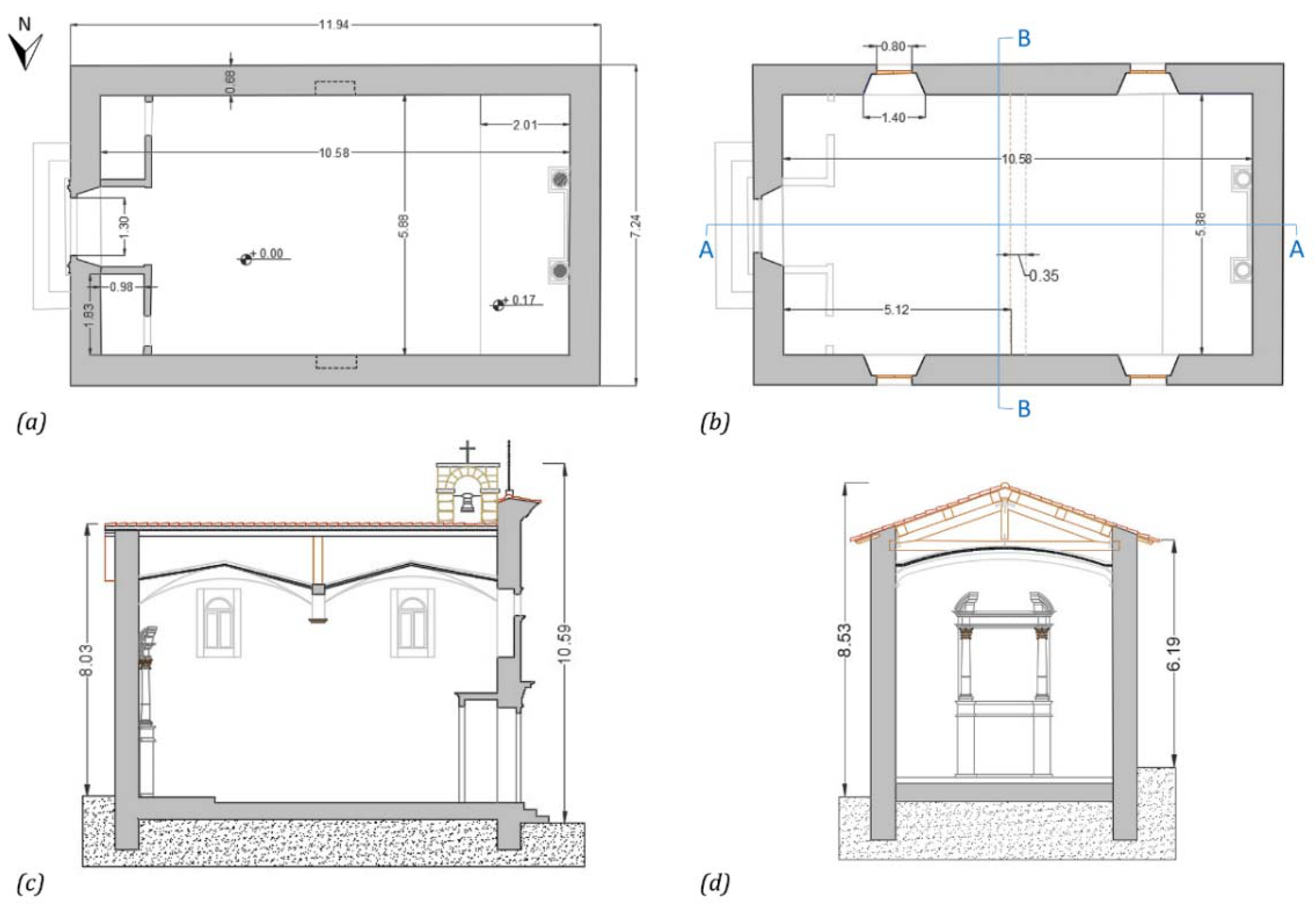
From a geometric point of view, the structure presents a rectangular plan measuring 11.94 m × 7.24 m and it is covered by light vaults in camorcanna, as visible in
Figure 2. The structure reaches a maximum height of 10.59 m in correspondence to the steeple. Two single arched openings are on the lateral sides of the nave and a semicircular opening is located above the portal of the main façade. The bearing masonry structure is characterized by local stone and travertine. The steeple and the curb at the top of the main façade are built with reinforced concrete (see
Figure 3). Finally, the roof is made of chestnut wood.
The church suffered severe damages following the 2016 Central Italy earthquakes, until its closure for safeguard reasons. Indeed, after these events, the church exhibited deep cracks and masonry disaggregation damages on the upper part of the main façade and extended cracks at the connections of the nave walls (see
Figure 4). All the masonry walls introduce the activation of overturning mechanisms.
3. Comparison of Finite and Discrete Element
In this comparative work, the FE and DE advanced modeling were used to analyze the dynamic response of a historical masonry church. The continuous and discontinuous approaches allow explaining the behavior of complex masonry structures investigating different aspects. The FE model represents masonry as a continuum medium through a fictitious and homogeneous isotropic material. For this model, the masonry nonlinear behavior is considered using different constitutive laws in tension and compression smeared in the continuum. Instead, the DE model considers the masonry composed of single distinct units and contacts, i.e., bricks and mortar. In the discrete framework, the masonry nonlinear behavior is concentrated in the contacts between elements, which are regulated by interface laws. Furthermore, the FE leads to the comprehension of the structural global damage, i.e., the in-plane mechanisms of the different walls. Otherwise, the DE allows large displacements and rotations, with the complete detachment and impacts between blocks, considering in-plane and out-of-plane behavior in a unified way.
For this purpose, the nonlinear dynamic analyses are performed by means of the CDP model and the NSCD method respectively for the FE and DE modeling. The CDP permits reproducing the tensile cracking, the compressive crushing, and the degradation of the material under cyclic loads. Otherwise, the NSCD method introduces rigid blocks subjected to sliding by friction and perfect plastic collisions, with a null restitution coefficient.
3.1. Concrete Damage Plasticity Model
To simulate the nonlinear behavior of the masonry, the concrete damage plasticity (CDP) model implemented in the Midas FEA NX© [
21] software was used.
The CDP model developed by Lubliner [
22] and implemented by Lee and Fenves [
23] was initially used for the study of concrete but subsequently proved to be optimal also for simulating fragile materials such as masonry [
8,
20,
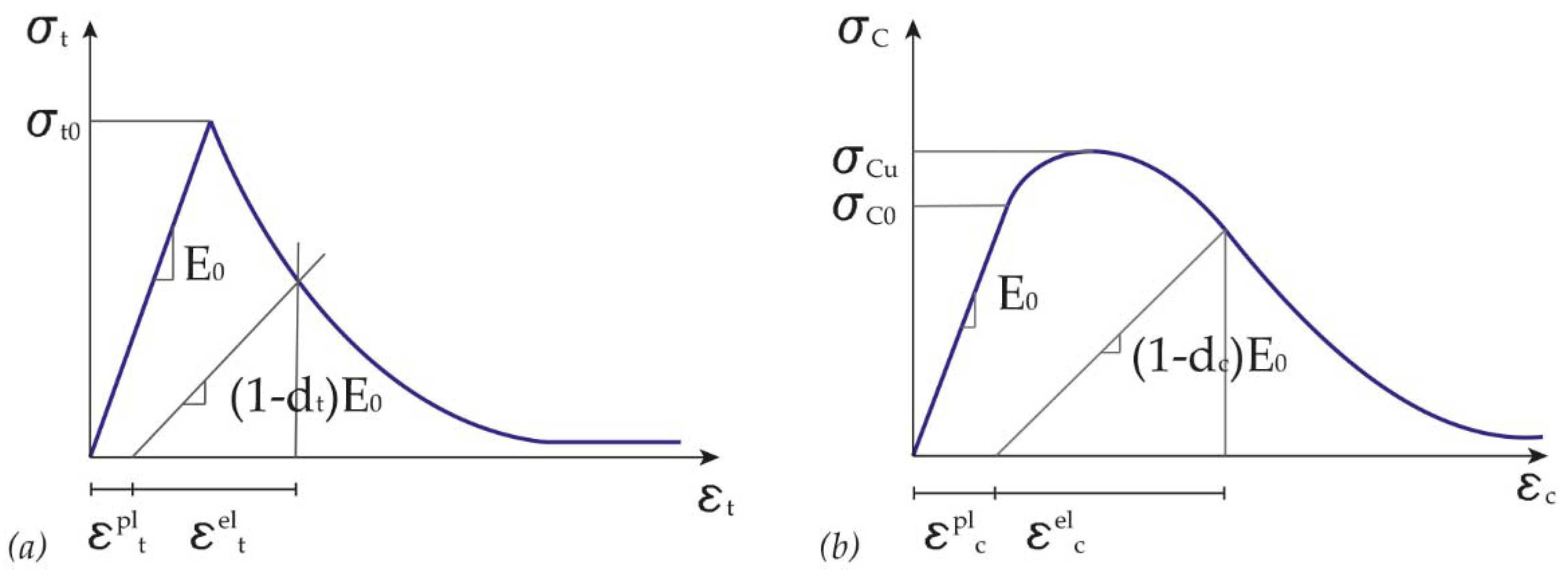
24]. This method allows one to: (i) represent two different types of compression and traction failure, (ii) consider the reduction of the initial elastic modulus,
, due to the plastic deformations,
, and (iii) consider the stiffness recovery following the cracks closure. To represent these phenomena, it is necessary to define two uniaxial stress-strain curves (
Figure 5) and two damage variables respectively to tensile,
, and compression
, using these formulations Equations (1) and (2):
In this model, it is assumed that the masonry obeys a Drucker–Prager resistance criterion with an unassociated flow rule. The surface of this criterion is deformed through a coefficient Kc, to resemble that of Mohr–Coulomb, while the tip of the cone is blunted to avoid numerical convergence problems through an eccentricity parameter.
3.2. Non-Smooth Contact Dynamics Method
The non-smooth contact dynamics method belongs to the discrete element approaches and it was initially developed for the investigation of nonsmoothed granular dynamics. Starting from the mathematical formulation of non-smooth dynamics, the algorithmic developments were introduced by J. J. Moreau [
25] and M. Jean [
26] and then implemented in the LMGC90© [
27], which was used to analyze the church under investigation in this research work. The NSCD method differs from the common DEM for the handling of small length and time scales involved in the dynamics of bodies. In the DEM, pioneered by P. Cundall [
28], the bodies are assumed to be rigid and their contacts obey a viscoelastic behavior with the relative positions and displacements of the bodies corresponding to the local strain variables. The contact interactions concern small time and length scales for the time-stepping schemes involved in the integrals’ resolution of the equations of motion. Instead, in the NSCD the non-smooth dynamics of bodies are evaluated at a large scale than small elastic response times and displacements assuming adequate contact laws. A dynamic system implies a variety of degrees of discontinuity in local or global characteristics, which can be defined as non-smoothness. Considering two bodies, the antagonistic A in interaction with the candidate C, a punctual contact α can be geometrically defined between them. The local frame of the contact is described by normal
and tangential
and
components, conventionally explained with
(see
Figure 6a).
The first interaction law is given by the Signorini’s condition (see
Figure 6b) which defines a complementary relation between the gap g (corresponding to a distance), the normal velocity
, and the normal force
, as following:
As long as the gap remains positive, the normal force is null and thus no force is activated. When the contact occurs, the displacements of the bodies follow the unilateral nature of the contact ensured by the Signorini’s condition.
The second contact condition is defined by the Coulomb’s friction law (see
Figure 6c), which defines a complementary relation between the sliding velocity
, the normal force
and
is the friction coefficient, as in the following system of equation:
In a non-smooth system of rigid bodies, multiple shocks may occur, with the kinetic energy dissipated at very short times as consequence (more details are reported in [
29]). In the system, the energy is dissipated through the contact pulses at the instant time, without viscous damping. In addition, the inelastic collapse involves the restitution coefficient as a null value in the Newton’s law, as explained in [
30].
4. Advanced Numerical Modeling of the Masonry Church
The FE and DE models are created according to the different techniques. For the continuous approach, the structure is discretized with a finite number of 3D tetrahedral elements of 0.4 m average size. Such a model is composed of 23,020 elements, 6283 nodes, and 19,782 degrees of freedom (see
Figure 7a). On the contrary, for the discontinuous approach, the masonry structure is built through an assembly of 3D discrete blocks modeled similarly to the existing masonry texture, slightly simplified since they are regularized including the thickness of the mortar. This complex model is formed by an arrangement of 7636 blocks in order to consider the masonry interlocking (see
Figure 7b).
After the realization of the geometric models, the material parameters and the boundary condition are assigned. The materials survey highlighted that the structure is composed of RC and uncut stone masonry (see
Section 2). The low part of the main façade is characterized by large blocks masonry, as visible in
Figure 4a, thus it assumes higher mechanical proprieties with respect to the other walls of the structure. The masonry parameters for the ancient church analyzed were taken in accordance with the Italian Code [
31,
32] and are shown in
Table 1. In DE, the model is defined by the rigidity assumption and thus described only by the mass density of the masonry. The wooden roof and the camorcanna vaults were not modeled, and the corresponding load was redistributed as additional densities for DE model and masses for FE model on the upper part of the masonry walls in order to ensure the same behavior of the structure.
The masonry nonlinear behavior in the FE model was attributed using the CDP, as explained in
Section 3.1. The CDP model was described by the dilatancy angle, the ratio between biaxial and monoaxial ultimate compressive strength, f
bo/f
co, and the viscosity parameters in addition to the eccentricity and K
c, which define the surface of the failure criterion. The mechanical parameters applied in the CDP model were chosen in accordance with [
33] and are reported in
Table 2. The nonlinear behavior of the masonry was defined by assigning the inelastic monoaxial stress–strain curves in tension and compression shown in
Figure 8. The tensile damage (d
t) range was considered from 0 and 0.9.
The NSCD method (see
Section 3.2) in DE defines the masonry nonlinear behavior at the punctual contacts between the distinct rigid blocks through frictional laws. The mortar and masonry quality depends on the degradation phenomena and on the local materials available. The definition of the corresponding parameters is not a straightforward issue for cultural heritage structures. For the Santissimo Crocifisso Church, the masonry performance and quality are assumed to be quite good for the large uncut stone and worst for the ordinary uncut stone. Considering this, the friction coefficient values were assigned respectively equal to 0.4 and 0.3. However, the contacts at the interface between the blocks of the structure and the foundation were characterized by a friction coefficient value equal to 0.9. Instead, the foundation was considered by fixing all the degrees of freedom of the base nodes in FE model.
In the nonlinear dynamic analyses performed on the church, the FE and DE numerical models were subjected to three-directional seismic actions (north–south, east–west, and vertical) of the three main events that hit Central Italy in the 2016 seismic sequence, as visible in
Figure 1. The stations considered are firstly Amatrice (station AMT in ITACA) and Spelonga (T1244), which are located near Pretare, and then Amatrice (AMT), Campi (CMI), and Forca Canapine (FCC), which are the earthquakes epicenters of 24th August, 26th October and 30th October 2016, respectively.
The comparison between the seismic events is reported in
Table 3, where [
34,
35]:
Rjb is the Joyner-Boore distance, known as the closest point of the site to the surface projection of the fault;
Rrup is the shortest distance between the site and the fault;
Repi is the distance estimated by the geometric swap.
The seismic sequences applied are characterized by a second of initial null values, 10 s of the strong motions, and 5 s of rest among them, as plotted in
Figure 9. The events recorded are applied at the base of the FE and DE models in
Figure 7 in terms of acceleration and velocity, respectively. The velocities were computed by direct integration of the accelerations in a time interval of 41 s, without the use of a correlation method. The time step used in the analyses with both methods was equal to dt = 0.005 s. For the recordings near the church, the corresponding peak ground acceleration (PGA) and velocity (PGV) were equal to −8.51 m/s
2 (PGA-1, t = 3.39 s) and 0.44 m/s (PGV-1, t = 3.33 s), 1.08 m/s
2 (PGA-2, t = 16.64 s) and −0.08 m/s (PGV-2, t = 17.03 s), and −3.47 m/s
2 (PGA-3, t = 34.90 s) and −0.22 m/s (PGV-3, t = 35.07 s), for the first, second, and third events, respectively. For the epicentral recordings, the PGA and PGV were equal to −8.51 m/s
2 (PGA-1, t = 3.39 s) and 0.44 m/s (PGV-1, t = 3.33 s), −6.88 m/s
2 (PGA-4, t = 17.11 s) and 0.44 m/s (PGV-4, t = 17.37 s), and −9.31 m/s
2 (PGA-5, t = 35.22 s) and 0.77 m/s (PGV-5, t = 35.20 s), for the first, second, and third events, respectively.
Analyses in FE model were performed with the full Newton–Rapson solver. Additionally, the Rayleigh damping was specified considering a damping ratio of 5% and the 1st and the 50th mode. Otherwise, the Gauss–Seidel solver was involved in the nonlinear dynamic analyses with DE model and the NSCD requires the use of an implicit time integration scheme. The damping effects, which are essential to the continuum models, were neglected in the NSCD method and the dissipated energy was associated with the contribution of the friction.
5. Critical Discussion of the Results
The main results of the nonlinear dynamic analyses performed with the CDP model and NSCD method were firstly compared under the seismic actions recorded near the church location. The findings aim at investigating the dynamic response and the damages exhibited from the structure during the 2016 Central Italy seismic sequence. Thus, the validation of the models was achieved by combining the numerical damage surveys with the existing crack pattern.
The displacement time histories (THs) in the x, y, and z directions of five church control points calculated by means of the CDP and NSCD methods under the seismic actions near the church are plotted in
Figure 10 and
Figure 11, respectively. The five monitoring points for both numerical models of the church were visible in
Figure 7a,b. Point #1 (P.1) was located in the center of the top of the main (east) façade. Points #2 (P.2) and #3 (P.3) were selected in the center of the top of the lateral walls of the nave, south and north facades, respectively. Point #4 (P.4) was placed in the upper part of the west façade and point #5 (P.5) at the top of the steeple.
The displacement THs in
Figure 10 and
Figure 11 were affected by the PGA and PGV of the first event between seconds 3 and 4, showing a clear nonlinear behavior. During this time interval the church suffered damage, which led to peak x-displacements of −0.02 m and −0.20 m with residual of −0.04 m and −0.06 m for P.1 in CDP and NSCD methods, respectively. Similarly, for P.3 the peak y-displacements were equal to −0.04 m and −0.14 m with a residual of −0.002 m and −0.03 m in CDP and NSCD methods, respectively. The second event in sequence contributes to the cumulated damages without significant effects on the structural behavior, due to the minor intensity recorded at the T1244 station. The third event introduced an increment of the shifts. The peak x-displacements were equal to −0.13 m and 0.16 m for P.1 and P.3 in CDP and NSCD methods, respectively. The peak y-displacements were equal to 0.07 m and 0.17 m for P.2 in CDP and NSCD methods, respectively. The z-displacements did not provide additional information on the damage evolution of the structure for both methods.
In
Figure 12a,b the evolution of the tensile damage in CDP model is reported, implicitly highlighting the areas where the ultimate tensile strength was reached, and displacement in NSCD method for the church analyzed at different time instants. At t = 3.5 s the structure exhibited relevant damages and displacements, which moderately increased during the remaining interval of the seismic sequence. After 11 s, the energies of the subsequent earthquakes were insufficient to activate other cracks, thus just contributing to enlarge the existing crack scenario. Indeed, the tensile damage volume of masonry grew from 22% at the end of the first earthquake to 23.8% at the final step. Concerning the NSCD method, the first major dislocations appeared at 3.5 s and became larger at 41 s, without a complete collapse of the activated masonry mechanisms.
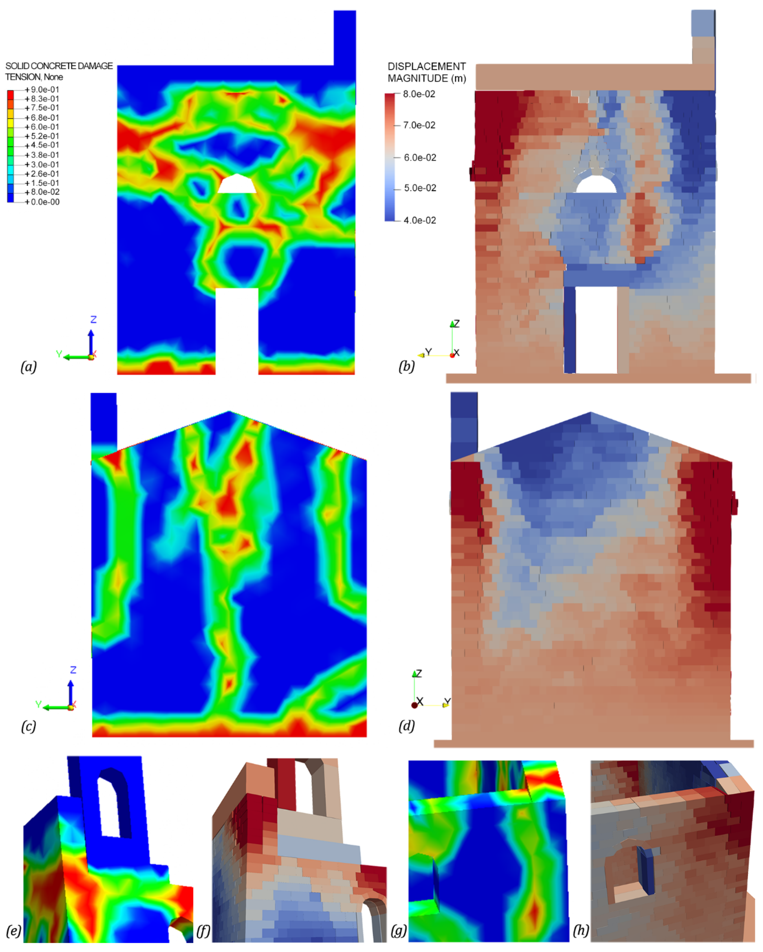
A good match between the numerical damages in
Figure 13 and the existing crack pattern in
Figure 4 was reached. The resultant behaviors explained the relevant applicability of these methods in order to obtain similar failures despite the different laws that govern the two approaches. Both models reproduced the vertical cracks between the semicircular window and the entrance of the main façade (see
Figure 13a,b) and at the connection between the orthogonal walls (see
Figure 13c,d,g,h), and finally presented the activation of the steeple overturning mechanism (see
Figure 13e,f).
Furthermore, the church was subjected to epicentral seismic excitations in order to follow the evolution of the failure mechanism and the main findings were reported in
Figure 14 and
Figure 15. The first event recording was in common with the previous sequence, and thus the structural responses were equal. The second epicentral shock led to an increase in displacements equal to 0.09 m and 0.04 m for P.1 in the x-direction and 0.07 m and 0.03 m for P.2 in the y-direction for CDP and NSCD methods, respectively. The steeple exhibited a total collapse in NSCD method, which corresponded to the large displacements of P.5 at 17 s.
The third strong motion heavily affected the response of the church involving major cumulated shifts. The peak x-displacements were equal to −0.25 m and 0.20 m for P.1 and P.3 in CDP and NSCD methods, respectively. The peak y-displacements were equal to 0.25 m and −0.34 m for P.2 and P.3 in CDP and NSCD methods, respectively. In CDP model the main façade shows large displacement equal to 0.46 m at 41 s, which denotes the activation of the overturning mechanism. In the NSCD method, the dynamics of the church was affected by the friction coefficient values selected for masonry. Indeed, the sliding mechanisms gradually prevailed over the overturning mechanisms, proportionally to the decrease of the friction coefficient value, corresponding to a poor-quality masonry.
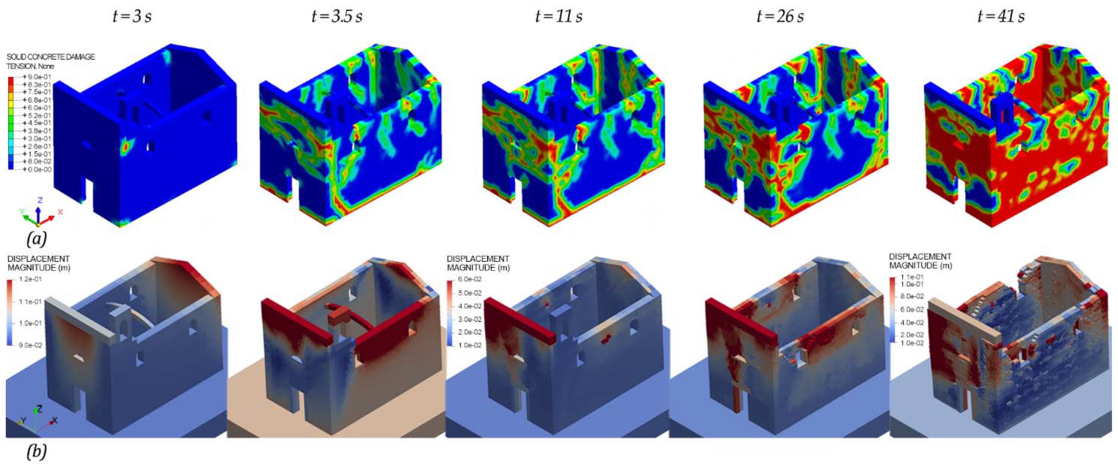
All the three epicentral strong motions caused heavy damages to the church, as visible in
Figure 16. In CDP model the tensile damage volumes of masonry were equal to 22%, 29.4%, and 75.8% at the end of each earthquake, thus underlining that the strong third quake led the structure near to collapse. In NSCD method the activated failure mechanisms were visible in
Figure 16b. In particular, the discrete approach allowed one to predict and capture the local mechanisms as the masonry disaggregation (see at t = 41 s in
Figure 16b), which was neglected in finite element and macro-element approaches.
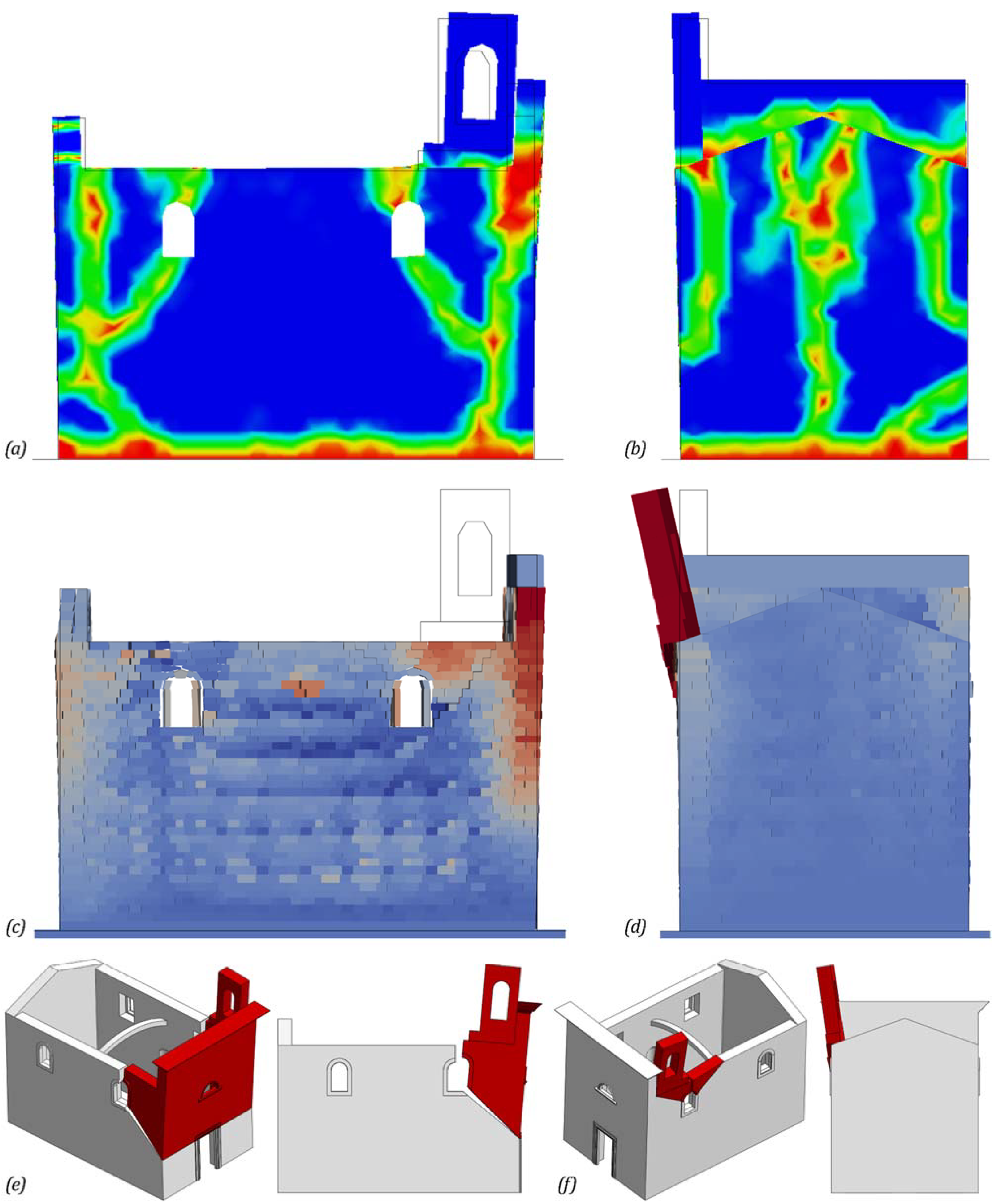
Both FE and DE models allow capturing the activated failure mechanisms from the nonlinear dynamic analyses performed under the epicentral seismic actions. The overturning mechanism of the main façade in
Figure 17e and steeple in
Figure 17f were remarked in the deformed configurations of FE and DE models in
Figure 17a,b and
Figure 17c,d, respectively. Indeed, the damage mechanisms activation is deductible from displacement THs of P.1 and P.5 for both methods. Furthermore, the NSCD method describes the activation and evolution over time of the failure mechanisms, and thus gains a deeper insight into the nonlinear dynamic behavior of the masonry structure.
6. Conclusions
The numerical modeling of the Santissimo Crocifisso Church in Pretare, Arquata del Tronto (AP), was carried out by means of advanced FE and DE models. The relevance of the findings was related to the deep investigation of the masonry nonlinear response. The seismic actions registered near the church lead to the validation of both continuous and discontinuous methods through a good match with real cracks of the structure. The application of the epicentral seismic actions allows obtaining the development of the failure mechanisms with the amplification of the damages. All these numerical results appeared to be interesting in light of the design retrofitting works. Indeed, the complex nonlinear behavior of the church was clearly pointed out with CDP model. Moreover, the NSCD method allowed investigating the local failure mechanisms, as the masonry disaggregation, which is neglected in the finite element and macro-element approaches.
Finally, the comparison of the two methods highlights the important issue concerning the processing time. Indeed, the modeling time was faster in the FE model with respect to the DE model and the computational time for the nonlinear dynamic analyses was expensive for both methods according to the complexity of models. In particular, the analyses of FE and DE models were carried out on server systems characterized by Intel© Core Processor 2.40 GHz with 20 processors (DELL©, USA), and 224 GB of RAM. The computing times of the analyses performed under the seismic actions recorded near the church were approximately equal to 6 and 93 h with CDP and NSCD methods, respectively. The analysis processing times grew under the epicentral recordings as the damages increased, which thus led to 7 and 133 h for CDP and NSCD methods, respectively.


 ,
, 


