Article

On the Relative Kinematics and Control of Dual-Arm Cutting Robots for a Coal Mine

1
School of Mechanical Engineering, Xi’an University of Science and Technology, Xi’an 710000, China
2
Shaanxi Key Laboratory of Mine Electromechanical Equipment Intelligent Monitoring, Xi’an University of Science and Technology, Xi’an 710054, China
*
Author to whom correspondence should be addressed.
Actuators 2024, 13(5), 157; https://doi.org/10.3390/act13050157
Submission received: 5 March 2024 / Revised: 14 April 2024 / Accepted: 22 April 2024 / Published: 24 April 2024
(This article belongs to the Special Issue Advanced Robots: Design, Control and Application—2nd Edition)

Abstract

:
There is an unbalanced problem in the traditional laneway excavation process for coal mining because the laneway excavation and support are at the same position in space but they are separated in time, consequently leading to problems of low efficiency in laneway excavation. To overcome these problems, an advanced dual-arm tunneling robotic system for a coal mine is developed that can achieve the synchronous operation of excavation and the permanent support of laneways to efficiently complete excavation tasks for large-sized cross-section laneways. A dual-arm cutting robot (DACR) has an important influence on the forming quality and excavation efficiency of large-sized cross-section laneways. As a result, the relative kinematics, workspace, and control of dual-arm cutting robots are investigated in this research. First, a relative kinematic model of the DACR is established, and a closed-loop control strategy for the robot is proposed based on the relative kinematics. Second, an associated workspace (AW) for the DACR is presented and generated, which can provide a reference for the cutting trajectory planning of a DACR. Finally, the relative kinematics, closed-loop kinematic controller, and associated workspace generation algorithm are verified through simulation results.

1. Introduction

Coal is the main form of non-renewable energy in the world, and coal mining and laneway excavation are the two main aspects of coal production. However, there is a big gap between the intelligence levels for coal mining and laneway development. Laneway excavation and support are crucial factors affecting the development efficiency of coal mine laneways. The present situation of traditional laneway excavation, to the best of the authors’ knowledge, is that the single-arm tunneling machine is the main equipment [1,2,3] for laneway excavation. The consequence of using the machine above is that in space, laneway excavation and support are in the same position, but they are separated in time, consequently leading to problems of low efficiency in laneway excavation. It is well known that coal mining efficiency far exceeds laneway excavation efficiency, further leading to the unbalanced problem of coal mining and laneway excavation. To overcome these problems, an advanced dual-arm tunneling robotic system for a coal mine is developed in this research. This system can achieve the synchronous operation of excavation and support of laneways to efficiently complete excavation tasks for large-section coal/rock laneways. The major advantage of the proposed dual-arm tunneling robotic system for coal mines is that the laneway excavation and support are separated in space but synchronized in time, consequently shortening laneway excavation time and improving laneway excavation efficiency. In more detail, the proposed dual-arm tunneling robotic system for a coal mine is composed of a dual-arm cutting robot (DACR), a temporary support robot, a drilling and anchoring robot, an electro-hydraulic control platform, a transportation system, and a ventilation and dust removal system.
The proposed DACR uses two cutting arms to efficiently complete excavation tasks for large-section coal/rock laneways. Many challenges arise from advanced dual-arm tunneling robotic systems for coal mines, among which the accurate motion control of the DACR is a crucial issue. Some researchers have discussed kinematics models [4,5,6,7] and control strategies [8,9,10,11,12] for dual-arm robots. Lee et al. [13] transformed the inverse kinematics problem of the robots into a mathematical optimization problem to replace traditional numerical methods, such as the Jacobian matrix. Yang et al. [14] established a special optimization objective function based on the Generalized Relative Jacobian Matrix (GRJM) of dual-arm space robots, which is employed to plan the coordinated motion of two arms. Lei et al. [15] proposed a control algorithm based on the kinematic model of dual-arm robots to prevent arm collisions and introduced a sensitivity index to measure the accuracy of the algorithm. Du and Hu [16] established the kinematic model of a lower limb exoskeleton robot and calculated the angle relationship between the hip and knee joints in the dual-arm structure. In the study, an adaptive controller was also designed to control the motion of the robot, and the effectiveness of the controller was validated through simulation. Ahmed et al. [17] proposed a new analytical quaternion based on the axis vector with the tangent of the rotation angle, which was used to establish the kinematic model of the robot arm. Jiang et al. [18] proposed a combination of geometric and algebraic methods for the calculation of the inverse kinematics of a mine cart robot arm. Wan et al. [19] used Adams to generate the kinematic model of a six-degree-of-freedom intelligent collaborative robot, solved the forward kinematics problem for the robot, and generated the motion trajectory and the limits of motion space for the end-effector based on the proposed kinematic model. Wei [20] established the kinematic model of a four-degree-of-freedom industrial robot based on the Denavit–Hartenberg (D-H) parameter method and solved the pose representation matrix of the robot using the RPY angles. The aforementioned research on robots was conducted based on a common premise, which was that the base of the dual-arm robot was in a fixed state. Compared with the existing literature on dual-arm robots, there is a co-shared movement for the two cutting arms, which will inevitably have an important influence on the movement of the two cutting arms. However, due to the complexity of constraints, the motion of the two cutting arms of a DACR is influenced by the base of the DACR. Existing research on the kinematics, dynamics, and control of dual-arm robots has been presented, but the relative kinematics and control of a proposed DACR with a co-shared movement for the two cutting arms, to the best of the authors’ knowledge, have not yet been investigated. As a result, the motivation behind this research is to investigate the relative kinematics, closed-loop kinematic control strategy, and workspace for a DACR.
It is common knowledge that the workspace of a robot is a 2D or 3D space that the end-effector of the robot can approach with different poses [21,22,23,24,25]. This is an important parameter for designing, controlling, and applying a robot. Wang and Ding [26] proposed a surface enveloping overlay (SEO) algorithm for identifying the workspace of multi-joint serial robots. The algorithm was suitable for analyzing the characteristics of holes in a robot’s workspace. Zeng et al. [27] employed a multi-island genetic algorithm to optimize the workspace of a parallel robot, and they analyzed the factors influencing the volume of the robot’s workspace. Li et al. [28] employed an improved Monte Carlo method to generate clearer boundaries for the dynamic workspace of a multi-robot collaborative towing system. Boanta and Brișan [29] combined robot kinematics with feedforward neural networks to estimate the workspace volume of a robot and solve for the Cartesian coordinates of the robot’s end-effector in a Cartesian space. Xu et al. [30] divided the Monte Carlo algorithm into two stages, namely, subspace generation and subspace expansion, to generate the workspace of a robot. This algorithm addressed the issue of insufficient accuracy in the workspace generated by traditional methods. Determining the workspace of the proposed DACR is more complicated than for traditional single-arm cutting robots because of the complexity of the constraints as well as the co-shared movement for the two cutting arms. The two cutting arms are installed on the same mobile platform, so they cannot be regarded as two single arms that are controlled separately. This makes the workspace of the DACR more complex than that of typical single-arm and dual-arm robots with a fixed base; therefore, a new workspace, the associated workspace (AW) for the DACR, is presented and generated in this research, and it can provide a reference for the cutting trajectory planning of the two cutting arms. To summarize, it can be seen that controlling a DACR has always presented a challenge for dual-arm tunneling robotic systems. Reviewing various scientific literature references, a DACR, to the best of the authors’ knowledge, has not been investigated so far. For this reason, the novelty of this work comes from the following aspects:
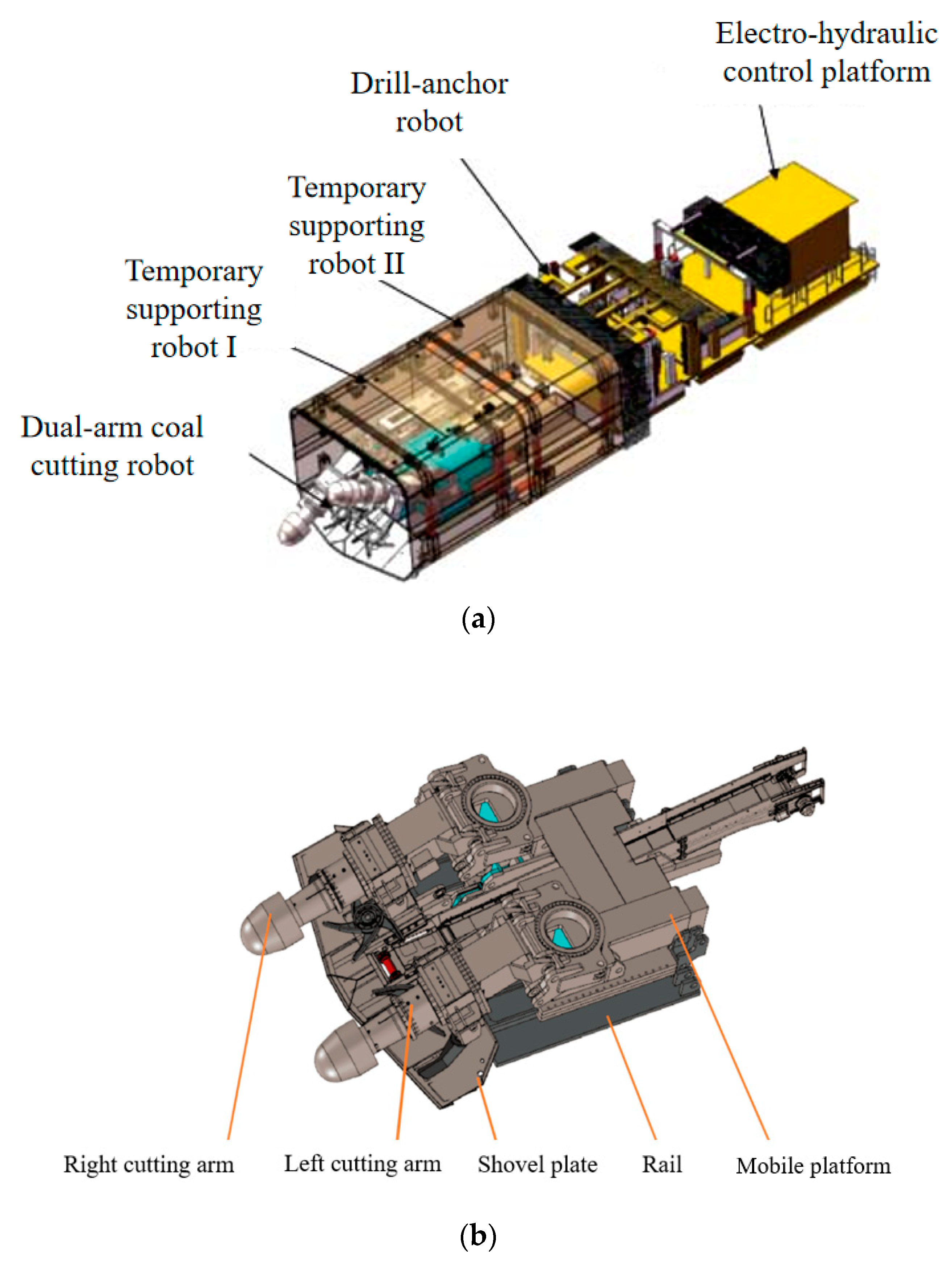
  • An advanced dual-arm tunneling robotic system for coal mines is developed in this research. This system can achieve the synchronous operation of excavation and the permanent support of laneways to efficiently complete excavation tasks for large-section coal/rock laneways.
  • The proposed relative kinematic model of the DACR counteracts the influence of shared motion by integrating the kinematics of both arms into a unified framework. It can simultaneously describe the motion states of the two cutting arms. Additionally, a closed-loop kinematic controller for the robot is developed based on this relative kinematics, enabling control of both cutting arms through a single parameter.
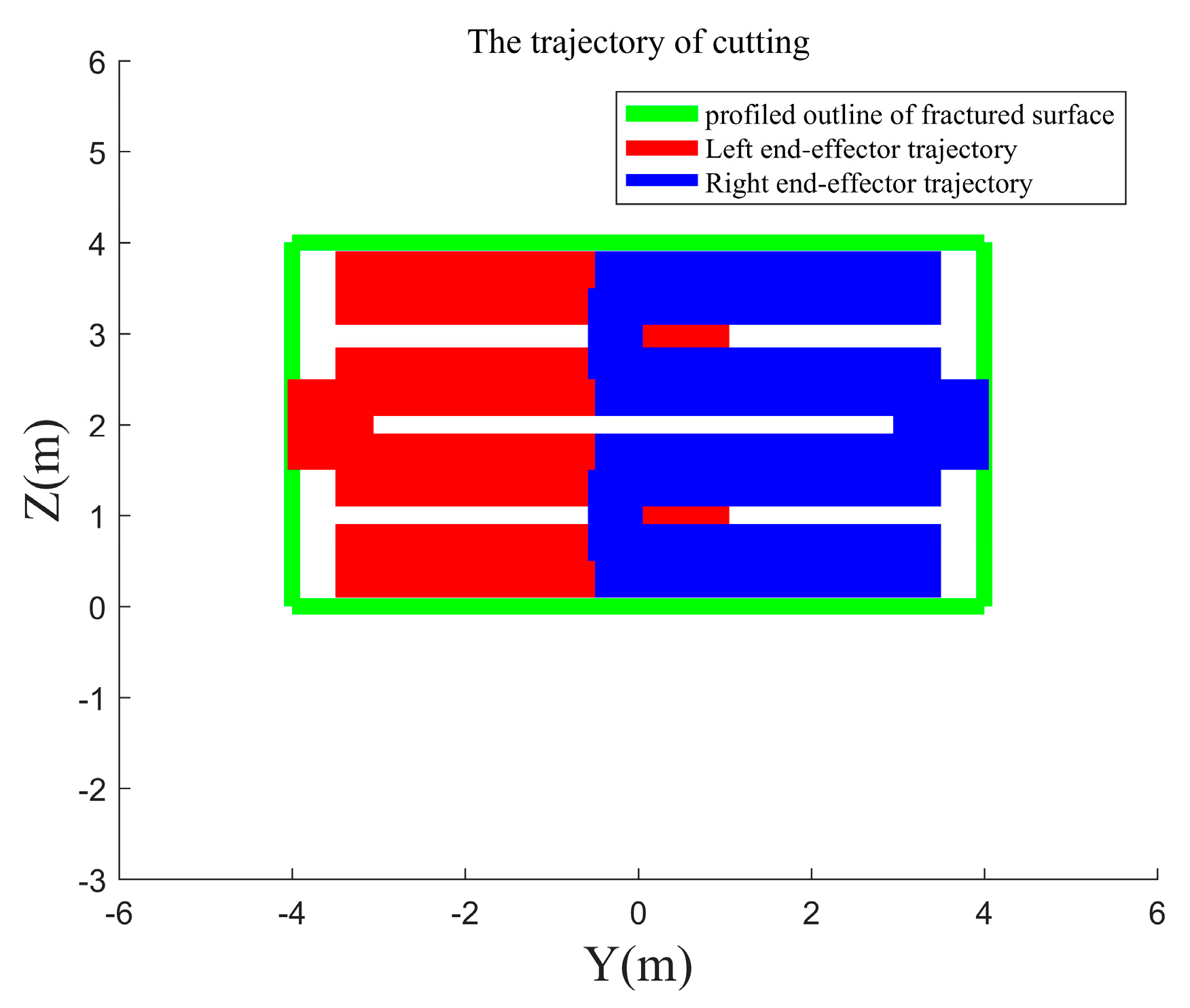
  • The AW for the DACR is presented, and this can provide a reference for cutting trajectory planning of the two cutting arms.
The paper is organized as follows. Section 2 presents the advanced dual-arm tunneling robotic system for a coal mine. In Section 3, the relative kinematic model of the DACR is established, and the AW generation algorithm is presented. In Section 4, a closed-loop kinematic controller for the DACR is proposed based on the relative kinematics. Section 5 delineates the simulation examples and results. The paper concludes with discussion and comments in Section 6.

2. Proposed Dual-Arm Tunneling Robotic System

The proposed dual-arm tunneling robotic system for a coal mine (Figure 1a) is composed of a DACR (Figure 1b), a temporary support robot (I and II), a drilling and anchoring robot, an electro-hydraulic control platform, a transportation system, and a ventilation and dust removal system. As can be seen in Figure 1a, the DACR is installed on the lower shield of the temporary support robot, and it can move forward along the direction of laneway development. When cutting large-sized cross-sections, the movements of the two cutting arms of the DACR are coordinated, and the mobile platform beneath the DACR provides them with a co-shared movement, granting the DACR redundant degrees of freedom, enabling it to move forwards and backwards along the rail direction. The shovel plate beneath the two cutting arms is used to collect the crushed rock. The DACR is employed to complete the task of large-sized cross-section laneway development without moving the body of the robot in the direction perpendicular to the laneway development. This type of robot has a potentially large reachable workspace relative to a traditional single-arm cutting robot. A major challenge in DACR study is the intrinsic mutual influence between the two cutting arms because of the co-shared movement of the robot, which must be addressed simultaneously. The temporary support robot, which includes two identical temporary support shields, is used to support the laneway roof and achieve the progress of the dual-arm tunneling robotic system via the push-and-pull effect between the front and back temporary support shields. Specifically, the back temporary support shield pushes the front shield and the front shield pulls the back shield. The drilling and anchoring robot is used to complete the permanent support of the laneways with a truss bolting technique. The electro-hydraulic control platform supplies power for the dual-arm tunneling robotic system. The transportation system is responsible for transporting the raw coal produced by laneway development to the ground. The ventilation and dust removal system is used to provide fresh air and eliminate dust for the driving face in the coal tunnel.
The proposed dual-arm tunneling robotic system for a coal mine can realize the simultaneous operation of the excavation and permanent support of large-sized cross-section coal/rock laneways, consequently shortening the laneway excavation time and improving the laneway excavation efficiency. However, there are two critical disadvantages in designing and employing the dual-arm tunneling robotic system; one disadvantage is space and the other is complexity. From the perspective of time, the proposed dual-arm tunneling robotic system can significantly shorten the laneway excavation time because of the simultaneous operation of the excavation and permanent support. From the perspective of space, additional space is needed for this system due to the space separation of the excavation and permanent support. With regard to the proposed DACR, because of the co-shared movement for the two cutting arms, the kinematics analysis and control, as has been mentioned above, are much more complex than those for conventional dual-arm robots. For this reason, this issue is considered to be one of the most important aspects in the field of DACRs. An additional challenge for DACRs is the possibility of the two cutting arms colliding with each other, which leads to a constraint in the optimal design and motion control of the robot. The relative kinematics, associated workspace, and control of DACRs are also investigated, as discussed in the next sections.

3. Relative Kinematics of the DACR

As discussed above, there are two critical disadvantages to the control of dual-arm cutting robots. One of the main concerns in modeling and controlling a DACR is dealing with the intrinsic mutual influence between the two cutting arms due to the co-shared movement of the dual-arm cutting robot’s body, which is pivotal to the operation of the entire DACR. The other issue is that the control of the DACR cannot treat the two cutting arms as separate entities, and the two cutting arms require a clear relative positional relationship.
The presented DACR consists of two cutting arms connected to the same mobile platform (Figure 2). Each arm is composed of yaw joint, pitch joint, and prismatic joint. Additionally, the end-effector of each cutting arm is a rotating mechanism used for coal cutting. However, the size of this rotational joint does not affect the relative positions of the end-effectors of the two cutting arms. Therefore, in this research, the rotating mechanism is treated as a point mass. Consequently, each arm of the DACR can be regarded as an arm with three degrees of freedom. The D-H method is commonly used to analyze the kinematic characteristics of the robot and establish the relationship between joint angles and end-effector positions of the two arms in order to determine the transformation relationship between the joint link coordinate systems. As a result, the coordinate system OiXiYiZi is established at the ith joint.

3.1. Relative Kinematics Model of the DACR

D-H parameters are used to describe the kinematic chain of a robotic arm. With this method, every variable represents a specific geometric or angular relationship within the robotic arm. In particular, a denotes the distance from the zi−1 axis to the intersection of the xi and zi−1 axes along the xi axis, and α represents the angle from the zi−1 axis to the zi axis measured about the xi axis. In addition, d represents the distance from the xi−1 axis to the intersection of the xi and zi axes along the zi axis, and q denotes the angle from the xi−1 axis to the xi axis measured about the zi axis. These parameters collectively define the transformation between consecutive links in a serial robot, thus allowing for the computation of the end-effector’s position and orientation based on the joint variables. D-H parameters of the DACR are shown in Table 1. The mobile platform of the DACR provides additional degrees of freedom to both cutting arms simultaneously, with the platform being considered as virtually connected to two yaw joints and the ground coordinate system. Therefore, in Table 1, the parameters q1 and q4 are of equal magnitude but opposite in sign, while the parameters a1 and a4 are equal. The distance L1 between the yaw joint and the axis of the DACR is 1 m, the lengths a5 and a2 between the pitch joint and the yaw joint are both 1 m, and the length variation range of the prismatic joint is the interval [4.08, 4.88].
The homogeneous transformation matrices T 3 0 and T 6 0 for each arm of the DACR are expressed as follows:
T 3 0 = T 1 0 T 2 1 T 3 2 T 6 0 = T 4 0 T 5 4 T 6 5 .
The homogeneous transformation matrix T i i 1 , using the D-H method, can be expressed as follows:
T i i 1 = [ cos q i sin q i cos α i sin q i sin α i a i cos q i sin q i cos q i sin α i cos q i sin α i a i sin q i 0 sin α i cos α i d i 0 0 0 1 ] .
Substituting the D-H parameter into Equation (1), the homogeneous transformation matrices of two arms are calculated as follows:
T 3 0 = [ n x 3 o x 3 a x 3 p x 3 n y 3 o y 3 a y 3 p y 3 n z 3 o z 3 a z 3 p z 3 0 0 0 1 ] ,   T 6 0 = [ n x 6 o x 6 a x 6 p x 6 n y 6 o y 6 a y 6 p y 6 n z 6 o z 6 a z 6 p z 6 0 0 0 1 ] ,
in which
{ n x 3 = cos ( q 1 + q 2 ) cos q 3 n y 3 = sin ( q 1 + q 2 ) cos q 3 n z 3 = sin q 3 { o x 3 = cos ( q 1 + q 2 ) sin q 3 o y 3 = sin ( q 1 + q 2 ) sin q 3 o z 3 = cos q 3 { a x 3 = sin ( q 1 + q 2 ) a y 3 = cos ( q 1 + q 2 ) a z 3 = 0 { p x 3 = a 2 cos ( q 1 + q 2 ) + L 1 cos q 1 + a 3 cos ( q 1 + q 2 ) cos q 3 p y 3 = a 2 sin ( q 1 + q 2 ) + L 1 sin q 1 + a 3 sin ( q 1 + q 2 ) cos q 3 p z 3 = a 3 sin q 3 , { n x 6 = cos ( q 4 + q 5 ) cos q 6 n y 6 = sin ( q 4 + q 5 ) cos q 6 n z 6 = sin q 6 { o x 6 = cos ( q 4 + q 5 ) sin q 6 o y 6 = sin ( q 4 + q 5 ) sin q 6 o z 6 = cos q 6 { a x 6 = sin ( q 4 + q 5 ) a y 6 = cos ( q 4 + q 5 ) a z 6 = 0 { p x 6 = a 5 cos ( q 4 + q 5 ) + L 1 cos q 4 + a 6 cos ( q 4 + q 5 ) cos q 6 p y 6 = a 5 sin ( q 4 + q 5 )   L 1 sin q 4 a 6 sin ( q 4 + q 5 ) cos q 6 p z 6 = a 6 sin q 6 .
Further, utilizing matrices p 3 0 = [ p x 3 p y 3 p z 3 ] T and p 6 0 = [ p x 6 p y 6 p z 6 ] T in Equation (3), the Jacobian matrix for each cutting arm is established as follows:
d p d t = J ( q ) d q d t .
For the DACR, the mobile platform provides a common motion for its dual arms. When the DACR is in operation, the position of the mobile platform must be able to satisfy the positions of both end-effectors simultaneously. This means that the motion of the mobile platform needs to be coordinated simultaneously with the movement of the dual arms, and this results in the kinematics of the two cutting arms being interrelated. Therefore, the dual arms cannot be regarded as two separate robots, but rather require a new kinematic model to integrate the kinematics of both arms together. The DACR may deviate from the expected trajectory because of manufacturing errors and rock hardness, and this can result in collisions between the two cutting arms. It is crucial to have clear and controllable relative position and velocity relationships between the end-effectors of the two cutting arms for the DACR in order to prevent accidents. The relative Jacobian matrix of the DACR is derived to establish the relationship between the relative velocities of the two end-effectors and their joint velocities.
The relationship between the rotation–translation composite transformation from the base to the end-effector of the DACR is established with the following equation:
R 3 0 R 6 3 = R 4 0 R 6 4 p 3 0 + R 3 0 p 6 3 = p 4 0 + R 4 0 p 6 4 ,
in which R i j represents the rotation of coordinate system i with respect to coordinate system j, and p i j represents the position of coordinate system i relative to coordinate system j.
The relative Jacobian matrix for the DACR is obtained by taking the derivative of Equation (5), and this can be expressed as:
J R ( q ) = [ Ψ R Ω 0 3 J L Ω 0 3 J R 1 ] ,
in which Ψ R = [ I S ( p R ) 0 I ] , Ω i j = [ R i j 0 0 R i j ] , I is an identity matrix, JL and JR1 are the Jacobian matrices of the left arm and right arm of the DACR, respectively. S ( p R ) is a skew–symmetric matrix composed of elements from the relative position vectors p 6 3 , used to replace the cross-product operation of vectors. S ( p R ) is expressed in the following form:
S ( p R ) = [ 0 z R y R z R 0 x R y R x R 0 ] .
The relative Jacobian matrix integrates the kinematic models of the two arms together, establishing the mapping relationship between the relative velocities of the two end-effectors and the joint velocities, which can be expressed as:
X ˙ R = J R ( q ) q ˙
in which X ˙ R represents the relative velocity of the two end-effectors, and q ˙ represents the joint velocities of the DACR.
Based on Equation (3), the mapping relationship between the position of the single-arm end-effector of the DACR and the joint angles/lengths can be obtained through forward kinematics, laying the foundation for generating the workspace of the DACR. The size and contour of the DACR’s workspace determine the dimensions of the cross-sections it can cut, ultimately determining the cutting trajectory of the DACR. The relative Jacobian matrix indicates the mapping relationship between the relative velocities of the two end-effectors of the DACR and the joint velocities. Based on the relative Jacobian matrix, a trajectory tracking control algorithm applicable to the cutting trajectories of the DACR can be designed.

3.2. AW Generation Algorithm

The DACR uses the two cutting arms to complete the task of large-sized cross-section laneway development without moving the body of the robot in the direction perpendicular to laneway development. However, for the DACR, the workspaces of the two cutting arms partially overlap, leading to uncertainty about the size of cross-sections that the AW can accommodate. This will affect the motion trajectories of the two cutting arms within the AW, ultimately impacting the control effectiveness. Therefore, it is necessary to investigate the projection of the AW in the forward direction of the DACR, as well as the motion of the two cutting arms in the AW. The Monte Carlo algorithm [31] is a typical method to generate the workspace of a robot, and it is characterized by using a large number of random points to plot the possible positions that the robot’s end-effector can reach in Cartesian space, thereby obtaining the contour of the robot’s workspace. The Monte Carlo algorithm has high computational efficiency, and the number of the robot’s degrees of freedom does not affect the computational error of the Monte Carlo algorithm. As a result, the Monte Carlo algorithm is employed to generate the AW for the DACR. The steps for performing the computation follow:
  • According to the actual size of the DACR, the variable range of the kth joint of the DACR is specified as (qmink, qmaxk).
  • N random values in the interval (0, 1) can be generated by using the function rand(N, 1). The random step size generated by each joint is denoted as q k = q min k + rand ( N , 1 ) ( q max k q min k ) .
  • The end-effectors of the DACR are plotted in Cartesian space at random positions by substituting q k into p 3 0 and p 6 0 in Equation (3). The contour of the AW is generated when the number of random samples N is sufficiently large. It should be noted that the larger the value of N is, the more accurate the depiction of the contour of the AW for the DACR.
The flowchart of the AW generation algorithm for the DACR is shown in Algorithm 1.
Algorithm 1. AW generation algorithm of the DACR.
Actuators 13 00157 i001

4. Proposed Kinematics Controller

The primary objective of controlling most dual-arm robots is to enable them to grasp, manipulate, or lift objects, forming a kinematic closed chain where the relative positions of the end-effectors remain constant. However, for the DACR, during the process of cutting through large-sized cross-sections, the relative positions of the end-effectors change over time. This implies that the scenario where the dual-arm robot forms a kinematic closed chain is merely a special case during the motion of the DACR’s arms. Therefore, for cases where the relative positions of the end-effectors are time-varying, a more general controller needs to be proposed. A closed-loop relative kinematic controller is proposed to control the relative position of the end-effectors for the DACR. The expected relative position and the actual relative position are assumed to be X R d and X R , respectively. Therefore, the relative position error of the two end-effectors can be expressed as follows:
e = X R d X R .
By substituting Equation (7) into the derivative of Equation (8) with respect to time, the expression of the derivative of error e can be expressed as:
e ˙ = X ˙ R d J R ( q ) q ˙ .
The DACR exhibits kinematic redundancy due to the co-shared motion provided by the mobile platform of the DACR to two end-effectors. This implies that the relative Jacobian matrix of the DACR is not a square matrix, and, therefore, the control laws based on relative kinematics for the DACR are designed in the following form:
q ˙ = J R + ( q ) ( X ˙ R d + K 1 e ) + ( I J R + J R ) q ˙ N ,
where K1 is a symmetric positive definite matrix that denotes the gain matrix of the relative position error, and the superscript “+” represents the pseudo-inverse, while q ˙ N represents the kinematic redundancy of the DACR, which means that when the DACR tracks the trajectory, the controller may generate multiple possible movements of the DACR, all of which can satisfy the expected relative velocity X ˙ R d of the end-effectors at this time.
The position-level motion controller based on the relative kinematics model of the DACR is shown in Figure 3, where the feedback loop takes the desired relative position and actual relative position of the two end-effectors as input. By employing Equation (10), the joint velocity vector of the two cutting arms q ˙ can be obtained for any desired relative position of the two cutting arms and the tracking error along the given trajectory converges to zero with a suitable gain K1. Due to the fact that the relative Jacobian matrix is not square, when solving the joint velocity based on Equation (10), multiple sets of solutions may arise, corresponding to the red dashed lines in Figure 3. While these solutions can simultaneously satisfy the relative positions of the two end-effectors and the co-shared motion provided by the mobile platform to the dual arms, they may potentially result in joint angles/lengths exceeding their limits, ultimately leading to singular arm postures. Therefore, it is necessary to simulate the proposed relative kinematic controller.
Substitute the control input q ˙ into Equation (9), then:
K 1 e + e ˙ = 0 .
The choice of K1 can guarantee that the error uniformly converges to zero since K1 is a symmetric positive definite matrix. According to the Lyapunov theorem, the proposed controller, as a result, can stabilize the system, and the relative position error of the two end-effectors for the DACR is ultimately uniformly limited.

5. Simulation Analysis and Discussion

Two working modes are available for the proposed DACR from the viewpoint of practical application. In the first working mode, the co-shared movement of the two cutting arms is usually locked up to reduce the control difficulty and improve the motion accuracy of the two end-effectors for the DACR, which is defined as mode 1 in this paper. In the second working mode, the cutting trajectories of the two cutting arms are generated by the coordinated movement of the body, which is defined as mode 2. With regard to mode 1, the base of the DACR remains stationary, and thus, there is no co-shared movement that affects the movement of the two cutting arms. To reduce the empty distance from the front end of the laneway to the temporary support robot, it is necessary to cooperate with the co-shared movement of the two cutting arms to generate the cutting trajectories of the two cutting arms. With regard to mode 2, the co-shared movement will have a key influence on the movement of the two cutting arms for the DACR. Subsequently, for the above two typical working conditions, the relative kinematic control and AW generation for the DACR are investigated.

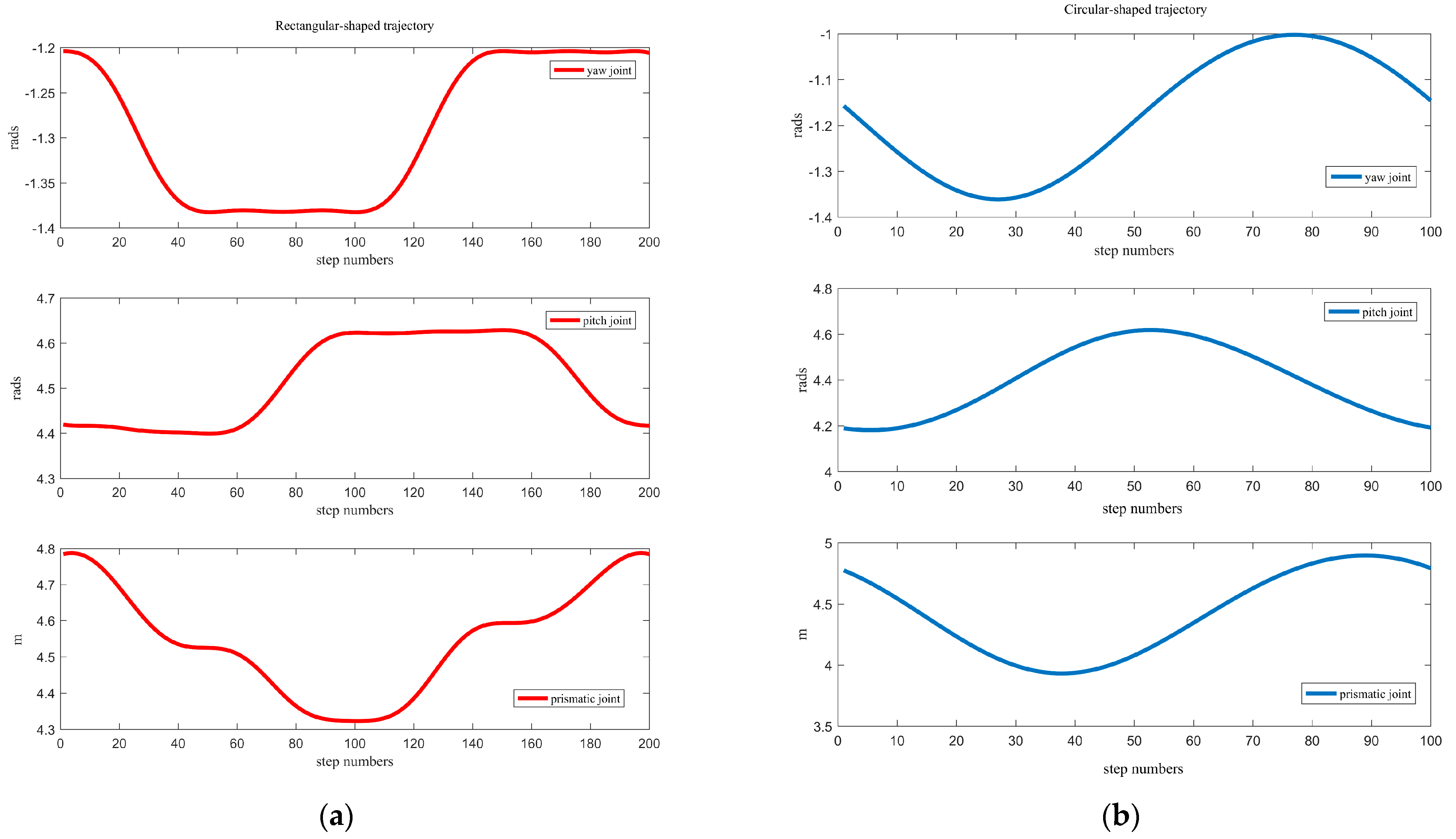
5.1. Motion Continuity of the DACR
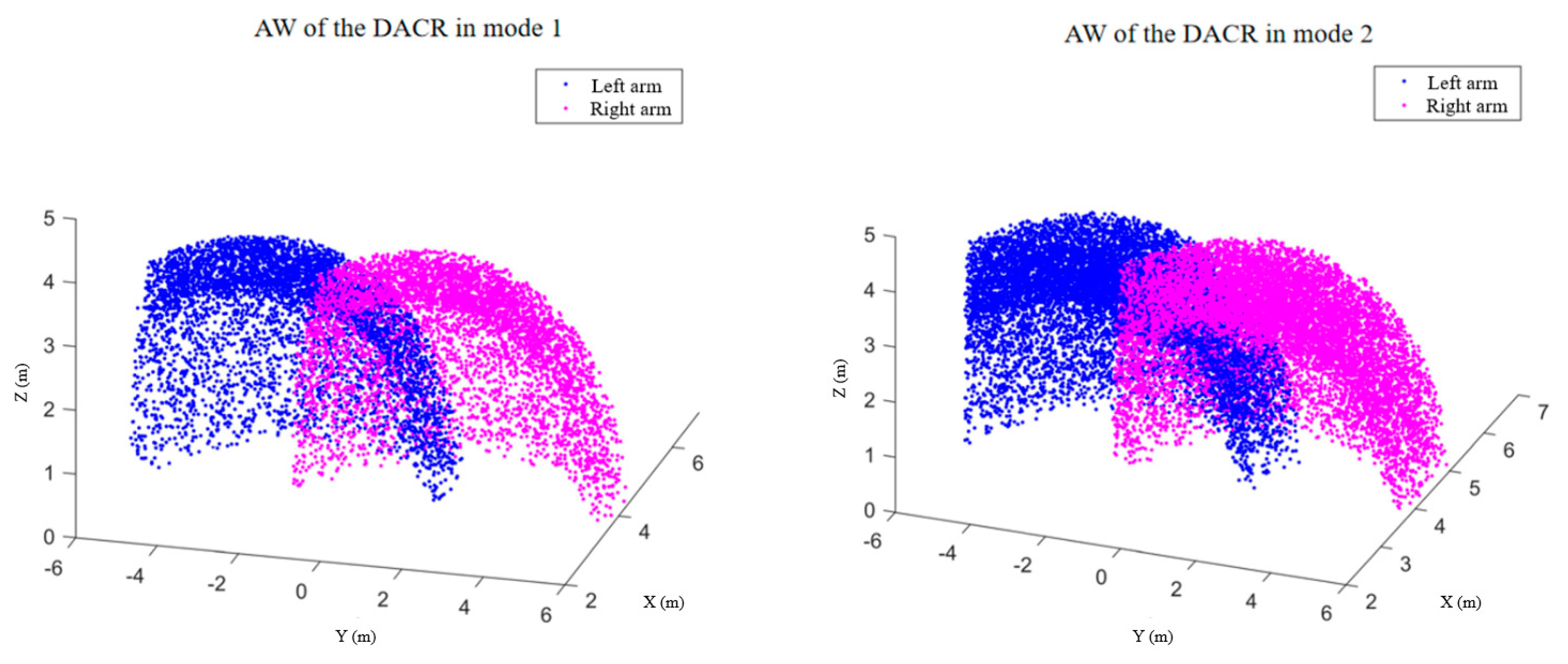
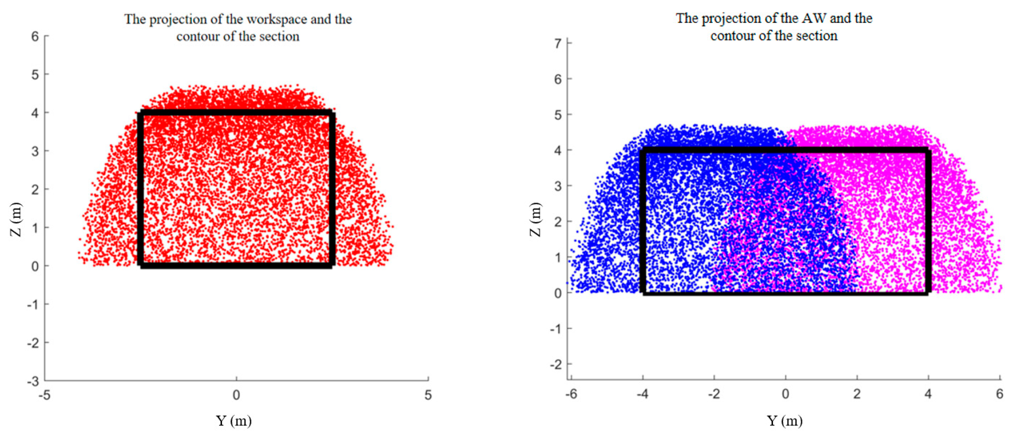
The continuity of robot motion is a measure of whether the robot can function properly and achieve smooth continuous movements [32]. This section describes how a random rectangle and random circle in Cartesian space are generated to verify whether the two cutting arms of DACR can achieve continuous motion. The trajectory of the circle is as follows:
{ x = 5.222 y = 2 + cos ( t ) z = 1.739 + sin ( t ) ,
The expressions for the four sides of the rectangle are as follows:
{ x = 5.222 y = 1 + 2 t z = 2.739 , t [ 0 , 1 ] , { x = 5.222 y = 3 z = 2.739 2 t , t [ 0 , 1 ] , { x = 5.222 y = 3 2 t z = 0.739 , t [ 0 , 1 ] , { x = 5.222 y = 1 z = 0.739 + 2 t , t [ 0 , 1 ] .
To ensure that the co-shared motion of the two cutting arms is unique, the mobile platform is fixed, and in this case, this implies that the variables a1 and a4 are fixed values. The expressions for the positions p 3 0 and p 3 0 of the two end-effectors relative to the base coordinate system in the single-arm kinematic model are known. Based on the analytical method, the changes in joint angles/lengths of the single arm can be solved through the end-effector positions. Therefore, the inverse kinematic model of the single arm can be used to solve the changes in joint angles/lengths corresponding to the end-effector when tracking trajectories. The tracking times for the rectangle trajectory and the circle trajectory are 20 s and 10 s, respectively, with one second divided into 10 steps. The angles/lengths of the joints of the two cutting arms of the DACR, obtained through inverse kinematics, are shown in Figure 4. Figure 4a illustrates the tracking process of the left arm of the DACR for a rectangular-shaped trajectory, while Figure 4b depicts the tracking process of the right arm for a circular-shaped trajectory. The joint parameters of the DACR change continuously and smoothly over time when tracking the continuous trajectories, and there are no sudden changes in the angles or extensions of the DACR’s joints. The results of the inverse kinematics solution indicate that the two cutting arms of the DACR exhibit good motion continuity and do not produce singular poses.
To demonstrate the correctness of the above conclusion, and also to validate the correctness of the single-arm kinematic model, it is necessary to verify the forward kinematic model of the single arm. The model of the DACR is generated in the MATLAB Robotic Toolbox. The two cutting arms of the DACR are considered to be connected at the same rotary joint in the MATLAB Robotic Toolbox due to the base of the DACR being locked. The joint angles/lengths corresponding to each step in Figure 4 are input into the MATLAB Robotic Toolbox for forward kinematic calculation, obtaining the motion animations of the end-effectors of the two cutting arms in Cartesian space, as shown in Figure 5a–d. For the rectangular-shaped trajectory, when the cutting arm is in the states shown in Figure 5a,c, the motion of the end-effector is primarily determined by the yaw joint of the left arm. Therefore, the motion states shown in Figure 5a,c correspond to the angular changes that occur in the yaw joint in Figure 4a. The motion states shown in Figure 5b,d are primarily determined by the pitch joint of the left arm, corresponding to the angular changes of the pitch joint in Figure 4a. For the circular-shaped trajectory, the joint angles/lengths of the cutting arm change uniformly. The simulation shows that the two cutting arms of the DACR do not generate singular postures when tracking the trajectories. This indicates that the DACR has good motion continuity.

5.2. AW of the DACR

For the DACR, there is an overlapping portion in the workspace of the two cutting arms. Therefore, calculating the projection of the AW in the robot’s forward direction can determine whether the DACR’s working range can accommodate large-sized cross-sections, upon which the cutting trajectories of the two cutting arms can be planned. This is a prerequisite for the DACR to simultaneously complete the cutting of large-sized cross-sections and forms the foundation for controlling the DACR. The DACR has two working modes that provide the DACR with two different AWs. With respect to mode 1, the position of the DACR’s base is locked, and the two cutting arms perform the cutting. After completing the cutting work inside the AW, the base moves forward, and the double cutting arms start a new round of cutting. With respect to mode 2, the base maintains a uniform forward progression while the two cutting arms cyclically cut along the trajectory.
In this simulation, the dimensions and operating conditions of the DACR are as follows. The distance from joint 1 to the centerline of the DACR, L1, is one meter. The link lengths a2 and a5 are both one meter. For the DACRs in modes 1 and 2, the yaw angles q2 and q5 are in the intervals [−π/2, 0] and [0, π/2], respectively, while the pitch angles q3 and q6 are both in the interval [0, π/3]. The lengths of prismatic joints 3 and 6, denoted as a3 and a6, are both in the interval [4.08, 4.88], and the random number N is set to 10,000. Further, for working mode 2, the base maintains a uniform forward velocity V set to 0.02 m/s. This results in a1 and a4 being represented as follows:
a 1 ( t ) = a 4 ( t ) = ( V t ) 2 + L 1 2 0.0001411 t 2 + 0.001482 t + 0.993
As shown in Figure 6a,b, the workspace of a single cutting arm of the DACR is generated for working modes 1 and 2, with the workspace in both modes appearing as a spherical shell. It should be noted that the volume of the workspace of the single arm of the DACR in mode 2 is 174.2% larger than in mode 1. The comparison of the workspaces corresponding to the two working modes is shown in Figure 6c. The simulation indicates that the workspace in mode 2 can accommodate laneways with a larger cross-section.
As shown in Figure 7, when the DACR is in working mode 2, which is the continuous mode, the volume of the generated AW is significantly larger than the AW corresponding to working mode 1. This means that in working mode 2, the DACR’s end-effectors are able to reach farther positions in Cartesian space compared to working mode 1. In addition, this implies that in working mode 2, the AW accommodates a larger volume of the rock wall, which allows the DACR to excavate greater depths compared to mode 1.
The projection of the workspaces in the direction perpendicular to the advancement of the DACR is shown in Figure 8, in which the red dots represent the projection of the workspace of the DACR’s single arm, while the blue dots and pink dots denote the projection of the AW formed by the left and right arms. The black contour lines represent the outline of the sections that the DACR can accommodate. For the single cutting arm of the DACR, its workspace can only envelop small-sized cross-section laneways (with a net height not less than 2.5 m and a net width not less than 2.6 m). However, the large-sized cross-section laneways, generally speaking, have a net height greater than 4 m and a net width greater than 5.2 m. This means that a single cutting arm cannot complete the cutting task of large-sized cross-section laneways within one work cycle. However, the DACR with two cutting arms can resolve this issue, enabling the DACR’s AW to fully cover large-sized cross-section laneways. When both cutting arms of the DACR work simultaneously, large-sized cross-section laneways can be cut in one cycle of the DACR. Compared with other dual-arm robots, the two arms of the DACR are kinematically interrelated, and the mobile platform provides a common motion for the two cutting arms. Therefore, the mobile platform simultaneously affects the shape and size of the working space of both cutting arms, making the DACR’s AW more complex compared to the workspace of dual-arm robots with a fixed base, ultimately affecting the trajectory planning of the two end-effectors in the overlapping portion of the AW.
The working procedure of the single cutting arm tunnel boring machine for cutting large-sized cross-section laneways perpendicular to the direction of advance is shown in Figure 9. The red trajectory on the left depicts the first cut of the large section by the single cutting arm tunnel boring machine, and the blue trajectory on the right represents the second cut. The single cutting arm needs to excavate two tunnels when cutting the large-sized cross-section laneway. First, the single-arm tunnel boring machine operates in the left tunnel, cutting along the red trajectory. The space at the rear of the machine is left vacant for support and anchoring. After completing the cutting in the left tunnel, the single-arm tunnel boring machine is paused and moved to the right tunnel, and the second cut begins along the blue trajectory. During the cutting of the large-sized cross-section laneway, the single cutting arm tunnel boring machine alternates between cutting and moving. Although this process is continuous in terms of space, due to the limited workspace of the single cutting arm, it is necessary to alternate work in the two tunnels to complete the cutting of the large-sized cross-section laneway. Therefore, this procedure is discontinuous in terms of time and the workflow is quite cumbersome. Frequent movement of the tunnel boring machine not only increases the workload but also leads to other issues, such as the cross-sectional shapes of the tunnel being inconsistent between the front and rear ends.
The mechanical limits of the two cutting arms are removed in order to ensure that the cutting trajectories of the two end-effectors of the DACR can fully cover the cross-section of the tunnel. The cutting trajectory of the DACR is designed to be a centrally symmetric “S” shape, as shown in Figure 10.
There is a partial overlap in the trajectories of the left and right arms to cut the overlapping rock walls in the AW. The two cutting arms are started asynchronously to ensure that the overlapping portion in the AW is only passed through by one of the two cutting arms during operation. The large rotating cutting mechanism at the end of the two cutting arms fills the gap portion of the cutting trajectory. Compared to mode 1, mode 2 provides a larger AW for the DACR. Therefore, mode 2 is adopted as the main motion mode of the DACR. In mode 2, the trajectories of the two arms of the DACR are divided into seven segments. The cutting trajectory along the X axis of the inertial coordinate system is divided into 100 steps, while the cutting trajectory along the Z axis of the inertial coordinate system is divided into 20 steps, and marks are placed at the starting and ending points of each segment. The DACR joint angles/lengths corresponding to the generated eight endpoints are listed in Table 2. Due to the inflection points of the “S”-shaped trajectory, the direction of joint acceleration at these points undergoes abrupt changes. For DACRs with joints of significant mass, these discontinuities in joint acceleration can affect the dynamics of the joints, causing motor vibrations and impacts, ultimately affecting the operational stability of the DACR. To constrain the accelerations of the joints of the DACR, fifth-order polynomial interpolation is used for trajectory planning for each joint of the DACR, with the constraint that the velocities and accelerations at the inflection points of the joints are zero.
Based on Table 2 and the fifth-order polynomial motion planning of the joints, the trajectories of the two end-effectors of the DACR are shown in Figure 11. The end-effector moves in the direction indicated by the black arrows during cutting, and numbers 1–8 denote the turning points of the trajectory. By reasonably planning the movements of the two cutting arms, the DACR is capable of cutting large-sized cross-sections without collisions, and the DACR does not require moving the mobile platform along a direction perpendicular to the rail. Further, mode 2 of the DACR maintains the movement of the base, enabling the DACR to advance while cyclically cutting. A temporary support robot installed at the rear of the DACR synchronously supports the tunnel during cutting. In comparison to the single cutting arm tunnel boring machine, the DACR, as a dual-arm tunneling robotic system, maintains cyclic and continuous cutting at the front while temporary support robots located at the rear of the DACR immediately support the top of the tunnel after cutting. Subsequently, the drill–anchor robot drives anchors into the tunnel walls to secure the tunnel’s shape. The work of each robot in the dual-arm tunneling robotic system is separated in space but synchronized in time, ultimately expediting the excavation, support, and shaping of large-sized cross-section laneways. This simplifies the “cut–move–cut” workflow of the single cutting arm tunnel boring machine. In addition, the single cutting arm tunnel boring machine may need to excavate two tunnels to complete the cutting of large-sized cross-section laneways, potentially causing non-parallel axes between the two tunnels and leading to dimensional errors in the resulting cross-sections. The base of the DACR provides co-shared movement for its two cutting arms, ensuring that the orientation of the DACR’s AW remains constant in any direction. The dimensions of the resulting cross-sections remain consistent from front to back through reasonable planning of the movements of the two cutting arms.

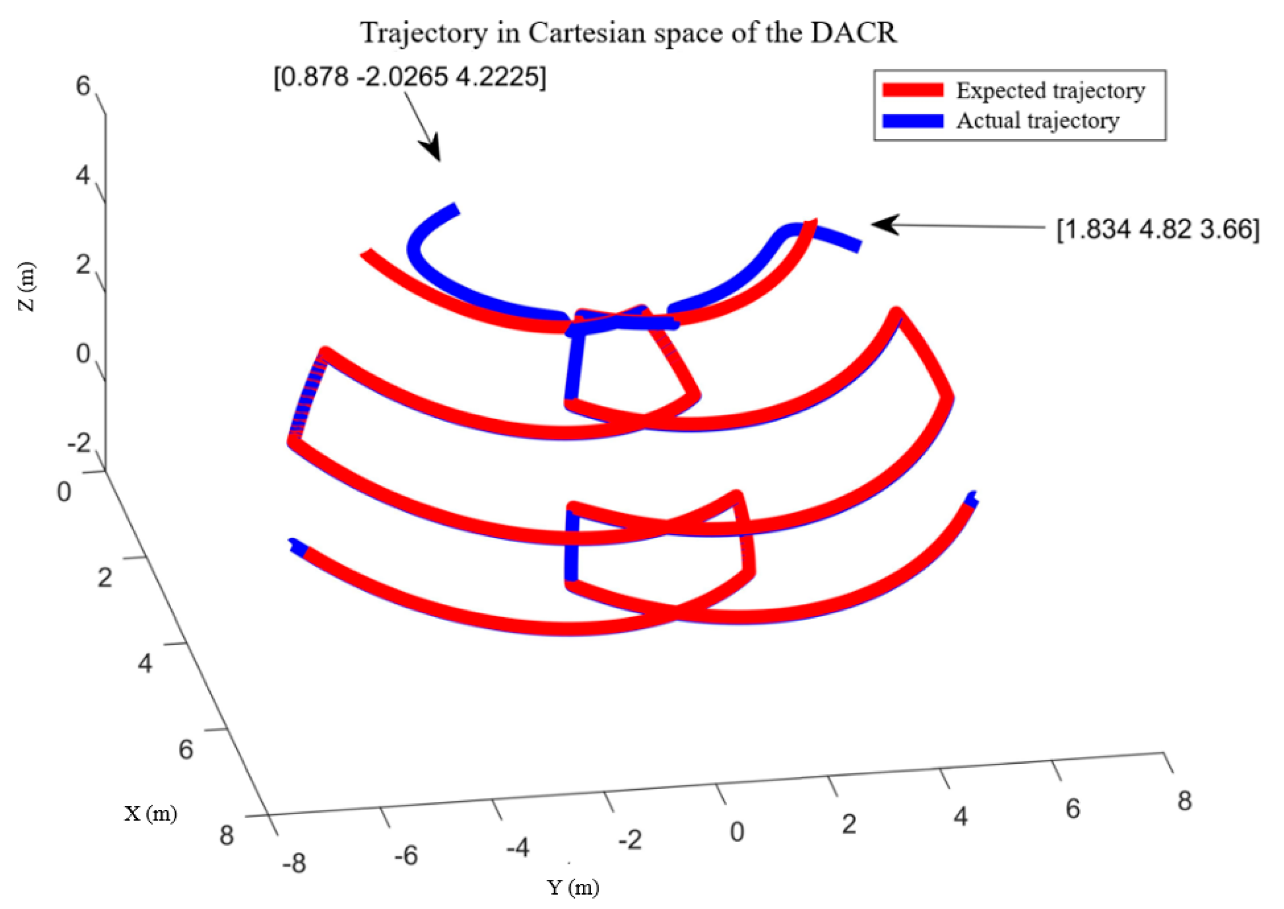
5.3. Trajectory Tracking Control System

To conform to the proposed operational mode 2 of the DACR, the actual motion of the DACR’s mobile platform is assumed to be consistent with the expected motion, maintaining a constant forward motion along the rail, therefore the redundant terms in Equation (10) (i.e., the red dashed line in Figure 3) are removed and only the minimum norm joint velocity solution to the inverse velocity problem is generated. When the DACR is initiated in mode 2, the mobile platform of the DACR is uniformly propelled along the rail, and the two cutting arms of the DACR are both at arbitrary positions in the AW, resulting in the relative positions of the two end-effectors of the DACR being random. Therefore, the positions of the two end-effectors of the DACR in Cartesian space are assumed to be [0.878 −2.0265 4.2225]T and [1.834 4.82 3.66]T, and the two cutting arms of the DACR are set to start simultaneously. These values are substituted into matrix p 6 3 in Equation (5) to represent the initial relative positions of the two end-effectors of the DACR, yielding the vector p 6 3 as [4 3 −2.9]T, which is used to indicate the initial relative positions of the DACR’s two end-effectors. At the start of the DACR, the two end-effectors are treated as two particles with a zero relative rotational angle. Hence, the value of p R 0 is as follows:
p R 0 = [ p 6 3 φ 6 3 ] = [ 4 3 2.9 0 0 0 ] T .
The gain matrix K1 is diag [0.08 0.068 0.083 0.07 0.065 0.08], and the tracking time for X R d is 47 s, with 1 s divided into 10 steps. The relative kinematic controller produces a unique solution because the movement of the DACR’s mobile platform in mode 2 is deterministic, and the actual motion of the mobile platform is assumed to be consistent with the expected motion, with the movement speed of the DACR’s mobile platform locked at 0.02 m per second. Due to the mapping relationship between the forward pushing movement of the mobile platform and q1 in Table 1, the motion of the mobile platform can be represented by q ˙ 1 , as shown in Figure 12a. It can be determined from Figure 12b–g that the controlled joint velocities, with the action of the controller based on the relative Jacobian matrix, eventually exhibited regular changes within 100 steps. Figure 12b–g indicate that within 100 steps, there were abrupt changes in the pitch and prismatic joint velocities of the DACR. This is because by this time, both yaw joints have already achieved trajectory tracking, while there were still errors in the angles and lengths of the pitch and prismatic joints. At this stage, the controller only acted on the pitch and prismatic joints, resulting in abrupt changes in their velocities.
The two cutting arms of the DACR are required to start from a stationary state and cut the rock wall along the red and blue trajectories in Figure 11. The actual motion of the DACR’s mobile platform matches the expected motion, both locked to move uniformly forward, and the mapping relationship between q1 in Table 1 and the forward motion of the mobile platform can be represented by q1 as shown in Figure 13a, which causes the relative kinematic controller to generate only the minimum norm solution for joint velocities, thus resulting in matrix ( I J R + J R ) q ˙ N being a zero matrix in Equation (10) at this time. From Figure 13b–g, it can be seen that when the two cutting arms of the DACR track the S-shaped trajectory, the variations in joint angles/lengths are continuous and smooth, further demonstrating the continuity of the DACR’s motion. The angle/length variations of the joints in the DACR’s two arms are shown in Figure 13b–g, where the blue lines (i.e., the expected values) come from the joint angle/length variations of the DACR as shown in Table 2. Figure 13b,c represent the yaw joint angles of the DACR’s two arms, Figure 13d,e show the pitch joint angles, and Figure 13f,g display the length variations of the prismatic joints in the DACR’s two arms. It can be observed from Figure 13b–g that the angle/length variations of the DACR’s two arms converge to the desired values within 100 steps, thus indicating the effectiveness of the relative kinematic controller. It should be noted that the desired motions of the DACR’s two arms are asynchronous, which causes the expected value of the yaw joint angle of the DACR’s right arm to remain constant for some time after the simulation begins, while the two arms of the DACR in the simulation are started synchronously. This indicates that the two arms of the DACR are effectively controlled to approach the motion state when working asynchronously.
With the action of the relative kinematic controller, after the synchronous start of the two cutting arms, the X R generated by the two end-effectors gradually approaches the expected values, as shown in Figure 14, where the blue lines (i.e., the expected relative positions) are calculated by substituting the parameters shown in Table 2 into the forward relative kinematics model (i.e., p 6 3 in Equation (5)). The positions of the two end-effectors are controlled to the expected values within 100 steps.
As shown in Figure 15, the errors along the X, Y, and Z axes converge to zero within 100 steps. It can be observed from the figure that the relative kinematic controller can adjust the two cutting arms of the DACR with a synchronous start of the two cutting arms to follow the motion pattern of asynchronous operation. The controller shows good performance in reducing errors with a fast feedback velocity.
The control effect of the relative kinematic controller is shown in Figure 16, where the blue and red trajectories represent the actual positions and expected positions of the two end-effectors of the DACR in Cartesian space, respectively. With correction from the controller, the end-effectors of the left and right cutting arms gradually approach the desired red trajectory and eventually remain close to the desired S-shaped trajectory. Because the dual arms of the DACR work asynchronously, after stably tracking the desired trajectory, the two end-effectors of the DACR pass through the overlapping section of the AW one after another.
The absolute error is defined as the two-norm of the difference between the relative position vectors of the two end-effectors of the DACR after tracking the desired trajectory stabilizes and the expected relative position vector. The absolute error of the relative position of the DACR’s end-effectors can be obtained as follows:
e = X R max X R d = 0.01837   m .
The root mean square error (RMSE) is a statistical measure of the difference between observed values and expected values. In this simulation, the RMSE is defined as follows. After the expected trajectory tracking stabilizes, the angle/length error of each joint at each step by the DACR is calculated. This results in each joint generating N errors in angle/length. Compute the sum of squares of errors for each joint, take the average, and, finally, calculate the square root to obtain the root mean square error for each joint. The expression for the RMSE is as follows:
R M S E = 1 N i = 1 N ( q d q ) 2
The RMSE for each joint of the DACR is shown in Table 3.
The simulation results and error calculations for the controller indicate that tracking of the expected relative positions is effective, and the tracking performance of the angles/lengths of each joint under control is good. Solely from the perspective of simulation results, the controller is capable of effectively controlling the motion of the DACR’s dual arms using only the relative position as the unique variable. However, this research only focuses on the kinematic control of the DACR and does not consider other factors that may affect its control effectiveness, such as vibrations generated during coal cutting, dynamic characteristics of the system, and the stiffness of each joint. Therefore, establishing a more precise model and conducting experiments on the DACR are the future research directions for enhancing its control effectiveness.

6. Conclusions

DACRs are one of the most significant concerns for proposed dual-arm tunneling robotic systems because DACRs have an important influence on the forming quality and excavation efficiency of large-sized cross-section laneways. However, the critical issues related to DACRs have not been reported, so the goal of this work is to address the main issues related to the presented DACR. The following conclusions can be drawn:
  • An advanced dual-arm tunneling robotic system for a coal mine is developed, and the main components and characteristics of the robotic system are presented in this paper. The major benefit of this type of robotic system is the achievement of the synchronous operation of excavation and permanent support of laneways.
  • The relative kinematic model of the DACR is established. This model integrates the independent kinematics of both arms into a unified framework, allowing the simultaneous description of the motion states of both arms using only one variable. Additionally, a control strategy is proposed based on relative kinematics, enabling simultaneous control of both cutting arms by using a single variable. Furthermore, the AW of the DACR is generated and proposed by a Monte Carlo algorithm.
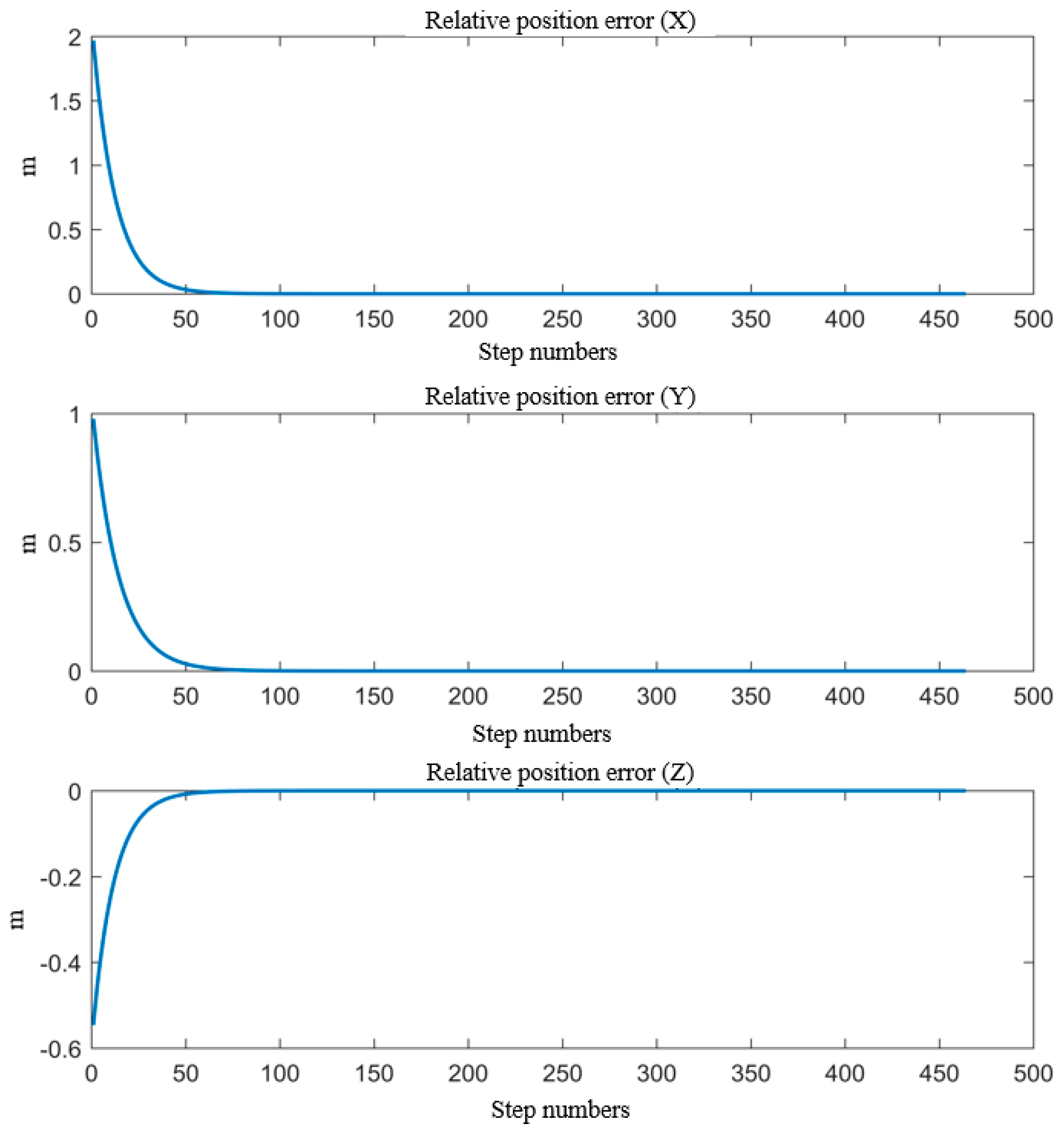
  • The simulation of the motion continuity of the DACR validates the correctness of its relative kinematics model. The status of the DACR is studied for two typical working modes, and the simulation of the AW verifies that the DACR has a larger workspace and reduces the excavation process of large-sized cross-section laneways, thereby improving mining efficiency. Finally, the simulation of relative kinematic control selects the more suitable mode 2 and demonstrates the effectiveness of the proposed control strategy. The DACR converges to the desired trajectory within 50 steps, with an absolute error in the relative positions between the two arms and the desired relative positions of less than 0.01837 m, and the root mean square error of the angle/length of each joint is maintained at a small value. This indicates that the DACR can achieve precise feedback control with good error correction effect and response speed, with minimal fluctuations after trajectory tracking stabilization. This provides a theoretical foundation for the design, analysis, and future implementation of dynamic control for the proposed DACR.
  • Compared to other dual-arm robots, the advantage of the DACR’s control strategy lies in the proposed relative position controller’s ability to track changes in the relative positions of the end-effectors. In contrast, conventional dual-arm robots primarily focus on operations such as transporting, gripping, and lifting objects, where the relative positions of the two end-effectors remain constant. Therefore, the proposed controller exhibits greater versatility and can serve as a reference for future dual-arm robot control systems.
There are some intrinsic limitations of the advanced dual-arm tunneling robotic system for a coal mine and the DACR in this work. Firstly, the proposed controller can simultaneously control the motion of both arms by using a single variable (i.e., the relative position of the dual-arm end-effectors). However, the controller may yield multiple sets of feasible solutions. These solutions can satisfy both the expected motion of both arms and the co-shared motion induced by the mobile platform, but they cannot guarantee that the angles/lengths of other joints remain within specified ranges, ultimately leading to singular arm poses. This research only considers solutions under the condition of deterministic motion of the mobile platform. Therefore, further research is needed to address the issues of the controller yielding multiple solutions and avoiding singular arm poses. Secondly, the effects of the relative dynamics of the DACR on the trajectory tracking accuracy of the two cutting arms, which are of great importance and challenging, still need to be investigated in detail. The consideration of the relative dynamics of the DACR is a topic for further research. Therefore, in the future, an experimental platform will be established to validate the proposed relative kinematic model and controller of the DACR. Additionally, there will be an in-depth investigation into the dynamic model of the DACR, particularly focusing on the relationship between the output force of the DACR and the joint force, which is crucial for the DACR’s ability to cut rock walls. Finally, other control algorithms based on the dynamic model of the DACR will be proposed, and the effectiveness of the DACR’s dynamic controller will be verified through experiments.

Author Contributions

Conceptualization, P.L. and H.Z.; methodology, P.L.; software, H.Z. and Y.Z.; validation, P.L. and H.Z.; formal analysis, H.Z.; investigation, H.Z.; resources, Y.Z.; data curation, H.Z.; writing—original draft preparation, P.L.; writing—review and editing, P.L. and X.Q. All authors have read and agreed to the published version of the manuscript.

Funding

The authors gratefully acknowledge the financial support of Shaanxi Province Natural Science Basic Research Program Project under Grant No. 2024JC-YBMS-324, Education Department of Shaanxi Provincial Government Service Local Special Project under Grant No. 23JC053, and Bilin District Applied Technology Research and Development Projects in 2022 under Grant No. GX2228.

Data Availability Statement

The datasets used and analyzed during the current study are not available for public disclosure and are available from the corresponding authors upon reasonable request.

Acknowledgments

The authors would like to thank the support from Open Fund of Key Laboratory of Electronic Equipment Structure Design (Ministry of Education) at Xidian University.

Conflicts of Interest

The authors declare no conflicts of interest.

References

  1. Tang, Y.; Tang, J.; Wang, S.; Wang, S. Analysis of rock cuttability based on excavation parameters of TBM. J. Geomech. Geophys. Geo-Energy Geo-Resour. 2023, 9, 93. [Google Scholar] [CrossRef]
  2. Zheng, Y.; He, L. TBM tunneling in extremely hard and abrasive rocks: Problems, solutions and assisting methods. J. Cent. South Univ. 2021, 28, 454–480. [Google Scholar] [CrossRef]
  3. Zhang, X.; Zheng, X.; Yang, W.; Li, Y.; Ma, B.; Dong, Z.; Chen, X. Research on path planning method of underground mining robot. J. Coal Geol. Explor. 2024, 52, 1–13. [Google Scholar] [CrossRef]
  4. Zhang, Y.; Huang, Q.; Liao, Q.; Yang, X.; Wei, S. Research on the novel method for inverse kinematics analysis of spatial 6R serial manipulators. J. Mech. Eng. 2022, 58, 1–11. [Google Scholar] [CrossRef]
  5. Vavro, J.; Vavro, J.; Marček, L.; Taraba, M.; Klimek, L. Kinematic and dynamic analysis and distribution of stress for six-item mechanism by means of the SolidWorks program. IOP Conf. Ser. Mater. Sci. Eng. 2021, 1199, 012047. [Google Scholar] [CrossRef]
  6. Kheylo, S.V.; Garin, O.A.; Terekhova, A.N.; Prokhorovich, V.E.; Dukhov, A.V. Solving problems of the dynamics of a manipulator with six degrees of freedom. J. Mach. Manuf. Reliab. 2022, 51, 30–36. [Google Scholar] [CrossRef]
  7. Sun, X.; Wang, H.; Guo, X.; He, X. Kinematics study on redundant manipulator with serial-parallel hybrid mechanism of bolter-drilling rig. Mech. Sci. Technol. Aerosp. Eng. 2023, 42, 493–503. [Google Scholar] [CrossRef]
  8. Wang, X.; Shi, L.; Katupitiya, J. Robust control of a dual-arm space robot for in-orbit screw-driving operation. Acta Astronaut. 2022, 200, 139–148. [Google Scholar] [CrossRef]
  9. Ouyang, Y.; Sun, C.; Dong, L. Actor–critic learning based coordinated control for a dual-arm robot with prescribed performance and unknown backlash-like hysteresis. ISA Trans. 2022, 126, 1–13. [Google Scholar] [CrossRef]
  10. Shen, Y.; Fan, G.; Tang, X.; Dong, Y.; Deng, L. Gaussian process based differential kinematics control of the soft robot. Control Eng. China 2021, 28, 1360–1365. [Google Scholar] [CrossRef]
  11. Guo, J.; Liu, J. Workspace analysis and structure optimization of parallel robot. Manuf. Technol. Mach. Tool 2022, 11, 20–26. [Google Scholar] [CrossRef]
  12. Wang, J.; Xu, J. Kinematic modeling and simulation of dual-arm robot. J. Robot. Netw. Artif. Life 2021, 8, 56–59. [Google Scholar] [CrossRef]
  13. Lee, S.H.; Lee, Y.J.; Kim, D.H. Extension of inverse kinematic solution for a robot to cope with joint angle constraints. Int. J. Control Autom. Syst. 2023, 21, 1899–1909. [Google Scholar] [CrossRef]
  14. Yang, S.; Wen, H.; Hu, Y.; Jin, D. Coordinated motion control of a dual-arm space robot for assembling modular parts. Acta Astronaut. 2020, 177, 627–638. [Google Scholar] [CrossRef]
  15. Lei, M.; Wang, T.; Yao, C.; Liu, H.; Wang, Z.; Deng, Y. Real-time kinematics-based self-collision avoidance algorithm for dual-arm robots. Appl. Sci. 2020, 10, 5893. [Google Scholar] [CrossRef]
  16. Du, H.; Hu, N. Kinematics and dynamics analysis of lower limb robot based on human motion data. J. Mech. Transm. 2022, 46, 128–134. [Google Scholar] [CrossRef]
  17. Ahmed, A.; Ju, H.; Yang, Y.; Xu, H. An improved unit quaternion for attitude alignment and inverse kinematic solution of the robot arm wrist. Machines 2023, 11, 669. [Google Scholar] [CrossRef]
  18. Jiang, Z.; Yu, Z.; Zhang, X. Research on the inverse kinematic algorithm of the robot arm of the minecart. J. Phys. Conf. Ser. 2023, 2483, 012012. [Google Scholar] [CrossRef]
  19. Wan, Y.; Li, H.; Chen, X. Kinematics analysis and visualization simulation of 6-DOF intelligent cooperative robot. J. Phys. Conf. Ser. 2022, 2283, 012013. [Google Scholar] [CrossRef]
  20. Wei, Y. Kinematics analysis and modelling based on 4 DOF industrial robot. J. Phys. Conf. Ser. 2023, 2562, 012076. [Google Scholar] [CrossRef]
  21. Meng, Z.; Cao, W.; Ding, H.; Chen, Z. A new six degree-of-freedom parallel robot with three limbs for high-speed operations. Mech. Mach. Theory 2022, 173, 104875. [Google Scholar] [CrossRef]
  22. Huang, Y.; Li, Z.; Xing, K.; Gong, H. A manipulator size optimization method based on dexterous workspace volume. Cobot 2022, 1, 3. [Google Scholar] [CrossRef]
  23. Bader, A.M.; Maciejewski, A.A. The kinematic design of redundant robots for maximizing failure-tolerant workspace size. Mech. Mach. Theory 2022, 173, 104850. [Google Scholar] [CrossRef]
  24. Meng, Q.; Fei, C.; Jiao, Z.; Xie, Q.; Dai, Y.; Fan, Y.; Shen, Z.; Yu, H. Design and kinematical performance analysis of the 7-DOF upper-limb exoskeleton toward improving human-robot interface in active and passive movement training. Technol. Health Care 2022, 30, 1167–1182. [Google Scholar] [CrossRef]
  25. Liu, C.; Gao, B.; Yu, C.; Tapus, A. Self-protective motion planning for mobile manipulators in a dynamic door-closing workspace. Ind. Rob. 2021, 48, 803–811. [Google Scholar] [CrossRef]
  26. Wang, X.-Y.; Ding, Y.-M. Method for workspace calculation of 6R serial manipulator based on surface enveloping and overlaying. J. Shanghai Jiaotong Univ. Sci. 2010, 15, 556–562. [Google Scholar] [CrossRef]
  27. Zeng, Q.; Zhou, G.; Shi, J.; Li, Y.; Liu, Y.; Chen, T.; Wang, L. Robot workspace optimization based on Monte Carlo method and multi island genetic algorithm. Mechanics 2022, 28, 308–316. [Google Scholar] [CrossRef]
  28. Li, J.; Zhao, Z.; Zhang, S.; Su, C. Dynamics and workspace analysis of a multi-robot collaborative towing system with floating base. J. Mech. Sci. Technol. 2021, 35, 4727–4735. [Google Scholar] [CrossRef]
  29. Boanta, C.; Brișan, C. Estimation of the kinematics and workspace of a robot using artificial neural networks. Sensors 2022, 22, 8356. [Google Scholar] [CrossRef]
  30. Xu, Z.; Zhao, Z.; He, S.; He, J.; Wu, Q. Improvement of Monte Carlo method for robot workspace solution and volume calculation. Opt. Precis. Eng. 2018, 26, 2703–2713. [Google Scholar] [CrossRef]
  31. Su, C.; Li, J.; Ding, W.; Zhao, Z. Static workspace analysis of a multi-robot collaborative towing system with floating base. Int. J. Model. Simul. Sci. Comput. 2021, 12, 2150009. [Google Scholar] [CrossRef]
  32. Li, T.; Jia, Q.; Chen, G.; Sun, H. Motion reliability assessment of robot for trajectory tracking task. Syst. Eng. Electron. 2014, 36, 2556–2561. [Google Scholar] [CrossRef]
Figure 1. The dual-arm tunneling robotic system and dual-arm coal cutting robot. (a) The dual-arm tunneling robotic system; (b) The dual-arm coal cutting robot.
Actuators 13 00157 g001
Figure 2. Dual-arm cutting robot structure.
Actuators 13 00157 g002
Figure 3. Controller based on relative position error. DACR, dual-arm cutting robot.
Actuators 13 00157 g003
Figure 4. Changes in the angles/lengths of the joints when the DACR is tracking continuous trajectories.
Actuators 13 00157 g004
Figure 5. The motion of the two end-effectors of the DACR in Cartesian space.
Actuators 13 00157 g005
Figure 6. Workspace of a single arm of the DACR in working modes 1 and 2 (relative to the base coordinate system). (a) Workspace of the single arm in mode 1; (b) Workspace of the single arm in mode 2; (c) The workspace comparison of the two modes.
Actuators 13 00157 g006aActuators 13 00157 g006b
Figure 7. AW of the DACR in working modes 1 and 2. AW, associated workspace (relative to the base coordinate system).
Actuators 13 00157 g007
Figure 8. The workspace projection of the DACR’s single cutting arm and dual arms in the forward direction.
Actuators 13 00157 g008
Figure 9. Process of the single arm tunnel boring machine cutting the large-sized cross-section laneway.
Actuators 13 00157 g009
Figure 10. Process of the DACR cutting the large-sized cross-section laneway.
Actuators 13 00157 g010
Figure 11. Trajectories of the two end-effectors when cutting a large-sized cross-section laneway (relative to the base coordinate system).
Actuators 13 00157 g011
Figure 12. The controlled variable of the DACR. (a) The velocity of the mobile platform; (b) The velocity of the yaw angle of the DACR’s left arm; (c) The velocity of the yaw angle of the DACR’s right arm; (d) The velocity of the pitch angle of the DACR’s left arm; (e) The velocity of the pitch angle of the DACR’s right arm; (f) The velocity of the prismatic joint of the DACR’s left arm; (g) The velocity of the prismatic joint of the DACR’s right arm.
Actuators 13 00157 g012aActuators 13 00157 g012b
Figure 13. The angle/length changes of each joint of the DACR. (a) The movement of the mobile platform of the DACR in mode 2; (b) The yaw angle of the left arm of the DACR; (c) The yaw angle of the right arm of the DACR; (d) The pitch angle of the left arm of the DACR; (e) The pitch angle of the right arm of the DACR; (f) The length of the prismatic joint of the DACR’s left arm; (g) The length of the prismatic joint of the DACR’s right arm.
Actuators 13 00157 g013aActuators 13 00157 g013b
Figure 14. The convergence process of relative position.
Actuators 13 00157 g014
Figure 15. The convergence process of the relative position error.
Actuators 13 00157 g015
Figure 16. The trajectories of the two end-effectors of the DACR (relative to the base coordinate system).
Actuators 13 00157 g016
Table 1. D-H parameters of the two arms.
Linkqi/radsdi/mai/mαi/rads
i = 1q10a10
i = 2q20a2π/2
i = 3q30a30
i = 4q40a40
i = 5q50a5π/2
i = 6q60a60
D-H, Denavit–Hartenberg.
Table 2. The joint variables of the DACR corresponding to each point on the “S”-shaped trajectory in mode 2.
PointBase/mq2/radsq3/radsa3/mq5/radsq6/radsa6/m
100π/34.880π/34.88
20.2174−π/2π/34.08π/2π/34.08
30.2609−π/22π/94.08π/22π/94.08
40.478302π/94.8802π/94.88
50.52170π/94.880π/94.88
60.7391−π/2π/94.08π/2π/94.08
70.7826−π/204.08π/204.08
81004.88004.88
Table 3. The RMSE of each joint.
q2/radsq3/radsa3/mq5/radsq6/radsa6/m
RMSE0.00320.01490.01360.00530.01270.0125
Disclaimer/Publisher’s Note: The statements, opinions and data contained in all publications are solely those of the individual author(s) and contributor(s) and not of MDPI and/or the editor(s). MDPI and/or the editor(s) disclaim responsibility for any injury to people or property resulting from any ideas, methods, instructions or products referred to in the content.

