1. Introduction
Underwater radiated noise (URN), which refers to the increase in ambient noise levels caused by large ships, is an important issue in the marine environment [
1,
2,
3]. Prolonged exposure to high levels of URN can lead to significant impact on marine mammals. Moreover, high levels of URN during naval operations are easily detected by sonar. Some primary noise sources of a large ship are propellers with cavitation on the blade, the hull, generators, the engine, and auxiliary machinery and equipment. In particular, vibration and noise generated from an engine that requires a high-power output to rotate the propeller of a ship are considerable. Ships are commonly equipped with mechanical hydraulic systems as a steering gear to control propeller direction. Hydraulic systems also generate high vibration with low-frequency noise from pressure fluctuations [
4]. The vibrations and noise from ships propagate through the ship’s structure as structure-borne noise (SBN) and into the water as URN [
3].
To minimize vibration and noise from an engine or machinery in maritime applications, vibration isolation systems have been widely used. Vibration isolation systems are broadly divided into passive vibration isolation (PVI) systems and active vibration isolation (AVI) systems [
5]. PVI systems, such as a spring mount and rubber mount, are structurally simple and inexpensive, but provide vibration isolation for a limited frequency range only. PVI systems are operated by designing these passive control frequency ranges to be as close as possible to the vibration frequencies of machinery [
6]. On the other hand, AVI systems with an actuator can address a wide range of vibration frequencies and amplitudes and provide monitoring and diagnostics using real-time sensors to check whether there is a malfunction situation or not [
7,
8,
9]. Although AVI systems offer significant advantages compared to PVI systems, they also have disadvantages, such as complex inner structures and control algorithms. Most maritime applications of vibration isolation systems consist of a hybrid isolation system combining PVI and AVI systems, as this offers advantages in terms of overcoming a complex structure and high cost [
10,
11,
12,
13,
14,
15,
16]. In a hybrid isolation system, a PVI system is used to support heavy machinery, while an AVI system is used to attenuate the engine vibration. Furthermore, if the AVI system malfunctions, the PVI system can continually conduct vibration attenuation.
There are various types of actuators, such as piezoelectric actuators, hydraulic and pneumatic actuators, electromagnetic inertial mass actuators, etc. [
17]. Piezoelectric actuators have the highest precision resolution but can easily break [
17,
18]. While hydraulic and pneumatic actuators can control large machinery, they require large equipment that is not applicable for limited spaces, such as on a large ship. In addition, they have low resolution and difficulty controlling high-frequency region. Although high-frequency vibrations can be control by using servo valves or proportional directional control valves, these need more complex and large volume.
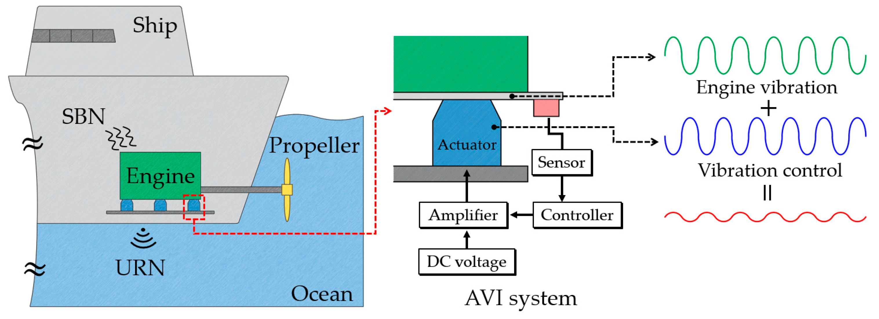
Electromagnetic actuators, meanwhile, have relatively lower precision resolution than piezoelectric actuators. However, they offer greater strength to external shocks than piezoelectric actuators. Large ships or other marine applications can undergo rapid engine acceleration or unexpected external impulse loading by shock waves to the hull of a ship. Compared to hydraulic and pneumatic actuators, electromagnetic actuators can control the high-frequency region. Therefore, considering high strength with high precision resolution and the wide frequency control region, an electromagnetic actuator is selected for an AVI system for a large ship in this work. The concept of an AVI system with an electromagnetic actuator in a large ship is illustrated in
Figure 1. The AVI system generates anti-phase counteracting dynamic forces to the engine vibration. The amplitude and frequency of external vibration detected by a real time sensor are transmitted to the controller and, based on this, the controller adjusts the frequency and current amplitude of the amplifier.
Electromagnetic actuators based on the Lorentz force can be divided into moving voice coil actuators (VCMs) [
19,
20,
21] and moving inertial mass actuators (IMAs) [
22,
23,
24]. Structurally, the IMAs and VCAs are similar in appearance, as shown in
Figure 2. However, the moving part of a VCA is the coil part, as shown in
Figure 2a. On the other hand, the coil part of the IMA as shown in
Figure 2b is fixed, and the solid core and PM are used as the moving part to generate inertial mass force. An IMA typically consists of a mass that is mechanically connected to a load and can be accelerated or decelerated to create a force. It can generate higher force compared to a VCA by using an inertial mass; an IMA is, thus, more suitable for applications that require high force.
This work mainly focuses on the electromagnetic design and analysis of an inertial mass linear actuator (IMLA) for an active vibration isolation system. First, the configuration and operation principle of the proposed IMLA are explained. Second, the generated Lorentz force of the proposed IMLA is predicted and analyzed by a simple magnetic equivalent circuit (MEC). The predicted Lorentz force is compared with the results of a finite element method (FEM). Finally, dynamic characteristics are evaluated for the eddy current damping effect in the bobbin housing, solid cores, and permanent magnet (PM). The results show that the damping effect of the bobbin is significant, which leads to a decrease in Lorentz force from the coil parts.
2. Proposed Inertial Mass Linear Actuator for Active Vibration Isolation Mount
The proposed IMLA, as shown in
Figure 3a, has a cylindrical shape with winding (coil) with the bobbin housing, an outer radial magnetized PM, and a solid core. It must be designed within a constraint volume of 90 × 90 × 110 mm
3 (
x-
y-
z axis direction as shown in
Figure 3a, respectively). The proposed IMLA is concerned with a three-axis direction active vibration isolation system that utilizes three IMLAs, which means they are used as multiple vibration isolators. Here, the bobbin housing and winding are the fixed part, whereas the PM and solid core are the moving part. When Lorentz force is generated in the winding, the reaction force is transmitted to the moving part. The moving part is combined in parallel with a circular plate spring connected with the load part.
High inductance can cause a slow time constant, which can limit the overall performance. Thus, to reduce inductance, two parallel connections to the upper and lower parts, as illustrated in
Figure 3b, are configured. Back-electromagnetic force (EMF) is induced in the winding when operating the moving part by changing the magnetic field of the PM.
Table 1 presents the required specifications for the proposed IMLA. Operation of precision control requires an operating force of at least 120 N at an operating frequency three times higher than the natural frequency
fn of the proposed IMLA. To achieve a high power per unit volume, neodymium, a PM material that has high residual flux density, was selected.
The force of the proposed IMLA is based on the Lorentz force
, which is defined as follows:
where
is the number of turns of the coil,
is the coil current,
is the coil length,
is the magnetic flux density through the coil, and
is the angle between the magnetic flux density and the current flow direction in the coil. Here, the maximum Lorentz force is generated when
or
for the same amplitudes of the other parameters in Equation (1). Because the proposed IMLA requires Z-direction force, it is structuralized as shown in
Figure 3a.
3. Lorentz Force Prediction of the Proposed IMLA by a Magnetic Equivalent Circuit with a Magnetostatic Analysis
The Lorentz force determined by Equation (1) can be quickly predicted from the magnetic flux obtained by a MEC [
24,
25,
26]. Therefore, for a magnetostatic analysis, a simple MEC analysis was conducted to elucidate the electromagnetic phenomenon and analyze the approximate Lorentz force of the proposed IMLA. For the MEC analysis, the following three assumptions are considered.
Assumption 1: The relative permeability of solid core is considered as a linear value of linear region of the solid core material.
Assumption 2: The relative permeability of the coil and bobbin housing is equal to air.
Assumption 3: The PM magnetization direction is along the X-direction.
The equivalent circuit model of the PM that can be expressed both as a flux source and as a magnetomotive force (MMF) source can be expressed as shown in
Figure 4. For the MEC in this work, an MMF source is selected. The MMF of PM
is defined as follows:
where
is the PM residual flux density,
is the vacuum permeability,
is the PM relative permeability, and
is the PM height.
The total MEC model of the proposed IMLA considering the leakage flux of the PM is illustrated in
Figure 5, where
are the reluctances of solid cores,
are the reluctances of the air gap containing the bobbing housing and winding,
are the reluctances of the PMs,
are the MMF of the PMs, and
are the MMF of the windings. The width of the coil is smaller than that of the PM, and leakage flux, which does not generate a Lorentz force because it does not cross the coil, exists at the edges of both sides of the PM. The total MEC model without PM leakage flux shows that there are five flux loops of
. Here, the practical flux that generates the Lorentz force in coils is
. However, the PM leakage flux is not usable. It is used as practical flux when the stroke is changed. This is why the width of the PM is greater than the width of the coil.
To obtain
, a mesh current analysis (loop current method) of the equivalent electric circuit is used since it is similar to the MEC. The reluctances for each section are calculated based on the shapes and are listed in
Table 2. Here,
is the absolute magnetic permeability of a material.
For the magnetostatic analysis, the maximum winding MMF when the current direction is out of the page where the moving direction is upwards is considered. The 5
5 matrix form for
based on the mesh current analysis is expressed as follows:
where
are the total reluctances related to magnetic flux for each loop, as follows:
The calculated
by inverse matrix calculation of Equation (4) are presented as follows:
Finally,
in
Figure 5 can be obtained by the given values of the following Equation (5):
It should be noted that the magnetic flux value of each side is different because the winding MMF of the upper side reduces the PM MMF of the upper side, whereas the winding MMF of the lower side is added with the lower side PM MMF when the current direction is out of the page. The calculated main parameters by Equation (6) are presented in
Table 3. Since the magnetic flux for each side is different, the Lorentz forces are also different. If the current direction is into the page, the Lorentz force of the upper side is greater than that of the lower side.
Figure 6 shows the Lorentz force with different strokes in magnetostatic FEM analysis. This analysis should be conducted because it is important to keep a constant force according to the strokes’ change. Without considering the eddy current, the Lorentz force and the inertia force of the movers are almost the same. The change in the Lorentz force and the inertial force of the movers within the change in the stroke was found to be about 5N. Flux density distribution shows that the flux density distribution of the lower solid core part is a little higher than that of the upper solid core part due to the added magnetic flux of the winding MMF and PM of the lower part.
4. Dynamic Analysis Considering Co-Simulation of the Proposed IMLA
In dynamic motion, the required load force is above 120 N at three times the operating frequency of the natural frequency of the proposed IMLA. A dynamic characteristics analysis of the proposed IMLA, which was designed by the MEC, was conducted by co-simulation with FEM model and the electric circuit, as shown in
Figure 3. The Lorentz force with the equation of linear motion is expressed as follows:
where
,
, and
are the mass, damping, and stiffness coefficient of the structure, respectively, and
,
, and
are the acceleration, velocity, and displacement, respectively. Here,
is the inertial mass force, which is equal to the load force. Therefore, the inertial force can be expressed as follows:
The Lorentz force
is generated in the coil; it is then transmitted to the moving part. However, it should be noted that the term
is generated by the eddy current effect in the PMs, solid cores, and bobbin housing, and its force can be expressed as follows [
27,
28]:
where
is the electrical conductivity of the material and
is the volume. The term
can be considered as the damping coefficient of the eddy current.
Figure 7 shows various results that are obtained according to the consideration of the eddy current loss according to the material characteristics of key components through a coupled analysis at 3
fn. Since the bobbin housing supporting the coil winding, as shown in
Figure 3, is aluminum, which has a high electrical conductivity, it is confirmed that the Lorentz force generated in the coil decreases by 23%. Applying materials with relatively low electrical conductivity can reduce the eddy current loss, thereby improving the efficiency of transmitting Lorentz forces generated from coils to inertial masses. However, an appropriate trade-off between the electrical conductivity and the strength of the material is required.
Figure 8 shows the transient dynamic analysis results of the main variables. Because current from voltage source is applied, there is an initial transient response until 60 ms.
Figure 8a shows the results of various forces, such as the Lorentz force in the coils, the inertial mass force in the PM and solid core, the load force in springs, and the transmitted force as the inertial mass force, considering the loss of eddy current of key components through a coupled analysis at 3
fn. Because the Lorentz force is the action force, the other forces are the reaction forces, and, thus, there is 180° anti-phase between the action force and the reaction forces. The load force is obtained by multiplying the generated vibration displacement by the spring coefficient, and, thus, it can be confirmed that the tendency of vibration displacement is the same. When the force transferred to the inertial mass is added to the spring force, it becomes the inertial mass force.
Figure 8b shows the results of the induced voltage and current. These show that the induced voltage and current of both coil parts are balanced waveforms according to time. The value of the peak current is 3 A, which is within the limited range of the required design.
Figure 9a presents the vibration displacement of the inertial mass (PM + solid core), which was determined to be 0.776 mm
peak-peak from the analysis. The eddy current loss of the PM and bobbin housing was determined to be 14.64 W
rms.
Figure 9b shows the inductance and the flux linkage in the upper and lower winding, which were determined to be 17.4 mH
rms and 0.288 Wb
rms, respectively.
Figure 10a shows a comparison of the inertial and damping forces according to the eddy current loss of the material used when the current peak is 3A. In general, eddy current loss occurs when magnetic flux passes through a material with a high electrical conductivity. The Lorentz force generated by the coil reduces the force transmitted to the inertial mass because of the eddy current loss of the bobbin housing (aluminum) supporting the coil. The reduced force transmitted to the inertial mass is the damping force and is evaluated to have a peak of about 47 N.
Figure 10b presents a comparison of the flux linkage of a half coil according to the eddy current loss of the material used when the current peak is 3A. The material (aluminum) of the bobbin housing that supports the coil causes an eddy current, which prevents the magnetic flux from passing through the coil. Therefore, it is shown that the flux linkage is reduced.
All constraints must be satisfied in this work. It was confirmed that the constraints of the phase difference between the force and the current, the phase difference from the magnitude to the operating force at 3
fn, the frequency operating range, the linearity of the force, the dynamic range, and the harmonic distortion were all satisfied. In
Section 3, a difference in force between the upper and lower coils is presented in
Table 3. However, there is no an unbalance effect for each coil’s induced voltage, current, and flux linkage when operating the proposed IMLA in dynamic operation, as shown in
Figure 8b and
Figure 9b.
Figure 11 shows the flux line, Lorentz force on edge of the bobbin housings and coils, flux density vector, and flux density distribution at the proposed IMLA model at 3
fn. Leakage flux lines, as shown in
Figure 11a, are investigated. When the inertial mass part is moved, leakage flux is utilized as linkage flux through the coils, which generate upper and lower direction Lorentz forces.
Improving thrust force is possible not only from an optimization standpoint but also from material selection.
Figure 12 shows the B–H nonlinear curve according to the three materials (S20C, S45C, and SPCC) of carbon steel. In the linear region of the B–H nonlinear curve, when a material with a high permeability is effective and a material has a high saturation magnetic flux density, the thrust force of the linear actuator applied with S20C material is improved by more than 10%.
Figure 13 shows a comparison of various forces and vibration displacement according to the solid core material of the proposed IMLA model at 3
fn. The thrust force performance of the S20C material was improved by more than 10% compared to the S45C material, as shown in
Figure 13a. It has been confirmed that S20C and SPCC materials have almost the same performance. When a high thrust is required within such a limited volume, it is necessary to select and apply a solid core material with a high permeability and saturation magnetic flux density. As forces increase, the vibration displacement also increases, as shown in
Figure 13b.


