Article

Design and Analysis of a Novel Actuator with a Double-Roller Gear Drive

1
School of Mechanical and Electrical Engineering, Soochow University, Suzhou 215137, China
2
School of Rail Transportation, Soochow University, Suzhou 215137, China
*
Authors to whom correspondence should be addressed.
Actuators 2023, 12(7), 292; https://doi.org/10.3390/act12070292
Submission received: 29 May 2023 / Revised: 7 July 2023 / Accepted: 13 July 2023 / Published: 18 July 2023

Abstract

:
In recent years, with the development of robot transmission technology, the market demand for high-performance actuators, which can be applied to lower limb exoskeleton assist robots, is increasing. These robots help achieve human–robot interaction through rigid and flexible coupling, and they can ensure the flexibility of the elderly or patients in daily walking and rehabilitation training. A novel actuator with a double-roller gear drive structure is proposed with high bearing capability and high transmission efficiency due to multi-tooth rolling contact with small tooth difference such that friction is greatly reduced in the transmission process compared to what occurs in involute planetary transmission. The bearing capacity of the tooth surface was analyzed by using the loaded contact analysis method. Finally, a prototype was manufactured with the 3D printer, and the maximum output torque of the developed actuator was tested with an experimental setup. The results show that this novel actuator, with its double-roller gear drive, has huge potential for use in the hip joint of an exoskeleton robot.

1. Introduction

Robots play a significant role in human life, enhancing productivity and efficiency, and improving the quality of life. They assist us in various tasks and industries including manufacturing, healthcare, agriculture, and even personal assistance. One particular type of robot, the exoskeleton robot, has a profound impact on human life. Exoskeleton robots, also known as wearable robots, are designed to enhance the physical capabilities of humans. An exoskeleton robot consists of a wearable framework and actuators that provide support and augment the user’s strength and endurance. The actuators in exoskeleton robots are crucial components that enable motion and force transmission, and they must meet specific requirements for exoskeleton robots including reliability, durability, and power efficiency. They should be capable of providing precise and controlled motion to assist and enhance a user’s movements. Moreover, they need to be lightweight and ergonomic to ensure user comfort and avoid excessive fatigue during prolonged use. Orion [1] et al. developed an auxiliary hand exoskeleton that has good flexibility because of using silicone resin, which can reduce impact and improve dimensional accuracy. The Research Institute of the University of Pisa in Italy designed a full-body exoskeleton robot system (Body Extender), which drove a robot to walk through impedance control. There are a total of six force sensors in this robot. The laboratory at the University of California, has proposed an exoskeleton (BLEEX) [2,3] that can withstand body weight and external loads and includes hydraulic actuators, 30 sensors, and a drive power supply. Onen [4] et al. developed a wearable exoskeleton robot (WSE) driven by a DC servo motor that uses electric actuators to provide power because of its compact and lightweight design requirements. The mechanism, drive, and power transmission of most upper-limb exoskeleton robots are classified, compared, and summarized [5]. Electric actuators, which utilize electrical energy to generate motion, offer precise control and high torque and are suitable for applications requiring fine movements and accuracy. The hydraulic actuator, which [6] has a large output torque and power density, has a certain flexibility, meeting the demand for explosive torque during the startup of an exoskeleton robot for the lower limbs. However, controlling the gait to fit the natural posture is challenging because of the large inertia and obvious hysteresis effect. The power of the actuator can be dominated by external retroaction. When the series elastic actuator (SEA) measures the elastomer to regulate the drift, a strain instrument is applied to the lower-limb exoskeleton robot actuator to record force and torque [7].
Gear transmission systems play crucial roles in robot actuators by enabling power transmission and motion transmission and providing positioning and precision control. The effective design and optimization of gear transmission systems are essential for optimizing the performance and functionality of robots. To avoid motor power transfer loss, the actuation system must have a high torque efficiency and mechanical bandwidth for high torque transmission. Additionally, when an exoskeleton robot is used for human walking, it should reduce the human burden as much as possible, and so, a light and compact drive system is designed to meet the requirements. However, low control capacity and rest friction are still not resolved [8]. The cycloid reducer reduces speed by utilizing the tooth difference. Compared with the harmonic drive, with an identical speed-reducing ratio, the cycloid reducer, with a high reducing ratio, has better carrying capacity [9]. The cycloid reducer can achieve a low speed-reducing ratio and high reducing ratio because the cycloid reducer has a wider speed-reducing ratio range. The cycloid reducer has become the widely applied type of reducer for industrial robots. However, it is difficult to directly apply traditional ready-made cycloid reducers to exoskeleton robots because of their large sizes and high weights [10]. The design of a portable cycloid reducer, which can be effectively applied to exoskeleton robots, is put forward. Li et al. introduced unloaded tooth contact analysis to determine instantaneous meshing information. Combining the Boussinesq force–displacement relationship in elastic half space with the influence coefficient method, a tooth flexibility model considering tooth contact deformation was established. Then, the loads, contact patterns, and loaded transmission error were calculated by enforcing the compatibility and equilibrium conditions [11,12,13]. Sensinger [14] put forward the idea of a cycloid reducer that uses roller bearing with modest attrition factors to take the place of a free roller. In order to devise an efficient cycloid reducer, a compact needle bearing was used instead of a ball bearing [15,16]. The type of contact between a cycloid and pinion is point contact, rather than theoretical line contact, which greatly improves mechanical efficiency [17]. High energy efficiency at a low speed-reducing ratio is a cycloid reducer’s main advantage; then, an actuator model was set up by assembling an electrical motor with high torque density. There is an increasing demand for high-performance gear drives, and these can achieve larger reduction ratios. In contrast, the reduction ratios provided by mainstream harmonic drives in the market cannot meet the demand of the market. Therefore, planetary, wolfrom, cycloidal, and various other types of transmission structures have been promoted [18,19,20]. Cycloidal reducers [21] allow robots to exhibit excellent performance (i.e., high robustness, torsional stiffness, mechanical efficiency). The main reason for their generating these performances is their large stress area and rolling contact [22]. Many researchers have analyzed various parameters of cycloidal gears [23,24]. In order to further optimize the design, researchers have considered tooth profile modification to reduce machining errors. The use of needle roller bearings instead of free rollers greatly improves mechanical efficiency and reduces friction losses [25]. A compact low deceleration cycloidal transmission has been developed that is low-cost, capable of 3D printing, and uses ready-made bearings and steel structures [26]. Jea-Luc set up a theoretical approach for estimating cycloidal gear reducers’ effectivenesses; after experimental verification, the error was relatively small compared to the actual situation [27]. Pablo López García et al. proposed an evaluation criterion strongly constrained by HRI applications and used it to evaluate the performance of traditional and emerging robot transmission technologies, particularly in terms of weight and efficiency [28]. The cycloidal reducers proposed above can also be connected to an electric motor that can be applied to an exoskeleton robot.
The rest of this paper is set as follows: The Section 2 provides a brief explanation of the fundamental geometric design and operating mechanism of a novel actuator with a double-roller gear drive. The Section 3 addresses a semi-analytical load distribution model based on an investigation of tooth contact under loaded and unloaded conditions. A gear tooth flexibility model is created by integrating the Boussinesq force–displacement relationship in elastic half space with the effect coefficient approach. The impacts of various torque sizes on contact stress, load transmission error, and transmission ratio are studied by using the suggested model in the Section 4, which also presents an experimental verification. The entire text is distilled in the Section 5.

2. Mechanical Structure and Gear Geometry Design

2.1. Explosion Diagram and Working Principle

Figure 1 shows the three-dimensional model and physical prototype of the novel actuator. Its diameter is 80 mm and its height is 78.5 mm. It mainly consists of a hexagon socket cylindrical bolt (1), drive housing (2), retaining ring (3), cross roller bearing (4), output end (5), inner needle (6), sleeve (7), outer needle roller (8), retaining ring (9), solid needle roller bearing (10), retainer (11), eccentric sleeve (12), right side of holder (13), motor front end cap (14), C-type flat key (15), motor shaft (16), rotor (17), deep groove ball bearing (18), determinant (19), magnetic encoder (20), and motor housing (21). Unlike common involute gear drives, it is a complex eccentric rotating planetary transmission structure.
The input shaft drives the platform’s rolling and the eccentric sleeve maintains the disc’s touching with the rollers. The disc’s rotational movement is sent to the output axis through output spaces situated on the retainer and the needles surrounding the output disc. The advantage of this mechanism is that the meshing pair possesses the characteristic of rolling contact to reduce the loss of meshing power, improve traditional efficiency, and simultaneously have the characteristics of multiple-tooth contact of planetary transmission with small tooth difference. Compared with involute planetary transmission, the double-roller structure has the benefits of compact size, low weight, high transmission ratio, high positioning accuracy, and better bearing capacity due to the small difference in the number of teeth and multi-tooth contact features [29].

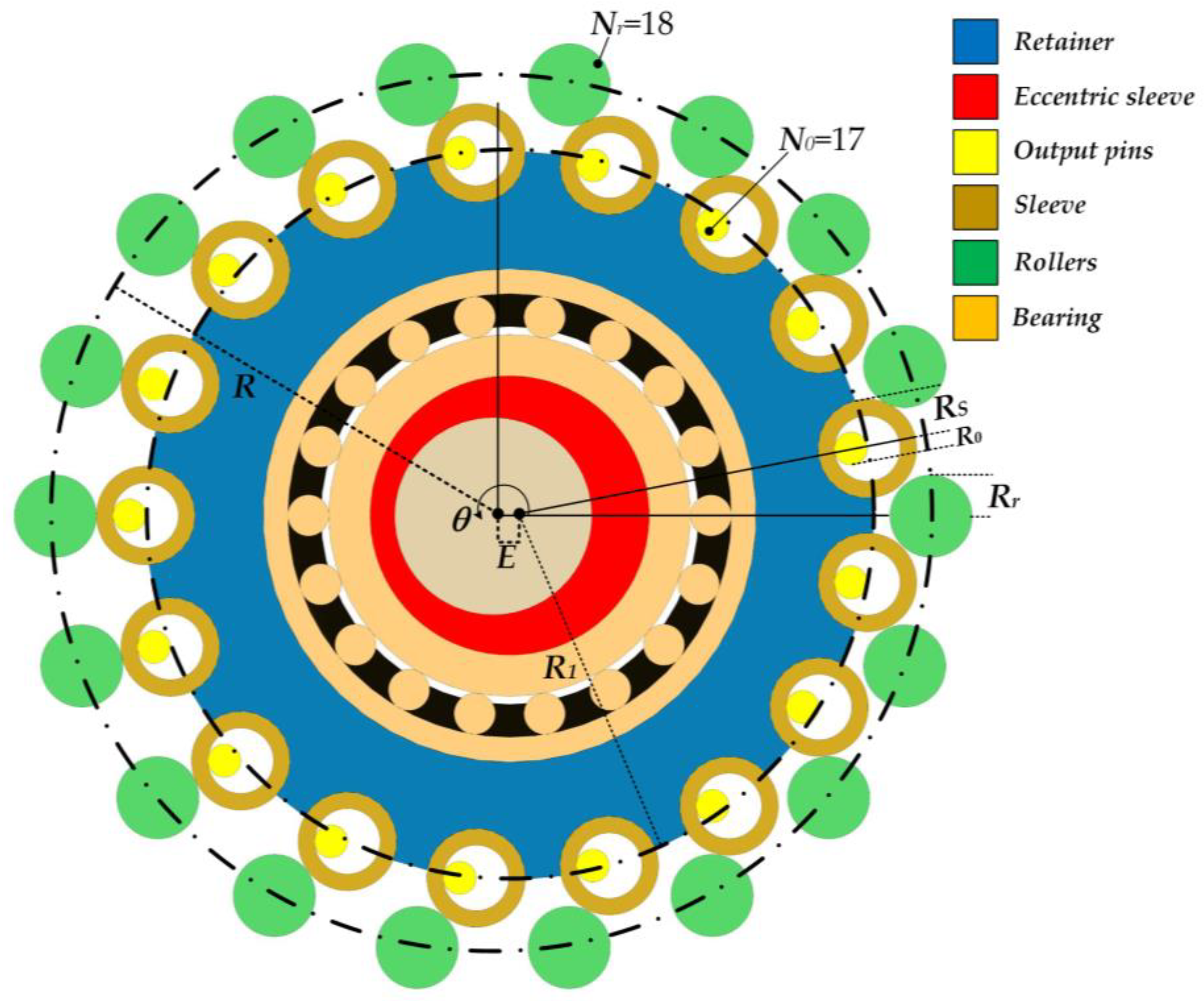
2.2. Geometric Parameters of the Double-Roller Gear Pair

The basic geometric shape is expressed in Figure 2. The 17 sleeves (expressed in beige) roll over the rollers (here 18, displayed in green) on the outer circumference with a radius of R, with each roller having a radius of Rr. The sleeve (beige) and retainer (blue) come into contact with the eccentric sleeve (red) through the bearing (gold). Then, they are driven by an eccentric sleeve on the input axis (brown) that rotates around the input shaft with an eccentricity of E related to the rotation shaft. Finally, the required moment is transmitted to the output axis through the output pins (yellow).
The ordinary representation for the ratio of transmission (N) of the double needle roller structure with N s sleeves and N r rollers is as follows:
N = N S N r N S
where the contrast N r N S = 1 guarantees the maximum meeting region for power transmission. Therefore, substituting N S = N r 1 , the above expression can be simplified thus:
N = N r 1 .
The sleeve motion profile can be ingeniously represented thus:
s x ( θ ) = R cos ( θ ) R r cos ( θ + α ) E cos ( N r θ ) s y ( θ ) = R sin ( θ ) + R r sin ( θ + α ) + E sin ( N r θ )
where α denotes the inclination of the sleeve in relation to the roller:
α = tan 1 [ sin ( ( N r 1 ) θ ) cos ( ( N r 1 ) θ ) R E N r ]
and θ [ 0 , 2 π ] represents the angle around the input axis.

3. Model for the Load Distribution

In this part, a load distribution model of a double-roller gear drive is developed, and this is seen as a three-dimensional resilient contact question to exactly describe the influence of flank profile and lengthways modification. The semi-analytic model is proposed and assayed under the ensuing assumptions:
  • The force spread on a pair of teeth does not influence stretch variations on nearby tooth couples.
  • In a quasi-static process, the rotating speed and inertia forces of the locomotor components are ignored.
  • It is assumed that the curved shape of gear tooth exteriors in the meeting area remains invariable.
  • The friction that exists between contact tooth couples is ignored.
Figure 3 depicts the general layout of the mentioned semi-analytic model based on the aforementioned assumptions. The design size, modification, material attributes, and inflicted force are the initial arguments for the model previously mentioned. The tooth profile and roller profile expressed by the foregoing arguments are converted into an overall coordinate frame to execute unloaded tooth contact analysis for obtaining the meshing information. Then, the Boussinesq force–displacement relationship in the elastic half-space is expressed by using the influence coefficient method, and a tooth compliant model that takes into account tooth contact deformity is set up. The final step is to offer a series of balancing and coordination criteria, which are utilized to estimate the loads, load transmission error (LTE), contact relationship, contact pressure, and transmission ratio during the transmission process.

3.1. Analysis of the Unloaded Tooth Contact

Unloaded tooth contact analysis is carried out in both dimensions to precisely establish the immediate center point for possible meshing areas. The ordinate frames for unloaded TCA (Tooth Contact Analysis) are displayed in Figure 4. S 1 ( x 1 , y 1 ) and S 2 ( x 2 , y 2 ) are fixedly attached to the needle roller and cycloidal gear, respectively, and the fixed axis system S f ( x f , y f ) that coincides with S 1 is fastened on the rack in an exact manner. The location vector r f ( 1 ) ( θ r ) and its unit normal vector n f ( 1 ) ( θ r ) are expressed in S f thus:
r f ( 1 ) ( θ r ) = [ R cos ( n σ r ) + R r cos ( θ r ) R sin ( n σ r ) R r sin ( θ r ) 0 1 ] ,
n f ( 1 ) ( θ r ) = r f ( 1 ) ( θ r ) θ r × k | r f ( 1 ) ( θ r ) θ r × k | ,
where n is the total number of rollers, σ r is an indexing angle of the needles and its value is σ r = 2 π N r , k = [0, 0, 1] is an unit normal vector, and θ r is the angle argument of the roller profile.
The position vector r f ( 2 ) ( θ g a , ϕ p i , ϕ i t , θ c ) and its unit normal vector n f ( 2 ) ( θ g a , ϕ p i ) are expressed in S f in an equal manner:
r f ( 2 ) ( θ g a , ϕ p i , ϕ i t , θ c ) = [ [ R 1 cos ( n θ g a θ g a / 2 ) + R s cos θ c ] cos ( ϕ p i ) + [ R 1 sin ( n θ g a θ g a / 2 ) + R s sin θ c ] sin ( ϕ p i ) + E cos ( ϕ i t ) [ R 1 sin ( n θ g a θ g a / 2 ) + R s sin θ c ] cos ( ϕ p i ) [ R 1 cos ( n θ g a θ g a / 2 ) + R s cos θ c ] sin ( ϕ p i ) + E sin ( ϕ i t ) 0 1 ]
n f ( 2 ) ( θ g a ) = r f ( 2 ) ( θ g a ) θ g a × k | r f ( 2 ) ( θ g a ) θ g a × k | ,
where ϕ p i is the rotation angle, ϕ i t is the crank axle’s input angle, θ c is an included angle between the articulated line from the sleeve center to engagement point M and the horizontal line, and θ g a is an angle argument.
Two requirements must be met for it to be possible to perform the unloaded TCA: the radius vectors must be coincident and the convergence of the normal vectors of the gear and roller contours must occur at the same meeting locations [15,30]. Hence,
n f ( 1 ) ( θ r ) = n f ( 2 ) ( θ g a , ϕ p i ) r f ( 1 ) ( θ r ) = r f ( 2 ) ( θ g a , ϕ p i , ϕ i t )
To calculate the unit normal vectors, | n f ( 1 ) | = | n f ( 2 ) | = 1 , three formulas that are not linear with a few unknowns ( θ r , θ g a , ϕ p i and ϕ i t ) can be set up. The input crank axle angle ϕ i t is given, and the other three unknown arguments can be computed.
Then, the backlash ϕ a l i and the angle of rotation ϕ d are expressed as below [15,31]:
ϕ a l i = ϕ d ϕ p i ϕ d = max ( ϕ p i )
where the backlash ϕ a l i is the maximum revolve angle for all possible melding gear transmission pairs and the revolve angle ϕ d is the peak value in the rotation angles.

3.2. Tooth Compliance Model

After defining the source sites of the probable meeting area in the no-load TCA, the subsequent phase is to ascertain the tooth adaptability of the contact components. The tooth depth is shorter because the tooth thickness of the dedendum is larger, and the contribution of contact deformation to tooth deformation is much greater than that of bending deformation and shear deformation. Therefore, only considering contact deformation is enough for applications in engineering [32]. This paper introduces the Boussinesq solution to tooth contact deformation in the elastic half space [33,34].
Figure 5 reveals the meeting situation of the double needle structure. From the lateral view, the two coordinate frames are defined at the same base point at the beginning meeting point (area) as expressed in Figure 5a. In Figure 5b, the actual contact pattern and contact line between the roller pin and sleeve are depicted. As illustrated in Figure 5c, the tooth flank is illustrated in the coordinate frame, where x and y stand for the gear outline and width directions, respectively. The possible meeting region is split into an interface lattice, and each grid element is represented by a single meeting point. The meeting area of each gear pair is split into b mesh elements with the same diameter in the outline orientation. In the width direction, the same possible meeting area is segmented into c mesh elements. Every meeting mesh element’s region is Ω = 2 ξ × 2 η . The meeting deformation δ c at a point ( x i , y i ) can be expressed as follows:
δ c = ( 1 μ 1 2 π E 1 + 1 μ 2 2 π E 2 ) Ω b ( x , y ) [ ( x x ) 2 + ( y y ) 2 ] 1 / 2 d x d y ,
where μ and E stand for the Poisson’s ratio and Young’s modulus, respectively, and indexes 1 and 2 indicate roller pin and sleeve, respectively. b ( x , y ) is the dispersed stress in the meeting region Ω .
The preliminary spacings between both sides are set as ω 1 i j and ω 2 i j , and they are able to be expressed thus:
ω 1 i j = { ρ 1 2 [ 2 ξ i 2 ξ ( b / 2 + 1 ) ] 2 } 1 / 2 | ρ 1 | , i = 1 , 2 , , b ; j = 1 , 2 , , c ,
ω 2 i j = { ρ 2 2 [ 2 ξ i 2 ξ ( b / 2 + 1 ) ] 2 } 1 / 2 | ρ 2 | , i = 1 , 2 , , b ; j = 1 , 2 , , c ,
where ρ 1 is the curvature semidiameter of the roller and ρ 2 is the curvature semidiameter of the sleeve at the location of contact.
In the case of PCM (Partially Crowned Modification),
Δ p ( d ) = { R p R p 2 ( | d | L 1 / 2 ) 2 , L / 2 d < L 1 , L 1 / 2 d L / 2 0 , L 1 / 2 d L 1 / 2 .
On the basis of Equation (14), the initial spacing of the sleeve surface can be redrafted thus:
ω 2 i j P C M = ω 2 i j + { { R P 2 [ 2 η j 2 η ( c / 2 + 1 ) ] 2 } 1 / 2 R p } G ( x ) , i = 1 , 2 , , b ; j = 1 , 2 , , c ,
where G ( x ) = { 1 , x > 0 0 , x 0 and x = ( 2 j 1 ) / ( c + 1 ) 1 L 1 / L .
In such a case, the improved portability approach’s total formula for the multidimensional flexible contact may be represented as follows:
k = 1 n P k f i j = δ t ω 1 i j ω 2 i j , k = 1 , 2 , , n ; i = 1 , 2 , , b ; j = 1 , 2 , , c ,
where f i j is the effect factor that is able to be expressed as follows:
f i j = ( 1 μ 1 2 π E 1 + 1 μ 2 2 π E 2 ) { ( x ¯ + ξ ) ln [ ( y ¯ + η ) + ( y ¯ + η ) 2 + ( x ¯ + ξ ) 2 ( y ¯ η ) + ( y ¯ η ) 2 + ( x ¯ + ξ ) 2 ] + ( y ¯ + η ) ln [ ( x ¯ + ξ ) + ( y ¯ + η ) 2 + ( x ¯ + ξ ) 2 ( x ¯ ξ ) + ( y ¯ + η ) 2 + ( x ¯ ξ ) 2 ]   ,   i = 1 , 2 , , b ; j = 1 , 2 , , c . + ( x ¯ ξ ) ln [ ( y ¯ η ) + ( y ¯ η ) 2 + ( x ¯ ξ ) 2 ( y ¯ + η ) + ( y ¯ + η ) 2 + ( x ¯ ξ ) 2 ] + ( y ¯ η ) ln [ ( x ¯ ξ ) + ( y ¯ η ) 2 + ( x ¯ ξ ) 2 ( x ¯ + ξ ) + ( y ¯ η ) 2 + ( x ¯ + ξ ) 2 ] }
In addition to displacement requests, two limitations on force are also exerted. The normal force f is computed by using the following formula:
k = 1 n P k = f 4 ξ η   ,   P k 0   , k = 1 , 2 , , n ,
where the stress dispersion in the meeting area ought to be nonnegative.
The preceding linear formulas [27,34] with fringe conditions are able to be computed to derive the meeting area, meeting pressure, and meeting deformation. Therefore, the tooth flexibility is expressed as follows:
C c = δ c f .
Gear tooth flexibility is a nonlinear formula involving the geometries, powers, and material characters of gear teeth. The numerical values of tooth flexibility and normal force are able to be computed by using a process of iteration, which will be outlined in the next section.

3.3. Loaded Tooth Contact Analysis

As expressed in Figure 6, the suitability requirements must be met to compute the number of contact tooth pairs that is able to be expressed, as shown below [35]:
c o n t a c t : Δ ϕ d > ϕ a l i ,   α i = Δ ϕ d ϕ a l i n o   c o n t a c t : Δ ϕ d < ϕ a l i ,   α i = 0
where Δ ϕ d is the augmenter of the revolve angle and α i is the small angular displacement of the gear tooth.
The force–torque stable balance formula is able to be shown thus:
T = i = 1 n 1 α i l i 2 / C n i ,
where the lever arm l i is able to be exactly expressed as follows:
l i = E tan θ r cos ϕ i t E sin ϕ i t + R sin n σ r + R tan θ r cos n σ r tan 2 θ r + 1 .
The iterative computation is duplicated to get a solution, as expressed in Figure 3. First of all, two initializations of load and angular displacement can be selected to seek the solution of the connectivity and balance formulas, on the basis of using Equations (12)–(19) simultaneously, and then, the backlash is computed through unloaded TCA. Once the force and angular rotation enter the formula systems, all values are renewed. When the changes in force and angular rotation astriction fall within 2%, the iterative program must be stopped to generate the forces, meeting pressure, meeting model, transmission ratio, and load transmission error (LTE).

4. Theoretical and Experimental Results

The contact stress distribution, load-bearing capacity, and transmission error of the double-roller gear pair of the actuator are simulated by the above calculation model. Assuming that the material properties of the gear pair are the same, Poisson’s ratio is 0.3, and Young’s modulus is 206 GPa, the basic design parameters are shown in Table 1.
The-load bearing capacity and transmission error are theoretically analyzed by the proposed model. Figure 7 expresses the stress distribution of the gear pairs under different crankshaft angles and torques for the FCM (Fully Crowned Modification) type, illustrated in 3D plots. As expressed in Figure 7a, when it comes to FCM, at a crankshaft angle of 0 degrees, the contact stress in the middle part of a single tooth is relatively small and the stress concentrating on both sides can reach a maximum of 532 MPa. As different teeth mesh, the maximum stresses of different teeth continue to decrease. From the figure, it can be seen that Tooth No. 3 does not mesh due to the systematic errors.
Similarly, as shown in Figure 7b, at a crankshaft angle of 150 degrees, there is also a situation of stress concentration and maximum stress reduction. The maximum stress can reach 510 MPa. Compared to the previous situation with a crank angle of 0 degrees, the maximum stress has decreased. The difference is the meshing gear number starts with Gear No. 8 and ends with Gear No. 16 at 150 degrees. It is obvious that as the angle increases, the first meshing teeth change regularly.
When the applied torque increases, the maximum stress also increases, as expected. In Figure 7c, at an input torque of 10 Nm with a crankshaft angle of 0 degrees, compared to Figure 7a, the maximum stress can reach 763 MPa with a slight increase. Similarly, at a crankshaft angle of 150 degrees, the maximum stress can reach 724 MPa. As expressed in Figure 7e, if the applied torque is 20 Nm with a crankshaft angle of 0 degrees, the maximum stress reaches 1077 MPa. As expressed in Figure 7f, if the applied torque is 20 Nm with a crank angle of 150 degrees, the maximum stress reaches 1045 MPa. As shown in Figure 7g, if the applied torque is 40 Nm with a crank angle of 0 degrees, the maximum stress reaches 1579 MPa. As expressed in Figure 7h, if the applied torque is 40 Nm with a crank angle of 150 degrees, the maximum stress reaches 1498 MPa. The stress distribution shown in the above figures is basically in line with the actual applied torques.
Figure 8 shows the situation of the crankshaft angle and load transmission error under four different torques. From the figure, it can be seen that as the crankshaft angle increases step by step, the load transmission error presents a periodic change similar to a sine wave. Among the load transmission error values, the maximum absolute value of the load transmission error can reach 81 arcsec, and the minimum values is only 6 arcsec. As the applied torque increases, the absolute value increases gradually. When the torque is 40 Nm, the transmission error is the largest. When the applied torque is 5 Nm, the transmission error is the smallest. The image representation still conforms to the real-life situation.
Figure 9 shows the situation of the crank angle ϕ in and gear ratio under four different torques. From the figure, it can be seen that as the crank angle increases step by step, the gear ratio presents periodic changes. The crank angle ranges from 0 to 180 degrees, and the maximum gear ratio can reach 18.1, while the minimum transmission ratio is only 16.5. As the input torque increases, the gear ratio gradually increases. When the output torque is 5 Nm, the fluctuation of the gear ratio is the smallest. When the output torque is 40 Nm, the fluctuation is the maximum, as expected.
Figure 10 shows the situation of the crank angle ϕ in and number of teeth in contact under four different torques. The figure demonstrates that as the crankshaft angle is steady augmented, the number of touching teeth presents a periodic change similar to a square wave. When the crank angle changes from 0 to 180 degrees, the numbers of contact teeth, mainly, are 7 and 8. Take one cycle as an example: when the crank angle is 0 degrees, the number of touching teeth is 7, and when the crankshaft angle changes from 2 to 18 degrees, the number of touching teeth is 8. Under the performance of four different torques, the four curves basically coincide.
Taken from an experimental test, the assembled prototype is expressed in the following Figure 11. Figure 11 depicts the structure of the external retaining ring, a physical image of the structure of the double-roller gear drive, the overall appearance of the prototype, and the internal components inside the prototype.
The prototype was confirmed through various kinds of tests, and we proved the function of the transmission device and the whole actuator. An experimental device was built as expressed in Figure 12. The entire experimental setup included a workbench bracket, the novel actuator, a supporting rod, a driver power supply, and a heavy lifting hammer. As represented in Figure 12, the novel actuator was driven by a 36 V power supply and the output end was fixed to the rod through two bolts. The right end of the rod was connected to two 2 kg weight hanging hammers through a steel wire, and the output line was connected to an upper computer through a CAN interface. The output torque of the actuator could be verified by controlling the software speed and current of the upper computer to drive the reducer to rotate. The maximum output torque of the actuator could reach about 20 Nm. All experiments were conducted on a 36 V electric source, and the driver joint was connected to the upper computer through a serial interface to detect and record position, speed, and current data.

5. Conclusions

A novel actuator with a double-roller gear drive, which can be applied in exoskeleton robots, was proposed in this paper. The theoretical meshing verification of the gear pair was performed by using the loaded tooth contact analysis model. The three-dimensional model of the gear box was built and its prototype was assembled with components printed by a 3D printer. The experimental test results show a good performance on bearing capacity.
In the process of structure designing, the needle roller bearing was used; this greatly reduces the generation of friction during power transmission, and it can be applied to compact reducers with high mechanical efficiency requirements. In addition, a sleeve was also used as the contact structure of the external needle roller; this greatly reduces energy loss and friction during movement, and greatly improved the mechanical efficiency of the entire actuator. Therefore, it can meet the power requirements of exoskeleton robots.
The internal stiffness and load transmission error have been studied and validated by an experimental test. In the future, in-depth research can be conducted to optimize the various performance indicators of the reducer such as by reducing transmission errors. Therefore, the aforementioned novel actuator has huge potential for use in exoskeleton robots.

Author Contributions

Conceptualization, X.L. and Y.L.; Methodology, X.L.; Validation, X.L. and Y.L.; Analysis, X.L. and W.N.; Writing—Original Draft Preparation X.L. and R.G.; Writing—Review and Editing, X.L. and R.G.; Supervision, X.L. and R.G. All authors have read and agreed to the published version of the manuscript.

Funding

This work was supported by the National Natural Science Foundation of China (Grant No. 52005354) and the Natural Science Foundation of Jiangsu Province (Grant No. BK20220497).

Data Availability Statement

Not applicable.

Conflicts of Interest

The authors declare no conflict of interest.

References

  1. Ramos, O.; Munera, M.; Moazen, M.; Wurdemann, H.; Cifuentes, C.A. Assessment of Soft Actuators for Hand Exoskeletons: Pleated Textile Actuators and Fiber-Reinforced Silicone Actuators. Front. Bioeng. Biotechnol. 2022, 10, 924888. [Google Scholar] [CrossRef]
  2. Ghan, J.; Steger, R.; Kazerooni, H. Control and system identification for the Berkeley lower extremity exoskeleton (BLEEX). Adv. Robot. 2006, 20, 989–1014. [Google Scholar] [CrossRef]
  3. Kazerooni, H.; Steger, R.; Huang, L.H. Hybrid control of the Berkeley Lower Extremity Exoskeleton (BLEEX). Int. J. Robot. Res. 2006, 25, 561–573. [Google Scholar] [CrossRef]
  4. Onen, U.; Botsali, F.M.; Kalyoncu, M.; Tinkir, M.; Yilmaz, N.; Sahin, Y. Design and Actuator Selection of a Lower Extremity Exoskeleton. IEEE/ASME Trans. Mechatron. 2014, 19, 623–632. [Google Scholar] [CrossRef]
  5. Gopura, R.; Bandara, D.S.V.; Kiguchi, K.; Mann, G.K.I. Developments in hardware systems of active upper-limb exoskeleton robots: A review. Robot. Auton. Syst. 2016, 75, 203–220. [Google Scholar] [CrossRef]
  6. Zoss, A.B.; Kazerooni, H.; Chu, A. Biomechanical design of the Berkeley lower extremity exoskeleton (BLEEX). IEEE-ASME Trans. Mechatron. 2006, 11, 128–138. [Google Scholar] [CrossRef]
  7. Radford, N.A.; Strawser, P.; Hambuchen, K.; Mehling, J.S.; Verdeyen, W.K.; Donnan, A.S.; Holley, J.; Sanchez, J.; Nguyen, V.; Bridgwater, L.; et al. Valkyrie: NASA’s First Bipedal Humanoid Robot. J. Field Robot. 2015, 32, 397–419. [Google Scholar] [CrossRef]
  8. Del Prete, A.; Mansard, N.; Ramos, O.E.; Stasse, O.; Nori, F. Implementing Torque Control with High-Ratio Gear Boxes and Without Joint-Torque Sensors. Int. J. Humanoid Robot. 2016, 13, 29. [Google Scholar] [CrossRef]
  9. Li, T.X.; An, X.T.; Deng, X.Z.; Li, J.F.; Li, Y.L. A New Tooth Profile Modification Method of Cycloidal Gears in Precision Reducers for Robots. Appl. Sci. 2020, 10, 1266. [Google Scholar] [CrossRef] [Green Version]
  10. Lee, K.; Hong, S.; Oh, J.-H. Development of a Lightweight and High-efficiency Compact Cycloidal Reducer for Legged Robots. Int. J. Precis. Eng. Manuf. 2019, 21, 415–425. [Google Scholar] [CrossRef]
  11. Li, X.; Huang, J.; Ding, C.; Guo, R.; Niu, W. Dynamic Modeling and Analysis of an RV Reducer Considering Tooth Profile Modifications and Errors. Machines 2023, 11, 626. [Google Scholar] [CrossRef]
  12. Li, X.; Tang, L.; He, H.; Sun, L. Design and Load Distribution Analysis of the Mismatched Cycloid-Pin Gear Pair in RV Speed Reducers. Machines 2022, 10, 672. [Google Scholar] [CrossRef]
  13. Zhang, T.; Li, X.; Wang, Y.W.; Sun, L.N. A Semi-Analytical Load Distribution Model for Cycloid Drives with Tooth Profile and Longitudinal Modifications. Appl. Sci. 2020, 10, 4859. [Google Scholar] [CrossRef]
  14. Sensinger, J.W. Efficiency of High-Sensitivity Gear Trains, Such as Cycloid Drives. J. Mech. Des. 2013, 135, 9. [Google Scholar] [CrossRef]
  15. Li, X.; Li, C.Y.; Wang, Y.W.; Chen, B.K.; Lim, T.C. Analysis of a Cycloid Speed Reducer Considering Tooth Profile Modification and Clearance-Fit Output Mechanism. J. Mech. Des. 2017, 139, 12. [Google Scholar] [CrossRef]
  16. Xu, L.X.; Chen, B.K.; Li, C.Y. Dynamic modelling and contact analysis of bearing-cycloid-pinwheel transmission mechanisms used in joint rotate vector reducers. Mech. Mach. Theory 2019, 137, 432–458. [Google Scholar] [CrossRef]
  17. Jiang, N.; Wang, S.; Yang, A.; Zhou, W.; Zhang, J. Transmission Efficiency of Cycloid–Pinion System Considering the Assembly Dimensional Chain. Appl. Sci. 2022, 12, 11917. [Google Scholar] [CrossRef]
  18. Chen, Q.; Wang, A.Y.; Li, T.T.; Li, C.F.; Jiao, Q.C. Sulfation of pachyman with chlorosulfonic acid using the improved Wolfrom method. Chin. J. Polym. Sci. 2006, 24, 637–646. [Google Scholar] [CrossRef]
  19. Hsieh, C.-F.; Fuentes-Aznar, A. Performance prediction method of cycloidal speed reducers. J. Braz. Soc. Mech. Sci. Eng. 2019, 41, 186. [Google Scholar] [CrossRef]
  20. Wang, Y.; Qian, Q.; Chen, G.; Jin, S.; Chen, Y. Multi-objective optimization design of cycloid pin gear planetary reducer. Adv. Mech. Eng. 2017, 9, 1687814017720053. [Google Scholar] [CrossRef]
  21. Slapak, V.; Ivan, J.; Kyslan, K.; Hric, M.; Durovsky, F.; Paulisin, D.; Kocisko, M. Measurement and Modelling of a Cycloidal Gearbox in Actuator with Permanent Magnet Synchronous Machine. Machines 2022, 10, 344. [Google Scholar] [CrossRef]
  22. Droukas, L.; Doulgeri, Z. Rolling Contact Motion Generation and Control of Robotic Fingers. J. Intell. Robot. Syst. 2016, 82, 21–38. [Google Scholar] [CrossRef]
  23. Ren, Z.Y.; Mao, S.M.; Guo, W.C.; Guo, Z. Tooth modification and dynamic performance of the cycloidal drive. Mech. Syst. Signal Proc. 2017, 85, 857–866. [Google Scholar] [CrossRef]
  24. Shin, J.H.; Kwon, S.M. On the lobe profile design in a cycloid reducer using instant velocity center. Mech. Mach. Theory 2006, 41, 596–616. [Google Scholar] [CrossRef]
  25. Xu, L.X. A dynamic model to predict the number of pins to transmit load in a cycloidal reducer with assembling clearance. Proc. Inst. Mech. Eng. Part C-J. Eng. Mech. Eng. Sci. 2019, 233, 4247–4269. [Google Scholar] [CrossRef]
  26. Roozing, W.; Roozing, G. 3D-printable low-reduction cycloidal gearing for robotics. In Proceedings of the 2022 IEEE/RSJ International Conference on Intelligent Robots and Systems (IROS), Kyoto, Japan, 23–27 October 2022; pp. 1929–1935. [Google Scholar]
  27. Dion, J.L.; Pawelski, Z.; Chianca, V.; Zdziennicki, Z.; Peyret, N.; Uszpolewicz, G.; Ormezowski, J.; Mitukiewicz, G.; Lelasseux, X. Theoretical and Experimental Study for An Improved Cycloid Drive Model. J. Appl. Mech.-Trans. ASME 2020, 87, 13. [Google Scholar] [CrossRef]
  28. Garcia, P.L.; Crispel, S.; Saerens, E.; Verstraten, T.; Lefeber, D. Compact Gearboxes for Modern Robotics: A Review. Front. Robot AI 2020, 7, 103. [Google Scholar] [CrossRef] [PubMed]
  29. Wang, H.; Shi, Z.Y.; Yu, B.; Xu, H. Transmission Performance Analysis of RV Reducers Influenced by Profile Modification and Load. Appl. Sci. 2019, 9, 4099. [Google Scholar] [CrossRef] [Green Version]
  30. Chang, L.C.; Tsai, S.J.; Huang, C.H. A study on tooth profile modification of cycloid planetary gear drives with tooth number difference of two. Forsch. Ing.Wes.-Eng. Res. 2019, 83, 409–424. [Google Scholar] [CrossRef]
  31. Li, X.; Chen, B.K.; Wang, Y.W.; Lim, T.C. Mesh stiffness calculation of cycloid-pin gear pair with tooth profile modification and eccentricity error. J. Cent. South Univ. 2018, 25, 1717–1731. [Google Scholar] [CrossRef]
  32. Li, S.T. Design and strength analysis methods of the trochoidal gear reducers. Mech. Mach. Theory 2014, 81, 140–154. [Google Scholar] [CrossRef]
  33. Hong, J.; Talbot, D.; Kahraman, A. A semi-analytical load distribution model for side-fit involute splines. Mech. Mach. Theory 2014, 76, 39–55. [Google Scholar] [CrossRef]
  34. Kolivand, M.; Kahraman, A. A load distribution model for hypoid gears using ease-off topography and shell theory. Mech. Mach. Theory 2009, 44, 1848–1865. [Google Scholar] [CrossRef]
  35. Liu, C.; Shi, W.K.; Xu, L.; Liu, K. A Novel Approach to Calculating the Transmission Accuracy of a Cycloid-Pin Gear Pair Based on Error Tooth Surfaces. Appl. Sci. 2021, 11, 8671. [Google Scholar] [CrossRef]
Figure 1. (a) The three-dimensional diagram of the novel actuator. (b) The physical prototype of the novel actuator. (c) The explosion diagram of the double-roller structure model.
Actuators 12 00292 g001
Figure 2. Dual needle roller structure inside the driver.
Actuators 12 00292 g002
Figure 3. A flow process diagram of the load distribution analysis method for double needle cycloidal transmissions.
Actuators 12 00292 g003
Figure 4. Coordinate systems for no-load tooth contact analysis.
Actuators 12 00292 g004
Figure 5. (a) Lateral viewpoint of original meeting area. (b) Schematic diagram of contact between roller pin and sleeve. (c) Discretization of meeting area into a mesh.
Actuators 12 00292 g005
Figure 6. Coordinate frame for loaded tooth contact analysis.
Actuators 12 00292 g006
Figure 7. (a) The contact pressure distribution of a gear pair with a crankshaft angle of 0 degrees and a torque of 5 Nm. (b) The contact pressure distribution of a gear pair with a crankshaft angle of 150 degrees and a torque of 5 Nm. (c) The contact pressure distribution of a gear pair with a crankshaft angle of 0 degrees and a torque of 10 Nm. (d) The contact pressure distribution of a gear pair with a crankshaft angle of 150 degrees and a torque of 10 Nm. (e) The contact pressure distribution of a gear pair with a crankshaft angle of 0 degrees and a torque of 20 Nm. (f) The contact pressure distribution of a gear pair with a crankshaft angle of 150 degrees and a torque of 20 Nm. (g) The contact pressure distribution of a gear pair with a crankshaft angle of 0 degrees and a torque of 40 Nm. (h) The contact pressure distribution of a gear pair with a crankshaft angle of 150 degrees and a torque of 40 Nm.
Actuators 12 00292 g007aActuators 12 00292 g007b
Figure 8. The load transmission error under four different torques.
Actuators 12 00292 g008
Figure 9. The fluctuation of the gear ratio under four different torques.
Actuators 12 00292 g009
Figure 10. Relationship between crank angle ( ϕ in ) and number of teeth in contact.
Actuators 12 00292 g010
Figure 11. Assembling the driver experimental prototype.
Actuators 12 00292 g011
Figure 12. Experimental setup.
Actuators 12 00292 g012
Table 1. Basic design parameters of the double-roller gear pair.
ParameterDescriptionValue
N0Output pin number17
NrRoller number18
RThe radius of roller position 26.65 mm
RrThe radius of roller 2.5 mm
EEccentricity1 mm
BGear width10 mm
R1The radius of sleeve position22.15 mm
RsThe radius of sleeve3 mm
Disclaimer/Publisher’s Note: The statements, opinions and data contained in all publications are solely those of the individual author(s) and contributor(s) and not of MDPI and/or the editor(s). MDPI and/or the editor(s) disclaim responsibility for any injury to people or property resulting from any ideas, methods, instructions or products referred to in the content.

