Review

Performance of Smart Materials-Based Instrumentation for Force Measurements in Biomedical Applications: A Methodological Review

Department of Industrial, Electronic and Mechanical Engineering, Roma TRE University, 00146 Rome, Italy
*
Author to whom correspondence should be addressed.
Actuators 2023, 12(7), 261; https://doi.org/10.3390/act12070261
Submission received: 17 April 2023 / Revised: 21 June 2023 / Accepted: 21 June 2023 / Published: 25 June 2023

Abstract

:
The introduction of smart materials will become increasingly relevant as biomedical technologies progress. Smart materials sense and respond to external stimuli (e.g., chemical, electrical, mechanical, or magnetic signals) or environmental circumstances (e.g., temperature, illuminance, acidity, or humidity), and provide versatile platforms for studying various biological processes because of the numerous analogies between smart materials and biological systems. Several applications based on this class of materials are being developed using different sensing principles and fabrication technologies. In the biomedical field, force sensors are used to characterize tissues and cells, as feedback to develop smart surgical instruments in order to carry out minimally invasive surgery. In this regard, the present work provides an overview of the recent scientific literature regarding the developments in force measurement methods for biomedical applications involving smart materials. In particular, performance evaluation of the main methods proposed in the literature is reviewed on the basis of their results and applications, focusing on their metrological characteristics, such as measuring range, linearity, and measurement accuracy. Classification of smart materials-based force measurement methods is proposed according to their potential applications, highlighting advantages and disadvantages.

1. Introduction

Smart Materials (SMs), also known as intelligent or advanced materials, cannot be uniquely identified by a standard definition. Thus, no widely accepted definition exactly outlines what SMs are. In this case, the terms “smart”, “intelligent”, or “advanced” are usually considered equivalent and, in the literature, are used interchangeably. From the etymology of the name, there is nothing “smart” by and of itself in materials; rather, there are materials with intrinsic specific properties that can be used to develop systems with “smart” behavior. They can be described as materials that sense and react smartly to environmental changes, or as materials that can modify their original characteristics in response to specific stimuli in a controlled way [1,2,3,4,5,6,7,8,9,10,11,12,13]. SMs are influenced by several environmental factors, such as thermal, mechanical, electrical, chemical, or magnetic stimulus input, and can respond to them in different ways, such as a change in shape, color, temperature, or density. As a corollary, SMs can be thought of as those materials that enable smart responses in devices that would not otherwise be possible and have the potential to produce a variety of improved capabilities. The concept of SMs has been in circulation for many years [5,6,14], and the first observation of a material’s transformation documented in the literature concerned an electrochemical investigation of cadmium-gold alloys as early as 1932 [15]. Although the term “smart material” was first used in the 1980s [3,8,16], nowadays it is constantly evolving. The development of systems that actively monitor themselves and their performance by emulating biological systems with their integrated designs and adaptive capacities has significantly advanced and, thanks to their interdisciplinary and multidisciplinary nature, SMs offer a wide range of applications in many different industries and technological fields, including civil engineering, healthcare, robotics, aerospace, and many more. Among all the possible applications, this review focuses on SM-based systems for force measurements in the biomedical field. The present article deals with an overview of systems based on different SMs, i.e., piezoelectric materials, shape memory alloys, magnetostrictive materials, and optical fibers. Based on the current scientific literature, a comparison in terms of measurement range, accuracy, sensitivity, and linearity is provided. Moreover, data are summarized in tables and charts to help the reader in the selection of the most suitable smart material depending on the application field, advantages, and drawbacks.
The present article is arranged as follows: first, an introduction to SMs will be proposed; in Section 3, it will be illustrated what SMs are, what they can do, and how they are classified; subsequently, in Section 4, some potential SMs applications in various areas will be shown, focusing on their applications in the biomedical field; in Section 5, it will be specified which SMs-based methods were grouped for the syntheses and the criteria for their inclusion in this review and for evaluating their performance; and finally, in Section 6, the results obtained will be shown and compared, providing their advantages and drawbacks.

2. Review Method

This review focuses on force measurement methods and systems for biomedical applications involving SMs. This overview was conducted through leading scientific research search engines, and technical and medical journals, including Scopus, Google Scholar, IEEE Xplore, PubMed, MDPI journals, Journal of Materials Science, Journal of Intelligent Material Systems and Structures, Smart Materials and Structures, and others. In this context, a comparison of several studies in the literature that focus on SM-based systems and methods for force measurement is provided in the following subsections. The comparison also takes into account systems with characteristics and principles that are compatible with the biomedical applications mentioned above, in addition to those studies that have been conducted specifically in this field. Therefore, systems based on SMs—which were not initially developed for biological applications—that might offer a force measurement solution are also taken into consideration in this review. Among the methods in the literature, the SMs that are used for the development of systems for force measurement are mostly piezoelectric materials, shape memory alloys, magnetostrictive materials, and optical fibers. For each type of SM, several studies were cited describing their use in force measurement methods, and their performance and main metrological properties will be evaluated and summarized.

3. Smart Materials

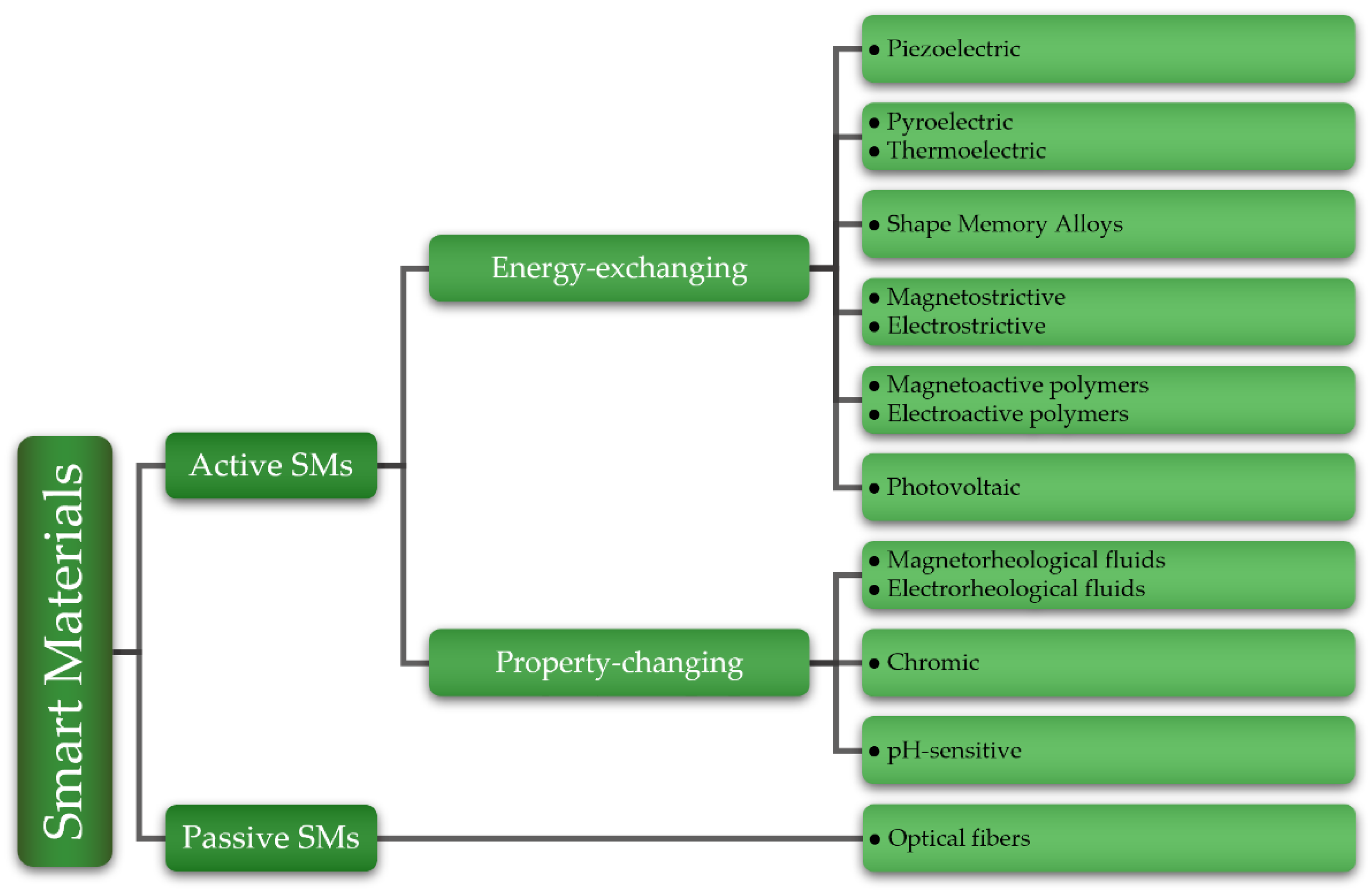
3.1. Classification of Smart Materials

SMs can be divided into two main classes, i.e., passive and active [1,3,5,6,8,11,17]. Figure 1 depicts a schematic diagram of their classification, which is based mainly on their characteristics and how they react to external stimuli. In the scientific literature, passive SMs are defined as being capable of transferring energy without transducing it [3,5,6,8]. The term “passive” also suggests that this category of materials needs a power supply and does not change their characteristics considerably when exposed to environmental changes. Although technically not SMs [11], optical fibers are considered passive SMs by many authors in the literature [1,3,6,8,18], therefore they were included in this review. Active SMs, on the other hand, can transduce energy [19], and they are further classified into two types. The first type of active SMs can change their properties when exposed to external stimuli, e.g., chromic materials can change their color when exposed to different types of outside stimuli [20], whereas the second type of active SMs can convert one form of energy, e.g., thermal, electrical, mechanical, or chemical, into another. Photovoltaic solar cells, which can convert solar energy into electricity [21], or piezoelectric and pyroelectric materials, which generate electricity when subjected to mechanical or thermal loads, are examples of this type of active SM. Furthermore, in the presence of an electric field, piezoelectric materials can produce mechanical strain and vice versa [22]. Shape memory alloys can be modified in shape, and their original shape restored by heating or cooling [23].
Another classification method for SMs is based on their reversibility and bidirectionality [11,24]. Some active SMs exhibit the ability to switch between input and output energy types. Many materials that deal with electricity conversion have this property, e.g., piezoelectric, pyroelectric, and thermoelectric materials, which can convert and reverse electricity into mechanical strain and temperature difference, respectively. Moreover, bidirectional materials can be used in a variety of other applications, such as the two-way shape memory effect, which allows shape memory alloys to be used to provide multiple or switchable outcomes, enabling the replacement of multi-part components with a single piece of material, or piezoelectric materials in self-sensing actuators, which combine their dual effects as a sensor and actuator simultaneously [25,26].

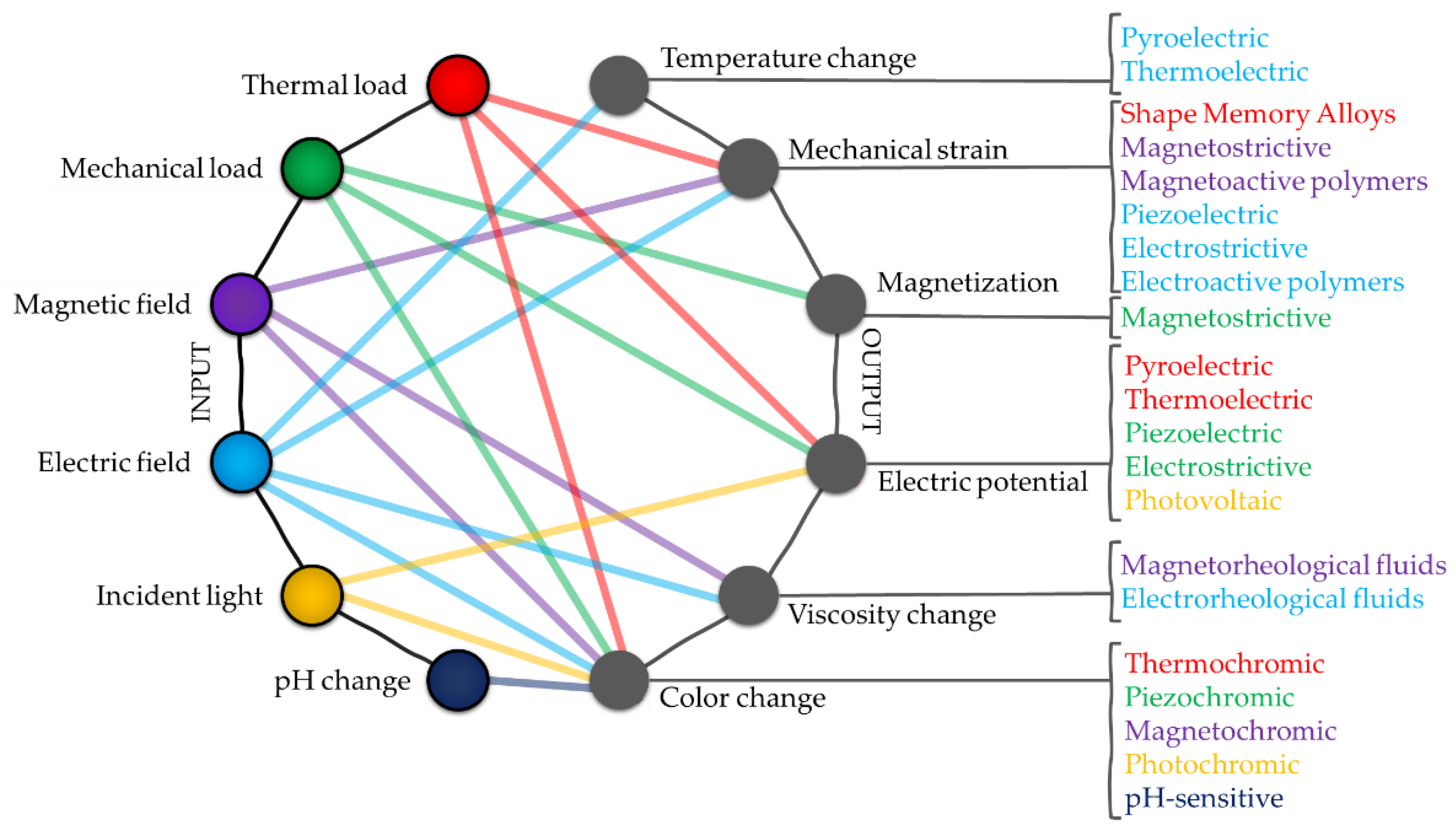
3.2. Types of Smart Materials

There are many different types of SMs, which can be divided by compound, e.g., organic or inorganic [27]; by material, e.g., metallic or polymeric [28,29]; or by state, e.g., solids, gels, or fluids [30]. Whether organic, metallic, or gel, generally all SMs are classified into types based on their behavior, depending on how they react to different external conditions, and the main properties that SMs exhibit which distinguish them from other materials are:
  • Transiency—SMs are capable of responding to multiple stimuli and existing in a variety of states;
  • Immediacy—SMs’ response time is usually quick, and they can respond in real-time;
  • Self-actuation—SMs’ inherent property and refers to the ability to change appearance and shape;
  • Selectivity—SMs reaction is distinct and predictable;
  • Directness—SMs action and reaction take place in the same place.
In the following section, the types of SMs used in biomedical force measurement systems are briefly discussed, while Table 1 lists an example of how several types of active SMs react to external stimuli of different origins, and Figure 2 shows how stimuli and responses are related.

3.2.1. Piezoelectric Materials

Piezoelectric materials are among the most common of all SMs. Piezoelectricity is a property of materials that can be seen as an electric charge or voltage generated by the application of mechanical loads or, in the opposite case, as a mechanical deformation brought on by the application of an electric field. These piezoelectric effects, discovered by Pierre and Jacques Curie between 1880 and 1881, were classified as “direct piezoelectric effect” and “converse piezoelectric effect”, respectively. The Curie brothers investigated the effect of mechanical pressure on electricity induction in some specific crystals, such as quartz, Rochelle salt, tourmaline, and cane sugar [32,33,34,35]. The direction of the applied mechanical load determines the polarization of the piezoelectric material; on the contrary, when an electric field is applied, the material has the ability to change its shape, allowing the energy to be released as a mechanical strain. Piezoelectricity is a property of many organic and inorganic materials, including ceramic and polymeric materials [34]. Among the most common piezoelectric materials, lead zirconate titanate (PZT), lead titanate, polyvinylidene fluoride (PVDF), lead magnesium niobate–lead titanate (PMN-PT), and barium titanate (BTO) can be found [36]. The piezoelectric material’s constitutive equations are expressed in many forms, but the two most used are [37]:
ε i j = C i j k l σ k l + d k i j E k ,
D i = d i k l σ k l + e i j E k ,
where the indexes represent various directions in the material coordinate system, εij denotes the strain tensor, Cijkl the elastic compliance matrix, σkl the stress tensor, dkij the matrix of piezoelectric coefficients, and Ek the electric field. The first term in Equation (1) indicates Hooke’s law, while the second one is the converse piezoelectric effect. Likewise, Di and eij indicate the electric flux density and the dielectric permittivity matrix, respectively. Generally, the electromechanical properties of an anisotropic piezoelectric continuum can be defined by 18 independent coefficients because of its symmetry. Furthermore, the linear piezoelectricity theory is based on hypotheses such as infinitesimal deformations, linear stress-strain relations, and stationary electric fields. Equations (1) and (2) can be expressed in alternate forms by considering the boundary conditions and including other variables, e.g., temperature effect [37]. Moreover, to this day, there are ongoing attempts to define more accurate analytical models that consider the nonlinearities of piezoelectric materials [38], since at low levels of applied electric field and stress, the linear model provides a reasonable approximation of the functional characteristics of piezoelectric materials, but it becomes progressively inaccurate as the electric field and stress levels increase.

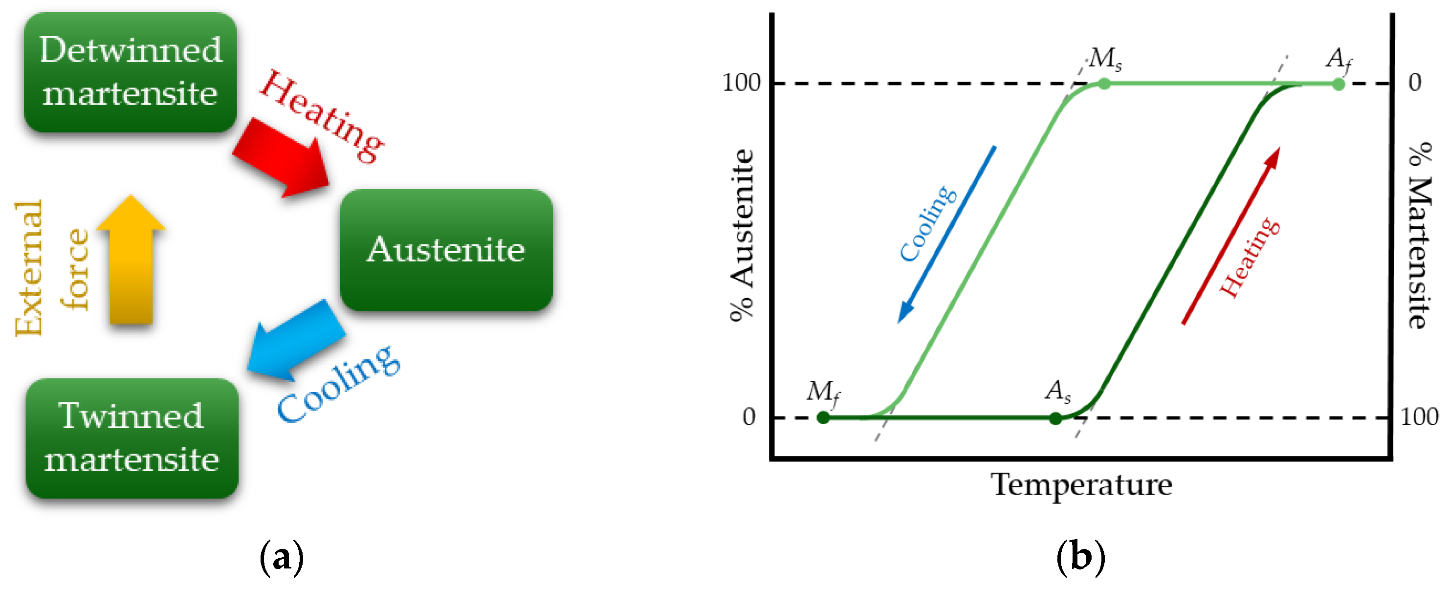
3.2.2. Shape Memory Alloys

Shape Memory Alloys (SMAs) are a class of metallic alloys that can be classified into two categories based on the type of stimuli they respond to, i.e., thermo-responsive and magneto-responsive [39]. The first type can be activated thermally by heating, and the second type reacts to static and oscillating magnetic fields. The underlying driving mechanism in both cases is the reversible martensitic transformation. In particular, thermo-responsive SMAs can be plastically deformed when subjected to a mechanical load below a certain temperature, and can revert to the original shape between two transformation phases (austenitic and martensitic) when heated above a certain temperature. The increase in temperature can be also induced by Joule effect when SMAs are powered electrically. In this case, they can be classified as three stage smart actuators (i.e., Joule effect to temperature variation to mechanical deformation). SMAs can exist in three different crystal structures, i.e., austenite, twinned martensite, and detwinned martensite (Figure 3a) [23]. At lower temperatures, the martensite phase is stable, while austenite is stable at higher temperatures. The thermoelastic transformation of martensite depends on two effects: the shape memory effect (SME) and superelasticity. Figure 3b shows the difference in transformation temperature from the martensitic to the austenitic phase. During cooling, Ms is the martensite starting temperature, and Mf represents the martensite final temperature. In the same way, As and Af indicate the austenite starting and final temperature, respectively [5]. The SME phenomenon occurs when the structure is heated or cooled to specific characteristic transition temperatures, and afterward, SMAs recover their original size and shape.
This effect is observed when the SMA temperature is below Mf and, when the alloy is in deformed martensite, it will regain its original shape by heating it above the Af temperature [23,40]. At higher temperatures, one-way SMAs only have one original shape, whereas two-way SMAs can have two recoverable shapes: one in the austenite phase and the other in the martensite phase. Regarding superelasticity, this property of SMAs allows the materials to resist large cyclic deformations without residual deformation and cover large elastic deformations (up to 8%) [6,40]. Superelasticity occurs at very high temperatures when there is a stable austenite structure. Historically, Ölander discovered shape recovery while researching Cadmium-Gold alloys in 1932 [15], and this phenomenon has since been observed in many other alloys. Among the most widespread, nickel-titanium alloys are one of the most effective and they are commercially available under the name Nitinol.

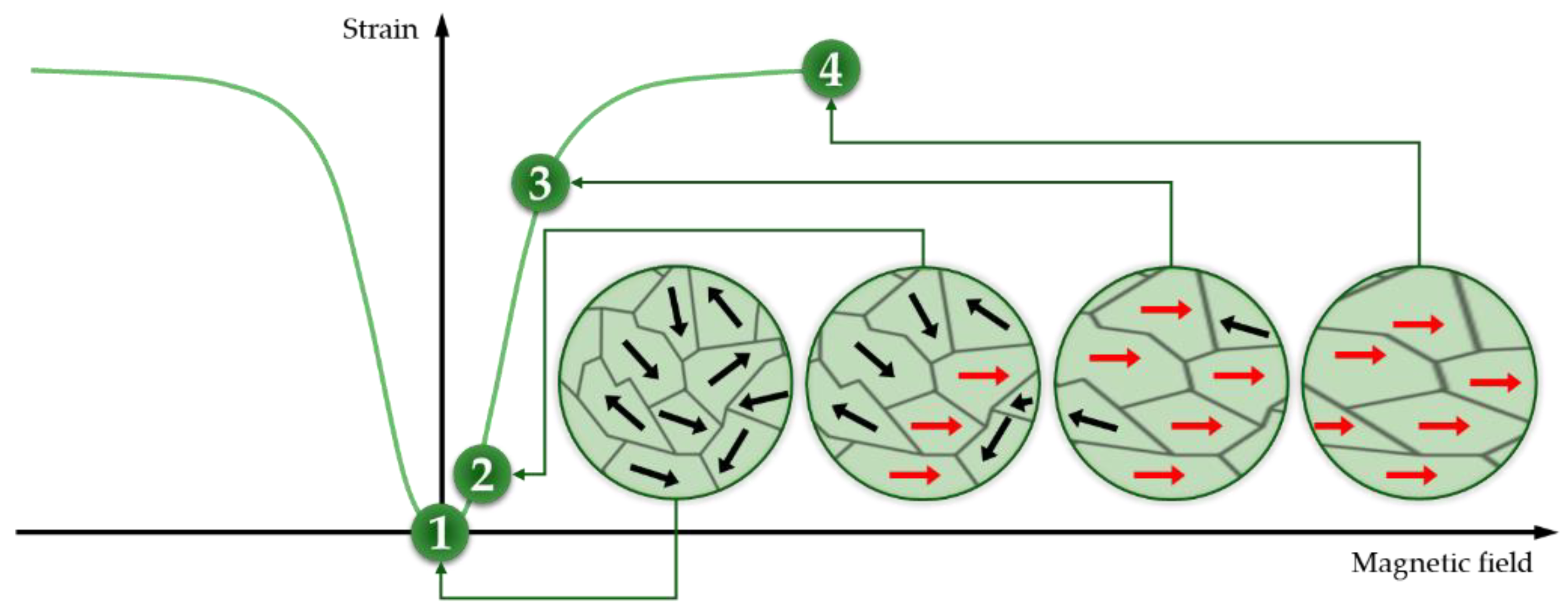
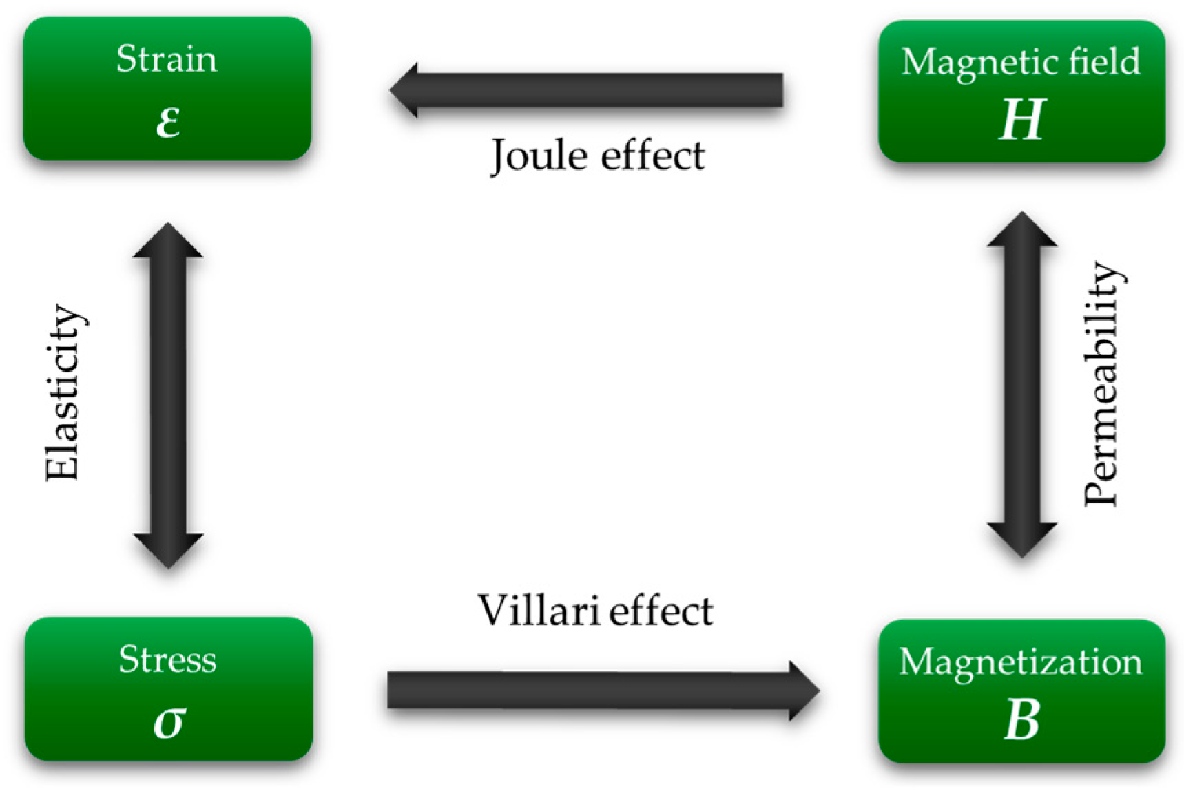
3.2.3. Magnetostrictive and Electrostrictive Materials

Magnetostrictive materials are able to convert energy between the magnetic and elastic states [1]. This phenomenon, known as magnetostriction, describes the alteration in physical dimensions that many magnetic materials show when their magnetization changes. The magnetostriction energy transformation process is bidirectional: from mechanical deformation to magnetization, and vice versa. These materials have complex behavior because of their frequency-dependent hysteresis and nonlinear properties. The material’s molecular dipoles and magnetic field boundaries rotate to align with the field as a magnetic field is applied. The material elongates or contracts as a result. Figure 4 shows a schematic representation of the deformation of a magnetostrictive material when a magnetic field is applied, and by way of illustration, four points along the curve are described:
  • Magnetic domains have a random orientation when no magnetic field is applied. Therefore, no change in size occurs;
  • By magnetizing, a small region of the magnetic domain is reoriented in the same direction as the magnetic field, and the strain starts to occur;
  • As the magnetization increases, the number of magnetic domains that align increases. Moreover, a linear relationship between the applied magnetic field and strain can be found (points 2 to 3);
  • When all magnetic domains align to the magnetic field, there is no further strain.
When subjected to magnetic fields or stresses, the behavior of a magnetostrictive material depends on different effects [41], as shown in Figure 5. The strain in magnetostrictive materials obtained by applying a magnetic field is known as the Joule effect. James Prescott Joule performed the first measurements of magnetostriction by quantifying the change in length of magnetized iron samples. The Joule effect can be described by the following equation [42]:
ε = C H σ + λ H ,
where CH is the elastic compliance coefficient matrix under constant field H, and λ indicates the magnetostrictive coefficient. In addition, that strain can produce a stress due to the material’s elasticity, which in turn can produce magnetization. The latter phenomenon is called the Villari effect, and it can be expressed as follows [43]:
B = λ σ + μ σ H ,
where B is the magnetic induction, and μσ is the pure linear magnetic permeability matrix at constant applied stress [44]. Finally, magnetized materials can produce magnetic fields because of their magnetic permeability. Iron alloys exhibiting cubic Laves phase and containing rare earth elements, such as samarium (SmFe2), terbium (TbFe2), or dysprosium (DyFe2), have the highest known magnetostriction. In particular, Terfenol-D (TbxDy1−xFe2) is one of the most commonly used engineering magnetostrictive material because of its large deformation at room temperature [41,45]. Terfenol-D is an alloy of terbium (Ter), iron (Fe), and dysprosium (-D), and its formulation was developed at the Naval Ordnance Laboratory (NOL) by a research group led by Arthur E. Clark [46]. Due to their high saturation magnetostriction, materials based on cobalt ferrite (CoFe2O4) are widely used in magnetostrictive applications, and they are an effective Terfenol-D substitution if rare-earth elements are not available [47].
Moving on to electrostrictive materials, the phenomenon that takes its name occurs when a material changes its size in response to an electric field. The ions are displaced from their initial positions when they are exposed to an electric field, increasing or decreasing their size. The principle behind electrostriction is similar to that seen in magnetostriction, with the difference being the nature of the applied external field, i.e., electric or magnetic. Moreover, electrostrictive materials are often grouped with piezoelectric ones; in fact, piezoelectric materials also have this property, and the electrostrictive effect can be classified as a linear piezoelectric effect contribution that is dependent on electric fields. As with piezoelectric materials and Equation (1), one of the fundamental equations for electrostrictive materials is:
ε i j = C i j k l σ k l + d k i j E k + M k l i j E k E l ,
Equation (5) is composed of three terms: firstly, Hooke’s law; then the converse piezoelectric effect; and finally, the electrostrictive effect. The latter depends on the components Mklij of the fourth rank tensor; those components indicate the electrostrictive coefficients [49,50]. However, since the piezoelectric effect occurs only in non-centrosymmetric materials, the two phenomena are theoretically independent. Conversely, the electrostrictive effect, which is characterized by an even rank tensor, is not symmetry-restricted and occurs in all materials, including amorphous ones. Thus, the strain on the applied electric field described by the electrostrictive effect has a nonlinear dependence [51]. While all dielectrics present electrostriction, relaxor ferroelectrics [52,53] are a class of ceramics that have extremely high electrostrictive coefficients, and among them the most common are lead lanthanum zirconate titanate (PLZT) [54,55], lead magnesium niobate (PMN) [50,56], and lead magnesium niobate-lead titanate (PMN-PT) [57].

3.2.4. Optical Fibers

Optical fibers are transparent and flexible fibers, usually made of plastic or glass, characterized by an inner diameter (core) in the order of micrometers [6,11,18]. They are commonly used to convey light between two ends and are widely employed in fiber-optic communications, where they allow transmission over larger distances and at higher bandwidths than electrical connections. Optical fibers are preferred to metal wires because they are able to carry signals with minimal loss and, in addition, they are immune to electromagnetic interference. The concept behind optical fibers, based on the guiding of light by the phenomenon of refraction, was discovered in the early 1840s by Babinet and Colladon. The light transmission in an optical fiber occurs by complete internal reflection if the transmitting fiber, also known as the core, is clad with a material that has a lower refractive index. Moreover, the transmission of light throughout a fiber via total internal reflection allows only specific modes of propagation, which are dependent on the diameter of the fiber and the wavelength of light utilized [58]. Optical fibers are used for several applications and, in addition to communication, lighting, and imaging, they are used as sensors. The principle of optical fiber gratings, in particular, is based on periodic changes in the refractive index along the core of optical fibers. Fiber gratings are classified into two main types: short and long-period gratings, e.g., short period gratings, also known as Fiber Bragg Gratings (FBGs), reflect specific wavelengths while transmitting all others. As a result, FBG can be used as an inline optical fiber to block specific wavelengths, making it suitable for sensing applications [59,60]. Optical fiber systems can also be based on interferometric techniques, which use the interference between two beams propagating through different optical paths of a single fiber or two different fibers. Optical fiber interferometers can be dived into four main categories: Sagnac, Mach-Zhnder, Michelson, and Fabry-Pérot interferometers [61].

4. Applications of Smart Materials

Nowadays, SMs play an important role in modern society and are progressively being employed in various fields of technology, including automotive and aerospace, robotics, civil engineering and construction, marine systems, and biomedical. According to a 2022 report [62], the worldwide SMs market reached a value of USD 47.36 billion and is continuously growing, with the expectation that it will reach a value of USD 92.48 billion by 2027. The increased use of SMs is due to technological evolution in several applications, e.g., actuators, sensors, shock absorption, vibration damping systems, shape control, structural integrity, automatic on/off switches, and operational maintenance, because of some unique properties of these materials. SMs are characterized by extreme flexibility of use and manufacturing. In fact, in addition to the more traditional methods for the production of systems based on SMs, new technologies based on rapid prototyping methods for the production of ever-smarter systems are increasingly growing [63,64,65]. In the following sections, examples of the main applications of SMs in the biomedical field will be illustrated, with a focus on systems actually implemented for force measurement.

Biomedical Field of Application

Due to their extreme flexibility, one of the most promising fields for SM application is the biomedical field, which is the field of interest of this review article. Applications in the biomedical field primarily focus on biomedical monitoring and measurement, biomedical information processing, and biomedical treatment. Based on the device application, a broad range of rigid and flexible materials are used to create biomedical systems that satisfy parameters, including biocompatibility, durability, stretchability, form factor, washability, sensitivity, selectivity, and self-healing property [66,67,68,69]. With SM-based devices, it is possible to carry out constant monitoring of human activities, which can help trace the evolution of a disease and, consequently, administer the necessary treatments. To do this, a wide variety of SMs offer multiple applications in the biomedical field, which can be divided into three main categories:
  • devices and systems for diagnostics and monitoring;
  • surgical instruments and therapeutic devices;
  • implants, prostheses, and rehabilitation devices.
Biocompatibility is a key feature because medical devices are composed of transducers that are in contact with human tissue and interact with biological substances [70]. In particular, piezoelectric materials are biocompatible, or can be made biocompatible after encapsulation. PZT’s biocompatibility must be investigated, primarily because the material includes lead, which is toxic to organisms. PVDF, on the other hand, is a suitable option for usage in surgical meshes and sutures due to its inertness, and its piezoelectricity makes it an appropriate material for wound healing [71]. As regards SMAs, because of their excellent biocompatibility, corrosion resistance, and kink resistance, Nitinol has a wide range of applications in medicine, particularly in orthodontics, drug delivery systems, self-expanding stents, implant devices, atrial occlusion devices, and ophthalmology [72]. Existing magnetostrictive materials for biomedical applications are currently limited. Terfenol-D has good magnetostrictive characteristics but restricted machinability and probable biotoxicity due to the high quantity of rare earth elements. Fe-Ga alloys, on the other hand, have demonstrated good extracellular and intracellular responsiveness, but their saturated magnetostriction is limited for giving effective mechanical stimulation [73]. Biocompatibility of optical fibers is determined by the type of material they are made of, e.g., ceramics, hydrogels, synthetic polymers, and natural materials that offer applications in the biomedical field ranging from optogenetic stimulation to surgery, phototherapy, biochemical sensing, and imaging [74].
Piezoelectric materials are used in diagnostic systems as ultrasonic transducers [75], but also as actuators for microdevices such as micropumps, microvalves, and microgrippers. The shape-memory effect of SMAs is also used for this type of application [76,77,78]. Piezoelectric materials are also used for tissue stimulation and tissue regeneration, as in the case of bone repair [79,80]. Piezoelectric materials, pyroelectric materials, and thermoelectric materials are used in energy harvesting systems for powering wearable or implantable devices [81]. Another application made available by piezoelectric and magnetostrictive materials is their use as biosensors for the detection of several types of viruses, including among the most recent applications in the detection of SARS-CoV-2 [82]. SMAs also offer multiple applications in the biomedical field; among the most widespread applications is their use in orthodontic and orthopedic prostheses, in hand motion devices for patients with reduced mobility and for the movement of atrophied muscles, but also as coronary, carotid, and femoral stents and as feedback devices in surgical instruments [83,84,85,86]. As soft gripper actuators, piezoelectric materials and SMAs are both used. SMAs have a slower response time than piezoelectric actuators, but these actuators, on the other hand, cannot deform as much as SMAs [87]. Delicate manipulation is frequently required for effective surgical procedures, but metallic grippers offer far from ideal pressure distribution. The soft nature of these devices allows for better force distribution, resulting in adaptive closure and gripping with self-limiting applied force, thus avoiding tissue damage [88]. Due to the flexibility provided by soft grippers, an exact measurement of applied force is not required for this application. Magnetostrictive materials are used in biomagnetic field measurement, wireless implantable devices, and mechanical stimulation of cells to control proliferation and functions [73]. Optical fibers have a wide range of biomedical uses, including robotic eye surgery, gastroscopy, colonoscopy, and flow monitoring in pulmonary ventilators [18,89,90].

5. Force Measurement for Biomedical Applications

Most therapeutic, surgical, and drug-delivery devices require a force change to function properly. The applied force by the device can be varied automatically by the actuation system, manually by an operator or directly by the patient. In micro- and macro-manipulation, there is a growing need to consider the interaction between the manipulated object and the manipulator [91]. As a result, embedding force-sensing technology into these devices could provide real-time force feedback and is a challenging target that can go a long way toward satisfying patient needs; in some situations, it is required for the application to carry out, such as biological tissue characterization and objects manipulation. Embedding force-sensing technology into a medical device requires a compromise between functionality and adaptability. Therefore, the issue to be resolved is determining the best force-sensing technology to employ in order to improve the device without introducing more burden to the end user. Traditional methods of force evaluation rely mainly on strain and displacement measurements, which can be accomplished with strain gauges and LVDT (Linear Variable Differential Transformer) or capacitive sensors, respectively. In particular, in the biomedical field, in situ forces are usually measured with strain gauge-based transducers [92]. Piezoelectric materials, on the other hand, can be considered conventional methods because they have been studied and implemented for many years. Many force measuring applications require both strain gauge and piezoelectric force transducers. The choice between them is determined by the application’s specifications. Piezoelectric sensors can provide good dynamic measurements, especially when compact size is required. While in heavy duty industrial applications, strain gauge transducers are more common. After presenting the main methods based on different types of SMs, their performance and main metrological characteristics, including measuring range, sensitivity, linearity, and accuracy, will be compared and resumed in tables.

5.1. Force Measurement Using Piezoelectric Materials

Piezoelectric materials are among the most popular SMs for force measurements, and among them, the most common are PZT and PVDF. Methods based on both the direct and inverse piezoelectric effect are used to make force measurements with these materials. Through the direct piezoelectric effect, it is possible to quantify the electrical charge produced by deformation due to the applied force and measure its magnitude. Conversely, methods based on the inverse piezoelectric effect require a power supply to oscillate the piezoelectric sensor. The effective mass and stiffness of the sensor structure determine resonance frequency, and when the sensor is deformed by an applied force, the stiffness varies proportionally. The force applied to the sensor not only charges the material but also affects other electrical characteristics, such as electrical impedance, and since piezoelectric materials can be thought of as capacitors, it is possible to evaluate the applied force by measuring changes in its capacitance. Finally, it is known that the applied force directly affects the decay time constant of piezoelectric sensors. As a result, it is also possible to estimate forces using piezoelectric sensor systems by measuring the decay time constant. Table 2 provides an overview of the main characteristics of different methods based on piezoelectric materials.

5.1.1. Electric Charge Measurement

By applying an external force on the crystal, the charge variation follows a proportionate relationship, as seen in Equation (2), and in the absence of external electric fields, the mathematical expression can be written as follows:
D i = d i k l σ k l ,
where Di is the electric displacement in i direction, dikl is the matrix of piezoelectric coefficients, and σkl the mechanical stress.
In 2005, Kim et al. [93] presented a superelastic alloy microgripper actuated by electromagnetic voice coil motors and equipped with a rectangular piezoelectric PVDF polymer as a force feedback sensor. In order to capture force signals at low frequencies (0.1 to 10 Hz), a commercial charge amplifier was used, and during their experiments, forces with a 1 Hz sinusoidal signal were applied to the sensor. The maximum force detected by the PVDF sensor was 13 mN for the task of optical fiber alignment, and 5 mN for tissue handling, with a sensitivity of 25.3 mV·N−1 and linearity of ±6.5%.
In 2008, Liu et al. [94] presented a PVDF sensor based on a cantilever beam structure, able to measure sub-micronewton forces. The sensor was characterized by a length of 25 mm, a width of 10 mm, and a thickness of 0.1 mm. The PVDF sensor was tested in the range of 0–3 µN, with a maximum deflection of the sensor probe tip of 1.05 µm, and its sensitivity was estimated at 0.112 V·µN−1.
In 2011, Wang et al. [95] presented a flexible piezoelectric force sensor based on PVDF fabrics. The sensor was produced using electrospinning technology, which allowed for the growth of PVDF nanofibers on an electrically grounded metal plate. In order to evaluate repeatability and dynamic sensitivity, the sensor was tested under forces with frequencies of 0.05, 0.1, 1, 5, 15, and 20 Hz. Tests were carried out with forces in the range of 3–5 N on eight different sample surfaces to optimize the electrospun PVDF fabrics, thus obtaining a maximum sensitivity of 42 mV·N−1.
Later that year, Xie et al. [96] presented a system for microforces measurement during the process of embryo-injection. The proposed system was composed of a cantilever beam structure, on which a PVDF film was adhesively bonded, and a transducer for the conversion of the output charge into a voltage signal. The PVDF force sensor was tested within a measurement range of 500 g, obtaining a force measurement range of up to 350–1500 µN depending on the cell and needle sizes, a sensitivity of 1–4.3 mV·µN−1.
In 2013, Ren et al. [97] presented a pressure sensor based on poly[(vinylidene fluoride)-co-trifluoroethylene] P(VDF-TrFE) nanofiber web, produced with electrospinning technology. The addition of an appropriate amount of TrFE can improve the crystallinity of the polymer. The sensor was composed of a layer of electrospun nanofiber web sandwiched between two plastic films. Tests were conducted with external forces at a frequency of 1 Hz on different sensors with a different VDF-TrFE ratio in order to evaluate which composition resulted in the sensor with the highest sensitivity. The maximum assessed sensitivity was equal to 60.5 mV·N−1 in the measurement range of 15–50 mN for the sensor with a 77/23 VDF-TrFE ratio. In order to assess the sensor reliability, the authors characterized its response depending on external forces with different frequencies, and the P(VDF-TrFE: 77/23) proved itself capable of sensing external forces up to 20 Hz. The study demonstrated that the sensors were reliable for dynamic forces measurement, thus offering promising applications in a variety of fields, especially in health monitoring.
In 2016, Yu et al. [98] presented a PVDF flexible tactile sensor array for 3-axis contact force distribution measurement. The device, consisting of an array of six tactile sensors in a 3 × 2 matrix configuration, was fabricated with five layers: the outer layers were made of polydimethylsiloxane (PDMS), while inside there was a PVDF film layer sandwiched between two aluminum electrode layers. The upper electrode for each tactile sensor was divided in four square regions, with an area of 1.5 × 1.5 mm2 each. By evaluating the charge amounts and polarities of each touch sensor, it was then possible to assess both the magnitude of the applied force and its direction. The sensor was tested by applying variable forces with a 20 Hz frequency along the three dimensions in the range of 0–1.5 N in the direction perpendicular to the layers (z-axis) and 0–0.5 N in parallel directions (x- and y-axes). The calibration experiments demonstrated a good linearity in force measurement, and in particular, nonlinearities of 2.45%, 2.37%, and 1.74% for the x-, y-, and z-axes, respectively, were estimated. As regard the sensitivities, they were estimated at 14.93 pC·N−1 for the x-axis, 14.92 pC·N−1 for the y-axis, and 6.62 pC·N−1 for the z-axis. Moreover, the sensor was proven to have a low coupling effect, good repeatability, and a frequency response ranging from 5 to 400 Hz.
Ting et al., in [99], presented a 3-axis force sensor made of a PVDF thin-film with a single layer. The proposed sensor with a single layer is not only cost-effective, but it can also be used in limited spaces. It was tested in two different configurations: in general electrode mode and using an interdigital electrode for horizontal-side polarization, in order to enhance the sensor’s sensitivity. The device was tested in both configurations by applying forces in the range of 0–6 N along the three orthogonal directions. It was estimated that the general electrode sensor had a sensitivity of 0.34 V·N−1, 0.37 V·N−1, and 0.41 V·N−1 for the x-, y-, and z-axes, respectively, while by using an interdigital electrode, the sensitivity in the x- and y-axes can be successfully raised to nearly equal the sensitivity in the z-axis, i.e., 0.41 V·N−1 for the x- and y-axes and 0.4 V·N−1 for the z-axis.
In 2017, Wei et al. [100] presented a force sensor in PVDF and macro fiber composite (MFC) films used as fixed-guided flexure beams in a multistage compound parallelogram mechanism. The device was designed to assist the microinjection of cells, and it was able to hold them stably in addition to carrying out the force measurement. To measure the voltages generated by the PVDF and MFC films, a charge amplifier was used. The experimental results demonstrated that the PVDF-MFC force sensor had a sensitivity of 1.23 mV·mN−1 and a measurement range of 100 mN.
Hosseini et al. [101] investigated the effect of different ratios of Multi-Walled Carbon Nanotube (MWCNT) and Cloisite 30B (OMMT) nanoclay on the electrospun PVDF nanocomposites’ performances. For testing the different samples of PVDF, a force between 5 and 6 N was applied, and a sensitivity of 8.8 ± 1.6 mV·N−1 was achieved for the PVDF conventional film sample, while electrospun samples achieved a sensitivity of 8.6 ± 1.2 mV·N−1 in the case of pure PVDF nanofibers, 10.9 ± 1.3 mV·N−1 for the 0.05 CNT/0.1 clay composition, 9.0 ± 1.6 mV·N−1 for the 0.075 CNT/0.075 clay composition, and 8.4 ± 0.9 mV·N−1 for the 0.1 CNT/0.05 clay composition, respectively. Thus, demonstrating how doping MWCNT/OMMT nanoparticles into the PVDF matrix combined with electrospinning technology can significantly improve the sensitivity of the PVDF piezo polymer. In particular, results revealed that the combination of MWCNT/OMMT doping into the PVDF matrix and electrospinning may considerably improve PVDF sensitivity; however, the effect of OMMT on improving sensitivity was greater than the effect of MWCNT.
In 2019, Li et al. [102] presented a PVDF film force sensor for steel ball cold heading machines. The sensor was composed of an under cover main structure and connected with the machine, an upper cover as a floating body where the pressure was applied during the cold heading process, and the PVDF film group, positioned between the two covers. The PVDF sensor was tested at six different loads in the range 550–640 N, and the results showed a sensitivity of 14.6 pC·N−1 with a nonlinear error of 0.197%.
In 2021, Chen et al. [103] presented an instrumented glove for acupuncture force sensing and finger gesture monitoring. The glove was equipped with two piezoelectric sensors placed on the first and second fingers (thumb and forefinger). Each sensor was composed of two outer plastic layers and a PVDF film sandwiched between two copper layers. The devices were tested in the main acupuncture tasks, i.e., twisting and lifting-thrusting phases, in the range of 0.33–1.27 N and 0.23–0.88 N, respectively, with a sensitivity of 0.14 mV·N−1 and 0.18 mV·N−1. The experimental outcomes showed that the glove can detect both normal and shear stress when acupuncturists manipulate needles.
Finally, Royandi et al. [104] designed and developed a prototype piezoelectric sensor for force measurement consisting of a PZT disk. The sensor was characterized by numerical simulations and experimental tests. The obtained results proved that the sensor was able to measure forces in the range 0–100 N, producing an output voltage from the amplifier circuit in the range 0–4 V, thus obtaining a sensitivity of 42 mV·N−1.
As a last remark, it is worth noting that in all the studies reviewed so far, force measurements were carried out under dynamic conditions since, unless particular solutions are made, it is very hard to carry out static measurements using the direct piezoelectric effect because of the decrease in charge due to the capacitive effect of the material.

5.1.2. Resonance Frequency Measurement

In 1996, Ngalamou et al. [105] presented an approach for static force measurement based on a piezoelectric resonator. The sensor was composed of a middle layer of 110 μm PVDF film between two brass electrodes with a 100 μm thickness, two 4 mm rubber sheets, and outer layers made of steel. When forces are applied to this resonator, the resonance frequency shifts. The observed frequency shift was caused mostly by the PVDF-brass interaction. Tests were carried out considering brass electrodes with different surface roughness, i.e., 1 μm, 3 μm, and 10 μm. Experimental results showed that the maximum sensitivity was calculated for the sensor with the 1-micron-thick electrodes and estimated to be 0.92 kHz·N−1 with a measurement range of 0–350 N and linearity of ±2.5%. On the other hand, with the 10-micron-thick electrodes, the maximum measurement range of 0–800 N was estimated, but at the same time it was characterized by the minimum sensitivity value of 0.26 kHz·N−1 and linearity of ± 7%.
In 2000, Gehin et al. [106] investigated a piezoelectric resonant sensor-based static force measurement method. The piezoelectric sensor was composed of a PZT disk, with a thin circular steel plate clamped between two aluminum rings as the framework. An alternating voltage was used to power the prototype sensor, and static stresses were delivered to the diaphragm via an aluminum tube mounted to the circular plate. The prestressed sensor’s resonance frequency (800 Hz) increased linearly as the applied force increased in the range of 0–17.7 N. The sensitivity was determined to be 6.6 Hz·N−1, with linearity of 3.5%. Due to the varied coefficients of thermal expansion and temperature dependency of elastic modulus for the sensor materials, a reasonably high temperature sensitivity (9 Hz·°C−1) was also observed.
In 2003, Barthod et al. [107] presented a piezoelectric resonant sensor with a double-ended tuning fork structure for force sensing applications. The sensor was composed of a thin circular plate, two beams, a tube, and two PZT elements. To reduce the temperature effect, the round plates and beams were fabricated of an Invar alloy with a thermal expansion coefficient close to that of PZT and, to prevent unequal loading effects, the beams were chemically cut directly into the circular plate. When a force was applied to the circular plate via the tube, the beams were likewise stressed, increasing the resonance frequency. The prototyped sensor’s experimental results demonstrated that the resonance frequency grew linearly over the tested force in the range 10.8–30 N. Sensitivity and linearity were determined to be 10.5 Hz·N−1 and 3.6%, respectively. In addition, it is worth noting that the temperature sensitivity was substantially lower at 0.3 Hz·°C−1 when compared to the standard diaphragm design sensor.
In 2017, Safour et al. [108] presented a piezoelectric resonant sensor for high static force sensing applications. For the experiments, a ring-shaped PZT specimen was designed, and it was compressed using a compression machine. According to preliminary experimental data, the resonance frequency increased nonlinearly as a function of the applied force. Lower spectrum quality was detected for forces greater than 500 N due to parasitic vibration modes on the main spectrum, which greatly reduced the force measurement range. The unwanted vibration modes were mostly produced by the fixing conditions at the contact surfaces. To remove this effect, a soft material-based coating, such as rubber or Polytetrafluoroethylene (PTFE), was placed on the ring-shaped PZT. The obtained results demonstrated improved sensor performance with increased linearity and the rejection of parasitic modes. The maximum force range and sensitivity were both estimated to be 1500 N and 1.9 Hz·N−1. Nevertheless, the quality factor decreased due to the layer’s substantial mechanical loss, implying that a suitable soft layer must be designed based on the required sensing applications.
In 2021, Volf et al. [109] presented a tactile sensor with a piezoelectric resonator as its main element. The sensor was composed of a piezoceramics PZK 850 with a thickness of 1 mm, width of 2 mm, and length of 2 mm. The authors investigated two different sensor designs with the same piezo element: in the first design the piezoelectric element was placed horizontally, in the second vertically. The two sensors were also composed of two brass electrodes and an elastic joint. Both sensors were tested with a lever mechanism that could withstand a maximum force of 50 N. Tests of the two sensors were carried out by connecting them to the same oscillator circuit, which allowed the force to be evaluated through the measurement of the voltage output to the circuit. In particular, a sensitivity of −2.32 mV·N−1 was assessed for the sensor with the horizontal PZK 850 element and −0.68 mV·N−1 for the sensor with the vertical piezoelectric element.
Wang et al. [110] developed a tri-axis static force sensor for ultrasonic tools using a PZT-QA ring-shaped element based on the evaluation of the compliance coefficient variation as a function of the applied force. The proposed sensor consisted of two PZT rings, one of which worked as a driver and the other as a sensor. The signals from the rings were connected via a flexible footprint circuit. Experimental tests were carried out by supplying the PZT driver with a peak-to-peak waveform of 20 V and a frequency of 312.7 kHz, and a pulley-guided steel wire rope was used to connect the weights to the PZT force sensor. The ultrasonic wave produced by the PZT actuator ring caused an output voltage to be produced in the sensor PZT ring. The force applied to the detector ring affected the material’s compliance coefficient, which altered the material’s resonance frequency. As a result, the PZT ring’s output voltage could be measured to evaluate external forces. The proposed sensor had a measurement range of ± 150 N, a sensitivity of 4.5 mV·N−1, and a resolution of 2.2 N. The obtained results confirmed that the sensor satisfies the applications of ultrasonic tools, e.g., the ultrasonic cutting of glass requires forces in the range 20 N to 100 N.

5.1.3. Electrical Impedance Measurement

In 2012, Lin et al. [111] presented a sensor for static force measurement using a piezoelectric resonant sensor’s electrical impedance measurement method. The sensor was composed of an unimorph cantilever beam with a PZT disk and an aluminum layer to benefit from simpler designs compared to double-ended tuning fork-type sensors. The top of the beam was subjected to static force, and compression forces were measured using a load cell. The experimental minimum and maximum force ranges were determined to be 0.5 N and 5 N, respectively, based on the linear response and the yield stress of the cantilever. According to the experimental results, the full-scale output of 10.1 × 10⁻⁵ Ω−1 in the force range of 0.5–5 N was evaluated, which corresponded to an electrical impedance of 9900 Ω and a force sensitivity of 2200 Ω·N−1. Furthermore, nonlinearity was determined to be 25.4%, with a hysteresis error of 9.2%.
In 2017, Purohit et al. [112] presented a method for precision conductance measurements of a radial mode piezo-resonator under various static loading conditions. The proposed system was composed of a PZT-5 ring disk with a thickness of 6 mm sandwiched between two butyl rubber layers. Conductance measurements of resonators were carried out for radial mode vibrations at frequencies ranging from 42 to 47 kHz and weights ranging from 0.5 to 4 kg. The authors stated that using this method, it was possible to achieve force measurements with an accuracy of 5%.
In 2020, Kim et al. [113] investigated a static force measurement system based on a custom-designed piezoelectric resonator. To take advantage of its high sensitivity to acoustic load, a face-shear mode PMN-PT single-crystal resonator was used as the sensing element in this study. In addition, the notion of a hyperelastic sensor layer was initially established and used to translate applied static force into acoustic load impedance. The elasticity of the sensor layer changed when a force was applied due to the cross-linking system of hyperelastic materials. As a result, the sensing layer’s acoustic impedance increased, because acoustic impedance was influenced by the elasticity and impedance. The acoustic load sensing approach, with face-shear mode piezoelectric resonators, allowed measuring the change in acoustic load impedance owing to elasticity change with high sensitivity. As the acoustic load impedance was directly proportional to the electrical impedance of the sensor, the static force could be evaluated by measuring the resonator’s electrical impedance. Normal forces ranging from 0.1 to 2 N were applied to the sensor for the force sensing test, and the electrical impedance shift of the sensor was detected through the top and bottom electrodes. It was proved that as applied normal forces increased, the electrical impedance rose linearly. The sensor’s sensitivity and accuracy were determined to be 51 Ω·N−1 and 50 mN (2.5%), respectively, in 0.1–2 N range.
Liu et al. in [114] developed a static force sensing method for smart skin applications by measuring electromechanical impedance with a piezoelectric resonator. A PZT plate with a resonance frequency of 900 kHz was placed in skin-like soft silicon rubber material to create a prototype sensor. Calibration weights were employed to provide static forces in the range of 0.5–2.5 N, and the impedance signal was measured using an impedance analyzer with frequency ranges of 0.1–3 MHz. A tactile index was employed as a diagnostic approach that compared average impedance values in order to eliminate the noise effect. Experimental results revealed that the index value grew continuously as the static force increased, and the sensitivity was found to be 1.8% N−1 with a resolution of 0.5 N.

5.1.4. Capacitance Measurement

In 2007, Sekalski et al. [115] investigated a static force sensing method utilizing capacitance measurements with a stacked piezoelectric resonator. For force sensing studies, a commercial PZT piezostack was employed, and tests were carried out by applying normal forces ranging from 730 N to 4 kN. The sensor showed an increase in its capacitance as a function of the force applied, with a sensitivity of 25 nF·kN−1 and a repeatability of ±5%. It was proven that the behavior of the sensor varied as a function of the applied load and, for loads greater than 500 N, the capacitance varied linearly with the force, whereas for loads less than 100 N, there was a nonlinear relationship. This was thought to be due to the piezostack’s high elastic modulus, which made a change in capacitance difficult when small forces were applied. On the other hand, because of its linearity and wide measurement range, the capacitance measurement method employing the piezostack demonstrated potential for large static force sensing applications.

5.1.5. Decay Time Measurement

In 2006, Ozeri et al. [116] presented a static force sensing approach based on the piezoelectric sensor’s decay time constant measurement. The sensor was composed of a disk-shaped PZT element with a 70 kHz resonance frequency sandwiched between two natural rubber layers. The sensor was tested by supplying it with a sinusoidal signal for the excitation and by applying static forces in the range 14.1–141.3 N. After the excitation phase, the current began to decrease exponentially, and the change in current was measured to evaluate the decay time constant. Since the decay time constant directly represented the amount of change in the applied force, it could be used to effectively measure static forces. Nevertheless, this study demonstrated that the decay time decreased nonlinearly as the applied static force increased.

5.2. Force Measurement Using Shape Memory Effect

Unlike piezoelectric materials, studies and patents in the literature on force sensing systems using SMAs are limited to just a few; this may be due mainly to the instability of SMAs under cyclic loading. In particular, the correlation between dislocation slip and martensitic transformation can be utilized to explain the accumulation of plastic stresses, the subsequent redistribution of internal stress, and, ultimately, the instability of cyclic deformation of NiTiNOL. Furthermore, environmental variables, particularly ambient temperature and loading speed, have an impact on instabilities [39,117]. The shape memory effect of SMAs, in which a change in electrical resistance causes or is followed by deformation in response to an applied force, was not addressed for sensors design but was investigated in the literature for the creation of self-sensing actuators. The key benefit of this sensor is that the bending element does not have to necessarily be a cantilever beam; with the right design, any device that can function as a bias, like a spring, may be made to act as a bending. This characteristic allows SMA-based sensors to be easily integrated into any mechatronic system with a simple and appropriate design. SMAs, on the other hand, display hysteresis and exhibit extremely nonlinear behavior. Table 3 summarizes the main characteristics of SMA-based force sensing methods.
In 2010 Lan et al. [118] proposed a method for self-sensing force control of actuators based on SMA wires. Both strain and resistance change of the shape-memory material were measured in order to evaluate the force. To compensate for hysteresis inaccuracies, the resistance curves could be altered by enough pretension force to display very small hysteresis gaps. It was demonstrated that the strain-to-resistance self-sensing paradigm for nonlinear flexure was independent of external loading circumstances. The experimental setup was constituted by a V-shaped Flexinol® wire and a spring that applied a preload to the system, often a bias spring, which was required to recover the detwinned martensite and, as a result, improve the linear behavior and hysteresis of the SMA wire. In addition, the system included two transducers that compared the applied force and strain obtained by the actuator, a load cell and a linear variable differential transformer, respectively. Three Flexinol® wires with different diameters were investigated: 100 µm, 125 µm, and 200 µm. During the testing phase, forces in the 1.7–4.67 N range were applied to the 125 µm thick wire. Since the hysteresis curve was affected by the pretension force as well as the diameter and length of the wire, each wire required a specific analytical model. The authors also implemented this technique in a gripper that was specifically designed to have the morphology and articulation patterns of a human finger. The gripper was made up of three fingers with a total length of 20 mm each, and when the fingers deflected 7.2 mm, the gripper could apply and sense a force of 1.05 N.
In 2017, Ruth et al. [119] developed a load cell that used an SMA wire as a secondary transducer connected between the free and fixed ends of a cantilever beam. Phase transformation caused an increase in electrical resistance in SMAs. The relevance lies in the fact that the relationship between the force applied to the sensor and the associated electrical resistance of the transducer was found to be linear over the operational range, even if SMAs exhibited hysteresis and were highly nonlinear. As a result, the design of the mechanical components of the SMA-based sensor was critical to its linear operation. The mechanical design of the deflection provided reverse hysteresis correction in this scenario. The proposed method involved a Wheatstone bridge circuit, in which the SMA wire was connected in a quarter-bridge configuration. Therefore, when a load was applied, the deflection modified the SMA’s electrical resistance in accordance with the load. A horizontal cantilever beam of 15 cm in length was attached to a vertical support, and the wire was 35 cm long and 150 µm in diameter. The resistance of the SMA wire attached to the free end of the beam changed as follows:
Δ R R = 0.1 1 + 2 ν l 3 3 E I L F ,
where ΔR and R denote the change in resistance and resistance of the SMA wire, respectively, ν denotes the Poisson’s modulus, l the length of the beam, E is its Young’s modulus, I is its moment of inertia, L the length of the SMA wire, and F the force applied to the beam. The coefficient 0.1 takes into account the ratio between the beam and the wire deflection. The sensor had a sensitivity of 0.01 V·N−1, linearity of 0.1%, hysteresis of 0.2%, and repeatability of 95.33% in the 0–10 N force range, according to experimental results. The system could measure 0.294 N of force as the lowest force value. Furthermore, the sensor was tested with dynamic loads, and a bandwidth of 10 Hz was determined.
In 2022, Mozhi et al. [120] proposed a force sensor based on SMA wires similar to the one described above, but the operating principle differs between the two systems: in the first one, the SMA wire was employed as a strain gauge and the force was evaluated by measuring the wire’s change in resistance; in this study, force evaluation was carried out by detecting the resonant frequency shift of the device after a force was applied, setting up an SMA-based resonant load cell. The proposed system was composed of an embedded beam, an SMA wire attached to the free end of the beam, and a dead mass. SMA wire was activated to function both as the self-sensor and the vibration inducer of the sensing system. The dead mass value must be adequate to retract the SMA into a deformed condition and provide deformation to the SMA wire during its martensitic phase, allowing for ongoing oscillations. A 15 cm length of 150 µm diameter Flexinol® wire was employed. The prototyped system was designed for a sensing range of 0.785–2.45 N and a sensitivity of 0.8 Hz·N−1.

5.3. Force Measurement Using Magnetostrictive Materials

The inverse magnetostrictive effect, i.e., the Villari effect, is the operating principle underpinning magnetostrictive force sensors. In particular, the magnetic permeability of a material changes as a result of external forces. Galfenol (Fe-Ga), Terfenol-D (TbDyFe), and Fe-Ni alloys are among the most commonly used magnetostrictive materials for force sensors. Table 4 outlines the main characteristics of the described methods.
In 2007, Baudendistel et al. [121] presented a novel magnetostrictive force sensor based on the Villari effect. The proposed sensor was made up of a magnetostrictive inner ring with two grooves cut into the outside surface. A press-fit outer ring made of magnetostrictive material was placed around the inner ring after a single wire was wrapped several times clockwise around the upper groove. When an alternating current was supplied through the wire, the system worked similarly to a self-inductance system, in which the material’s permeability affects the electrical impedance of the wire and, when a load was applied, the permeability and hence the impedance changed, allowing a measurement to be made. The sensor was heated from 20 °C to 140 °C before being cooled to room temperature. Forces ranging from 100 N to 21,000 N were applied as it attained steady-state temperatures along the route. With forces greater than 500 N, the measurement error was less than 4%, but it increased up to 14% when the applied load approached zero. Force sensors frequently experience low-force errors, which can typically be overcome by preloading them in order to avoid the low-force region.
In 2011, Jia et al. developed static [122] and dynamic [123] force sensors using giant magnetostrictive material with the aim of optimizing the sensitivity. At room temperature, giant magnetostrictive materials exhibit magnetostrictive coefficients that are 100–1000 times greater than those of typical magnetostrictive materials. The variation in magnetic flux density can be used to calculate static force. The magnetic flux density, on the other hand, changes dynamically under the action of dynamic forces. Then, using the Faraday effect, an induced voltage is generated in the pickup coil, and the dynamic force is detected by the induced voltage. The giant magnetostrictive force sensor evaluates static force using an integrated linear Hall sensor that measures a magnetic flux density proportional to the variation of magnetic flux density in the giant magnetostrictive material rod as a function of the external force. Terfenol-D was the material used in the sensor, with a length of 44 mm, a diameter of 12 mm, and a pickup coil with 1000 turns. Forces in the range 0–1000 N were applied in increments of 25 N, and the sensor’s sensitivity was estimated to be −0.4 mV·N−1.
In 2015, Ghodsi et al. [124] investigated a force sensor based on a giant magnetostrictive material. The sensor was made up of three major components: a Terfenol-D rod that was deformed by an external force, an excitation coil, and a Hall effect sensor. During the experimental tests, the applied force was made to vary from 0 N to 981 N in 11 steps and then lowered in the same manner. The second parameter was the electrical current through the excitation coil, which was increased in 10 increments from 0.1 A to 1 A. Experiment results showed that the sensor had the highest linearity and sensitivity for a current of 0.8 A. The proposed magnetostrictive force sensor could work in optimal conditions in terms of sensitivity and linearity, with a sensibility of 0.51 mV·N−1 and a maximum non-linearity of 2.8% in the measurement range of 98.1–981 N.
In 2019, Li et al. [125] presented a novel magnetostrictive tactile sensor based on the Villari effect. Aside from the contact conditions between the object and the manipulator, the tactile sensor could properly categorize, identify, and operate objects through the measurement of force and stiffness of manipulated objects. The sensor was made up as follows: a cantilever beam in Galfenol, a typical magnetostrictive material with good durability and low hysteresis; a Hall sensor; and two permanent magnets that produced an axial bias magnetic field for the Galfenol cantilever beam. The results revealed that the relationship between output voltage and force was linear in the 0–5 N range. Within this range, the force was measured with a sensitivity of 114 mV·N−1, a resolution of 0.07 N, and linearity of 3%. Furthermore, dynamic tests were performed, and the results demonstrated that the magnetostrictive tactile sensor had a good response and good sensing accuracy to dynamic forces with frequencies ranging from 2 to 4 Hz.
The same group of researchers presented another tactile sensor for object recognition based on the inverse magnetostrictive effect [126]. The tactile sensor array was constituted by Galfenol wires, a ring permanent magnet, contacts, a skeleton, a stiff base, a column, and Hall sensors. Galfenol wires measured 0.8 mm in diameter and 16 mm in length. The sensor had a sensitivity of 48.07 mV·N−1 and could measure forces ranging from 0 to 2 N.
In 2020, Weng et al. [127] developed a magnetostrictive tactile sensor array based on permanent magnets, Fe-Ga wires, and Hall sensors to measure static and dynamic forces, as well as sample stiffness. A weight was attached to the tip of the sensor unit to generate the static excitation force. A linear motor driven by a sinusoidal signal generated the dynamic excitation force. The tactile sensor unit had a force measurement range of 0 to 3 N and a sensitivity of 126 mV·N−1. In addition, four sensors were installed on a robotic hand for sensor array validation, and four different materials were employed for stiffness assessment. The results showed that the stiffness measurement error was less than 8.3%.
Yu et al. [128] proposed a magnetostrictive micro force sensor with a signal acquisition system designed for Android and Arduino platforms in order to reach out to popular mobile terminal. The main components of the micro force sensor were the transmission rod, soft iron shell, induction coil, permanent magnet, yoke, and Galfenol film, which had a 15 mm diameter and 0.35 mm thickness. A 0.5 N increase in external force was applied from 0 to 10 N for the sensor calibration. The sensor had good linearity with increasing external force, especially in the range of 3 to 10 N, a sensitivity of 0.154 mV·N−1 and a repeatability of 1.07%.
Shu et al. [129] presented an impact force sensor consisting of an electromagnet, magnetic circuit, cantilevered Fe-Ga alloy beam, and pickup coil. The voltage on the pickup coil was proportional to the impact force imparted to the beam’s free end. Three alternative cantilever beam geometries, including a rectangular beam, a uniform I-beam, and a tapered I-beam, were compared in this study. During the tests, impact forces ranging from 0 to 50 N were applied using an impact hammer. Results showed that the sensitivity was nonlinear, and it was particularly low for impact forces less than 20 N. This poor sensitivity zone could be avoided by precompressing the cantilever beam. The experimental results demonstrated that the maximum sensitivity for the tapered I-beam was 2.7 mT·N−1, which was at least 13.5 times higher than the rod sensitivity.
In 2022, Mirzamohamadi et al. [130] introduced a contactless hybrid static magnetostrictive force-torque sensor using Galfenol as the sensitive element. The sensor was made up of connecting rods that held coils together and an external sensor body made of extra-low carbon iron as a magnetic coupler. The magnetic field was generated by sixteen exciting coils connected by 40 turns on connecting rods. Axial force measurement required the passage of magnetic flux in the axial direction through the magnetostrictive material while stimulating opposing rods in the longitude direction. When measuring torsional load, the coils should be stimulated at a 45° angle to the axial direction of the rod. It was proven that when the sensor was measuring axial load, the torsional load had no effect on the sensor’s response. On the other hand, when the sensor was configured to measure torsional load, the axial load had a small effect (approximately 3%) on the output voltage. The sensor had its maximum sensitivity at 2 A and 500 Hz. Under ideal conditions, the sensor’s maximum sensitivity was 0.075 mV·N−1 and 2.24 mV·N−1m−1 for axial and torsional load measurements in the ranges 196–3400 N and 5–20 Nm, respectively. In axial and torsional load measurements, the maximum linearity error was 3.75% and 3.8%, respectively. The repeatability of the sensor was evaluated at 2.11% for axial load measurements and 2.2% for torsional load measurements.

5.4. Force Measurement Using Optical Fibers

Historically, optical fibers were widely used in the telecommunications industry and in the biomedical field, in which they allowed illumination inside the organs during endoscopic procedures. Over time, the same technology allowed carrying out other tasks and created transducers for tracking parameters of interest, for both diagnostic and therapeutic applications, as well as innovative methods for force measurement. Force measurements with fiber-optic-based devices are primarily based on two operating principles: FBG and interferometric sensors. When a fiber optic, which houses an FBG, is interrogated with polychromatic radiation, only a small range of wavelengths is reflected by the FBG. The central wavelength of such a range, known as the Bragg wavelength, can be described as a function of the core’s effective refraction index and the grating’s spatial period. FBG technology enables the fabrication of sensors with good metrological properties, such as high accuracy, wide bandwidth, wide dynamic range, and high strain and temperature sensitivity. However, to determine the wavelength of the reflected light, the measurement chain must use expensive equipment. In terms of interferometric fiber optic force sensors, they are mainly based on Fabry-Pérot interferometers (FPIs). In general, a Fabry-Pérot interferometer is made up of two parallel reflecting surfaces separated by a specific distance. Interference arises as a result of multiple superpositions of both reflected and transmitted beams on two parallel surfaces. Table 5 outlines the main characteristics of optical fiber-based force measurement systems.
In 2011, Song et al. [131] developed an optical FBG force sensor that could be used in minimally invasive robotic surgery. Eight FBGs were investigated in this study to assess the strains of a load cell. Four of them were utilized to measure the force on the tooltip, while the remaining four FBGs were not impacted by any force since they served for temperature compensation. According to experimental results, the sensor had a measurement range of up to 10 N, a measurement error of less than 0.1 N, and a resolution of 0.05 N.
In 2012, Liu et al. [132] proposed a miniature fiber-optic force sensor for vitreoretinal surgery based on low-coherence Fabry-Pérot interferometry. The sensor was made up of three lead-in single-mode fibers with a cladding diameter of 125 µm. Three FPIs were used for the simultaneous acquisition of data from three separate channels, allowing for the force measurement in three dimensions, with components both parallel and perpendicular to the tool shaft. The flexure deformed proportionally to the applied force, causing changes in the lengths of the FPI cavities that were utilized for the force computation. Testing weights were mounted to the force sensor in the axial force calibration experiment. Each testing weight was 0.897 ± 0.005 mN, and for each test, a different number of weights were added to the sensor, yielding forces ranging from 5 to ~18 mN. The experimental results show a maximum sensitivity of 43.2 nm·mN−1.
In 2013, Moerman et al. [133] presented a computer-controlled soft-tissue indentor equipped with an optical FBG force sensor. The device was designed for tissue characterization, and the force sensor was installed in the indentor head’s piston shaft. The FBG for force measurement and calibration revealed that force difference percentages were lower than 3.1% for forces in the range 0–15 N, with a maximum total force difference magnitude of 0.043 N. When forces greater than 1 N were taken into account, the maximum force difference percentage dropped to 1.2%.
In 2013, Polygerinos et al. [134] presented the design and testing of a triaxial force sensor based on reflecting light intensity modulation that could be used in cardiac ablation procedures. Fast prototyping processes offer a low-cost production alternative for the sensor design. The proposed catheter force sensor was designed to be inserted into the heart’s blood vessels and chambers; therefore the development of a liquid-tight sensor was needed. The sensor consisted of three single optical fibers and a flexure-mounted reflector that could move freely in all directions. The sensor had a measurement range of 0–0.5 N, a resolution of less than 0.01 N, a measurement accuracy of 6%, and linearity of 4%. The sensitivity was evaluated in three directions and expressed as a function of the output normalized voltage; it was equal to 1 N−1 for the x- and y-axes and 0.5 N−1 for the z-axis.
In 2014, He et al. [135] presented a novel three-degrees-of-freedom force sensing pick instrument for vitreoretinal surgery based on FBG sensors. The sensor was made up of three FBGs attached longitudinally along the instrument shaft at 120° intervals and a fourth inner FBG for the measurement of the strain caused by axial forces. The authors also presented a hybrid force computation algorithm for the estimation of transverse and axial forces using a linear model and a second-order Bernstein polynomial, respectively. In order to measure forces applied to the three-degrees-of-freedom force sensing device, a calibration weight of approximately 21 mN was used. The experimental results revealed a measurement range of ±20 mN, a resolution of 0.08 mN for the x- and y-axes, and maximum errors of 1.2 mN and 0.9 mN, respectively. In terms of the z-axis, tensile forces had a measurement range of 0–20 mN, a resolution of 0.49 mN, and a maximum error of 3.5 mN, while compression forces had a measurement range of −10–0 mN, a resolution of 0.41 mN, and a maximum error of 3.2 mN.
Saccomandi et al. [136] presented the design and characterization of a force sensor based on an FBG. The proposed sensor was based on a sensing element made up of a fiber optic and two FBGs reflecting two distinct Bragg peaks. Two alternative prototypes were developed to assess the sensor’s performance: only one configuration had the fiber encapsulated in a PDMS layer. The latter exhibited a linear response across the entire measurement range of 0–4200 mN. Nonetheless, there was a minor asymmetry in the linear decline of FBG outputs when force was applied. The cause was most likely PDMS inhomogeneity, and sensitivity values of −0.07 nm·N−1 and −0.110 nm·N−1 were evaluated, respectively. On the other hand, the sensor without PDMS had a non-linear response in the measurement range of up to 250 mN, but it had a higher sensitivity of 6.8 nm·N−1. Further tests were performed on the configuration without PDMS by applying force to the center of one FBG. Experimental results demonstrated that the output from the differential configuration was linearly proportional to the applied force over the entire calibration range of 0–250 mN, but the main disadvantage of this method was the reduced sensitivity (0.27 nm·N−1).
In 2016, Bützer et al. [137] presented the design and characterization of a low-cost, 3D-printed grip force sensor, based on a commercial intensity-based fiber-optic sensor. The device was made up of a compliant monobloc frame with flexible hinges that converted grip force into a linear displacement measured by a fiber-optic sensor. Two fiber-optic channels could be found on the sensor head and cable. The first channel emitted light, which was reflected on the mirror mounted on the center bar of the compliant construction, while the second channel gathered a fraction of the reflected light. The compliant structure was composed of polylactic acid (PLA) manufactured using a fused filament fabrication process. PLA is a biodegradable thermoplastic material, compatible with magnetic resonance imaging systems. The device was tested using two different protocols for force ranges of up to 800 and 500 N, respectively. The relative nonrepeatability and relative hysteresis were both less than 1% for both force ranges, and the accuracy was 5.99% for 800 N and 1.57% for 500 N. Furthermore, the sensitivity for 800 N was somewhat lower, at 0.843 ± 0.003 mV·N−1 versus 0.978 ± 0.005 mV·N−1 for 500 N.
In 2017, Al-Mai et al. [138] developed a low-cost, compliant 3-axes fiber-optic force sensor with an adjustable measurement range able to measure normal and shear forces simultaneously. The prototype was designed and constructed as a single sensor unit that could be used in a variety of biomedical applications, such as shoe insoles, collision detection, and human-machine interface. The sensor consisted of three reflective surfaces for each sensor, located in the center of a square rigid aluminum plate, and six optical fibers: two optical fibers for each direction, i.e., x-, y-, and z-axes, one transmitting and one receiving fiber. To properly fix and place the fibers into the device, three plastic holders made of Acrylonitrile Butadiene-Styrene (ABS) material were 3D printed. The prototype was tested by applying forces ranging from 0 to 140 N along the x- and y-axes, as well as normal forces ranging from 0 to 1000 N.
Shin et al. [139] proposed a miniaturized fiber-optic tri-axial force sensor based on FBG. The FBG force sensor developed in this work consisted of two main parts: a flexure tip and three FBG optical fibers mounted along the flexure at 120° intervals to measure 3-axes forces. In order to carry out a characterization, increasing forces in 9.8 mN increments between 98 and 490 mN were applied to the FBG force sensor.
In 2020, Lv et al. [140] presented a novel FBG-based palpation force sensor for investigating tissue abnormalities during minimally invasive surgery. This sensor consisted primarily of a force-sensitive flexure and a suspended optical fiber inscribed with an FBG element, as well as a threaded contact head and a sensor holder connector. The flexure design was developed and prototyped utilizing a rigid-body replacement method using the configuration synthesis of Sarrus linkage. During the static force calibration trials, axial forces in the range of 0–5 N were applied at 0.5 N intervals. The axial sensitivity was evaluated at 392 pm·N−1, with a resolution of 2.55 mN and linearity error of 0.97%.

6. Discussion

In this review, recent progress in SM-based force measurement methods is systematically summarized. A survey of the challenges in characterization, fabrication, and reliability is presented. Among all SMs, only four types are used for force measurement; in particular, the methods presented in this review are based on systems using piezoelectric materials, SMAs, magnetostrictive materials, and optical fibers. Through numerical and experimental efforts, some unique characteristics have been highlighted and compared for force measurement methods based on the aforementioned materials. The results obtained from several studies in the literature highlight that the presented solutions for force measurement cover many different measurements ranging from a few micronewtons, i.e., 3 µN, to kilonewtons, i.e., 21 kN, thus offering a wide range of possible applications in the biomedical field, ranging from micromanipulation and minimally invasive surgery techniques to the implementation of sensors for rehabilitation systems. Force measurement systems based on piezoelectric materials are the most investigated in the literature and can measure forces ranging from 3 µN to 4 kN using five principles: electric charges, resonant frequency, electric impedance, capacitance, and decay time measurement.
There are always specific objectives to be met when it comes to comparing different materials. Typically, it is possible to represent these goals using one or more performance indices, while material properties can be presented in various charts [141]. However, it should be noted that not all objectives can be represented in performance indices, and there are no unified standards that fit all SMs considered in this overview. Figure 6 depicts qualitatively some of the metrological properties, i.e., accuracy and sensitivity, of the SM-based systems discussed in the previous sections. The different materials are distinguished by color, and Figure 6a shows the accuracy expressed as the percentage of the maximum value of the force measurement range.
Sensitivity, as shown in the tables in Section 5, is affected by the operating principle of each type of SM and by the measurement chain reported in the various research studies. In Figure 6b, only the SM-based systems with sensitivity expressed as V·N−1 were considered for peer comparison.
SMA-based systems are among the least utilized materials for force measurement, and all of the examples given use NiTiNOL wires and are capable of monitoring forces ranging from 0.3 to 10 N. The presence of few systems used for force measurement based on SMAs could be related to the instability of these materials under cyclic loading. Furthermore, environmental variables, specifically ambient temperature and loading speed, influence the instability. Moving to systems based on magnetostrictive materials, these are capable of measuring forces ranging from a minimum of 2 N to a maximum of 21 kN. Lastly, force measurement devices based on optical fibers can measure forces ranging from 5 mN to 1 kN. Table 6 shows an overview of the measurement ranges of the systems based on the four types of SM presented above. In particular, the table highlights how many orders of magnitude each system is capable of measuring from a qualitative point of view. The force measurement range of the compared systems determines the field of application in which they are used.
Table 7 indicates the actual application ranges for which the systems mentioned in previous sections were employed or specifically designed. The applications listed in Table 7 range from operations requiring force on the scale of micronewtons, e.g., micromanipulation, robot-assisted microinjection, and minimally invasive surgery, to force on the order of kilonewtons, e.g., weight measurement and impact force or collision sensors. It should also be noted that not all the applications mentioned are related to the biomedical field, e.g., cold heading monitoring or car brake systems, but since they are compatible with the other described methods in terms of measurement range and operating principle, they might also be utilized in biomedical applications. It is worth noting that hybrid SM-based systems can also be found in the literature, e.g., hybrid piezoelectric actuators [142]. These systems can sense more than one stimulus and react with one single output, thus increasing the range of applications.
Although the results presented so far show how different methods can measure the same range of force, each of the SMs considered is characterized by its own strengths and weaknesses. Table 8 summarizes the main advantages and drawbacks of the SM-based methods. The table shows that some of the advantages of the abovementioned systems condition their potential applications, such as in the case of piezoelectric materials, whose miniaturization would allow the measurement of micro-forces for MEMS systems. In addition, the methods presented are based on biocompatible systems and may be used in applications where metallic materials are not permitted, as in the case of systems based on optical fibers, which are compatible with MRI systems.
Furthermore, the main advantages and drawbacks of strain gauges are outlined in Table 8 in order to carry out a comparison between SM-based methods and a traditional method for force measurement in the biomedical field.
Table 8 shows that the advantages and drawbacks of SM-based methods are comparable with each other and with those of traditional strain gauge-based methods. Although the design of strain gauge-based transducers appears to be more sophisticated at first appearance, the electrical circuitry of strain gauges provides many compensating choices, allowing strain gauge-based force transducers to achieve remarkable accuracies.
In conclusion, the choice of SM type is mostly determined by the requirements of the application, since the same force measurement range, accuracies, and sensitivities can be obtained using different materials and operating principles, e.g., the presence or absence of metallic materials or the passage of an electric current.
Limitations were encountered during the writing of this review, mainly because the literature in the field is fragmented and uneven. In particular, not all studies considered a complete overview of the metrological and performance characteristics of the proposed methods, making their evaluation more difficult. Moreover, for this reason, other studies in the literature were excluded because the information reported was not sufficient to make a fair comparison. Despite the limitations encountered during the review processes, the promising results presented in the literature confirm that SMs offer a wide range of applications, particularly in the biomedical field, and that the development of novel methods and systems for force measurement is contributing to smart system improvement, e.g., the development of self-sensing surgical instrumentation for a real-time force feedback. Scientific research on SMs is in continuous progress. Figure 7 shows the number of scientific documents, e.g., research articles, conference proceedings, and books, published in the literature in the past fifty years. In particular, Figure 7b shows the number of published papers by year concerning MSs in the biomedical field.
When compared to the field’s literature, shape memory materials are undeniably among the most interesting in terms of scientific research and, as a result, among the most amenable to improvement. With the use of increasingly high-performance piezoelectric materials, the field of application continues to expand, particularly because they can be biocompatible after specific additional treatments, granting them the status of piezoelectric biomaterials with an excellent prospect for application in many biomedical devices [143]. Magnetostrictive materials are also a hot topic in research, particularly in the development of new magnetostrictive materials that are increasingly smart and with a special emphasis on their biocompatibility, as they may open up new challenges in regulating cellular behavior, though studies on iterations between magnetostrictive materials and biological samples are still in their infancy [73]. As a last remark, it should be noticed that alternative systems can also be found in the literature even if they have not been classified as SMs. Among them electrothermal and electrostatic actuators for biomedical applications can be included [144,145,146,147].

7. Conclusions

The present paper has offered an overview of the scientific literature on the most recent breakthroughs in SMs and their uses for force measurements, with a focus on their applications in the biomedical field. Nowadays, there is a lack of analyses in the scientific literature that cover all of the SM types taken into consideration in this overview, i.e., piezoelectric, shape memory alloys, magnetostrictive, and optical fibers. In particular, over fifty scientific articles from leading scientific research search engines and technical and medical journals were considered for evaluating the performance of the main methodologies proposed in the literature. The studies were compared based on their outcomes and applications, focusing on metrological properties such as measurement range, linearity, and measurement accuracy.

Author Contributions

Conceptualization, G.B., G.F. and A.S.; methodology, G.B.; validation, G.B. and G.F.; formal analysis, G.B.; investigation, G.B.; data curation, G.B.; writing—original draft preparation, G.B. and G.F.; writing—review and editing, G.B., G.F. and A.S.; visualization, G.B.; supervision, S.A.S. and A.S.; project administration, A.S.; funding acquisition, S.A.S. All authors have read and agreed to the published version of the manuscript.

Funding

This research received no external funding.

Data Availability Statement

Not applicable.

Conflicts of Interest

The authors declare no conflict of interest.

References

  1. Schwartz, M.M. Encyclopedia of Smart Materials, 1st ed.; Wiley-Interscience: New York, NY, USA, 2002; ISBN 978-0471177807. [Google Scholar]
  2. Bogue, R. Smart Materials: A Review of Capabilities and Applications. Assem. Autom. 2014, 34, 16–22. [Google Scholar] [CrossRef]
  3. Kamila, S. Introduction, Classification and Applications of Smart Materials: An Overview. Am. J. Appl. Sci. 2013, 10, 876–880. [Google Scholar] [CrossRef]
  4. Ghareeb, N.; Farhat, M. Smart Materials and Structures: State of the Art and Applications. Nano Tech. Appl. 2018, 1, 1–5. [Google Scholar] [CrossRef]
  5. Qader, I.N.; Kok, M.; Dagdelen, F.; Aydogdu, Y.; Qader, I.N. A Review of Smart Materials: Researches and Applications. El-Cezerî J. Sci. Eng. 2019, 6, 755–788. [Google Scholar] [CrossRef]
  6. Bahl, S.; Nagar, H.; Singh, I.; Sehgal, S. Smart Materials Types, Properties and Applications: A Review. Mater. Today Proc. 2020, 28, 1302–1306. [Google Scholar] [CrossRef]
  7. Sharma, P.K.; Singh, T. Smart Materials: A Review of Capabilities and Applications. Int. J. Sci. Eng. Res. 2019, 10, 169–176. [Google Scholar]
  8. Damodharan, J.; Sreedharan, A.; Ramalingam, T. A Review on Smart Materials, Types and Applications. Int. J. Eng. Technol. Sci. Res. 2018, 5, 649–653. [Google Scholar]
  9. Lane, R.; Craig, B. Materials That Sense and Respond: An Introduction to Smart Materials; The AMPTIAC Quarterly: Rome, NY, USA, 2003; Volume 7. [Google Scholar]
  10. Thompson, B.S.; Gandhi, M.V.; Kasiviswanathan, S. An Introduction to Smart Materials and Structures. Mater. Des. 1992, 13, 3–9. [Google Scholar] [CrossRef]
  11. Addington, M.; Schodek, D.L. Smart Materials and Technologies: For the Architecture and Design Professions, 1st ed.; Architectural Press: Oxford, UK, 2004; ISBN 978-0750662253. [Google Scholar]
  12. Takagi, T. A Concept of Intelligent Materials. J. Intell. Mater. Syst. Struct. 1990, 1, 149–156. [Google Scholar] [CrossRef]
  13. Spillman, W.B.; Sirkis, J.S.; Gardiner, P.T. Smart Materials and Structures: What Are They? Smart. Mater. Struct. 1996, 5, 247. [Google Scholar] [CrossRef]
  14. Mandal, S.K.; Maity, A.; Narayan Ray, D. Smart Materials—Scopes and Prospects. Elixir Mech. Engg. 2013, 65, 20154–20163. [Google Scholar]
  15. Ölander, A. An Electrochemical Investigation of Solid Cadmium-Gold Alloys. J. Am. Chem. Soc. 1932, 54, 3819–3833. [Google Scholar] [CrossRef]
  16. Rogers, C.A. Smart Materials, Structures and Mathematical Issues; CRC Press: Blacksburg, VA, USA, 1988. [Google Scholar]
  17. Olabi, A.-G. (Ed.) Encyclopedia of Smart Materials, 1st ed.; Elsevier: Amsterdam, The Netherlands, 2021; ISBN 978-0128157336. [Google Scholar]
  18. Correia, R.; James, S.; Lee, S.W.; Morgan, S.P.; Korposh, S. Biomedical Application of Optical Fibre Sensors. J. Opt. 2018, 20, 073003. [Google Scholar] [CrossRef]
  19. Fairweather, J.A. Designing with Active Materials: An Impedance Based Approach; Rensselaer Polytechnic Institute: New York, NY, USA, 1998. [Google Scholar]
  20. Ferrara, M.; Bengisu, M. Materials That Change Color—Smart Materials Intelligent Design; SpringerBriefs in Applied Sciences and Technology; Springer International Publishing: Cham, Switzerland, 2014; ISBN 978-3-319-00289-7. [Google Scholar]
  21. Parida, B.; Iniyan, S.; Goic, R. A Review of Solar Photovoltaic Technologies. Renew. Sustain. Energy Rev. 2011, 15, 1625–1636. [Google Scholar] [CrossRef]
  22. Bai, Y.; Siponkoski, T.; Peräntie, J. Ferroelectric, Pyroelectric, and Piezoelectric Properties of a Photovoltaic Perovskite Oxide. Appl. Phys. Lett 2017, 110, 63903. [Google Scholar] [CrossRef] [Green Version]
  23. Mohd Jani, J.; Leary, M.; Subic, A.; Gibson, M.A. A Review of Shape Memory Alloy Research, Applications and Opportunities. Mater. Des. 2014, 56, 1078–1113. [Google Scholar] [CrossRef]
  24. Mohamed, A.S.Y. Smart Materials Innovative Technologies in Architecture; Towards Innovative Design Paradigm. Energy Procedia 2017, 115, 139–154. [Google Scholar] [CrossRef]
  25. Liseli, J.B.; Agnus, J.; Lutz, P.; Rakotondrabe, M. An Overview of Piezoelectric Self-Sensing Actuation for Nanopositioning Applications: Electrical Circuits, Displacement, and Force Estimation. IEEE Trans. Instrum. Meas. 2020, 69, 2–14. [Google Scholar] [CrossRef] [Green Version]
  26. Ivan, I.A.; Aljanaideh, O.; Agnus, J.; Lutz, P.; Rakotondrabe, M. Quasi-Static Displacement Self-Sensing Measurement for a 2-DOF Piezoelectric Cantilevered Actuator. IEEE Trans. Ind. Electron. 2017, 64, 6330–6337. [Google Scholar] [CrossRef]
  27. Mir, S.H.; Nagahara, L.A.; Thundat, T.; Mokarian-Tabari, P.; Furukawa, H.; Khosla, A. Review—Organic-Inorganic Hybrid Functional Materials: An Integrated Platform for Applied Technologies. J. Electrochem. Soc. 2018, 165, B3137–B3156. [Google Scholar] [CrossRef]
  28. Roy, I.; Gupta, M.N. Smart Polymeric Materials: Emerging Biochemical Applications. Chem. Biol. 2003, 10, 1161–1171. [Google Scholar] [CrossRef] [PubMed] [Green Version]
  29. Kim, J. Multifunctional Smart Biopolymer Composites as Actuators. In Biopolymer Composites in Electronics; Sadasivuni, K.K., Cabibihan, J.-J., Ponnamma, D., Al-Maadeed, M.A.S.A., Kim, J., Eds.; Elsevier: Amsterdam, The Netherlands, 2017; pp. 311–331. ISBN 978-0081009741. [Google Scholar]
  30. Hajalilou, A.; Amri Mazlan, S.; Lavvafi, H.; Shameli, K. Field Responsive Fluids as Smart Materials, 1st ed.; Engineering Materials; Springer: Singapore, 2016; ISBN 978-9811024948. [Google Scholar]
  31. Meyer, Y.; Lachat, R.; Akhras, G. A Review of Manufacturing Techniques of Smart Composite Structures with Embedded Bulk Piezoelectric Transducers. Smart Mater. Struct. 2019, 28, 053001. [Google Scholar] [CrossRef]
  32. Curie, J.; Curie, P. Développement Par Compression de l’électricité Polaire Dans Les Cristaux Hémièdres à Faces Inclinées. Bull. Minéralogie 1880, 3, 90–93. [Google Scholar] [CrossRef]
  33. Heywang, W.; Lubitz, K.; Wersing, W. Piezoelectricity, 1st ed.; Springer Series in Materials Science; Springer: Berlin/Heidelberg, Germany, 2008; Volume 114, ISBN 978-3-540-68680-4. [Google Scholar]
  34. Cady, W.G. Piezoelectricity: An Introduction to the Theory and Applications of Electromechanical Phenomena in Crystals, 2nd ed.; Dover Publications: New York, NY, USA, 1964; Volume 2. [Google Scholar]
  35. Gupta, S. Introduction to Ferroelectrics and Related Materials. In Ferroelectric Materials for Energy Harvesting and Storage; Woodhead Publishing: Cambridge, UK, 2020; pp. 1–41. ISBN 978-0081028025. [Google Scholar]
  36. Wu, Y.; Ma, Y.; Zheng, H.; Ramakrishna, S. Piezoelectric Materials for Flexible and Wearable Electronics: A Review. Mater. Des. 2021, 211, 110164. [Google Scholar] [CrossRef]
  37. ANSI/IEEE Std 176-1987; Institute of Electrical and Electronics Engineers IEEE Standard on Piezoelectricity: An American National Standard. American National Standards Institute: Washington, DC, USA; IEEE Ultrasonics, Ferroelectrics, and Frequency Control Society (UFFC-S) Seattle Chapter: Piscataway, NJ, USA, 1988; pp. 8–10.
  38. Cheng, L.; Liu, W.; Hou, Z.G.; Yu, J.; Tan, M. Neural-Network-Based Nonlinear Model Predictive Control for Piezoelectric Actuators. IEEE Trans. Ind. Electron. 2015, 62, 7717–7727. [Google Scholar] [CrossRef]
  39. Sun, L.; Huang, W.M.; Ding, Z.; Zhao, Y.; Wang, C.C.; Purnawali, H.; Tang, C. Stimulus-Responsive Shape Memory Materials: A Review. Mater. Des. 2012, 33, 577–640. [Google Scholar] [CrossRef]
  40. Naresh, C.; Bose, P.S.C.; Rao, C.S.P. Shape Memory Alloys: A State of Art Review. IOP Conf. Ser. Mater. Sci. Eng. 2016, 149, 012054. [Google Scholar] [CrossRef] [Green Version]
  41. Olabi, A.G.; Grunwald, A. Design and Application of Magnetostrictive Materials. Mater. Des. 2008, 29, 469–483. [Google Scholar] [CrossRef] [Green Version]
  42. Wahi, S.K.; Kumar, M.; Santapuri, S.; Dapino, M.J. Computationally Efficient Locally Linearized Constitutive Model for Magnetostrictive Materials. J. Appl. Phys. 2019, 125, 215108. [Google Scholar] [CrossRef] [Green Version]
  43. Dapino, M.J.; Smith, R.C.; Calkins, F.T.; Flatau, A.B. A Magnetoelastic Model for Villari-Effect Magnetostrictive Sensors; Center for Research in Scientific Computation, North Carolina State University: Raleigh, NC, USA, 2002. [Google Scholar] [CrossRef] [Green Version]
  44. Apicella, V.; Clemente, C.S.; Davino, D.; Leone, D.; Visone, C. Review of Modeling and Control of Magnetostrictive Actuators. Actuators 2019, 8, 45. [Google Scholar] [CrossRef] [Green Version]
  45. Keswani, B.C.; Patil, S.I.; Kolekar, Y.D.; Ramana, C.V. Improved Magnetostrictive Properties of Cobalt Ferrite (CoFe2O4) by Mn and Dy Co-Substitution for Magneto-Mechanical Sensors. J. Appl. Phys. 2019, 126, 174503. [Google Scholar] [CrossRef]
  46. Clark, A.E.; Savage, H.T. Magnetostriction of Rare Earth-Fe2 Compounds under Compressive Stress. J. Magn. Magn. Mater. 1983, 31–34, 849–851. [Google Scholar] [CrossRef]
  47. Turtelli, R.S.; Kriegisch, M.; Atif, M.; Grössinger, R. Co-Ferrite—A Material with Interesting Magnetic Properties. IOP Conf. Ser. Mater. Sci. Eng. 2014, 60, 012020. [Google Scholar] [CrossRef] [Green Version]
  48. Yamamoto, Y.; Eda, H.; Shimizu, J. Application of Giant Magnetostrictive Materials to Positioning Actuators. In Proceedings of the 1999 IEEE/ASME International Conference on Advanced Intelligent Mechatronics, Atlanta, GA, USA, 23 September 1999; pp. 215–220. [Google Scholar]
  49. Hom, C.L.; Shankar, N. Fully Coupled Constitutive Model for Electrostrictive Ceramic Materials. J. Intell. Mater. Syst. Struct. 1994, 5, 795–801. [Google Scholar] [CrossRef]
  50. Uchino, K. Electrostrictive Actuators: Materials and Applications. Am. Ceram. Soc. Bull. 1986, 65, 647–652. [Google Scholar]
  51. Newnham, R.E.; Sundar, V.; Yimnirun, R.; Su, J.; Zhang, Q.M. Electrostriction: Nonlinear Electromechanical Coupling in Solid Dielectrics. J. Phys. Chem. B 1997, 101, 10141–10150. [Google Scholar] [CrossRef]
  52. Park, S.E. Relaxor Based Ferroelectric Single Crystals for Electro-Mechanical Actuators. Mater. Res. Innov. 1997, 1, 20–25. [Google Scholar] [CrossRef]
  53. Eric Cross, L. Relaxor Ferroelecirics. Ferroelectrics 1987, 76, 241–267. [Google Scholar] [CrossRef]
  54. Somwan, S.; Ngamjarurojana, A.; Limpichaipanit, A. Dielectric, Ferroelectric and Induced Strain Behavior of PLZT 9/65/35 Ceramics Modified by Bi2O3 and CuO Co-Doping. Ceram. Int. 2016, 42, 10690–10696. [Google Scholar] [CrossRef]
  55. Zhang, Q.; Pan, W.; Bhalla, A.; Cross, L.E. Electrostrictive and Dielectric Response in Lead Magnesium Niobate–Lead Titanate (0.9PMN·0.1PT) and Lead Lanthanum Zirconate Titanate (PLZT 9.5/65/35) under Variation of Temperature and Electric Field. J. Am. Ceram. Soc. 1989, 72, 599–604. [Google Scholar] [CrossRef]
  56. Damjanovic, D.; Newnham, R.E. Electrostrictive and Piezoelectric Materials for Actuator Applications. J. Intell. Mater. Syst. Struct. 1992, 3, 190–208. [Google Scholar] [CrossRef]
  57. Coutte, J.; Dubus, B.; Debus, J.C.; Granger, C.; Jones, D. Design, Production and Testing of PMN–PT Electrostrictive Transducers. Ultrasonics 2002, 40, 883–888. [Google Scholar] [CrossRef]
  58. Shah, R.Y.; Agrawal, Y.K. Introduction to Fiber Optics: Sensors for Biomedical Applications. Indian J. Pharm. Sci. 2011, 73, 17. [Google Scholar] [CrossRef] [PubMed] [Green Version]
  59. Fang, Z. Fundamentals of Optical Fiber Sensors, 1st ed.; Wiley: Hoboken, NJ, USA, 2012; ISBN 9780470575406. [Google Scholar]
  60. Barrias, A.; Casas, J.R.; Villalba, S. A Review of Distributed Optical Fiber Sensors for Civil Engineering Applications. Sensors 2016, 16, 748. [Google Scholar] [CrossRef] [Green Version]
  61. Lee, B.H.; Kim, Y.H.; Park, K.S.; Eom, J.B.; Kim, M.J.; Rho, B.S.; Choi, H.Y. Interferometric Fiber Optic Sensors. Sensors 2012, 12, 2467–2486. [Google Scholar] [CrossRef] [PubMed] [Green Version]
  62. IMARC Group. Smart Materials Market: Global Industry Trends, Share, Size, Growth, Opportunity and Forecast 2022–2027; IMARC Group: Noida, India, 2022. [Google Scholar]
  63. Su, M.; Song, Y. Printable Smart Materials and Devices: Strategies and Applications. Chem. Rev. 2022, 122, 5144–5164. [Google Scholar] [CrossRef]
  64. Fapanni, T.; Sardini, E.; Serpelloni, M.; Tonello, S. 3D Electrochemical Sensor and Microstructuration Using Aerosol Jet Printing. Sensors 2021, 21, 7820. [Google Scholar] [CrossRef]
  65. Fapanni, T.; Borghetti, M.; Sardini, E.; Serpelloni, M. Novel Piezoelectric Sensor by Aerosol Jet Printing in Industry 4.0. In Proceedings of the 2020 IEEE International Workshop on Metrology for Industry 4.0 & IoT, Rome, Italy, 5 June 2020; pp. 379–383. [Google Scholar]
  66. Ellingford, C.; Zhang, R.; Wemyss, A.M.; Zhang, Y.; Brown, O.B.; Zhou, H.; Keogh, P.; Bowen, C.; Wan, C. Self-Healing Dielectric Elastomers for Damage-Tolerant Actuation and Energy Harvesting. ACS Appl. Mater. Interfaces 2020, 12, 7595–7604. [Google Scholar] [CrossRef]
  67. Wang, B.; Facchetti, A.; Wang, B.; Facchetti, A. Mechanically Flexible Conductors for Stretchable and Wearable E-Skin and E-Textile Devices. Adv. Mater. 2019, 31, 1901408. [Google Scholar] [CrossRef]
  68. Someya, T.; Amagai, M. Toward a New Generation of Smart Skins. Nat. Biotechnol. 2019, 37, 382–388. [Google Scholar] [CrossRef]
  69. Al-khafajiy, M.; Baker, T.; Chalmers, C.; Asim, M.; Kolivand, H.; Fahim, M.; Waraich, A. Remote Health Monitoring of Elderly through Wearable Sensors. Multimed. Tools Appl. 2019, 78, 24681–24706. [Google Scholar] [CrossRef] [Green Version]
  70. Wang, L.; Lou, Z.; Jiang, K.; Shen, G. Bio-Multifunctional Smart Wearable Sensors for Medical Devices. Adv. Intell. Syst. 2019, 1, 1900040. [Google Scholar] [CrossRef] [Green Version]
  71. Chorsi, M.T.; Curry, E.J.; Chorsi, H.T.; Das, R.; Baroody, J.; Purohit, P.K.; Ilies, H.; Nguyen, T.D.; Chorsi, M.T.; Ilies, H.; et al. Piezoelectric Biomaterials for Sensors and Actuators. Adv. Mater. 2019, 31, 1802084. [Google Scholar] [CrossRef] [Green Version]
  72. Patel, S.K.; Behera, B.; Swain, B.; Roshan, R.; Sahoo, D.; Behera, A. A Review on NiTi Alloys for Biomedical Applications and Their Biocompatibility. Mater. Today Proc. 2020, 33, 5548–5551. [Google Scholar] [CrossRef]
  73. Gao, C.; Zeng, Z.; Peng, S.; Shuai, C. Magnetostrictive Alloys: Promising Materials for Biomedical Applications. Bioact. Mater. 2022, 8, 177–195. [Google Scholar] [CrossRef]
  74. Nazempour, R.; Zhang, Q.; Fu, R.; Sheng, X. Biocompatible and Implantable Optical Fibers and Waveguides for Biomedicine. Materials 2018, 11, 1283. [Google Scholar] [CrossRef] [Green Version]
  75. Hoskins, P.R.; Martin, K.; Thrush, A. Diagnostic Ultrasound, Third Edition: Physics and Equipment, 3rd ed.; CRC Press: Boca Raton, FL, USA, 2019; ISBN 9780429649806. [Google Scholar]
  76. Ma, H.K.; Chen, R.H.; Yu, N.S.; Hsu, Y.H. A Miniature Circular Pump with a Piezoelectric Bimorph and a Disposable Chamber for Biomedical Applications. Sens. Actuators A Phys. 2016, 251, 108–118. [Google Scholar] [CrossRef]
  77. Zainal, M.A.; Sahlan, S.; Mohamed Ali, M.S. Micromachined Shape-Memory-Alloy Microactuators and Their Application in Biomedical Devices. Micromachines 2015, 6, 879–901. [Google Scholar] [CrossRef] [Green Version]
  78. Lyu, Z.; Xu, Q. Recent Design and Development of Piezoelectric-Actuated Compliant Microgrippers: A Review. Sens. Actuators A Phys. 2021, 331, 113002. [Google Scholar] [CrossRef]
  79. Tandon, B.; Blaker, J.J.; Cartmell, S.H. Piezoelectric Materials as Stimulatory Biomedical Materials and Scaffolds for Bone Repair. Acta Biomater. 2018, 73, 1–20. [Google Scholar] [CrossRef] [Green Version]
  80. Rajabi, A.H.; Jaffe, M.; Arinzeh, T.L. Piezoelectric Materials for Tissue Regeneration: A Review. Acta Biomater. 2015, 24, 12–23. [Google Scholar] [CrossRef] [PubMed] [Green Version]
  81. Ali, F.; Raza, W.; Li, X.; Gul, H.; Kim, K.H. Piezoelectric Energy Harvesters for Biomedical Applications. Nano Energy 2019, 57, 879–902. [Google Scholar] [CrossRef]
  82. Narita, F.; Wang, Z.; Kurita, H.; Li, Z.; Shi, Y.; Jia, Y.; Soutis, C. A Review of Piezoelectric and Magnetostrictive Biosensor Materials for Detection of COVID-19 and Other Viruses. Adv. Mater. 2021, 33, 2005448. [Google Scholar] [CrossRef] [PubMed]
  83. Petrini, L.; Migliavacca, F. Biomedical Applications of Shape Memory Alloys. J. Metall. 2011, 2011, 1–15. [Google Scholar] [CrossRef]
  84. Tung, A.T.; Park, B.H.; Liang, D.H.; Niemeyer, G. Laser-Machined Shape Memory Alloy Sensors for Position Feedback in Active Catheters. Sens. Actuators A Phys. 2008, 147, 83. [Google Scholar] [CrossRef] [Green Version]
  85. Sohn, J.W.; Kim, G.W.; Choi, S.B. A State-of-the-Art Review on Robots and Medical Devices Using Smart Fluids and Shape Memory Alloys. Appl. Sci. 2018, 8, 1928. [Google Scholar] [CrossRef] [Green Version]
  86. Sabahi, N.; Chen, W.; Wang, C.H.; Kruzic, J.J.; Li, X. A Review on Additive Manufacturing of Shape-Memory Materials for Biomedical Applications. JOM 2020, 72, 1229–1253. [Google Scholar] [CrossRef]
  87. Ashuri, T.; Armani, A.; Jalilzadeh Hamidi, R.; Reasnor, T.; Ahmadi, S.; Iqbal, K. Biomedical Soft Robots: Current Status and Perspective. Biomed. Eng. Lett. 2020, 10, 369–385. [Google Scholar] [CrossRef]
  88. Hsiao, J.H.; Chang, J.Y.; Cheng, C.M. Soft Medical Robotics: Clinical and Biomedical Applications, Challenges, and Future Directions. Adv. Robot. 2019, 33, 1099–1111. [Google Scholar] [CrossRef]
  89. Tosi, D.; Schena, E.; Molardi, C.; Korganbayev, S. Fiber Optic Sensors for Sub-Centimeter Spatially Resolved Measurements: Review and Biomedical Applications. Opt. Fiber Technol. 2018, 43, 6–19. [Google Scholar] [CrossRef]
  90. Battista, L.; Sciuto, S.A.; Scorza, A. Preliminary Evaluation of a Fiber-Optic Sensor for Flow Measurements in Pulmonary Ventilators. In Proceedings of the 2011 IEEE International Symposium on Medical Measurements and Applications, Bari, Italy, 28 July 2011; pp. 29–34. [Google Scholar]
  91. Gan, J.; Zhang, J.; Ge, M.F.; Tu, X. Designs of Compliant Mechanism-Based Force Sensors: A Review. IEEE Sens. J. 2022, 22, 8282–8294. [Google Scholar] [CrossRef]
  92. Roriz, P.; Carvalho, L.; Frazão, O.; Santos, J.L.; Simões, J.A. From Conventional Sensors to Fibre Optic Sensors for Strain and Force Measurements in Biomechanics Applications: A Review. J. Biomech. 2014, 47, 1251–1261. [Google Scholar] [CrossRef] [Green Version]
  93. Kim, D.H.; Lee, M.G.; Kim, B.; Sun, Y. A Superelastic Alloy Microgripper with Embedded Electromagnetic Actuators and piezoelectric Force Sensors: A Numerical and Experimental Study. Smart Mater. Struct. 2005, 14, 1265. [Google Scholar] [CrossRef] [Green Version]
  94. Liu, Y.; Yu, P.; Wang, Y.; Dong, Z.; Xi, N. The Modeling and Experiments of a PVDF Mirco-Force Sensor. In Proceedings of the 2008 3rd IEEE International Conference on Nano/Micro Engineered and Molecular Systems, Sanya, China, 11 April 2008; pp. 60–64. [Google Scholar]
  95. Wang, Y.R.; Zheng, J.M.; Ren, G.Y.; Zhang, P.H.; Xu, C. A Flexible Piezoelectric Force Sensor Based on PVDF Fabrics. Smart Mater. Struct. 2011, 20, 045009. [Google Scholar] [CrossRef]
  96. Xie, Y.; Sun, D.; Tse, H.Y.G.; Liu, C.; Cheng, S.H. Force Sensing and Manipulation Strategy in Robot-Assisted Microinjection on Zebrafish Embryos. IEEE/ASME Trans. Mechatron. 2011, 16, 1002–1010. [Google Scholar] [CrossRef]
  97. Ren, G.; Cai, F.; Li, B.; Zheng, J.; Xu, C. Flexible Pressure Sensor Based on a Poly(VDF-TrFE) Nanofiber Web. Macromol. Mater. Eng. 2013, 298, 541–546. [Google Scholar] [CrossRef]
  98. Yu, P.; Liu, W.; Gu, C.; Cheng, X.; Fu, X. Flexible Piezoelectric Tactile Sensor Array for Dynamic Three-Axis Force Measurement. Sensors 2016, 16, 819. [Google Scholar] [CrossRef] [Green Version]
  99. Ting, Y.; Suprapto; Nugraha, A.; Chiu, C.W.; Gunawan, H. Design and Characterization of One-Layer PVDF Thin Film for a 3D Force Sensor. Sens. Actuators A Phys. 2016, 250, 129–137. [Google Scholar] [CrossRef]
  100. Wei, Y.; Xu, Q. Design of a PVDF-MFC Force Sensor for Robot-Assisted Single Cell Microinjection. IEEE Sens. J. 2017, 17, 3975–3982. [Google Scholar] [CrossRef]
  101. Hosseini, S.M.; Yousefi, A.A. Piezoelectric Sensor Based on Electrospun PVDF-MWCNT-Cloisite 30B Hybrid Nanocomposites. Org. Electron. 2017, 50, 121–129. [Google Scholar] [CrossRef]
  102. Li, Y.J.; Wang, G.C.; Cui, H.Y.; Cao, S.K.; Wang, X.Y. Dynamic Characteristics and Optimization Research on PVDF Piezoelectric Film Force Sensor for Steel Ball Cold Heading Machine. ISA Trans. 2019, 94, 265–275. [Google Scholar] [CrossRef] [PubMed]
  103. Chen, B.; Lin, K.; Xu, L.; Cao, J.; Gao, S. A Piezoelectric Force Sensing and Gesture Monitoring-Based Technique for Acupuncture Quantification. IEEE Sens. J. 2021, 21, 26337–26344. [Google Scholar] [CrossRef]
  104. Royandi, M.A.; Hung, J.P. Design of the Force Measurement Device Using Piezoelectric Sensor. Smart Sci. 2019, 7, 218–229. [Google Scholar] [CrossRef]
  105. Ngalamou, L.; Noury, N.; Chamberod, E.; Benech, P. Analysis of the Sensitivity and the Temperature Influence of a Static Force Sensor Based on a PVDF Resonator. Sens. Actuators A Phys. 1996, 57, 173–177. [Google Scholar] [CrossRef]
  106. Gehin, C.; Barthod, C.; Teisseyre, Y. Design and Characterisation of a New Force Resonant Sensor. Sens. Actuators A Phys. 2000, 84, 65–69. [Google Scholar] [CrossRef]
  107. Barthod, C.; Teisseyre, Y.; Géhin, C.; Gautier, G. Resonant Force Sensor Using a PLL Electronic. Sens. Actuators A Phys. 2003, 104, 143–150. [Google Scholar] [CrossRef]
  108. Safour, S.; Bernard, Y. Static Force Transducer Based on Resonant Piezoelectric Structure: Root Cause Investigation. Smart Mater. Struct. 2017, 26, 055012. [Google Scholar] [CrossRef] [Green Version]
  109. Volf, J.; Novák, V.; Stebila, J.; Kvasnová, P.; Ryženko, V.; Novák, D. Measurement of Static Forces up to 50 N Using Piezo Ceramics PZK 850. Measurement 2021, 176, 109033. [Google Scholar] [CrossRef]
  110. Wang, Y.J.; Huang, R.Y.; Sue, C.Y.; Wang, Y.T. Triaxis Static Force Sensing for Langevin-Type Ultrasonic Tools Using Lead-Zirconate-Titanate Ceramic Rings. IEEE Sens. J. 2021, 21, 22518–22526. [Google Scholar] [CrossRef]
  111. Lin, C.H.; Tsai, M.C.; Hsiao, S.W. Static Force Measurement for Automation Assembly Systems. Sens. Actuators A Phys. 2012, 187, 147–153. [Google Scholar] [CrossRef]
  112. Purohit, P.; Yadav, Y.K.; Titus, S.S.K. Low Force Measurement Based on Impedance of a Piezo-Resonator. Mapan—J. Metrol. Soc. India 2017, 32, 293–296. [Google Scholar] [CrossRef]
  113. Kim, K.; Kim, T.; Kim, J.; Jiang, X. A Face-Shear Mode Piezoelectric Array Sensor for Elasticity and Force Measurement. Sensors 2020, 20, 604. [Google Scholar] [CrossRef] [Green Version]
  114. Liu, C.; Zhuang, Y.; Nasrollahi, A.; Lu, L.; Haider, M.F.; Chang, F.K. Static Tactile Sensing for a Robotic Electronic Skin via an Electromechanical Impedance-Based Approach. Sensors 2020, 20, 2830. [Google Scholar] [CrossRef]
  115. Sekalski, P.; Napieralski, A.; Fouaidy, M.; Bosotti, A.; Paparella, R. Measurement of Static Force at Liquid Helium Temperature. Meas. Sci. Technol. 2007, 18, 2356. [Google Scholar] [CrossRef]
  116. Ozeri, S.; Shmilovitz, D. Static Force Measurement by Piezoelectric Sensors. In Proceedings of the 2006 IEEE International Symposium on Circuits and Systems, Kos, Greece, 11 September 2006; pp. 5179–5182. [Google Scholar]
  117. Sedmák, P.; Šittner, P.; Pilch, J.; Curfs, C. Instability of Cyclic Superelastic Deformation of NiTi Investigated by Synchrotron X-ray Diffraction. Acta Mater. 2015, 94, 257–270. [Google Scholar] [CrossRef]
  118. Lan, C.C.; Fan, C.H. An Accurate Self-Sensing Method for the Control of Shape Memory Alloy Actuated Flexures. Sens. Actuators A Phys. 2010, 163, 323–332. [Google Scholar] [CrossRef]
  119. Ruth, D.J.S.; Dhanalakshmi, K. Shape Memory Alloy Wire for Force Sensing. IEEE Sens. J. 2017, 17, 967–975. [Google Scholar] [CrossRef]
  120. Mozhi, G.T.; Dhanalakshmi, K.; Sundareswari, M.B. Design Aspects of Shape Memory Wire Based Resonant Force Measurement System. Measurement 2022, 198, 111313. [Google Scholar] [CrossRef]
  121. Baudendistel, T.A.; Turner, M.L. A Novel Inverse-Magnetostrictive Force Sensor. IEEE Sens. J. 2007, 7, 245–250. [Google Scholar] [CrossRef]
  122. Jia, Z.Y.; Liu, H.F.; Wang, F.J.; Liu, W.; Ge, C.Y. A Novel Magnetostrictive Static Force Sensor Based on the Giant Magnetostrictive Material. Measurement 2011, 44, 88–95. [Google Scholar] [CrossRef]
  123. Jia, Z.Y.; Liu, H.F.; Wang, F.J.; Ge, C.Y. Research on a Novel Force Sensor Based on Giant Magnetostrictive Material and Its Model. J. Alloys Compd. 2011, 509, 1760–1767. [Google Scholar] [CrossRef]
  124. Ghodsi, M.; Mirzamohamadi, S.; Talebian, S.; Hojjat, Y.; Sheikhi, M.; Al-Yahmedi, A.; Özer, A. Analytical, Numerical and Experimental Investigation of a Giant Magnetostrictive (GM) Force Sensor. Sens. Rev. 2015, 35, 357–365. [Google Scholar] [CrossRef]
  125. Li, Y.; Wang, B.; Li, Y.; Zhang, B.; Weng, L.; Huang, W.; Liu, H. Design and Output Characteristics of Magnetostrictive Tactile Sensor for Detecting Force and Stiffness of Manipulated Objects. IEEE Trans. Industr. Inform. 2019, 15, 1219–1225. [Google Scholar] [CrossRef]
  126. Zhang, B.; Wang, B.; Li, Y.; Huang, W.; Li, Y. Magnetostrictive Tactile Sensor Array for Object Recognition. IEEE Trans. Magn. 2019, 55, 4002207. [Google Scholar] [CrossRef]
  127. Weng, L.; Xie, G.; Zhang, B.; Huang, W.; Wang, B.; Deng, Z. Magnetostrictive Tactile Sensor Array for Force and Stiffness Detection. J. Magn. Magn. Mater. 2020, 513, 167068. [Google Scholar] [CrossRef]
  128. Yu, S.; Wang, B.; Dong, L. Study on Micro Force Sensor and Its Signal Acquisition System Based on Android and Arduino. IEEJ Trans. Electr. Electron. Eng. 2020, 15, 1384–1389. [Google Scholar] [CrossRef]
  129. Shu, L.; Yang, J.; Li, B.; Deng, Z.; Dapino, M.J. Impact Force Sensing with Magnetostrictive Fe-Ga Alloys. Mech. Syst. Signal Process. 2020, 139, 106418. [Google Scholar] [CrossRef]
  130. Mirzamohamadi, S.; Sheikhi, M.M.; Karafi, M.R.; Ghodsi, M.; Ghorbanirezaei, S. Novel Contactless Hybrid Static Magnetostrictive Force-Torque (CHSMFT) Sensor Using Galfenol. J. Magn. Magn. Mater. 2022, 553, 168969. [Google Scholar] [CrossRef]
  131. Song, H.; Kim, K.; Lee, J. Development of Optical Fiber Bragg Grating Force-Reflection Sensor System of Medical Application for Safe Minimally Invasive Robotic Surgery. Rev. Sci. Instrum. 2011, 82, 074301. [Google Scholar] [CrossRef]
  132. Liu, X.; Iordachita, I.I.; He, X.; Taylor, R.H.; Kang, J.U. Miniature Fiber-Optic Force Sensor Based on Low-Coherence Fabry-Pérot Interferometry for Vitreoretinal Microsurgery. Biomed. Opt. Express 2012, 3, 1062–1076. [Google Scholar] [CrossRef] [Green Version]
  133. Moerman, K.M.; Sprengers, A.M.J.; Nederveen, A.J.; Simms, C.K. A Novel MRI Compatible Soft Tissue Indentor and Fibre Bragg Grating Force Sensor. Med. Eng. Phys. 2013, 35, 486–499. [Google Scholar] [CrossRef] [Green Version]
  134. Polygerinos, P.; Seneviratne, L.D.; Razavi, R.; Schaeffter, T.; Althoefer, K. Triaxial Catheter-Tip Force Sensor for MRI-Guided Cardiac Procedures. IEEE/ASME Trans. Mechatron. 2013, 18, 386–396. [Google Scholar] [CrossRef]
  135. He, X.; Handa, J.; Gehlbach, P.; Taylor, R.; Iordachita, I. A Submillimetric 3-DOF Force Sensing Instrument with Integrated Fiber Bragg Grating for Retinal Microsurgery. IEEE Tran.s Biomed. Eng. 2014, 61, 522–534. [Google Scholar] [CrossRef] [Green Version]
  136. Saccomandi, P.; Caponero, M.A.; Polimadei, A.; Francomano, M.; Formica, D.; Accoto, D.; Tamilia, E.; Taffoni, F.; Di Pino, G.; Schena, E. An MR-Compatible Force Sensor Based on FBG Technology for Biomedical Application. In Proceedings of the 2014 36th Annual International Conference of the IEEE Engineering in Medicine and Biology Society, EMBC 2014, Chicago, IL, USA, 26–30 August 2014; pp. 5731–5734. [Google Scholar] [CrossRef]
  137. Bützer, T.L.; Rinderknecht, M.D.; Johannes, G.H.; Popp, W.L.; Lehner, R.; Lambercy, O.; Gassert, R.; Bützer, T.L.; Rinderknecht, M.D.; Johannes, G.H.; et al. Design and Evaluation of a Fiber-Optic Grip Force Sensor with Compliant 3D-Printable Structure for (f)MRI Applications. J. Sens. 2016, 2016, 6248178. [Google Scholar] [CrossRef] [Green Version]
  138. Al-Mai, O.; Ahmadi, M.; Albert, J. A Compliant 3-Axis Fiber-Optic Force Sensor for Biomechanical Measurement. IEEE Sens. J. 2017, 17, 6549–6557. [Google Scholar] [CrossRef]
  139. Shin, D.; Kim, H.-U.; Kulkarni, A.; Kim, T. Development and Evaluation of Tri-Axial Fiber Bragg Grating Force Sensor for Catheter. In Proceedings of the Eurosensors 2017, Paris, France, 24 August 2017; Volume 1, p. 549. [Google Scholar]
  140. Lv, C.; Wang, S.; Shi, C. A High-Precision and Miniature Fiber Bragg Grating-Based Force Sensor for Tissue Palpation During Minimally Invasive Surgery. Ann. Biomed. Eng. 2020, 48, 669–681. [Google Scholar] [CrossRef]
  141. Huang, W. On the Selection of Shape Memory Alloys for Actuators. Mater. Des. 2002, 23, 11–19. [Google Scholar] [CrossRef]
  142. Rakotondrabe, M.; Ivan, I.A. Development and Dynamic Modeling of a New Hybrid Thermopiezoelectric Microactuator. IEEE Trans. Robot. 2010, 26, 1077–1085. [Google Scholar] [CrossRef] [Green Version]
  143. Zaszczyńska, A.; Gradys, A.; Sajkiewicz, P. Progress in the Applications of Smart Piezoelectric Materials for Medical Devices. Polymers 2020, 12, 2754. [Google Scholar] [CrossRef]
  144. Cauchi, M.; Grech, I.; Mallia, B.; Mollicone, P.; Sammut, N. The Effects of Cold Arm Width and Metal Deposition on the Performance of a U-Beam Electrothermal MEMS Microgripper for Biomedical Applications. Micromachines 2019, 10, 167. [Google Scholar] [CrossRef] [Green Version]
  145. Masood, M.U.; Saleem, M.M.; Khan, U.S.; Hamza, A. Design, Closed-Form Modeling and Analysis of SU-8 Based Electrothermal Microgripper for Biomedical Applications. Microsyst. Technol. 2019, 25, 1171–1184. [Google Scholar] [CrossRef]
  146. Belfiore, N.P.; Bagolini, A.; Rossi, A.; Bocchetta, G.; Vurchio, F.; Crescenzi, R.; Scorza, A.; Bellutti, P.; Sciuto, S.A. Design, Fabrication, Testing and Simulation of a Rotary Double Comb Drives Actuated Microgripper. Micromachines 2021, 12, 1263. [Google Scholar] [CrossRef] [PubMed]
  147. Pengwang, E.; Rabenorosoa, K.; Rakotondrabe, M.; Andreff, N. Scanning Micromirror Platform Based on MEMS Technology for Medical Application. Micromachines 2016, 7, 24. [Google Scholar] [CrossRef] [PubMed]
Figure 1. Smart Materials classification: examples of active and passive SMs.
Actuators 12 00261 g001
Figure 2. Graphical diagram of the interconnections between external stimuli and the respective responses of active SMs [31].
Actuators 12 00261 g002
Figure 3. SMAs undergo phase transformation: (a) between the three different crystals and (b) temperature hysteresis.
Actuators 12 00261 g003
Figure 4. Strain trend of a magnetostrictive material due to changes in the magnetic field.
Actuators 12 00261 g004
Figure 5. Schematic diagram of the different effects of a magnetostrictive material [48].
Actuators 12 00261 g005
Figure 6. Qualitative charts representing (a) the accuracy expressed as the percentage of the maximum value of the force measurement range and (b) the sensitivity expressed in terms of V·N−1 as a function of the measurement range.
Actuators 12 00261 g006
Figure 7. Scientific documents published by year concerning (a) smart materials, and (b) smart materials in the biomedical field. Source: Scopus (June 2023).
Actuators 12 00261 g007
Table 1. Examples of active SMs behavior depending on different stimuli.
MaterialInputOutput
PiezoelectricElectric fieldMechanical strain
Mechanical loadElectric potential
PyroelectricThermal loadElectric potential
Electric fieldTemperature change
ThermoelectricThermal loadElectric potential
Electric fieldTemperature change
Shape memory alloysThermal loadMechanical strain
Magnetic field
Magneto-Actuators 12 00261 i001strictiveMagnetic fieldMechanical strain
Mechanical loadMagnetization
Electro-Electric fieldMechanical strain
Mechanical loadElectric potential
Magneto-Actuators 12 00261 i002active polymersMagnetic fieldMechanical strain
Electro-Electric field
PhotovoltaicIncident lightElectric potential
Magneto-Actuators 12 00261 i003rheological fluidsMagnetic fieldViscosity change
Electro-Electric field
Photo-Actuators 12 00261 i004
chromicIncident lightColor change
Thermo-Thermal load
Magneto-Magnetic field
Electro-Electric field
Piezo-Mechanical load
pH-sensitivepH changeColor change
Table 2. Comparison among force measurement methods using piezoelectric materials.
MaterialMeasurement Range (N)AccuracySensitivityLinearity (%)Ref.
PVDF film(0–5) × 10−3
(0–18) × 10−3
N.A.25.3 mV·N−16.5[93]
PVDF cantilever beam(0–3) × 10−6N.A.0.112 V·µN−1N.A.[94]
PVDF fabrics3–5N.A.42 mV·N−1N.A.[95]
PVDF film(0.35–1.5) × 10−3N.A.1–4.3 mV·µN−1N.A.[96]
P(VDF-TrFE) nanofibers (1)(20–60) × 10−3
(15–50) × 10−3
(15–55) × 10−3
N.A.32.9 mV·N−1
60.5 mV·N−1
40.6 mV·N−1
N.A.[97]
PVDF film (2)0–0.5
0–0.5
0–1.5
N.A.14.93 pC·N−1
14.92 pC·N−1
6.62 pC·N−1
2.45
2.37
1.74
[98]
PVDF film (2)0–6N.A.0.34 V·N−1
0.37 V·N−1
0.41 V·N−1
N.A.[99]
0–6N.A.0.41 V·N−1
0.41 V·N−1
0.4 V·N−1
N.A.
PVDF-MFC films(0–100) × 10−3N.A.1.23 mV·mN−1N.A.[100]
PVDF nanofibers0–6N.A.8.3 ± 1.2 mV·N−1N.A.[101]
PVDF-MWCNT-Cloisite 30B nanofibers (1)0–6N.A.10.9 ± 1.3 mV·N−1
9.0 ± 1.6 mV·N−1
8.4 ± 0.9 mV·N−1
N.A.
PVDF film0–6N.A.8.8 ± 1.6 mV·N−1N.A.
PVDF film0–640N.A.14.6 pC·N−10.197[102]
PVDF film0.33–1.27
0.23–0.88
N.A.0.14 mV·N−1
0.18 mV·N−1
N.A.[103]
PZT disk0–100N.A.42 mV·N−1N.A.[104]
PVDF film (3)0–350
0–750
0–800
N.A.0.92 kHz·N−1
0.4 kHz·N−1
0.26 kHz·N−1
2.5
7
7
[105]
PZT disk0–17.70.7%6.6 Hz·N−13.5[106]
PZT10.8–302%10.5 Hz·N−13.6[107]
PZT ring50–1500N.A.1.9 Hz·N−16.7[108]
PZK 850 (4)0–50N.A.−2.32 mV·N−1
−0.68 mV·N−1
N.A.[109]
PZT-QA ring± 150N.A.4.5 mV·N−1N.A.[110]
PZT disk0.5–515.1%2200 Ω·N−125.4[111]
PZT-5 disk4.9–395%N.A.N.A.[112]
PMN-PT plate0.1–2N.A.51 Ω·N−14.3[113]
PZT plate0.5–2.5N.A.1.8%·N−111.2[114]
PZT piezostack(0.7–4) × 103N.A.25 nF·kN−13.6[115]
PZT disk14.1–141.3N.A.1 µsec·N−111.9[116]
N.A. = Not Available; (1) dependence on the material composition; (2) dependence on the direction of the application of the force: x-, y-, and z-axes; (3) dependence on the sensor’s geometric characteristics; (4) dependence on the orientation of the sensing element.
Table 3. Comparison among force measurement methods using shape memory effect.
MaterialMeasurement Range (N)AccuracySensitivityLinearity (%)Ref.
Flexinol® (NiTiNOL) wire1.7–3.2N.A.N.A.N.A.[118]
Flexinol® (NiTiNOL) wire0.3–104.7%0.1 V·N−10.1[119]
Flexinol® (NiTiNOL) wire0.785–2.45N.A.0.8 Hz·N−1N.A.[120]
N.A. = Not Available.
Table 4. Comparison among force measurement methods using magnetostrictive materials.
MaterialMeasurement Range (N)AccuracySensitivityLinearity (%)Ref.
Fe-Ni ring(0.1–21) × 10314%N.A.N.A.[121]
Terfenol-D rod0–1000N.A.−0.4 mV·N−14.41[122,123]
Terfenol-D rod98.1–981N.A.0.51 mV·N−12.8[124]
Galfenol cantilever beam0–5N.A.114 mV·N−13[125]
Galfenol wire0–2N.A.48.07 mV·N−1N.A.[126]
Galfenol wire0–3N.A.126 mV·N−1N.A.[127]
Galfenol film0–101.07%0.154 mV·N−11.5[128]
Galfenol tapered I beam0–505.73%2.7 mT·N−1N.A.[129]
Galfenol rod196–34002.11%0.075 mV·N−13.75[130]
N.A. = Not Available.
Table 5. Comparison among force measurement methods using optical fibers.
MaterialMeasurement Range (N)AccuracySensitivityLinearity (%)Ref.
FBG0–100.1 NN.A.N.A.[131]
Single-mode optical fibers(5–18) × 10−3N.A.43.2 nm·mN−1N.A.[132]
FBG0–153.1%N.A.N.A.[133]
Optical fibers (1)0–0.56%1 N−1
1 N−1
0.5 N−1
4%[134]
FBG (1)±20 × 10−3
±20 × 10−3
(−10–20) × 10−3
±1.2 mN
±0.9 mN
±3.5 mN
N.A.N.A.[135]
FBG (2)0–4.2
(0–250) × 10−3
(0–250) × 10−3
N.A.−0.07 ÷ −0.11 nm·N−1
6.8 nm·N−1
0.27 nm·N−1
N.A.[136]
Optical fibers (3)0–800
0–500
5.99%
1.57%
0.843 ± 0.003 mV·N−1
0.978 ± 0.005 mV·N−1
10.3 ± 0.1
2.37 ± 0.22
[137]
Optical fibers (1)0–140
0–140
0–1000
N.A.N.A.N.A.[138]
FBG(98–490) × 10−3N.A.N.A.N.A.[139]
FBG0–5N.A.392 pm·N−10.97[140]
N.A. = Not Available; (1) dependance on the direction of the application of the force: x-, y-, and z-axes; (2) dependance on the sensor’s configuration; (3) dependance on test protocol.
Table 6. Schematic overview of force measurement ranges [93,94,95,96,97,98,99,100,101,102,103,104,105,106,107,108,109,110,111,112,113,114,115,116,118,119,120,121,122,123,124,125,126,127,128,129,130,131,132,133,134,135,136,137,138,139,140].
Actuators 12 00261 i005
(1) Dependence on the material composition; (2) dependence on the direction of the application of the force: x-, y-, and z-axes; (3) dependence on the sensor’s geometric characteristics; (4) dotted line indicates negative values of force; (5) dependence on the sensor’s configuration; (6) dependence on test protocol.
Table 7. Applications of SM-based methods for force measurement.
MaterialRef.Application
Piezoelectric[93,94]Micromanipulation
[95]Physiological parameters sensing
[96,100]Robot-assisted microinjection
[97]Pressure sensor
[98]Tactile sensor
[102]Cold heading monitoring
[103]Acupuncture monitoring
[106,107]Weight measurement
[109]Robotics
[110]Ultrasonic tools
[111]Automation assembly system
[113]Elasticity measurement
[114]Tactile sensor for robotic gripper
Shape memory alloys[118,119,120]Strain feedback
Magnetostrictive[121]Car brake system
[125]Stiffness measurement
[126]Tactile sensor for object recognition
[127]Tactile sensor for stiffness measurement
[128]Industrial control, robotics
[129]Impact force sensor
[130]Drilling, machining, power transmission
Optical fibers[131,140]Minimally invasive surgery
[132,135]Vitreoretinal microsurgery
[133]Soft tissue indentation
[134]Cardiac ablation
[136]Object manipulation
[137]Grip force measurement
[138]Ground reaction force measurement,
collision detection
[139]Catheter
Table 8. Advantages and drawbacks of SM-based force measurement methods, and comparison with traditional force measurement method.
MaterialAdvantagesDrawbacks
Piezoelectric
  • Good frequency response
  • High sensitivity
  • Wide measurement ranges
  • Can be miniaturized
  • Available in desired shape
  • Self-sensing actuation
  • Widely studied in the literature
  • Nonlinear behavior
  • High temperature sensitivity
  • Dynamic measures only with the piezoelectric direct effect
  • Produces small strains
Shape memory
alloys
  • High energy density
  • High elasticity
  • Available in desired shape
  • High fatigue life
  • Resistance to corrosive materials
  • Self-sensing actuation
  • Slow reaction time
  • Hysteresis
  • Low energy efficiency
  • Nonlinear behavior
  • Little available research on the subject
Magnetostrictive
  • High energy density
  • Fast response time
  • Can operate over large temperature range
  • Low voltage required
  • Hysteresis
  • Nonlinear behavior
  • Expensive due to rare earth metals involved
  • Require expansive instrumentation
Optical fibers
  • Good frequency response
  • High sensitivity
  • Immunity to electromagnetic interference
  • Magneto resonance imaging compatibility
  • Flexible
  • Resistance to corrosive materials
  • Require expansive instrumentation (transmitter and receiver)
  • Can not transmit electrical power
Strain gauges
  • Fast response time
  • Good accuracy
  • Low voltage required
  • Cheap
  • Limited measurement ranges
  • Produce small strains
  • Errors due to misalignment
  • Temperature sensitive
  • Nonlinear behavior
Disclaimer/Publisher’s Note: The statements, opinions and data contained in all publications are solely those of the individual author(s) and contributor(s) and not of MDPI and/or the editor(s). MDPI and/or the editor(s) disclaim responsibility for any injury to people or property resulting from any ideas, methods, instructions or products referred to in the content.

