Article

Flow Control around NACA0015 Airfoil Using a Dielectric Barrier Discharge Plasma Actuator over a Wide Range of the Reynolds Number †

1
Department of Mechanical Systems Engineering, Faculty of Engineering, Tokyo University of Agriculture and Technology, Koganei 184-8588, Japan
2
Department of Information and Computer Technology, Faculty of Engineering, Tokyo University of Science, Tokyo 125-8585, Japan
3
Department of Advanced Environmental Science and Engineering, Interdisciplinary Graduate School of Engineering Sciences, Faculty of Engineering Sciences, Kyushu University, Fukuoka 816-8580, Japan
4
Department of Mechanical Engineering, Faculty of Engineering, Kogakuin University, Hachioji 192-0015, Japan
5
Department of Aerospace Engineering, Faculty of Engineering, Tohoku University, Sendai 980-8578, Japan
6
Department of Engineering, Faculty and Graduate School of Engineering, Tottori University, Tottori City 680-8552, Japan
*
Author to whom correspondence should be addressed.
This paper is an extended version of our paper published in Sekimoto, S.; Kozo, F.; Masayuki, A.; Yuma, M.; Shinichiro I.; Satoshi, S.; Hiroyuki, N.; Taku, N.; Takashi, M. Experimental study of separation control over a wide range of reynolds numbers using dielectric barrier discharge plasma actuator on airfoil. In Proceedings of the 12th Symposium on Flow Manipulation and Active Control, Waikoloa, HI, USA, 30 July—3 August 2017; FEDSM2017-69226.
Actuators 2023, 12(1), 43; https://doi.org/10.3390/act12010043
Submission received: 3 December 2022 / Revised: 12 January 2023 / Accepted: 13 January 2023 / Published: 16 January 2023
(This article belongs to the Special Issue Dielectric Barrier Discharge Plasma Actuator for Active Flow Control)

Abstract

:
In this study, an experimental investigation of separation control using a dielectric barrier discharge plasma actuator was performed on an NACA0015 airfoil over a wide range of Reynolds numbers, angles of attack, and nondimensional burst frequencies. The range of the Reynolds number was based on a chord length ranging from 2.52 × 10 5 to 1.008 × 10 6 . A plasma actuator was installed at the leading edge and driven by AC voltage. Burst mode (duty-cycle) actuation was applied, with the nondimensional burst frequency ranging between 0.1–30. The control authority was evaluated using the time-averaged distribution of the pressure coefficient C p and the calculated value of the lift coefficient C l . The baseline flow fields were classified into three types: (1) leading-edge separation; (2) trailing-edge separation; and (3) the hysteresis between (1) and (2). The results of the actuated cases show that the control trends clearly depend on the differences in the separation conditions. In leading-edge separation, actuation with a burst frequency of approximately F + = 0.5 creates a wide negative pressure region on the suction-side surface, leading to an increase in the lift coefficient. In trailing-edge separation, several actuations alter the position of turbulent separation.

1. Introduction

The separation of flow has a significant influence on the performance of applications, including aerial vehicles and rotating machinery. When separation of flow occurs, a remarkable drag increase and lift change occurs, along with strong flow unsteadiness. These lead to a reduction in the maneuverability and safety of aircraft and a reduction in the efficiency of rotating machinery. The control of separated flows has been intensively researched for many years. In particular, active flow control using microdevices has attracted considerable attention and has been studied worldwide. A dielectric barrier discharge plasma actuator (DBD-PA) is a microflow control device [1,2,3,4,5] consisting of two electrodes and a dielectric layer with a thickness of approximately several hundred µm to several millimeters, as displayed in Figure 1 These electrodes are typically connected to an alternating current (AC) high-voltage source which is operated in the frequency range of a few kHz to a few tens of kHz. When an alternating voltage is applied continuously (hereinafter described as normal mode), electrons leave the exposed electrode and move towards the dielectric layer during the half of the AC cycle in which the exposed electrode is negative. Because these electrons cannot pass through the dielectric layer, they accumulate locally. In the other half of the cycle, electrons are supplied from the dielectric layer and move toward the exposed electrode. Positive ions move from the dielectric layer to the exposed electrode during the negative phase, then move from the exposed electrode to the dielectric layer during the positive phase. During a single cycle, the ion sources (electrode and dielectric) are not symmetrical. This asymmetry of the ion sources causes biased momentum around the plasma. As these particles collide with neutral particles and transfer their momentum, a steady zero-net mass flow of a few m/s is induced [6,7,8]. Compared with other compact fluid control devices, a DBD-PA has no mechanical moving parts, a very thin structure, and excellent responsiveness. Benard et al. [9] extensively reviewed a typical DBD-PA and detailed the voltage-current characteristics, plasma physics, and flow induction performance of a typical single DBD-PA, and provided a discussion of different approaches for modifying the discharge behavior and enhancing its performance.
When an alternating voltage with an ON/OFF duty cycle is applied (hereinafter, burst mode), as displayed in Figure 2, a DBD-PA induces an unsteady flow according to the cycle. The dimensional burst frequency f + is defined as the inverse of the duty cycle time T, while T o n is the time at which the DBD-PA is switched on. The ratio T o n / T is called the burst ratio B R . The energy consumption in burst mode is less than that in normal mode, as the DBD-PA is switched on for a limited period. Note that the energy consumption in burst mode is considered to be proportional to the B R . Despite lower energy consumption, previous studies have reported that burst mode actuation is more effective than normal mode actuation in suppressing the flow separation, especially with a low Reynolds number [1,4,10]. The Reynolds number for the flow field around an airfoil is defined in Equation (1). The subscript denotes a freestream physical quantity, with ρ , u, c, and μ the atmospheric density, freestream velocity, chord length of the airfoil, and atmospheric dynamic viscosity, respectively.
Re = ρ u c μ
In particular, the dimensional burst frequency f + is considered a dominant periodic disturbance for burst mode actuation, and the effect of f + has been experimentally and computationally investigated [2,3,4,10,11,12]. Visbal [13] investigated the control of the separated flow around an airfoil, employing both normal and burst modes as well as co-flow and counter-flow DBD-PAs. For normal-mode actuation, the co-flow DBD-PA provided little flow control authority, and the counter-flow one resulted in further degradation of the baseline stalled flow. This indicates the effect of momentum injection by a DBD-PA. By contrast, both co-flow and counter-flow DBD-PAs with sufficiently high frequency were effective. These results indicate that unsteady forcing is of greater importance compared to momentum injection. For flow control around the airfoils, the dimensional frequency f + is typically nondimensionalized into F + , with a chord length c and the freestream velocity u , as in Equation (2). The optimal F + for separation control has previously been investigated. Hereinafter, the “burst frequency” refers to this nondimensional frequency.
F + = f + c u
Based on the results of our prior research [10,14,15], we can conclude that there are two basic separation control mechanisms in burst mode actuation under a Reynolds number of Re = 6.3 × 10 4 . The first is the generation of a large-scale two-dimensional vortex. This mechanism is dominant in actuation, with a burst frequency of approximately F + = 1. This large-scale structure induces momentum of the main stream towards the surface, resulting in entrainment of the shear layer. The other mechanism is the promotion of turbulent transition, which is dominant in actuation with a burst frequency of F + = 6 or higher (depending on the freestream Reynolds number). Near the stall angle, promoting a turbulent transition causes a full-flow attachment of the separated flow, and the aerodynamic performance increases dramatically. However, at a higher angle of attack from the stall angle, actuation with a higher burst frequency does not cause flow reattachment, and actuation with a burst frequency of approximately F + = 1 is preferred. In that case, a wide negative pressure region is formed on the suction-side surface, which increases the lift force. In addition to single airfoil studies, multiple frequency-dependent mechanisms have been pointed out in other studies. Matsunuma [16] applied a DBD-PA to a turbine cascade and evaluated the reduction of the passage vortex. He concluded that there are two different effects that correspond to low and high burst frequencies. In recent years, closed-loop flow control methods have been investigated. Shimomura et al. [17] applied a deep reinforcement learning method, specifically a deep Q network, to separation control by using a DBD-PA around a NACA0015 airfoil, and constructed a neural network that selects the appropriate burst frequency based on time-series data recording the pressure on the airfoil surface. Ogawa et al. [18] focused on a relationship between pressure fluctuations and separation conditions on the airfoil surface and proposed a dynamic burst drive system which does not require pre-learning.
As mentioned above, a separation control strategy using a DBD-PA under low Reynolds number conditions has previously been obtained. However, it has been reported that a typical AC DBD-PA has little or no separation control authority under high Reynolds number conditions (Re > 1.0 × 10 6 ) [2,11,19]. There are three possible reasons for this finding. First, the dynamic pressure of the flow induced by the DBD-PA becomes weaker than that of the freestream. To strengthen the induced flow of the DBD-PA, several types of plasma actuators, such as tri-electrode plasma actuators [20,21,22] and pulsed DC plasma actuators [23,24], have been developed. A nanosecond-pulsed plasma actuator [25,26,27,28,29] is often applied for flow control under high Reynolds number conditions [25,29,30,31,32,33,34,35,36]. This plasma actuator has the same configuration as that shown in Figure 1, except that the applied voltage waveform consists of repetitive high-voltage nanosecond pulses instead of high-voltage AC. By applying nanosecond-order pulses, rapid gas heating occurs around the plasma discharge and a localized pressure wave is generated. A near-wall flow, similar to that of an AC DBD-PA, is induced, though it is smaller than that induced by AC voltage. Therefore, rapid gas heating is considered the dominant mechanism of flow control for a nanosecond-pulsed plasma actuator. In another approach, a plasma synthetic jet actuator has been demonstrated [37,38,39]. This actuator is driven by spark discharge instead of dielectric barrier discharge. The spark discharge inside the enclosed cavity causes a rapid increase in temperature and pressure, leading to high-velocity pulsed jets and intense shock waves. Second, the scale of the induced flow of the DBD-PA becomes smaller than that of the object. Because flow induction by the DBD-PA depends on local plasma physics, simply enlarging the size of the DBD-PA does not increase the scale of the induced flow. Installing multiple DBD-PAs can increase the local maximum induced velocity [40,41], and is expected to affect the mainstream over a wide area. Third, the dominant fluid physics change owing to changes in the Reynolds number. The control strategy above is obtained from the flow conditions under Re = 6.3 × 10 4 around a NACA0015 airfoil, and has limitations. For example, even if the angle of attack increases under this condition, the flow separates from the leading edge (hereinafter, leading-edge separation), and trailing edge separation, in which the flow attaches to the middle surface of the airfoil and then separates, never occurs. Therefore, it may be challenging to establish a control strategy for a high Reynolds number flow based on results obtained for a low Reynolds number flow.
Although the control effect becomes unclear as the Reynolds number (freestream velocity) increases, research on flow control using an AC DBD-PA with a Reynolds number of approximately Re = 1.0 × 10 6 has been reported. Moreau et al. applied a DBD-PA to the flow around an NACA0015 airfoil at a chord-based Reynolds number of Re = 1.33 × 10 6 [42]. The angle of attack was set to 11 . 5 , at which flow separation occurred at 50% of the chord. The position of the separation point was estimated using particle imaging velocimetry, and the appropriate conditions for most the DBD-PA position in the midchord and the nondimensional burst frequency for delaying the separation were both investigated. Zhang et al. applied a typical DBD-PA and symmetrical DBD-PA, in which plasma discharges occurred on both sides of the upper electrode, to an SC(2)-0714 supercritical three-dimensional airfoil [43]. These actuators were driven by a continuous AC voltage. They measured the aerodynamic force using a balance system and investigated the control effect of the DBD-PA in the angle-of-attack range, including the stall angle, for a Reynolds number range of 0.5 × 10 6 to 2.0 × 10 6 . Ebrahimi et al. performed numerical simulations of the flow around an NACA4415 airfoil at Re = 5.5 × 10 5 with an angle of attack of 18 , at which flow separation occurred at the midchord [44]. They operated their DBD-PAs, which were attached near the separation point and trailing edge, at the frequency of the natural vortex in the base flow as a nondimensional burst frequency. Sato et al. conducted numerical simulations of the flow around an NACA0015 airfoil at Re = 1.6 × 10 6 with an angle of attack of 20 . 1 , at which turbulent separation occurred at 14.5% of the chord [45]. They selected the DBD-PA positions by considering the first reattachment point and turbulent separation point, and selected the nondimensional burst frequencies by considering the dominant frequencies in the flow. In another study, Sato et al. summarized the results of DBD-PA flow control on an NACA0015 airfoil over a wide range of Reynolds numbers, from Re = 5.0 × 10 3 to 1.6 × 10 6 [15]. The angle of attack was set such that the flow separated near the leading edge under each Reynolds number condition; thus, the angle of attack was different for each Reynolds number condition.
According to the research above, the major parameters used for flow control with a DBD-PA are the Reynolds number, airfoil shape, angle of attack, PA installation position, and drive burst frequency. Most of the studies mentioned above varied one of these parameters. Zhang et al. conducted measurements under various Reynolds numbers and angles of attack, though their DBD-PA was continuously driven instead of being driven in burst mode. Sato et al. simulated the flow field by varying the Reynolds number and burst frequency; however, the angle of attack was fixed. The flow control strategy using a DBD-PA may change depending on the flow separation situation, even for flows around airfoils of the same shape. The Reynolds number and angle of attack are essential parameters for setting the separation conditions. In this investigation, we attempt to establish a general control strategy in order to investigate both the optimal burst frequency and the change in the flow field due to actuation over wide ranges of these two parameters.
In the present study, an experimental investigation was conducted on separation control using a DBD-PA on an NACA0015 airfoil over a wide range of Reynolds numbers, angles of attack, and nondimensional burst frequencies. The Reynolds numbers based on the chord length ranged from 2.52 × 10 5 to 1.008 × 10 6 . Experiments were conducted under post-stall conditions, and the angle of attack ranged from 14 to 22 . A plasma actuator was installed at the leading edge and driven by AC voltage. Burst mode (duty cycle) actuation, where the nondimensional burst frequency F + ranged between 0.1–30, was applied. The control authority was evaluated using time-averaged C p distributions and the calculated C l values.

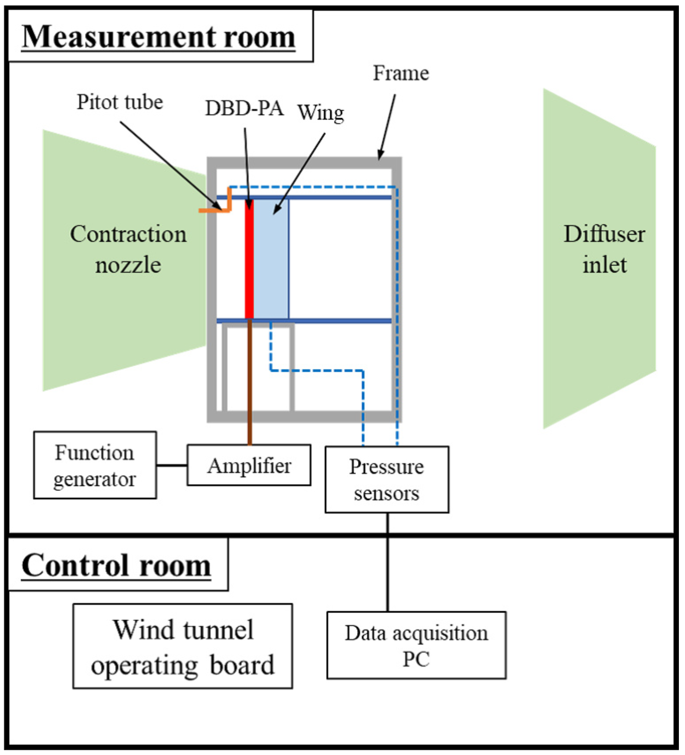
2. Experimental Setup

Experiments were conducted in a closed-type wind tunnel with a contraction nozzle of 1000 mm (width) × 850 mm (height); photos of the wind tunnel are not posted in accordance with confidentiality requirements. A test section with a width of 1020 mm, length of 970 mm, and height of 588 mm was attached to the contraction nozzle exit (Figure 3). The sidewalls of the test section were constructed with acrylic plates, and their heights were set according to the span length of the wing model, which is described later. The freestream velocity, u , was set to 20, 40, 60, and 80 m/s, corresponding to Reynolds numbers based on chord lengths of approximately 2.52 × 10 5 (252 k), 5.04 × 10 5 (504 k), 7.56 × 10 5 (756 k), and 1.008 × 10 6 (1008 k), respectively.
A two-dimensional NACA0015 airfoil with a chord length c of 200 mm and span length w of 588 mm (Figure 4) was mounted in the test section. This airfoil was manufactured using stereolithography (Tokyo Fluid Research Co., Ltd., Tokyo, Japan). There were 39 pressure ports on the model surface for time-averaged pressure measurements. The angle of attack α ranged from 6 to 22 in the present study.
The DBD-PA consisted of two sheets of 70 µm thick copper tape (3M, Cu-35C) and two sheets of 80 µm thick polyimide insulating layer (Teraoka Seisakusho, 650S, material thickness of 50 µm). The effective thickness [46,47] of the DBD-PA was approximately 0.02 mm. The widths of the exposed and insulated electrodes were 6 mm and 15 mm, respectively. These electrodes were placed at the leading edge such that the rear edge of the exposed electrode and front edge of the insulated electrode were aligned with an overlap of 1 mm. The widths of the top and bottom dielectrics were 40 mm and 30 mm, respectively. Ionic wind was generated by the actuator in the direction of the main freestream.
The exposed electrode was connected to a high-voltage amplifier (Trek, model10/40A), which amplified the originating sinusoidal waves up to a few kilovolts. The insulated electrode was connected to the ground. The sinusoidal waves were generated from a function generator (NF circuit design, WF1974). A high-voltage probe (Tectronix, P6015A) connecting the exposed and insulated electrodes was used to measure the voltage, which was monitored using an oscilloscope (Yokogawa, DLM2054). The peak-to-peak voltage V p p and base frequency f were set as 9 kVpp and 6 kHz, respectively. Preliminary particle-imaging-velocimetry experiments in a wind tunnel revealed that this output waveform can induce a velocity of approximately 2.7 m/s at a distance of 2.5 mm in the downstream direction from the DBD-PA.
The time-averaged pressure on the airfoil surface was measured using three sets of 16-channel pressure scanners (Scanivalve, ModelDSA3217). Each pressure port on the model was connected to a scanner using a Toalon tube. The pressure values were averaged over 500 samples at a sampling rate of 100 Hz. Subsequently, the pressure coefficient C p at each point was calculated using the time-averaged pressure value as described in Equation (3). Here, p and q are the local static pressure and dynamic pressure, respectively. In this experiment, the pressure scanner had a maximum error of 13.6 Pa, corresponding to Δ C p = 0.057 at the lowest freestream velocity (20 m/s).
C p = p p q = p p 0.5 ρ u 2
Figure 5 shows an overview of the wind tunnel experimental system. A wing model was installed with the frame inside the test section. The frame was attached to a contraction nozzle. Note that the distance between the contraction nozzle and diffuser inlet was sufficiently long when compared with the flowstreamwise length of the frame. The freestream velocity was controlled by the operating board in the control room. The total and static pressures of the freestream were measured using a Pitot tube installed at the exit of the contraction nozzle. The function generator and amplifier for the DBD-PA driving system and pressure sensors were set up in the measurement room. One operator stayed in the measurement room during testing to operate the DBD-PA. The tubes from the wing model and the Pitot tube were connected to the pressure sensors.
The generation of the body force by a DBD-PA and the time gradient of the input voltage are closely related [48]. Therefore, the same frequency (i.e., 6 kHz) was adapted for the base sinusoidal wave. Table 1 lists the actuation cases for each freestream velocity. The burst ratio was effectively set to 10%. Because the function generator used in this study can switch on and off only by an integer number of sinusoidal waves, when the burst frequency is high the burst ratio cannot be set to 10%, and may reach up to 50%. For example, in the case of a freestream of 20 m/s and nondimensional burst frequency of 1.0, the dimensional burst frequency was calculated to be 100 Hz. Because the base frequency was 6 kHz, the sinusoidal wave number of one burst cycle was 60. Therefore, the burst-mode actuation in this case would be 6 waves on and 54 waves off, for a corresponding burst ratio of 10%. However, in the case of a freestream of 20 m/s and nondimensional burst frequency of 30.0, the sinusoidal wave number of one burst cycle is 2. Therefore, the burst-mode actuation in this case is one wave ON and one wave OFF, and the corresponding burst ratio is 50%.

3. Results and Discussion

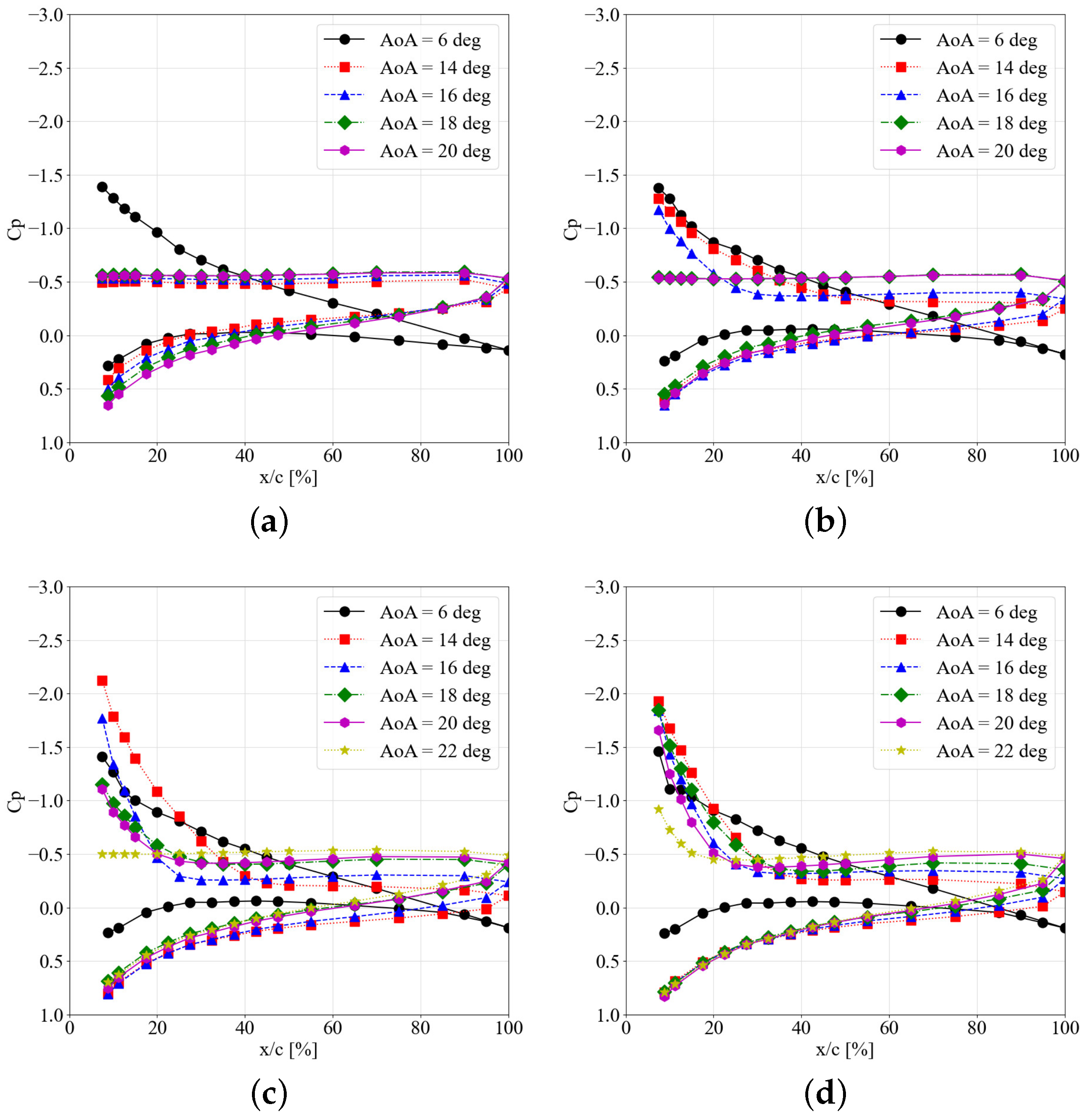
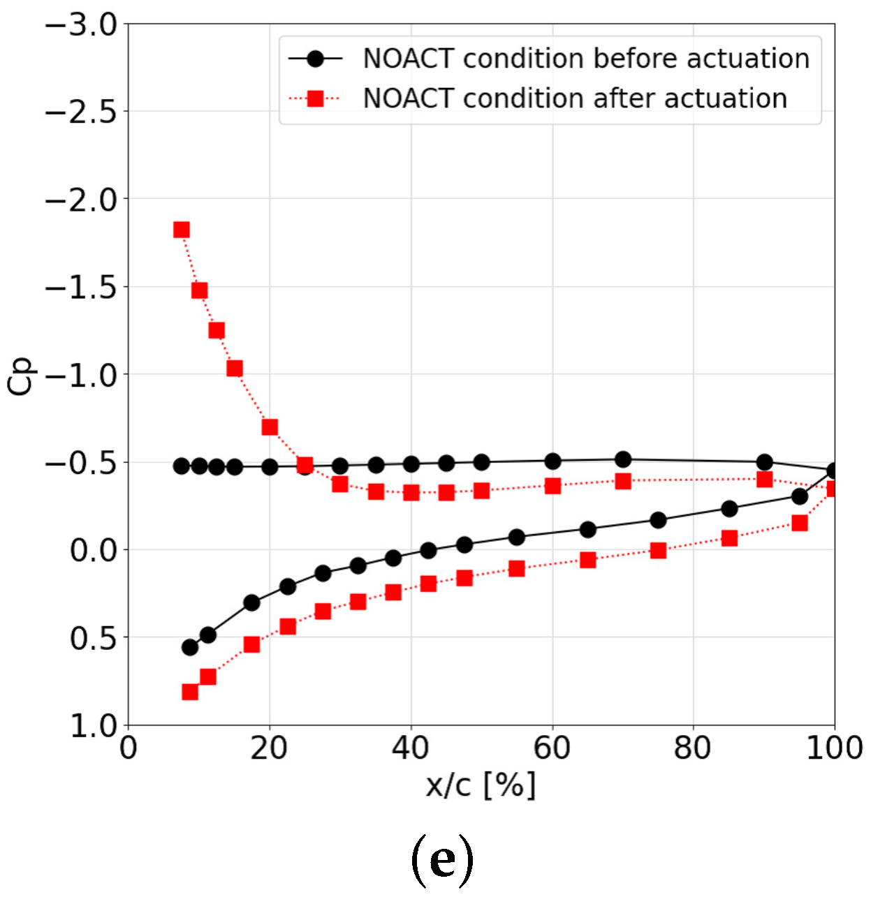
3.1. Classification of Baseflow

Figure 6 shows the C p distributions for the cases in which a DBD-PA was installed on the surface without actuation (hereinafter NOACT). Because the plasma actuator covered the leading edge ( x / c = 0%), the pressure at that point could not be acquired. Note that each C p distribution has two sets of curves. One of the curves having a negative value corresponds to the upper surface, whereas the other corresponds to the lower one. In each figure, the C p distribution at α = 6 is plotted as an example of the pre-stall angle. At this angle, the flow is attached to the suction-side surface and the C p value at the trailing edge is almost zero. For Reynolds number Re = 2.52 × 10 5 ( u = 20 m/s), all the C p distributions at α = 14 and above have a flat region over the whole suction-side surface, indicating that the flow completely separates from the leading edge (leading edge separation). In several cases with Reynolds number Re = 5.04 × 10 5 ( u = 40 m/s) and higher, a suction peak is observed near the leading edge, as in the pre-stall case. However, the C p value at the trailing edge is negative and the C p distribution near the trailing edge is flat. This indicates that the flow attaches to the surface from the leading edge to the middle of the airfoil and then separates (trailing edge separation). With increasing freestream velocity, the number of cases in which trailing-edge separation occurs increases.
Moreover, hysteresis was observed in several cases, as shown in Figure 6e. The black solid line indicates the C p distribution before actuation, and the red broken line indicates the distribution after it stops. Although the DBD-PA was stopped for both distributions, the flow fields around the airfoil were different.
In this section, three types of flow situations exist under the NOACT condition: (1) leading-edge separation, (2) trailing-edge separation, and (3) hysteresis between (1) and (2). Based on these three classifications, the relationships between flow control authority and separation condition are discussed in Section 3.2 and Section 3.3.

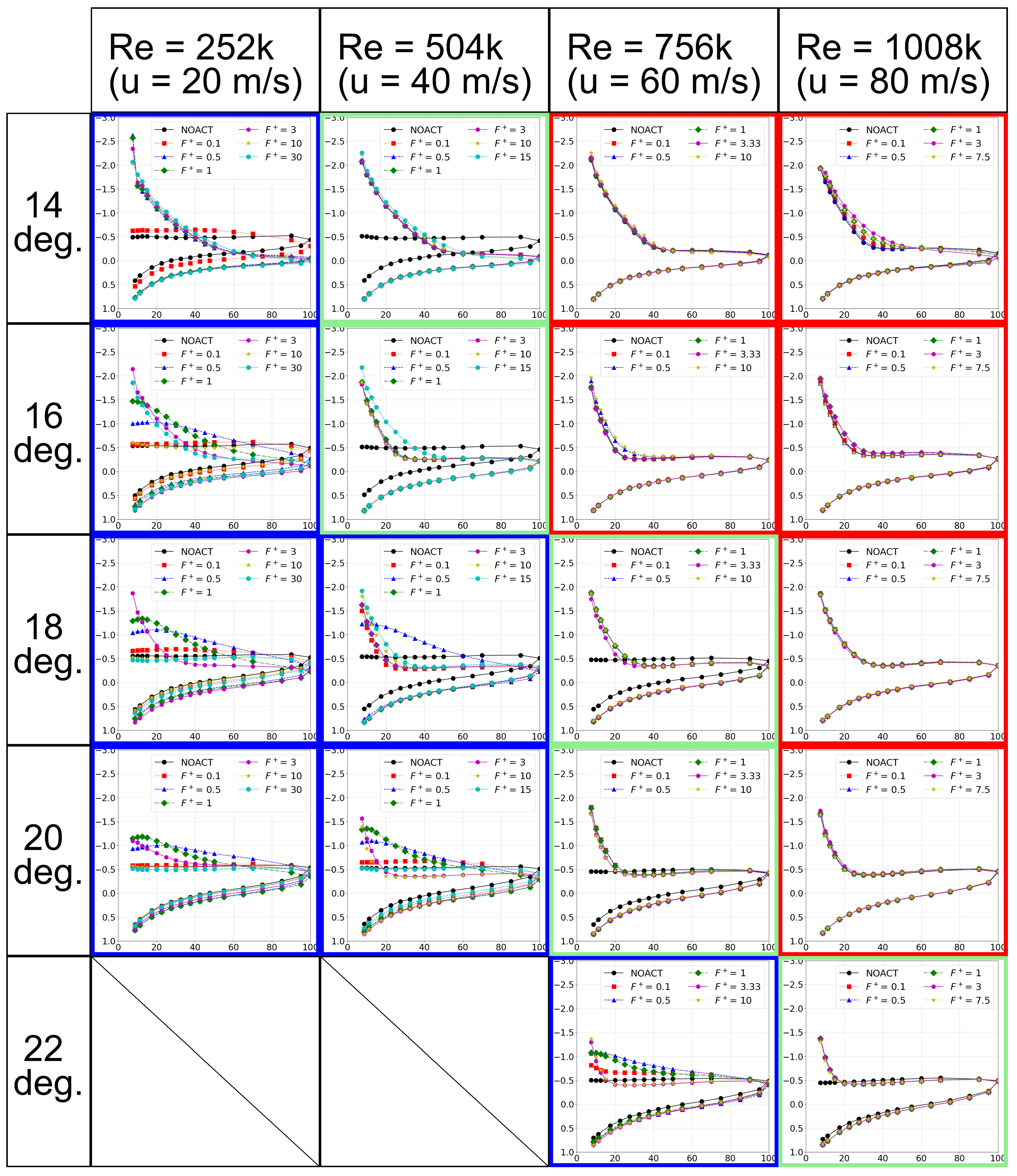
3.2. Flow Control with DBD Plasma Actuator

Figure 7 displays the C p distributions for the four freestream velocities and five angles of attack mentioned in the columns and rows, respectively. Each graph shows the C p distributions for the NOACT case (black line) and actuated cases (colored lines) according to Table 1. These plots were classified into the three categories described above based on the C p distribution in the NOACT case. The cases corresponding to the conditions of leading-edge separation, trailing-edge separation, and hysteresis are colored blue, red, and green, respectively. This figure confirms that leading-edge separation is more likely to occur under the conditions of lower freestream velocity (lower Reynolds number) and higher angle of attack than trailing-edge separation.
Under leading-edge separation conditions (cases marked with a blue frame), the C p distributions clearly change with variation in the burst frequency, except for the case with Reynolds number Re = 2.52 × 10 5 and angle of attack of α = 14 . In this case, all the actuations except for the one with a nondimensional burst frequency of F + = 0.1 were effective, leading to high suction peaks near the leading edge and near-zero C p values at the trailing edge. In other cases, a trend is obtained by actuation of a nondimensional burst frequency of approximately F + = 1 . This actuation leads to a widespread (though not high) C p distribution on the suction-side surface. This trend is obtained under this condition regardless of the freestream velocity and angle of attack. Here, the case with Re = 2.52 × 10 5 and an angle of attack α = 16 is considered. Actuation with F + = 30 is effective, whereas that with F + = 10 is not. This suggests the existence of a different trend. According to the research concerning flow fields under Re = 6.3 × 10 4 , it seems to be caused by enhancement of the turbulent transition [10,49]. Because this type of flow control is related to the natural unstable frequency at the separated shear layer [50], the optimal frequency depends on the DBD-PA installation position and freestream Reynolds number. Compared with the former type of actuation, it seems to be effective at lower angles of attack and to become less effective when the freestream velocity or angle of attack is higher. The trend of the flow field controlled by a DBD-PA with a nondimensional burst frequency of F + > 1 differs depending on the Reynolds number. For example, for a Reynolds number Re = 2.52 × 10 5 , angle of attack α =   14 , and nondimensional burst frequency F + > 1 , a suction peak occurs near the leading edge, with C p “gradually” recovering towards the trailing edge and eventually reaching almost zero. The same trend is observed for Re = 6.3 × 10 4 as well. However, in certain cases, such as with Reynolds number Re = 7.56 × 10 5 , angle of attack α = 22 , and nondimensional burst frequency F + > 3.33 , even tough a suction peak occurs near the leading edge, the Cp distribution flattens from the middle of the chord and the Cp value at the trailing edge is negative (approximately equal to that of the NOACT case here). This indicates that the flow separates from the surface in the middle, that is, trailing-edge separation occurs, although the flow is attached near the leading edge.
In comparison with leading-edge separation, the change in C p distribution from the NOACT case is smaller under trailing-edge separation conditions (the cases marked with a red frame). Although the case at Reynolds number Re = 1.008 × 10 6 and angle of attack α = 14 exhibits the largest change and variation, this change is limited to the range from the leading edge to the center of the chord. In this case, the C p at the trailing edge approaches zero as the C p distribution changes; however, the trailing-edge separation cannot be suppressed within the range used in this experiment.
Under the hysteresis condition (cases marked with a green frame), leading-edge separation occurs before actuation, and the change in C p distribution due to actuation can be clearly observed. For lower freestream velocities and angles of attack, a suction peak occurs near the leading edge and the trailing-edge C p increases to zero. As the freestream velocity and angle of attack increase, a suction peak continues to occur near the leading edge. However, the C p distribution from the center to the trailing edge hardly changes from the distribution in the NOACT case.

3.3. Discussion of Lift Coefficient

The lift coefficient C l was evaluated using the C p distribution in order to compare the experimental cases. The lift force was calculated by integrating the surface pressure while considering the local gradient. First, linear interpolation for the experimental C p distribution was conducted. Next, the local force coefficient was evaluated. Figure 8 shows the local geometry of the airfoil surface. The magnitude of the local force coefficient c f is defined using the local pressure coefficient, as provided below. Note that Δ x and θ are the chordwise length and surface gradient of the local area considered here, respectively.
c f = C p Δ x cos θ
The coordinate system x y is defined as shown in Figure 8. The local gradient θ is calculated using the symmetrical four-digit NACA airfoil formulas, as provided below. In these formulas, x is the chordwise position from 0 (leading edge) to 1.0 (trailing edge), and y u p p e r and y l o w e r are the coordinates in the y-axis direction for the upper and lower surfaces, respectively. The airfoil shape is NACA0015; therefore, the thickness t is assigned a value of 15.
θ = arctan ( d y d x )
y u p p e r ( x ) = 0.05 t ( 0.2969 x 0.1260 x 0.3516 x 2 + 0.2843 x 3 0.1015 x 4 ) y l o w e r ( x ) = 0.05 t ( 0.2969 x 0.1260 x 0.3516 x 2 + 0.2843 x 3 0.1015 x 4 )
The local force is decomposed along the axis directions. The local force on the upper surface is calculated as
c f x = c f sin θ c f y = c f cos θ
The local force on the lower surface is calculated as
c f x = c f sin θ c f y = c f cos θ
The total forces along the axes, c F x and c F y , are calculated by summing the local forces.
c F x = c f x c F y = c f y
Because the DBD-PA covers the leading edge, C p data are lacking near the leading edge, and the local force in this area is not summed. Therefore, a reference length L r e f is introduced to account for the range in which the local force was summed. The positions of the pressure holes closest to the leading edge are x / c = 0.075 (upper surface) and 0.0875 (lower surface), and the reference length is defined as L r e f = 0.91875. Finally, the lift coefficient C l is calculated using the global forces, angle of attack, and reference length, as follows:
C l = C F y cos α C F x sin α L r e f
Figure 9 shows a comparison of C l under the NOACT conditions. The large dots are the C l calculated from the data displayed in Figure 6, and the lines with dots (Refdata) are the data acquired by a balance system [51]. The dashed line displays a theoretical lift force curve slope of 2 π . Because the suction peak near the leading edge was not considered for this C l estimation, the calculated values are quantitatively different from (that is, less than) the reference results. However, the estimated C l values exhibit a trend similar to that of the reference data, especially after the stall. In the case of Re = 252 k, an abrupt Cl drop exists post-stall, similar to the case of Re = 144 K in Refdata, whereas the cl drop is more gradual in the case of a higher Reynolds number. At angles of attack of 16 or higher, the increasing trend of Cl with an increasing Reynolds number is observed. This is attributed to two reasons. First, the pressure effect has a greater influence than the viscous effect when leading-edge separation occurs; in this situation, C l calculated using the C p distribution provides a good estimation. The other is that the current pressure hole distributions can capture characteristics such as the separation point of the C p distributions when trailing-edge separation occurs. This section confirms that the qualitative characteristics can be captured using the current method of integrating the Cp values. The following section compares cases with DBD-PA.
Figure 10 displays an increase in the lift coefficient Δ C l for the actuated cases. Each value is calculated for each C l value, including that of the NOACT case with the same freestream velocity and angle of attack, such as those displayed in Figure 9. The color of each line corresponds to that of the frame in each case in Figure 7. A comparison of the trends of the lines shows that the experimental cases were classified relatively well according to the flow conditions under NOACT. In the case represented by the blue line, Δ C l reaches its maximum value at a nondimensional burst frequency of approximately F + = 0.5 , except for the case of Reynolds number Re = 2.52 × 10 5 and angle of attack α =   14 mentioned in the previous subsection. Note that the increase in CL at F = 30 for Re = 2.52 × 10 5 and α = 14 could be caused by another trend, which is discussed in the previous section. The cases represented by the green line have a larger Δ C l than those represented by the red line. This is because Δ C l is calculated using the C p distributions prior to actuation (plotted in Figure 6). If the data after actuation are applied, the Δ C l values of the cases represented by the green and red lines are similar.
The Δ C l plots of the cases represented by the blue line with a peak at F + = 0.5 appear to indicate that DBD-PA-based flow control within F + < 10 is dominated by only one mechanism. In other words, it appears that F + = 0.5 is the optimal nondimensional burst frequency in that mechanism, with the other frequencies being less effective because they deviate from the optimum. However, the C p distributions shown in Figure 7 indicate that this is not true. Multiple trends in the distribution suggest multiple control mechanisms, corresponding to the two mechanisms described in the introduction. Burst actuation with a nondimensional frequency of approximately F + = 0.5 , under which a wide negative pressure region is formed on the suction-side surface, creates a two-dimensional spanwise vortex near the leading edge [14]; on the other hand, actuation, under which a high suction peak at the leading edge is formed, enhances the turbulent transition, leading to early reattachment. Among the blue lines, several cases in which Δ C l is improved by values other than approximately F + = 0.5 are considered to be caused by this effect.
In the green and red lines, the C l peak around F + = 0.5 disappears, unlike in the blue lines. This is because these cases do not have a wide negative-pressure region on the suction-side surface. If a DBD-PA is installed near the separation point, the induced flow directly affects the separated shear layer, leading to the generation of two-dimensional spanwise vortices and a wide negative-pressure region. Considering the Reynolds number, the separation type is turbulent rather than laminar. However, as the surface pressure is almost constant in the separated region, the separation point can be roughly estimated as the starting point of the flat region in the C p distribution. For example, according to this estimation, the separation point is roughly estimated as x / c = 0.4 in the case corresponding to Reynolds number Re = 7.56 × 10 5 and angle of attack α = 14 . Therefore, the separation point is predicted to be far from the leading edge, and a wide negative pressure region is not generated in the green and red cases. Despite the above discussion, the predicted separation point shifts toward the trailing edge and C l increases accordingly in several cases. Because the effective frequencies differ depending on the flow conditions, unlike in the cases represented by the blue line, it is difficult to draw a general conclusion as to an appropriate burst frequency. The flow is considered turbulent at the separation point, as mentioned above. Thus, the movement of the separation point would be caused by another mechanism, rather than by the turbulent transition.
In addition, unlike in the cases represented by the blue line, the effect of a DBD-PA is smaller at an angle of attack α = 14 than at α = 16 with a freestream velocity of u = 60 m/s. This is due to the distance between the DBD-PA and the separation point. Because the separation point at α = 14 is located further downstream than that at α = 16 , the effect of the DBD-PA at the leading edge becomes small at the separation point. Therefore, actuation closer to the separation point may improve the flow control authority. However, the actual flow conditions, such as the velocity and angle of attack, change; additionally, the separation point may change. It is difficult for a spanwise DBD-PA at a fixed position, such as the one used in this study, to respond to such changes in the separation point. Sato applied a vortex generator-type plasma actuator (VG-PA) to control the turbulent separation that occurs under a Reynolds number Re = 1.6 × 10 6 [52]. In the VG-PA, two actuators are installed facing each other along the chordwise direction and generate streamwise vortices, similar to a passive vortex generator. The results show that streamwise vortices were generated by operating the VG-PA, leading to the generation of small-scale turbulent vortices. Sato concluded that these turbulent vortices promote negative Reynolds stress in the boundary shear layer, resulting in a delay in the turbulent separation. Based on this conclusion, the burst drive of the spanwise DBD-PA attached to the leading edge can be considered to change the turbulent state near the separation point. Because the VG-PA is installed in the streamwise direction, it may be robust against movement of the separation point. However, such an arrangement does not generate a two-dimensional spanwise vortex. A combination of a spanwise DBD-PA near the leading edge and a VG-PA may have control authority for a wide range of flow conditions from trailing-edge separation to leading-edge separation.
Experiments conducted over a wide range of Reynolds numbers and angles of attack show that the control trends clearly depend on the difference in the separation conditions (leading-edge separation or trailing-edge separation). These results indicate that the position and burst frequency of DBD-PAs should be selected based on the separation conditions. Regarding leading-edge separation, burst actuation with a nondimensional frequency of F + = 0.5–1.0 is considered a general strategy for a wide range of Reynolds numbers. However, an effective control mechanism for trailing-edge separation has not yet been established. In addition, because the position of trailing-edge separation is more likely to change depending on the flow conditions than that of leading-edge separation, it is difficult to select the appropriate position of a spanwise DBD-PA. To establish an appropriate control strategy, it is important to distinguish between the separation conditions.
In practical environments, changes in the external wind occur, and other environmental concerns such as rain may affect DBD-PAs. Lilley et al. [53] have reported that when a DBD-PA is wet, the induced thrust decreases and the thrust distribution becomes non-uniformly three-dimensional. Therefore, the flow control authority of DBD-PA in practical environments may differ from that evaluated in wind tunnel experiments. Tanaka et al. installed DBD-PAs on a 300-kW wind turbine and conducted experiments intermittently for one year in an external environment [54]. To prevent abnormal discharge due to rain, they installed a protection system on the DBD-PA power supply [55]. In addition, they discussed the flow control authority of DBD-PAs. It is essential to consider the external described concerns above in order to construct DBD-PA systems that can be used in practical environments.

4. Conclusions

In this study, a separation-control investigation was conducted using a DBD-PA on an NACA0015 airfoil over a wide range of Reynolds numbers (2.52 × 10 5 to 1.008 × 10 6 ), angles of attack (post-stall conditions), and nondimensional burst frequencies. The control authority was evaluated using time-averaged C p distributions and the calculated C l values.
The flow fields under the NOACT condition, in which a DBD-PA was installed on the surface without actuation, were evaluated using the C p distributions. Based on these results, we classified the flow fields under the NOACT condition into three types: (1) leading-edge separation, (2) trailing-edge separation, and (3) hysteresis between (1) and (2). The DBD-PA actuation was applied in each case, and the results were compared. In the leading-edge separation cases, actuation with a burst frequency of approximately F + = 0.5 creates a wide negative pressure region on the suction-side surface, whereas several cases with higher burst frequency produce a suction peak near the leading edge. In the trailing-edge cases, several actuations cause a change in the C p distribution, which indicates shifting of the turbulent separation position. The lift coefficient C l was evaluated using the C p distributions. The plots depicting increases in the lift coefficient show a clear peak at approximately F + = 0.5 in the leading-edge-separation case. In the trailing-edge separation cases, several actuations increase the lift coefficient according to shifting of the turbulent separation position.
As mentioned in the introduction, previous studies have generally focused on only one of these parameters, and have discussed flow control mechanisms. In this study, the flow control authority was investigated over a wide range of Reynolds numbers greater than 2.52 × 10 5 , angles of attack, and burst frequencies, and the relationships between the flow control authority and separation condition was discussed. Our results show that the control trends clearly depend on the difference in the separation conditions, i.e., leading-edge separation or trailing-edge separation. Thus, in order to establish an appropriate control strategy, it is important to distinguish between the separation conditions.

Author Contributions

Conceptualization, K.F. and T.N.; methodology, S.S. (Satoshi Sekimoto), K.F., M.A., T.N. and T.M.; software, S.S. (Satoshi Sekimoto); validation, M.A., Y.M., S.S. (Satoshi Shimomura) and T.N.; investigation, S.S. (Satoshi Sekimoto); resources, M.A., S.I., H.N., T.N. and K.F.; data curation, S.S. (Satoshi Sekimoto), Y.M. and S.S. (Satoshi Shimomura); writing—original draft preparation, S.S. (Satoshi Sekimoto), K.F., H.N. and T.N.; writing—review and editing, S.S. (Satoshi Sekimoto) and K.F.; visualization, S.S. (Satoshi Sekimoto); supervision, K.F., M.A., S.I., H.N., T.N. and T.M.; project administration, T.N. and K.F.; funding acquisition, K.F. All authors have read and agreed to the published version of the manuscript.

Funding

This research was funded by the Japanese Society for the Promotion of Science (JSPS) through Grants-in-Aid for Scientific Research (KAKENHI) grant numbers JP15H02324 and JP18H03816.

Institutional Review Board Statement

Not applicable.

Informed Consent Statement

Not applicable.

Data Availability Statement

Not applicable.

Conflicts of Interest

The authors declare no conflict of interest.

References

  1. Corke, T.C.; Post, M.L. Overview of Plasma Flow Control: Concepts, Optimization, and Applications. In Proceedings of the 43rd AIAA Aerospace Sciences Meeting and Exhibit, Reno, NV, USA, 10–13 January 2005. [Google Scholar]
  2. Goksel, B.; Greenblatt, D.; Rechenberg, I.; Nayeri, C.N.; Paschereit, C.O. Steady and Unsteady Plasma Wall Jets for Separation and Circulation Control. In Proceedings of the 3rd AIAA Flow Control Conference, San Francisco, CA, USA, 5–8 June 2006. [Google Scholar]
  3. Greenblatt, D.; Goksel, B.; Schule, C.Y.; Romann, D.; Paschereit, C.O. Dielectric Barrier Discharge Flow Control at Very Low Flight Reynolds Numbers. AIAA J. 2008, 46, 1528–1541. [Google Scholar] [CrossRef]
  4. Asada, K.; Ninomiya, Y.; Oyama, A.; Fujii, K. Airfoil Flow Experiment on the Duty Cycle of DBD Plasma Actuator. In Proceedings of the 47th AIAA Aerospace Sciences Meeting including the New Horizons Forum and Aerospace Exposition, Orlando, FL, USA, 5–8 January 2009. [Google Scholar]
  5. Bénard, N.; Moreau, E.; Griffin, J.; Cattafesta, L.N., III. Plasma flow control—Autonomous lift improvement by slope-seeking. In Proceedings of the 39th AIAA Fluid Dynamics Conference, San Antonio, TX, USA, 22–25 June 2009. [Google Scholar]
  6. Boeuf, J.P.; Lagmich, Y.; Unfer, T.; Callegari, T.; Pitchford, L. Electrohydrodynamic force in dielectric barrier discharge plasma actuators. J. Phys. D 2007, 40, 652–662. [Google Scholar] [CrossRef]
  7. Font, G.I.; Enloe, C.L.; McLaughlin, T.E. Plasma Volumetric Effects on the Force Production of a Plasma Actuator. AIAA J. 2010, 48, 1869–1874. [Google Scholar] [CrossRef]
  8. Nishida, H.; Abe, T. Validation Study of Numerical Simulation of Discharge Plasma on DBD Plasma Actuator. In Proceedings of the 42nd AIAA Plasmadynamics and Lasers Conference, Honolulu, HI, USA, 27–30 June 2011. [Google Scholar]
  9. Benard, N.; Moreau, E. Electrical and mechanical characteristics of surface AC dielectric barrier discharge plasma actuators applied to airflow control. Exp. Fluids 2014, 55, 1–43. [Google Scholar] [CrossRef] [Green Version]
  10. Sekimoto, S.; Nonomura, T.; Fujii, K. Frequency Effects in Burst-mode Actuation of Dielectric-Barrier-Discharge Plasma Actuator for Separation Control. AIAA J. 2017, 55, 1385–1392. [Google Scholar] [CrossRef]
  11. Sidorenko, A.A.; Zanin, B.Y.; Postnikov, B.V.; Budovsky, A.D.; Starikovskii, A.Y.; Roupassov, D.V.; Zavialov, I.N.; Malmuth, N.D.; Smereczniak, P.; Silkey, J.S. Pulsed Discharge Actuators for Rectangular Wings Separation Control. In Proceedings of the 45th AIAA Aerospace Sciences Meeting and Exhibit, Reno, NV, USA, 8–11 January 2007. [Google Scholar]
  12. Sato, M.; Okada, K.; Nonomnura, T.; Aono, H.; Yakeno, A.; Asada, K.; Abe, Y.; Fujii, K. Massive Parametric Study by LES on Separated-fow Control around Airfoil using DBD Plasma Actuator at Reynolds Number 63,000. In Proceedings of the 43rd Fluid Dynamics Conference, San Diego, CA, USA, 24–27 June 2013. [Google Scholar]
  13. Visbal, M.R. Strategies for control of transitional and turbulent flows using plasma-based actuators. Int. J. Comput. Fluid Dyn. 2010, 24, 237–258. [Google Scholar] [CrossRef]
  14. Fujii, K. Three flow features behind the flow control authority of DBD plasma actuator: Result of high-fidelity simulations and the related experiments. Appl. Sci. 2018, 8, 546. [Google Scholar] [CrossRef] [Green Version]
  15. Sato, M.; Okada, K.; Asada, K.; Aono, H.; Nonomura, T.; Fujii, K. Unified mechanisms for separation control around airfoil using plasma actuator with burst actuation over Reynolds number range of 103–106. Phys. Fluids 2020, 32, 025102. [Google Scholar]
  16. Matsunuma, T. Effects of Burst Ratio and Frequency on the Passage Vortex Reduction of a Linear Turbine Cascade Using a Dielectric Barrier Discharge Plasma Actuator. Actuators 2022, 11, 210. [Google Scholar] [CrossRef]
  17. Shimomura, S.; Sekimoto, S.; Oyama, A.; Fujii, K.; Nishida, H. Closed-loop flow separation control using the deep q network over airfoil. AIAA J. 2020, 58, 4260–4270. [Google Scholar] [CrossRef]
  18. Ogawa, T.; Asada, K.; Sekimoto, S.; Tatsukawa, T.; Fujii, K. Dynamic burst actuation to enhance the flow control authority of plasma actuators. Aerospace 2021, 8, 396. [Google Scholar] [CrossRef]
  19. Mabe, J.H.; Calkins, F.T.; Wesley, B.; Woszidlo, R.; Taubert, L.; Wygnanski, I. Single Dielectric Barrier Discharge Plasma Actuators for Improved Airfoil Performance. J. Aircr. 2009, 46, 847–855. [Google Scholar] [CrossRef]
  20. Corke, T.C.; Enloe, C.L.; Wilkinson, S.P. Dielectric Barrier Discharge Plasma Actuators for Flow Control. Annu. Rev. Fluid Mech. 2010, 42, 505–529. [Google Scholar] [CrossRef]
  21. Matsuno, T.; Kawaguchi, M.; Fujita, N.; Yamada, G.; Kawazoe, H. Jet Vectoring and Enhancement of Flow Control Performance of Trielectrode Plasma Actuator Utilizing Sliding Discharge. In Proceedings of the 6th AIAA Flow Control Conference, New Orleans, LA, USA, 25–28 June 2012. [Google Scholar]
  22. Hatamoto, A.; Nakai, K.; Nishida, H. Experimental Study on the Working Characteristics of Tri-Electrode Plasma Actuator Utilizing a Combination of Corona and Barrier Discharges. Actuators 2022, 11, 322. [Google Scholar] [CrossRef]
  23. McGowan, R.; Corke, T.C.; Matlis, E.; Kaszeta, R.; Gold, C. Pulsed-DC Plasma Actuator Characteristics and Application in Compressor Stall Control. In Proceedings of the 54th AIAA Aerospace Sciences Meeting, San Diego, CA, USA, 4–8 January 2016. [Google Scholar]
  24. Sato, S.; Mitsuhashi, K.; Enokido, T.; Komuro, A.; Ando, A.; Ohnishi, N. Surface-charge control strategy for enhanced electrohydrodynamic force in dielectric barrier discharge plasma actuators. J. Phys. Appl. Phys. 2021, 54, 455203. [Google Scholar] [CrossRef]
  25. Roupassov, D.V.; Nikipelov, A.A.; Nudnova, M.M.; Starikovskii, A.Y. Flow Separation Control by Plasma Actuator with Nanosecond Pulsed-Periodic discharge. AIAA J. 2009, 47, 168–185. [Google Scholar] [CrossRef]
  26. Takashima, K.; Zuzeek, Y.; Lempert, W.R.; Adamovich, I.V. Characterization of a surface dielectric barrier discharge plasma sustained by repetitive nanosecond pulses. Plasma Sources Sci. Technol. 2011, 20, 055009. [Google Scholar] [CrossRef]
  27. Komuro, A.; Takashima, K.; Konno, K.; Tanaka, N.; Nonomura, T.; Kaneko, T.; Ando, A.; Asai, K. Schlieren visualization of flow-field modification over an airfoil by near-surface gas-density perturbations generated by a nanosecond-pulse-driven plasma actuator. J. Phys. D Appl. Phys. 2017, 50, 215202. [Google Scholar] [CrossRef]
  28. Komuro, A.; Takashima, K.; Suzuki, K.; Kanno, S.; Nonomura, T.; Kaneko, T.; Ando, A.; Asai, K. Gas-heating phenomenon in a nanosecond pulse discharge in atmospheric-pressure air and its application for high-speed flow control. Plasma Sources Sci. Technol. 2018, 27, 104005. [Google Scholar] [CrossRef]
  29. Komuro, A.; Ogura, N.; Ito, M.; Nonomura, T.; Asai, K.; Ando, A. Visualization of density variations produced by alternating-current dielectric-barrier-discharge plasma actuators using the background-oriented schlieren method. Plasma Sources Sci. Technol. 2019, 28, 055002. [Google Scholar] [CrossRef]
  30. Little, J.; Takashima, K.; Nishihara, M.; Adamovich, I.; Samimy, M. Separation Control with Nanosecond-Pulse-Driven Dielectric Barrier Discharge Plasma Actuators. AIAA J. 2012, 50, 350–365. [Google Scholar] [CrossRef]
  31. Kato, K.; Breitsamter, C.; Obi, S. Flow separation control over a Go 387 airfoil by nanosecond pulse-periodic discharge. Exp. Fluids 2014, 55, 1795. [Google Scholar] [CrossRef]
  32. Kelley, C.L.; Bowles, P.O.; Cooney, J.; He, C.; Corke, T.C.; Osborne, B.A.; Silkey, J.S.; Zehnle, J. Leading-edge separation control using alternating-current and nanosecond-pulse plasma actuators. AIAA J. 2014, 52, 1871–1884. [Google Scholar] [CrossRef]
  33. Moreau, E.; Debien, A.; Benard, N.; Zouzou, N. Nanosecond-pulsed dielectric barrier discharge plasma actuator for airflow control along an NACA0015 airfoil at high reynolds number. IEEE Trans. Plasma Sci. 2016, 44, 2803–2811. [Google Scholar] [CrossRef]
  34. Zheng, J.; Cui, Y.; Zhao, Z.; Li, J.; Khoo, B. Investigation of airfoil leading edge separation control with nanosecond plasma actuator. Phys. Rev. Fluids 2016, 1, 073501. [Google Scholar] [CrossRef]
  35. Komuro, A.; Takashima, K.; Tanaka, N.; Konno, K.; Nonomura, T.; Kaneko, T.; Ando, A.; Asai, K. Multiple control modes of nanosecond-pulse-driven plasma-actuator evaluated by forces, static pressure, and PIV measurements. Exp. Fluids 2018, 59, 129. [Google Scholar] [CrossRef]
  36. Komuro, A.; Kanno, S.; Suzuki, K.; Ando, A.; Nonomura, T.; Asai, K. Flow-Control Characteristics with Nanosecond-Pulse Plasma Actuator for Different Airfoil Shapes. AIAA J. 2021, 59, 5301–5309. [Google Scholar] [CrossRef]
  37. Grossman, K.; Bohdan, C.; VanWie, D. Sparkjet actuators for flow control. In Proceedings of the 41st Aerospace Sciences Meeting and Exhibit, Reno, NV, USA, 6–9 January 2003; p. 57. [Google Scholar]
  38. Caruana, D.; Rogier, F.; Dufour, G.; Gleyzes, C. The plasma synthetic jet actuator, physics, modeling and flow control application on separation. Aerospace Lab 2013, 6, 1–13. [Google Scholar]
  39. Zong, H.; van Pelt, T.; Kotsonis, M. Airfoil flow separation control with plasma synthetic jets at moderate Reynolds number. Exp. Fluids 2018, 59, 169. [Google Scholar] [CrossRef] [Green Version]
  40. Thomas, F.O.; Corke, T.C.; Iqbal, M.; Kozlov, A.; Schatzman, D. Optimazation of Dielectric Barrier Discharge Plasma Actuator for Active Aerodyanamic Flow Control. AIAA J. 2009, 47, 2169–2178. [Google Scholar] [CrossRef] [Green Version]
  41. Sato, S.; Furukawa, H.; Komuro, A.; Takahashi, M.; Ohnishi, N. Successively accelerated ionic wind with integrated dielectric-barrier-discharge plasma actuator for low-voltage operation. Sci. Rep. 2019, 9, 5813. [Google Scholar] [CrossRef] [PubMed] [Green Version]
  42. Moreau, E.; Debien, A.; Breux, J.M.; Benard, N. Control of a turbulent flow separated at mid-chord along an airfoil with DBD plasma actuators. J. Electrost. 2016, 83, 78–87. [Google Scholar] [CrossRef]
  43. Zhang, X.; Huang, Y.; Wang, X.; Wang, W.; Tang, K.; Li, H. Turbulent boundary layer separation control using plasma actuator at Reynolds number 2000000. Chin. J. Aeronaut. 2016, 29, 1237–1246. [Google Scholar] [CrossRef] [Green Version]
  44. Ebrahimi, A.; Hajipour, M. Flow separation control over an airfoil using dual excitation of DBD plasma actuators. Aerosp. Sci. Technol. 2018, 79, 658–668. [Google Scholar] [CrossRef]
  45. Sato, M.; Asada, K.; Nonomura, T.; Aono, H.; Yakeno, A.; Fujii, K. Mechanisms for turbulent separation control using plasma actuator at Reynolds number of 1.6 × 10⁶. Phys. Fluids 2019, 31, 095107. [Google Scholar]
  46. Wilkinson, S.P.; Siochi, E.; Sauti, G.; Xu, T.B.; Meador, M.; Guo, H. Evaluation of dielectric-barrier-discharge actuator substrate materials. In Proceedings of the 45th AIAA Plasmadynamics and Lasers Conference, Atlanta, GA, USA, 16–20 June 2014; p. 2810. [Google Scholar]
  47. Portugal, S.; Roy, S.; Lin, J. Functional relationship between material property, applied frequency and ozone generation for surface dielectric barrier discharges in atmospheric air. Sci. Rep. 2017, 7, 6388. [Google Scholar] [CrossRef]
  48. Nakano, A.; Nishida, H. The effect of the voltage waveform on performance of dielectric barrier discharge plasma actuator. J. Appl. Phys. 2019, 126, 173303. [Google Scholar] [CrossRef]
  49. Sato, M.; Aono, H.; Yakeno, A.; Nonomura, T.; Fujii, K.; Okada, K.; Asada, K. Multifactorial Effects of Operating Conditions of Dielectric-Barrier-Discharge Plasma Actuator on Laminar-Separated-Flow Control. AIAA J. 2015, 53, 2544–2559. [Google Scholar] [CrossRef]
  50. Sato, M.; Nonomura, T.; Okada, K.; Asada, K.; Aono, H.; Yakeno, A.; Abe, Y.; Fujii, K. Mechanisms for laminar separated-flow control using dielectric-barrier-discharge plasma actuator at low Reynolds number. Phys. Fluids 2015, 27, 117101. [Google Scholar] [CrossRef]
  51. Sheldahl, R.E.; Klimas, P.C. Aerodynamic Characteristics of Seven Symmetrical Airfoil Sections through 180-Degree Angle of Attack for Use in Aerodynamic Analysis of Vertical Axis Wind Turbines; Technical Report; Sandia National Laboratories: Albuquerque, NM, USA, 1981. [Google Scholar]
  52. Sato, M. Mechanisms for Turbulent-Separation-Control at Reynolds Number of 1.6 × 10⁶ using Vortex-Generator-Type Plasma Actuators-Comparison with Spanwise-Type Plasma Actuators. In Proceedings of the AIAA AVIATION 2022 Forum, Chicago, IL, USA, 27 June–1 July 2022; p. 3849. [Google Scholar]
  53. Lilley, A.J.; Roy, S.; Michels, L.; Roy, S. Performance recovery of plasma actuators in wet conditions. J. Phys. D Appl. Phys. 2022, 55, 155201. [Google Scholar] [CrossRef]
  54. Tanaka, M.; Kubo, N.; Kawabata, H. Plasma actuation for leading edge separation control on 300-kW rotor blades with chord length around 1 m at a Reynolds number around 1.6×10⁶. J. Phys. Conf. Ser. 2020, 1618, 052013. [Google Scholar] [CrossRef]
  55. Tanaka, M.; Kubo, N.; Kawabata, H.; Suzuki, K.; Bhandari, S.; Watanabe, N.; Sato, H.; Takeyama, M.; Minegishi, K.; Oryu, Y. The First Trial Operation of Plasma Assisted 300 kW Wind Turbinewith Durable, Retrofitted DBD Electrodes. In Proceedings of the Wind Energy Science Conference (WESC) 2019, Cork, Ireland, 17–20 June 2019. [Google Scholar]
Figure 1. Schematic of a DBD-PA.
Actuators 12 00043 g001
Figure 2. Schematic of burst-mode driving. In this figure, the burst ratio ( B R ) is set to 12.5%.
Actuators 12 00043 g002
Figure 3. Dimensions of the test section.
Actuators 12 00043 g003
Figure 4. NACA0015 stereolithography wing model.
Actuators 12 00043 g004
Figure 5. Overview of wind tunnel experimental system. Note that the devices for DBD-PA input voltage measurement are omitted.
Actuators 12 00043 g005
Figure 6. C p distributions of the NOACT cases: (a) Re = 2.52 × 10 5 ( u = 20 m/s); (b) Re = 5.04 × 10 5 ( u = 40 m/s); (c) Re = 7.56 × 10 5 ( u = 60 m/s); (d) Re = 1.008 × 10 6 ( u = 80 m/s); (e) Example of hysteresis situation ( α = 18 , u = 60 m/s): Note that each C p distribution has two sets of curves; one of the curves, with a negative value, corresponds to the upper surface, whereas the other corresponds to the lower one.
Actuators 12 00043 g006aActuators 12 00043 g006b
Figure 7. Difference in C p distributions according to the burst frequency under each flow condition.
Actuators 12 00043 g007
Figure 8. Local pressure force evaluation.
Actuators 12 00043 g008
Figure 9. Comparison of C l under NOACT conditions. Large dots denote C l calculated using data displayed in Figure 6, and lines with dots are reference data (Refdata) acquired by a balance system [51]. The dashed line displays a theoretical lift force curve slope of 2 π .
Actuators 12 00043 g009
Figure 10. Increase in the lift coefficient Δ C l due to the DBD-PA. The values are calculated for each C l value, including that of the NOACT case, with the same freestream velocity and angle of attack displayed in Figure 9. The color of each line corresponds to that of the frame for each case displayed in Figure 7: (a) Re = 2.52 × 10 5 ( u = 20 m/s); (b) Re = 5.04 × 10 5 ( u = 40 m/s); (c) Re = 7.56 × 10 5 ( u = 60 m/s); (d) Re = 1.008 × 10 6 ( u = 80 m/s).
Actuators 12 00043 g010
Table 1. Experimental cases for each freestream velocity. The nondimensional burst frequency and corresponding burst ratio are shown for each case.
Re = 252 kRe = 504 kRe = 756 kRe = 1008 k
( u = 20 m/s)(v u = 40 m/s)( u = 60 m/s)( u = 80 m/s)
0.1 (10.0%)0.1 (10.0%)0.1 (10.0%)0.1 (10.0%)
0.5 (10.0%)0.5 (10.0%)0.5 (10.0%)0.5 (10.0%)
1.0 (10.0%)1.0 (10.0%)1.0 (10.0%)1.0 (13.3%)
3.0 (10.0%)3.0 (10.0%)3.3 (16.7%)3.0 (20.0%)
10.0 (16.7%)10.0 (33.3%)10.0 (50.0%)7.5 (50.0%)
30.0 (50.0%)15.0 (50.0%)
Disclaimer/Publisher’s Note: The statements, opinions and data contained in all publications are solely those of the individual author(s) and contributor(s) and not of MDPI and/or the editor(s). MDPI and/or the editor(s) disclaim responsibility for any injury to people or property resulting from any ideas, methods, instructions or products referred to in the content.

