1. Introduction
In recent years, with the rapid development of the artificial intelligence technology, computer vision and natural language processing algorithms in robot filed, the applications of robot in complex environmental field have been realized [
1,
2,
3,
4,
5]. As a branch of robot researching, bionic robot shows more flexible motion characteristics in engineering applications [
6,
7,
8,
9,
10,
11]. Inspired by the biological snake, the snake robot not only has strong flexibility and malleability in practical applications, but also can achieve stable movement on rugged terrain in pipes and narrow gaps. Due to these excellent performances of snake robot, it has a great significance in complex scene maintenance, search and rescue [
12,
13,
14,
15,
16].
As a bionic robot, the gait planning of snake robot is the simulation of the movement of biological snake. The researches on snake robot are mainly carried out three aspects: model design, ontology implementation and motion control [
17]. In order to adapt to the efficient and flexible operation in multiple environments, the shape of snake robot is usually designed as a multi joint series, coupled and highly redundant structure. In 1972, Prof. Hirose, from Tokyo Institute of technology, Japan, based on the modular design concept, the authors established the motion model of the snake robot with serpentine movement and conducted the prototype ACM-
, but it can only achieve two-dimensional motion [
18,
19]. Through further researching and upgrading prototype, the research teams designed a snake robot with three-dimensional motion ability and amphibious. Wang et al. [
20] proposed a multi degree of freedom snake robot with alternating single axis pitch joint and yaw joint, and realized multi-functional three-dimensional motion by using the method of backbone curve. Each module of the GMD snake robot developed by the German National Information Technology Research Center. This type of snake robot consists a yaw joint and a pitch joint, which makes the body more flexible [
21]. The research teams of Carnegie Mellon University, United States, adopted the steering gear, reducer, connecting rod and driving rod in the structural designing, established the snake robot with orthogonal joints, named as Uncle Sam, which can realize the climbing movement of complex outer pipes [
22]. Pepter et al. designed a cable driven mobile serpentine robot composed of modular coupling linkage mechanism to reduce the size of the snake robot and improve the motion efficiency [
23].
The controllability and stability analysis of snake robot motion control is the key and difficult problem for researchers. It is mainly divided into two aspect, one is to study the motion characteristics of the snake robot by establishing the kinematic model and the dynamic model, and the other is to study the motion of the specific gait of the robot through the control function method. The mainstream control methods are the serpenoid curve fitting control function method [
18], the continuous backbone curves model control method [
24] and the CPG (central neurogenesis controller) control method [
25]. Among them, due to the advantages of simplicity and efficiency, the method of control function has widely used in engineering [
26]. In the motion control of snake robot, the control algorithm of adapting to different terrain contours and avoiding obstacles is an important research topic in the motion control of snake robot. At present, some researchers also use the relevant knowledge of artificial neural network to study the robot control and the automatic development of morphology [
27,
28,
29,
30,
31].
The above methods are applied to control different snake robot gaits, including serpentine gait, traveling wave gait, rolling gait and climbing gait. In these gaits, the snake robot’s body has the characteristics of frequent periodic swing, and the switching between straight-line and turning motion are easy to cause the snake robot body oscillation and side slip. Ehsan et al. [
32] designed a path tracking control rate based on guidance, and proposed an exponentially stable joint control scheme for robot shape dynamics to realize the trajectory tracking of the robot within a small error boundary. Zhao et al. [
33] proposed a multi gait continuous flexible snake robot based on flexible spring rotation, torsion and release, and studied a variety of gait. Tatsuya [
34] proposed a method to realize gait switching in complex environment by linking curvature and torsion curves. In reference [
35], an extended Kalman filter (EKF) to snake robot head trajectory tracking method without lateral constraint plane is proposed. Belala [
36] proposed a mobile operation method to realize the movement of spiral rolling gait on the outer pipe surface by using the whole body motion of the snake robot.
In the process of snake robot gait transition, the change of control parameters will cause the side slip and shake of the moving gait. In order to solve the above problems, this paper studies the head stable gait of the snake robot, and proposes an adaptive transition gait planning method to solve the jitter and side slip problems effectively. The main contributions of this paper are as follows: a polynomial interpolation function method is proposed to solve the jitter problem in gait switching. Meanwhile, in order to further find the optimal interpolation time, an optimal interpolation method based on dichotomy is proposed.
The reminder of this paper is organized as follows. A simple structure description of the snake robot and the CoppeliaSim simulation platform are given in
Section 2.
Section 3 introduces the relevant gaits and the model analyzing of snake robot.
Section 3.4 shows the main results in snake robot trajectory planning.
Section 5 gives some simulations to verity the correctness of the obtained results. Finally, the conclusion and future researches are proposed in Section
15.
2. Structure and Simulation Platform Description
In the natural environment, the biological snake has a complex multi joints structure, which generates the driving force through the friction between the muscles of each joint and the ground. The snake robot mostly used to imitate the biological snake is a multi-module series structure, which controls the snake robot to show a snake like gait through the driving relationship between the joints, to adapt to walking in different environment. The main difference of modular snake robot design lies in the connection mode between modules. The simplest design is to use a single yaw direction rotating pair connection perpendicular to the ground. This simplest connection mode can realize the snake robot’s serpentine motion, however, this connection designing makes the snake robot only move in two-dimensional space and lacks the adaptability to complex environment. In this paper, the orthogonal connection method is used to show the relationship of each modules in snake robot connection mode. Orthogonal connection means that the adjacent connection joints, the rotating pairs are vertically distributed in the yaw direction and the pitch direction, as shown in
Figure 1. The rectangular coordinate system is established with the base
A and the rod
B as the origin, and the end coordinates of rod
C is expressed as:
here
l denotes the length from the rod
B to rod
C,
denotes the yaw joint rotation angle, and
is the pitch joint rotation angle.
From
Figure 1, we can know that the working space at the end of connecting rod
C is an empty tubular space with outer diameter of
and inner diameter of 0. Due to the simple structure, easy driving and strong stability, the orthogonal connection is widely used in robot modeled.
The CoppeliaSim simulation platform can provide a wealth of physical simulation engines, as well as a variety of development environments, such as script, interface and communication. It is convenience for data collection and result verification of robot simulation experiments. In this paper, the model building of snake robot is shown as follows:
Firstly, a snake robot model based on orthogonal connection is built in SolidWorks software, it is composed of the head, middle and end of the snake, respectively, and the forms the snake robot is assembled by connection. The model of the snake robot is shown in
Figure 2.
Next, saving the assembled model in SolidWork software as
file and importing it into CoppeliaSim software to form the appearance model of snake robot, as shown in
Figure 3a. The snake robot in this paper is composed of 13 modules, which are connected by 12 orthogonal joints.
Finally, the robot model tree is built according to the dependency between the modules of the snake robot, and the simulation entity structure design of the snake robot is completed, as shown in
Figure 3b.
Remark 1. In the construction of simulation model, the file is imported into the CoppeliaSim software, which does not equip with solid simulation characteristics. So we need to simplify the structure after the geometric feature extraction, and add corresponding physical simulation characteristics, such as joint connection, mass, friction, etc.
In this paper, the interface function is written in the dynamic library. The CoppeleaSim simulation platform transfer the dynamic library in running script to realize the communication with . The communication node is “”. The node subscribes to the control parameter information and executes the callback function to realize the interaction of subscription information. At the same time, the sensor information is published on the node.
The motion control system framework of the snake robot is shown in
Figure 4. First, start the “
” node, set the control parameters information in the interactive terminal, publish the control parameters as the topic information of “
”, subscribe to the control parameters information of the “
” node in the snake robot control script of the CoppeliaSim software, and execute the callback function to update the running parameters of the snake robot in the simulation environment. At the same time, the sensor information of the simulation environment is published as “
”, “
” and “
” topic information through the “
” node. The sensors information are subscribed and processed under
, the relevant information is written to the local file. Meanwhile, the CoppeliaSim simulation platform and
system are designed in the form of asynchronous and parallel, to avoid the interruption of simulation due to data acquisition and program control and ensure the continuity of snake robot operation in the simulation environment. In this paper, the parameterized sinusoidal control function method is used to study the gait of the snake robot, and the operation is realized by controlling the joint angle of each module of the snake robot. To facilitate study of the running posture of the snake robot, the number of modules of the snake robot is 13, with 12 orthogonal joints.
3. The Analysis of Motion Gait
3.1. Serpentine Gait
Serpentine gait is the fastest and most efficient motion mode of snake robot. Based on the orthogonal joint, it can realize snake-like serpentine motion with the driven wheel, and the gait control function can be expressed as:
here
is the rotation angle of the
i-th joint,
k represents the motion control gain,
denotes joint angle offset,
is the angular frequency,
A is the amplitude.
Based on the orthogonal joint design of the snake robot, the odd number joints keep the angle at zero, and drive the even number joints to rotate to the specified angle to realize the serpentine gait. We analyze the control function of the snake robot by changing a single variable as follows:
- (1)
Fixed the parameters
, choosing
respectively, the attitude of snake robot is shown in
Figure 5.
- (2)
Fixed the parameters
, choosing
, respectively, the attitude of snake robot is shown in
Figure 6.
- (3)
Fixed the parameters
, choosing
, respectively, the attitude of snake robot is shown in
Figure 7.
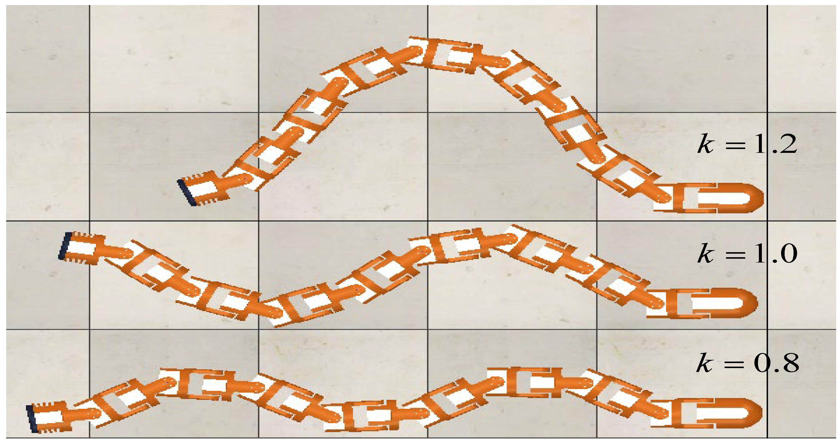
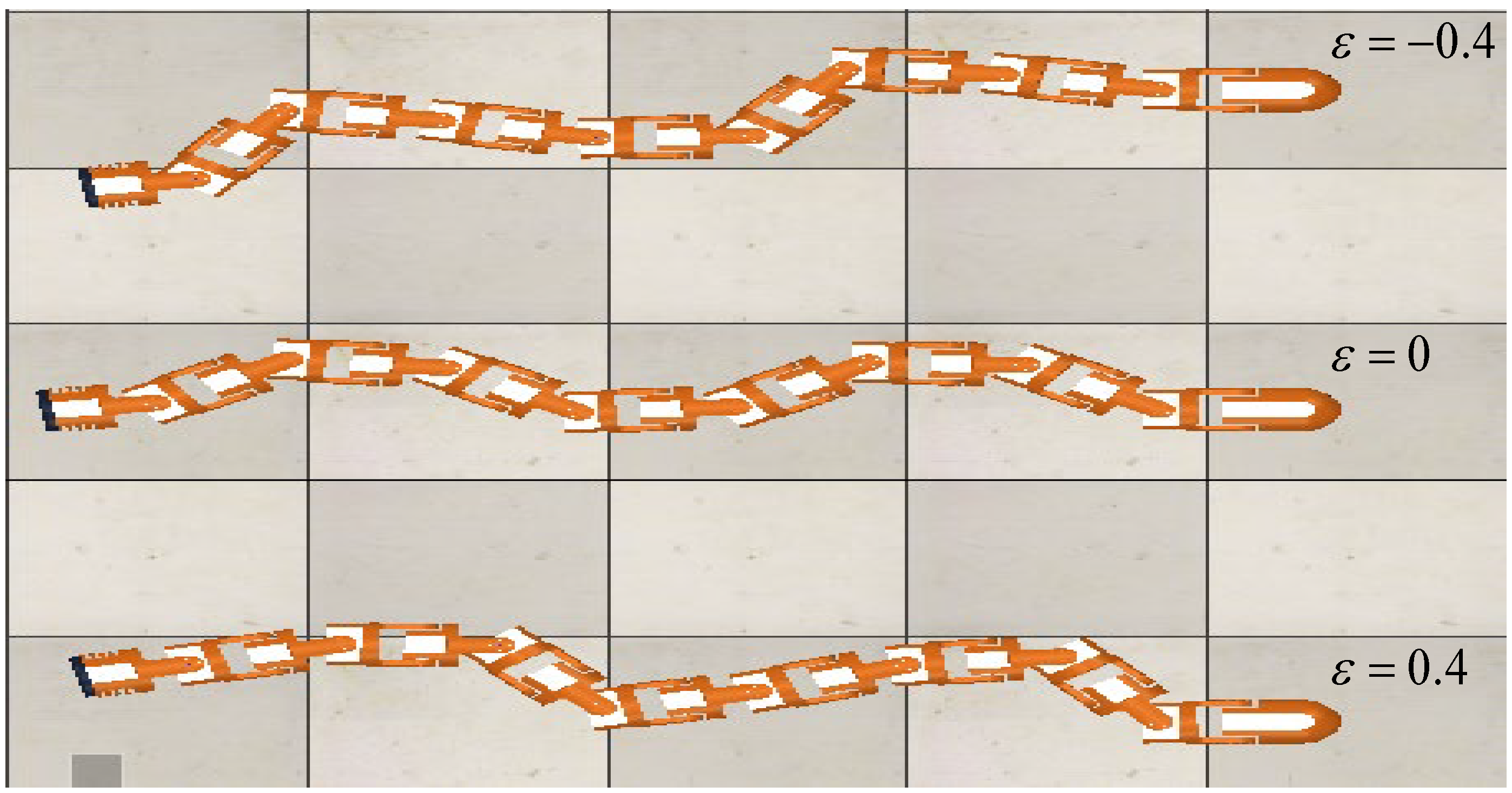
The effects of the relevant control parameters on the serpentine gait are summarised as follows:
If increasing A, the amplitude of the serpentine curve of snake robot becomes higher, the number of wave crests remains as the same.
The larger k is, the greater the serpentine amplitude is, and the number of wave crests decreases.
The parameter affects the deviation of snake robot waveform, when the parameter is positive and larger, the angle of the head waveform to the right of the forward direction is larger, when it is negative and the smaller, the greater the angle of the head waveform to the left of the forward direction is.
The parameter depends on the performance of the motor and generally set as constant.
Based on the above parameter analysis of the serpentine gait, it is found that the parameter affecting the swing amplitude of the snake robot’s head is
A, and the effect of stabilizing the snake’s head can be achieved by controlling the swing amplitude of the joints. The sigmoid function is used to suppress the serpentine gait control function. The expression is:
here
v is the adjust parameter of sigmoid function rising rate,
is the
ith rotation angle,
n is the expection joints,
k is the motion control parament,
denotes the joint angle offset. The sigmoid function can suppress the swing amplitude of the joints close to the head, and the greater the suppression if the closer joints to the head. The control of snake robot based on the suppression makes the angle between the head joint and the forward direction of the body swing around zero, then, it can reduce the swing of the head joints. From the above researches on the snake robot’s head stable serpentine gait, the control method based on sigmoid function suppression can effectively slow down the shaking of the head and improve the forward efficiency of the snake robot.
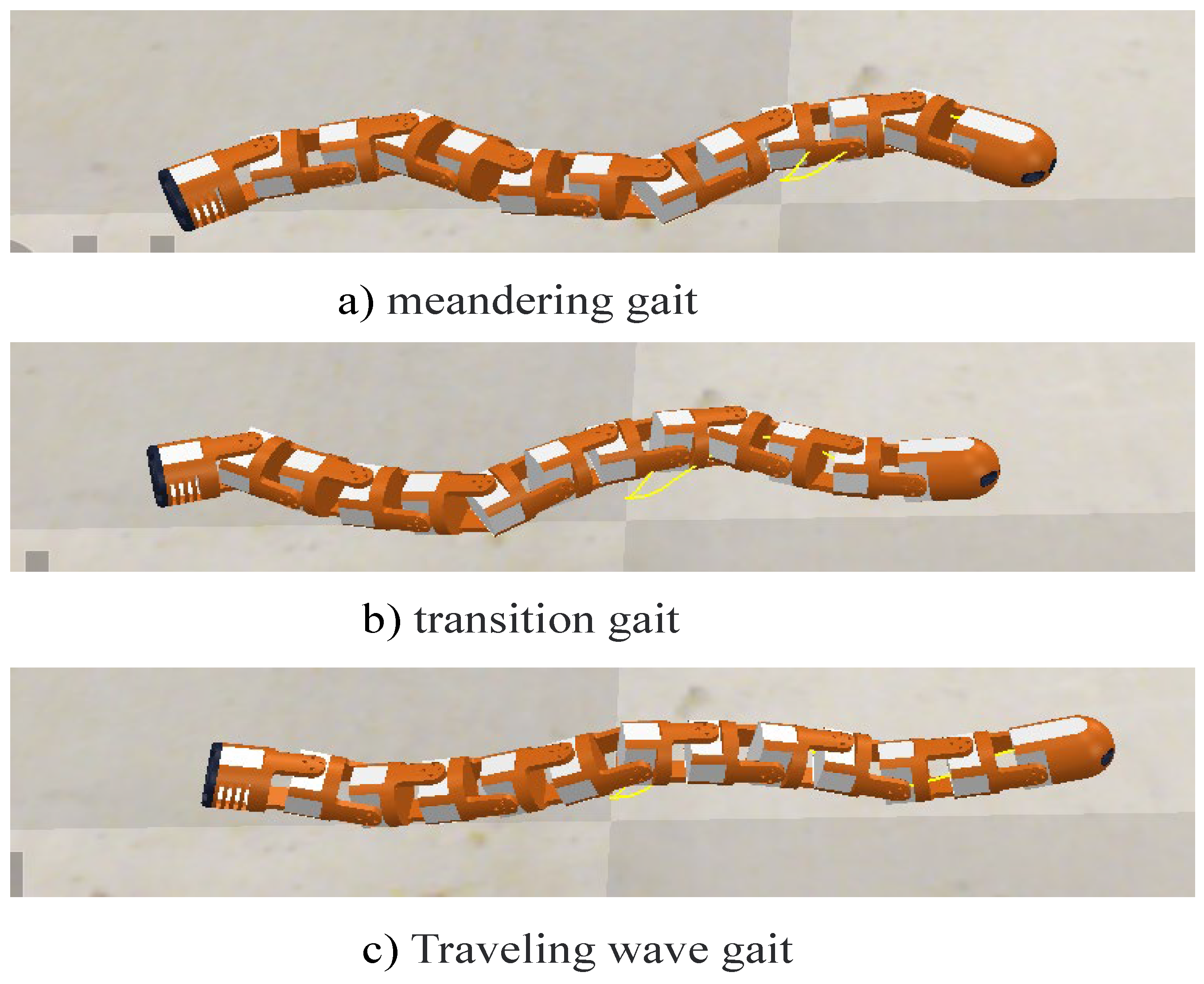
3.2. Traveling Wave Gait
The traveling wave gait is inspired by the creeping movement of snake in the biological world. By rhythmically lifting part of the body, snake can walk through a narrow space. Based on the serpentine gait of the control function method, it can be deduced that the joint angle of the traveling wave gait of the orthogonal snake robot is expressed as
here
is used to change the waveform offset angle and generally set to zero. Traveling wave gait is the realization of serpentine movement in a plane perpendicular to the ground. Although the running efficiency of traveling wave gait is lower than that the serpentine gait with driven wheels, it can realize the operation of snake robot in narrow space and realize the climbing of inner pipe by squeezing the inner wall of pipe.
3.3. Dynamic Analysis of Serpentine Gait
The serpentine gait of the bionic snake robot is the matching of the snake’s crawling curve. When analyzing the mechanical model of the snake robot’s serpentine gait, the driving torque at the joint of
i in the snake robot is
, the length of the connecting rod is
, we have
The stress of the snake robot’s serpentine gait joint is shown in
Figure 8:
When
approaches zero, we decompose the driving force of the snake robot, and the tangential direction of
the forward direction is decomposed into
, and the normal direction is
, the rotation angle of adjacent driving joints is
, then:
Let
, due to
tend to zero, we have
. Inserting (
5) into (
6), we have
According to the above formula, the tangential force of the joint driving force is proportional to the derivative of the time, while the normal torque and the driving torque are equal. If the length of the snake robot is
l, the driving force of the snake robot can be expressed as:
The sum of normal forces is
There are two conditions for the snake robot to realize forward motion. One is the forward thrust generated by the joint greater than the friction in the forward direction, the other is to overcome the upward sliding. Let the tangential friction is
, the normal friction is
, and the conditions for the snake robot to move forward are
The maximum normal static friction between the body and the ground is
, then, the conditions for no sideslip under the serpentine gait is
The friction in the forward direction of the machine body is sliding friction, which is slightly less than the maximum static friction,
here
is the tangential sliding friction coefficient,
G is the weight of the body. Then, the forward condition of snake robot without side sliding is shown as:
3.4. Adaptive Transition Gait
Trajectory planning is the main content of motion control in the field of the robot. The trajectory planning is based on motion interpolation to achieve the movement of the body, including trajectory planning and path planning. In trajectory planning, not only ensure the continuity of displacement and velocity, but also the continuity of acceleration is required to ensure the smoothness of trajectory.
The gait of snake robot is generated by the trajectory planning of the motion joints, and the gait planning can be realized by controlling the angle of the joint module. The output angle, angular velocity and angular acceleration of the snake robot’s serpentine gait joint based on the control function method can be expressed as
where
refers to the parameter of controlling the turning of the snake robot. The angle change of a single joint of the snake robot during turning is shown in
Figure 9.
Due to the instantaneous angle jump of the snake robot in the movement process will lead to a sharp increase in the acceleration of the joint, the driving force of the joint is greater than the maximum normal static friction of the snake robot, resulting in the side slip and the vibration of the body. In the field of robot control, the smoothness and continuity of motion control determine the stability of robot. In order to overcome the above challenges, this paper proposes a method based on polynomial interpolation, which can reach the desired smoothly and avoid jitter.
In the polynomial interpolation method, the first-order interpolation method adopted the linear increasing method to take the interpolation points. The disadvantage of this method is that the tracking is the connecting line of a series of key points, so it cannot realize the smoothing of the curve. On the other hand, due to the sharp change of speed, the step changes, which causes a great burden on the control of the motor. The second-order interpolation method uses the quadratic curve to connect the key points. Although this method can get a smooth trajectory, the speed is continuous, and it also has the characteristics of constant acceleration and deceleration. When the acceleration and deceleration are switched, the symbols are instantaneous opposite, and there is also a step phenomenon, which is not conducive to the control of the system. Meanwhile, it does great damage to the motor. The trajectory and speed of cubic polynomial interpolation method are continuous, the acceleration is not necessarily continuous. Discontinuous acceleration will impact the body and make the body jitter. In view of the above situation, this paper proposes an interpolation method based on quintic polynomial, which can not only realize the continuity and smoothness of trajectory and velocity, but also realize the continuity of acceleration. In the previous sections, the dynamic analysis of the snake robot’s meandering motion is carried out, and the driving force stability has a key impact on the gait of the snake robot. Therefore, in this section, the quintic polynomial interpolation method is applied to the transitional gait planning of the snake robot.
4. Main Results
In previous sections, the dynamics of the snake robot is analyzed, and the driving force stability has a key impact on the gait of the snake robot. Therefore, in this section, the quintic polynomial interpolation method is applied to the transition gaits planning of the snake robot.
Theorem 1. In analyzing the motion planning of snake robot’s serpentine gait, through the quintic polynomial interpolation method, if the parameters meet the following constraints, it can obtain the unique solution of the snake robot’s dynamic equation.
Proof. In the motion control of snake robot, the five polynomial equations of angle, angular velocity and angular acceleration can be expressed as
here, the initial anger is
, the angular velocity denotes
, the angular acceleration is
, and the terminal anger is
, the angular velocity denotes
, the angular acceleration is
, which satisfy the following constraints
According to the above six constraint conditions, the unique solution of the quintic polynomial difference function can be obtained. □
Theorem 2. In the gait switching process of snake robot, by using the quintic polynomial interpolation method, the snake robot can realize adaptive transition gait switching.
Proof. In motion gait of snake robot, all the turning gaits can be represented by its control function. For simplicity, here we taking a single joint as the research object, the snake robot switches from gait to the target gait at the time point
, the optimal interpolation time is set as
. The output of the single joint angle interpolation gait angle, angular velocity and angular acceleration when the snake robot switches from gait 1 to gait 2 is shown as
Figure 10,
The starting angle of the interpolated gait is
, the angular velocity is
, the angular acceleration is
, the angle of the terminal gait is
, the angular velocity is
, the angular acceleration is
. Then, the parameters of interpolation quintic polynomial are satisfying
We can find the quintic polynomial interpolation function
related to interpolation duration
and interpolation start point
, the angular acceleration
. The torque of the joint can be expressed as
here
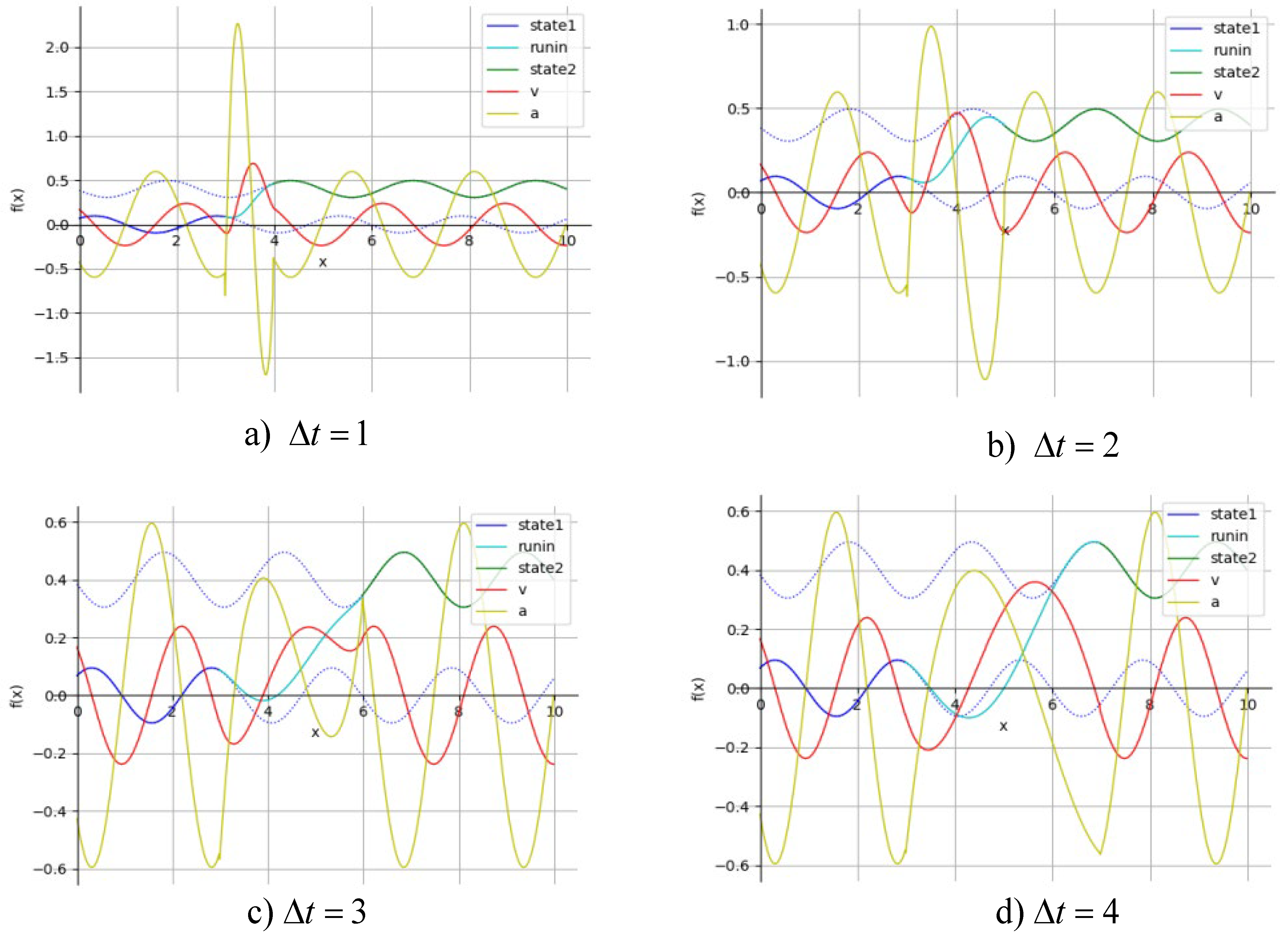
J is the torque of inertia, that is, the inertia of the rigid body rotating around the axis. According to the dynamic analysis of the snake robot serpentine gait, the condition that the snake robot does not slip is that the component of the driving force in the normal direction is less than the maximum lateral static friction, and the normal force is the quadratic product of the torque. Assuming that the maximum output acceleration of each joint angle of the transition gait is
, the transition gait planning of the snake robot without side slip can be simplified to search for the most appropriate interpolation time
. We can obtain that the longer interpolation period can acquire the smoother curve, and the maximum angular acceleration of the interpolation section is smaller. However, after a certain time, the maximum acceleration of the interpolation function no longer reduces. The longer interpolation time affects the efficiency of gait switching of the snake robot, as shown in
Figure 11. Therefore, it is of great significance to find the optimal interpolation time for adaptive planning of snake robot’s transitional gait. □
In this paper, we design an optimal interpolation time search based on dichotomy, and the minimum search step is 0.5 s, the maximum output angular acceleration threshold of the joint is
, the dichotomy algorithm is shown as Algorithm 1:
| Algorithm 1 Dichotomy Search |
- 1:
Input ; - 2:
ifthen - 3:
; - 4:
if then - 5:
; - 6:
if then - 7:
; - 8:
if then - 9:
; - 10:
else - 11:
- 12:
end if - 13:
end if - 14:
end if - 15:
end if
|
Based on the algorithm, we know the time complexity of the algorithm is , the optimal search interval can be set according to experience, and the acceleration expression is a cubic equation, which can solve the interval maximum value of the interpolation function. The time delay exists in the calculation process. The calculation time is , multiplied by the binary search algorithm step , it can obtain the calculation time , and the snake robot realizes the transitional gait planning at the time .
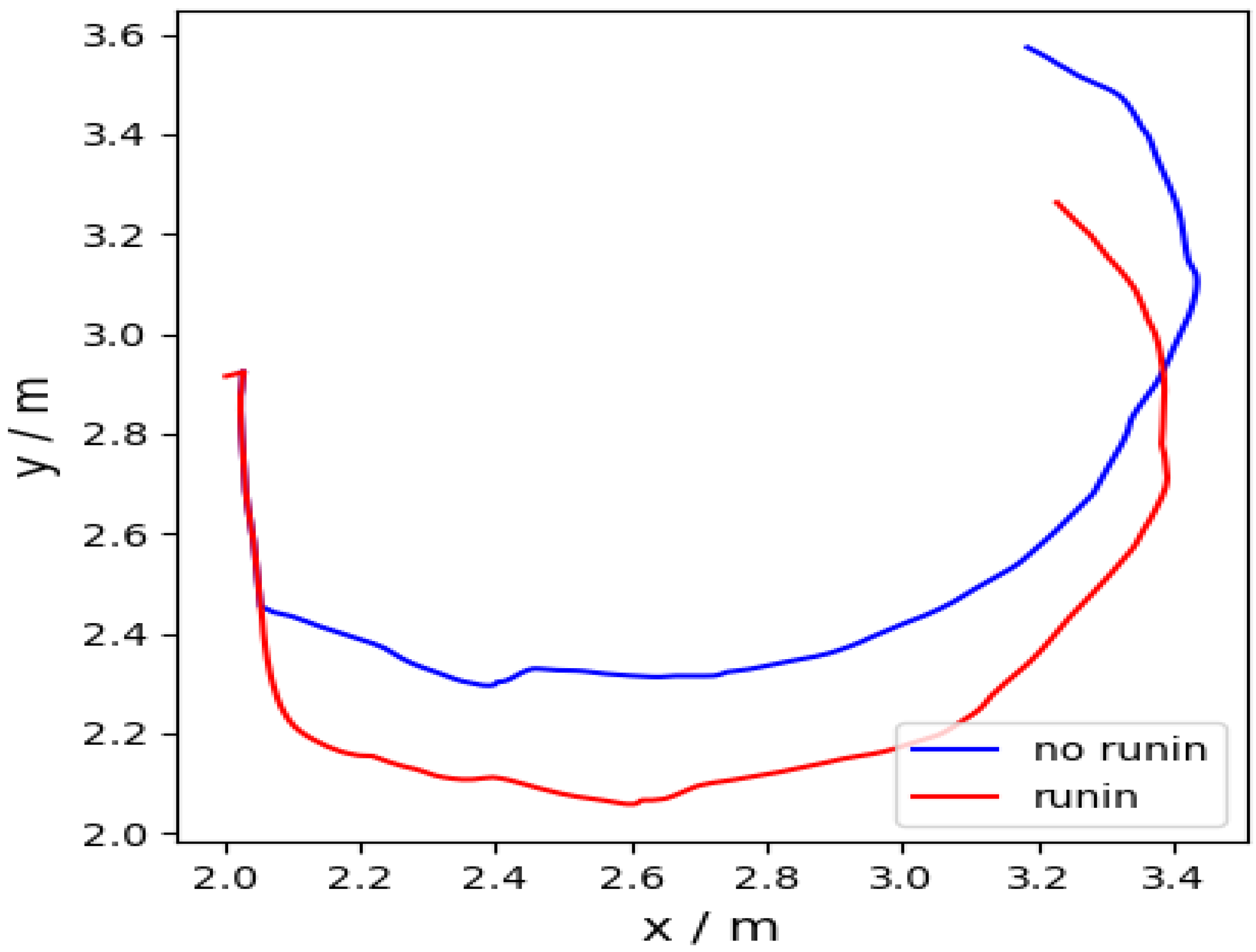
Remark 2. Based on the above analysis, the adaptive transition gait planning of the snake robot can be realized at any time between all gaits under the control function method. The head stable gait based on sigmoid function is suppressed the output of the first two joints, so the self-adaptive transition gait of the serpentine gait is suitable for the head stable serpentine gait. The control of the snake robot’s smooth turning will change the angular velocity to realize the smooth operation from straight line to different turning gait, which is conducive to the stability of the head joint camera and makes the running track smoother.


