Article

Design and Analysis of a High Power Density Permanent Magnet Linear Generator for Direct-Drive Wave Power Generation

1
School of Energy and Power, Jiangsu University of Science and Technology, Zhenjiang 212100, China
2
Power Plant Division, Shanghai Marine Diesel Engine Research Institute, Shanghai 201108, China
*
Author to whom correspondence should be addressed.
Actuators 2022, 11(11), 327; https://doi.org/10.3390/act11110327
Submission received: 24 September 2022 / Revised: 5 November 2022 / Accepted: 7 November 2022 / Published: 10 November 2022
(This article belongs to the Special Issue Linear Motors and Direct-Drive Technology)

Abstract

:
Wave energy is a new type of clean energy. Aiming at a low wave energy density and small wave height in China’s coastal areas, a tubular permanent magnet linear generator (PMLG) with a short stroke, small volume, and high power density is designed for wave power generation. Firstly, the generator’s electromagnetic parameters are analyzed by the analytical method, and the magnetic circuit topology and basic structure of the generator are analyzed by the equivalent magnetic circuit method (EMCM). Then, the finite element method (FEM) is used to analyze the influence law of the generator’s basic structural parameters on the output electromotive force (EMF) and its sinusoidal characteristics. The multi-factor and multi-level analysis is carried out based on the orthogonal test method to study the size parameters of the above analysis, and the optimal structure parameter combination for the generator is obtained. Finally, the prototype is trial-produced and tested for steady-state and transient performance to confirm the accuracy of the simulation calculations, and the output performance under no-load and load conditions is examined. The results show that both the optimized prototype’s power density and the output EMF’s sinusoidal properties have been improved under the proposed scheme.

1. Introduction

With the worsening of world’s energy crisis, wind, solar [1,2], wave [3], and other new energy sources have become research priorities in recent years. The wave energy is a kind of energy formed by the wind blowing across the sea surface [4]. The marine areas in different geographical locations have different wave characteristics [5]. The novel direct-drive wave power system with a simple structure and an improved efficiency adopts a linear generator [6,7] as the energy converter, which can directly match the up and down reciprocating motion of the wave [8,9]. Among the existing studies, the main linear generators applied to wave power generation are hybrid magnetic field modulated linear generators (HMFMLG) [10], switched reluctance linear generators (SRLG) [11,12], and permanent magnet synchronous linear generators (PMSLG) [13,14], etc.
Although HMFMLG has a superior output performance and a higher use efficiency of permanent magnets (PM), its complicated construction is a big disadvantage that is hard to overcome. The SRLG’s structure is simple and inexpensive to produce, but it produces a lot of noise and has poor stability. The PMSLG [15,16,17] has the benefits of high power, a compact structure, and high efficiency. Liu et al. [18] proposed a two-body direct-drive wave energy converter, in which the translator and stator of the PMLG were mounted on two buoys to extract energy from the relative motion between two oscillating buoys. Zhang et al. [19] and Jang, S.M. et al. [20] studied a PMLG of the Halbach PM array to improve the air gap magnetic field of the generator, in which the effects of different slot and pole pitches on the detent force were analyzed, but the waveform of the EMF was not analyzed. Zhou et al. [21] proposed a calculation model based on the EMCM and used it to analyze the magnetic circuits corresponding to the stator core, PM, and air gap, respectively. Finally, the partial magnetic circuits were combined to obtain a complete equivalent magnetic circuit model for this motor. Arslan et al. [22] analyzed the correlation between the variable structure parameters of the motor and the efficiency and volume based on the effect surface optimization method and multi-objective genetic algorithm. Finally, the comprehensive performance of the motor was improved, and the optimal value of the motor was obtained.
This paper designed a high power density PMLG based on the Halbach array, which is suitable for operation in the near coastal environment of China. The PMLG is designed preliminarily by the analytical method and its electromagnetic parameters are determined. In order to increase power density, improve power production efficiency, and decrease the THD of the EMF, the variation law of induction EMF’s peak and the THD under various parameters from the perspectives of yoke thickness, tooth width, and PM thickness was examined in depth by the FEM. The multi-parameter optimization is carried out based on the orthogonal design method to obtain the optimal parameter combination. Finally, the steady-state and dynamic performance of the protype are tested. The results show that the optimized PMLG has the advantages of high power density, high generation efficiency, and a small THD of the EMF.

2. Analytical Calculation of PMLG

Aiming at a low wave energy density and small wave height in China, this study develops a small Halbach array PMLG that uses the fundamental structure of a long secondary and short primary. As a wave generator, the primary is relatively fixed, and the secondary is directly connected to the wave collecting apparatus. The secondary is driven by the wave to perform reciprocating linear motion to produce electricity. Based on the wave characteristics, the generator performance requirements are shown in Table 1. According to the generator design index, the electromagnetic properties of the generator are calculated and analyzed using the analytical method.

2.1. Electromagnetic Calculation of PMLG

The main dimensions of the rotary motor are the armature diameter and the axial effective length. The linear motor evolves from the rotary motor and its corresponding main dimensions are the primary effective length and the inner diameter.
The primary effective length l e f is denoted as:
l e f = 2 P τ
Speed:
V = 2 τ f N
According to the characteristics of small wave power in summer, taking V = 0.5 m/s, the polar distance τ = 25 mm can be calculated. In this paper, the PMLG based on the Halbach PM array [23,24,25,26] adopts the structure of three slots and four poles, so the primary effective length of the generator can be obtained. Generally, the calculated power is determined by the rated index of the generator:
P = m E I
Phase electromotive force:
E = 4.44   f N K d p Φ δ K Φ
E = ( 1 + Δ U ) U N
Rated power:
P N = m U N I cos φ
Air gap magnetic flux:
Φ δ = B δ α i π D s _ i n τ
Electric load:
A = 2 m N I 2 P τ
Tidy up bring in:
2 P τ D s _ i n = P 13.94 α i K d p K Φ A B δ V
where, P’ is the calculated power, E is the phase EMF, I is the phase current, N is the number of winding turns, Kdp is the fundamental winding coefficient, K Φ is the air gap flux waveform coefficient, B δ is the air gap magnetic density, α i is the calculated pole arc coefficient, P is the pole logarithm, Δ U is the voltage regulation, D s _ i n is the stator’s inner diameter and φ is the power factor.
It is clear that the generator’s primary dimensions are dependent on the calculated power, electromagnetic load, and air gap magnetic density.

2.2. Stator Design

According to the above formula, the stator’s effective length can be calculated. To determine the turns per coil turns, the generator’s EMF and fundamental winding coefficient are used as guides, and their relationship is as follows:
N = E 4.44 f Φ δ K d p K Φ
According to the diameter of the coil, the area occupied by the coil can be calculated, and the size of the teeth and grooves can be further determined.
The crack ratio KS is defined as the ratio of the stator inner diameter Ds_in to outer diameter Ds_out, and the size of the primary outer diameter is determined by the crack ratio. Current research indicates that when KS = 0.45, the output power and power density of the generator are the maximum. The preliminary design parameters of the PMLG can be derived using the aforementioned analytical procedure, and its structure is shown in Figure 1.

3. Analysis of Equivalent Magnetic Circuit Model

The distribution of the magnetic field inside the motor is determined by converting the calculation of the motor magnetic field into the calculation of the magnetic circuit using the EMCM. The magnetic circuit corresponding to the model is shown in Figure 2. The air gap allows the magnetic force lines produced by the radially magnetized PM to penetrate the stator teeth and yoke before moving on to the adjacent PM. Finally, the axial magnetized PM returns to the initial PM to form a closed loop. The magnetic circuit includes the magnetomotive force source F c , the PM reluctance R m , the air-gap reluctance R g , the stator tooth reluctance R c , the stator yoke reluctance R o , and the translator yoke reluctance R i .
Where, the magnetomotive force is generated by the PM:
F C = H C l = B r l μ 0 μ r
H C   is the PM’s coercivity, l is the length of the PM along the magnetization direction, B r   is the PM’s remanence, μ 0 is the vacuum permeability, and μ r is the relative permeability of the PM.
The Carter coefficient k δ is introduced, and its computation follows. It takes into account how stator slotting affects the effective air gap length:
k δ = ( w s + w t ) ( 5 g + w t ) ( w s + w t ) ( 5 g + w t ) w t 2
The air gap reluctance R g is obtained from the reluctance equation as:
R g = r 2 r k δ d r 2 π r μ 0 w s = k δ ( ln r ln r 2 ) 2 π μ 0 w s
The magnetoresistance of PM is:
R m r = r 1 r 2 d r 2 π r μ 0 μ r τ r = ln r 2 ln r 1 2 π μ 0 μ r τ r
R m a = τ a μ 0 μ r π ( r 2 2 r 1 2 )
The internal resistance of the yoke and stator teeth is negligible in comparison to the air-gap resistance. According to the magnetic circuit theorem, the PM’s magnetic flux in the air gap can be expressed as follows:
Φ = F C 2 R g + R m r + R m a = H C ( r 2 r 1 ) + H C τ a k δ ( ln r ln r 2 ) π μ 0 w s + ln r 2 ln r 1 2 π μ 0 μ r τ r + τ a π μ 0 μ r ( r 2 2 r 1 2 )
B δ = Φ 2 π r τ r = H C ( r 2 r 1 ) + H C τ a 2 r τ r k δ ( ln r 3 ln r 2 ) μ 0 w s + r ( ln r 2 ln r 1 ) μ 0 μ r + 2 r τ r τ a μ 0 μ r ( r 2 2 r 1 2 )
where w s is the tooth width, w t is the notch width, g is the air gap length, r is the radius of air gap, r 1 is the inside radius of the PM, r 2 is the outside radius of the PM, r 3 is the inside radius of the stator teeth, τ r is the length of the radial magnetized PM, and τ a is the length of the axial magnetized PM.
The EMCM is used to investigate the PMLG’s magnetic circuit topology and analyze the rationality of the magnetic circuit structure, which has certain theoretical guiding significance. Meanwhile, EMCM explains the relation between the air-gap magnetic density and reluctance, and analyzes the forming mechanism of high power density, providing a guiding reference for the subsequent finite element analysis and optimization.

4. Finite Element Analysis and Structure Optimization of PMLG

4.1. Model Establishment and Result Analysis

The three-dimensional finite element model of PMLG is established in electromagnetic simulation analysis software, which is used to analyze the electromagnetic characteristics of the generator. The translator yoke, stator yoke, and stator teeth are all made of steel-08 with high permeability. The PM array adopts high-performance NdFeB material (model: N45SH); the coil skeleton adopts high strength engineering plastic, and the coil is copper core enameled wire. The whole model uses tetrahedral automatic mesh, and the mesh is encrypted around the model air gap to improve the accuracy of the simulation calculation. Figure 3 and Figure 4 show the static magnetic induction intensity cloud diagram and the static air gap magnetic density curve of the PMLG, respectively.
The traveling wave magnetic field produced by the Halbach array moves relative to the coil at a constant speed when the translator moves at a speed of 0.5 m/s. According to Faraday’s law of electromagnetic induction, the induced EMF is generated in the coil. Even while the entire waveform is sinusoidal, there are some localized distortions in the site where the peak and trough are more noticeable. The waveform’s examination using the fast Fourier transform (FFT) reveals that the EMF’s peak is 20.22 V and its THD is 4.01%.

4.2. Translator Structure Analysis

The theoretical analysis was conducted to make preliminary determinations of several important motor dimensions. In order to maximize the use of the PM and subsequently enhance the performance of the motor, it is typically required to study the impact of various structural dimensions on the EMF [27]. This paper analyzes the influence rule of PMLG’s size change by taking the EMF’s peak and THD as the targets, in order to improve the power density and facilitate the subsequent work of grid connection.
The translator yoke is a component of the generator secondary, which is repeatedly examined in various thicknesses. Figure 5a demonstrates that the EMF’s peak steadily rises as yoke thickness increases, but the rising amplitude is getting smaller. The THD of the EMF gradually drops until it settles at a constant value of 3.62%. The generator’s translator yoke is made of the magnetically conductive steel-08 material when it uses the Halbach array, which can increase the generator’s power density.
The influence of the PM’s thickness on the performance of the generator was analyzed. The PM’s thickness is taken as 3 mm, 4 mm, 5 mm, 6 mm, 7 mm, and 8 mm in turn. As can be seen in Figure 5b, the EMF increment is steady on the whole but exhibits a very minor downward trend. With the increase of PM thickness, the product of its volume and magnetic energy increases. However, due to the magnetic saturation occurring in ferromagnetic material, the increment of the EMF is steadily reducing. As PM thickness increases, the THD of the EMF steadily declines until it stabilizes eventually.
The generator performance is analyzed by setting τ z / τ r to 5:20, 7.5:17.5, 10:15, 12.5:12.5, 15:10, and 17.5:7.5, respectively. As shown in Figure 5c, the EMF’s peak drops as the length of the radial magnetized PM decreases, since the magnetic induction line created by the radial magnetized PM in a Halbach array runs perpendicularly to the direction of motion. The magnetic field line produced by the axial magnetized PM is parallel to the direction of motion. That is, the radial magnetized PM plays a major role in the Halbach array. The THD of the EMF first falls and subsequently increases as the length of the axial magnetized PM increases. When τ z = τ r , the THD is at its lowest level. It can be seen that the THD will decrease with a decrease in size difference between radial and axial magnetization.

4.3. Stator Structure Analysis

The tooth is separated into edge teeth and middle teeth based on their distinct positions, the edge teeth are found at both ends of the linear generator, one side of which forms a groove with the stator yoke and the other side of which is broken; the middle teeth have grooves on both sides.
As shown in Figure 6a, the peak and THD of the EMF initially increase and then decrease as the width of the middle teeth increases. The THD is greater when the width between the middle teeth is near to 12.5 mm. When the size of the middle tooth is closer to the size of the PM, the EMF’s peak is larger. A portion of the PM’s magnetic field line will leak into the air if the middle tooth’s size is too small, which reduces the main magnetic flux and, consequently, the EMF’s amplitude. As can be seen in Figure 6b, with a 1.5 mm increase in the edge teeth, the EMF’s peak increases by around 2 V. However, the rise in the EMF is slightly mitigated by the wider edge tooth spacing. The THD steadily decreases as edge tooth width increases.

4.4. Orthogonal Design Optimization Analysis

The above analysis process was conducted under a single factor, and the optimal parameters of the generator were not obtained. The orthogonal test was carried out to assess and research several factors of the stator and translator simultaneously. In orthogonal design, partial tests are used instead of full tests, with the results of the partial tests being analyzed to comprehend the full tests and ultimately to determine the ideal set of parameters. The thickness of the PM, the ratio of τ z / τ r , and the width of the edge teeth have a greater impact on the EMF according to the aforementioned single factor analysis. Next, the three-factor and three-level orthogonal design analysis was conducted, as shown in Table 2. This method has the advantages of having a more simple operation and a higher efficiency.
Table 3 shows the results of the orthogonal design, the data are processed and analyzed using the visual analysis approach in accordance with the previous orthogonal design results. The effect curve method is utilized in this research to more clearly visualize the outcomes of the aforementioned optimization analysis.
According to the variation amplitude of each curve in Figure 7a, it can be shown that the PM thickness has the greatest influence on the EMF’s peak, followed by the edge tooth width and the ratio of τ z / τ r . The EMF’s peak displays an increasing trend when PM thickness and edge teeth width increase, and the EMF’s peak shows a decreasing tendency as the length of the axial magnetized PM in the Halbach array increases. As can be seen in Figure 7b, the THD of the EMF steadily rises with the increase of the length of the axial magnetized PM, but falls with the increase of PM thickness and edge tooth width. In combination with Figure 7a,b, the optimal combination of PM thickness, τ z / τ r ratio, and edge tooth width is hM = 7 mm, τ z / τ r = 11.5/13.5, and an edge tooth wide of 11 mm. The optimized PMLG size parameters are shown in the Table 4.

5. Experimental Analysis

A single-phase winding unit is created by connecting the three coils in series, and the outside surface of the stator teeth is grooved to arrange the connection of the coils to one another. In the Halbach array, the axial magnetized PM is processed into a ring, and the radial magnetizing PM is spliced into a ring by using eight magnetic tiles to achieve radial radiation magnetization. Anaerobic glue is used to adhere the PM and the translator yoke together as a whole, as shown in the Figure 8.

5.1. Experimental Analysis of Steady State Performance

Detent force, as a performance index of a linear motor, includes end force and cogging force. The end force is produced by the linear motor’s limited length, and the cogging force is caused by the different magnetic conductance of the teeth and the grooves. A large detent force will produce vibration and noise during motor operation, thus affecting the motor’s performance. Stator edge teeth with an inner step structure can greatly reduce the detent force. The detent force is tested at various locations within 20 mm on the left and right sides of the initial position, with the middle axial magnetized PM in the middle stator slot serving as the initial position.
The detent force of the prototype is measured using the static displacement method. Using a ball screw slide to adjust the position of the translator, the translator’s precise position is measured by the laser displacement sensor (optoNCDT2300). When the position of the translator is shifted by 1 mm, the measurement signal of the force sensor (T320A-S) is collected by the integrated controller (TMS320F2812), and the operation of the control system, as well as the processing of the measurement data, are carried out on the upper computer. Through point-by-point measurement, the detent force of the translator at different positions can be measured. As shown in Figure 9, the trend of the measurement results is consistent with that of the simulation results, which verifies the accuracy of the simulation.

5.2. Dynamic Experimental Analysis under No Load Condition

Figure 10 is a photo of the experimental device. In the dynamic experiment, a simple harmonic motion is generated by using a rotating motor and an eccentric shaft connecting rod to simulate the motion law of ocean waves. The connecting rod is attached to the left side of the prototype translator, which is used to drive the reciprocating linear motion. The translator displacement function is:
x = A sin ( ω t + φ )
where A stands for the translator’s motion stroke, which is determined by the eccentric distance of the eccentric shaft, and ω stands for the translator’s motion frequency, which is determined by the rotational speed of the rotary motor.
When the motion frequency is 5 Hz, the prototype’s EMF is evaluated using various motion strokes, and the strokes are 20 mm, 30 mm, and 40 mm, respectively. It can be seen from Figure 11, as the stroke increases, that the peak and the THD of the EMF tend to increase, while the waveform period remains unchanged. When the stroke increases, the motion speed of the translator increases, so the EMF’s peak increases. The pole distance of the prototype PM array is 25 mm and the THD of the EMF, which is 8.07% when the stroke is 20 mm, is minimal. The THD of the EMF is 26.29% for a 40 mm stroke, which clearly shows distortion. Thus, it can be concluded that the sine characteristics of the EMF waveform are better when the translator moves within a pole distance range, and the waveform will be slightly distorted when the motion stroke surpasses the pole distances. By FFT of the EMF’s waveform, the proportion of the fundamental wave and harmonic wave can be obtained. Based on 100% fundamental wave analysis, as shown in Figure 12, the second harmonic makes up nearly half of the entire harmonic, occupying the biggest percentage in the harmonic. The proportion of the second harmonic steadily rises as the motion stroke increases, although the change in the other harmonics is minimal. It is concluded that the THD of the EMF waveform is mainly related to the proportion of the second harmonic. By comparison, it can be seen that the simulated value of the EMF is basically consistent with the experimentally measured value, indicating the feasibility of the scheme.
Under the condition that the motion stroke is 20 mm, the EMF of the prototype is evaluated under various motion frequencies. The prototype is driven by the rotating motor through the eccentric shaft connecting rod mechanism, the prototype reciprocates motion once while the rotating motor circles around. The output speed of the rotating motor is adjusted by the frequency converter so as to adjust the movement frequency of the prototype. The exercise frequencies are set as 2.5 Hz, 3.3 Hz, and 5 Hz for the test. According to the EMF waveform in Figure 13, the EMF’s peak steadily declines as the movement frequency reduces. The waveform period grows as the motion frequency declines, which is in fact 0.5 times related to the motion period. The THD of the EMF changes insignificantly at different frequencies. According to the waveform’s FFT in Figure 14, second harmonic makes up the majority of the EMF waveform at varied frequency, with the proportions of the other harmonics essentially remaining unchanged.
Therefore, it is clear that the prototype’s EMF peak is influenced by the motion stroke and frequency. When the frequency is constant, EMF’s peak increases with the increase of the motion stroke, when the stroke is constant, EMF’s peak increases with the increase of the movement frequency. The EMF waveform period increases with the decrease of the motion frequency, which is actually 0.5 times related to the motion period, independent of the motion stroke. The THD of the EMF rises as the stroke rises, but it is independent of the frequency.

5.3. Dynamic Experimental Analysis under Load Condition

Load analysis is an essential link of motor performance testing. The output performance of PMLG is analyzed by simulation and experiment under different loads and movement frequencies with a motion stroke of 40 mm. PMLG’s output characteristics are shown in Table 5.
As shown in Figure 15 and Table 5, when the movement frequency is constant, the power first increases then decreases as the load increases; when the external load equals to the PMLG’s internal resistance, the power reaches its maximum level. The circuit’s resistance increases as a result of the increased external load, leading to the decrease in the circuit’s current and output power; the amount of voltage that the load separates increases as the external load increases relative to the internal resistance of the motor, leading to a gradual increase in the EMF output. When the load is constant and combined with the prior examination of the no-load characteristics, it is evident that, as the frequency reduces, the movement speed decreases, the EMF created lowers, and the output EMF and power steadily decline.
The experimental value of PMLG’s output is lower than the simulation value, because the iron loss is not calculated during the simulation process. When the external load is small, the split voltage ratio inside the generator is higher, and the loss accounts for a considerable portion of the PMLG’s total electric energy. Therefore, the discrepancy between the measured value and the simulated value is large. With the increase of external load, the split voltage ratio inside the generator decreases, the proportion of loss decreases, and the deviation between simulation and measurement decreases. Figure 15a,b show the variations of the power, voltage, and current with load. When the load is small, the power deviation between measured results and simulation results is large, because the errors of the voltage and current are large. When the load is set to 20 Ω, the errors of the EMF, current, and power are 2.6%, 9.2%, and 5.6%, respectively, and the experimental results are essentially identical to the simulation results.

6. Conclusions

In this study, a high power density PMLG is proposed and its electromagnetic design and optimization are studied. The changes in EMF magnitude and waveform under various strokes and frequencies are investigated using a simulation and experiment. The main research conclusions are as follows:
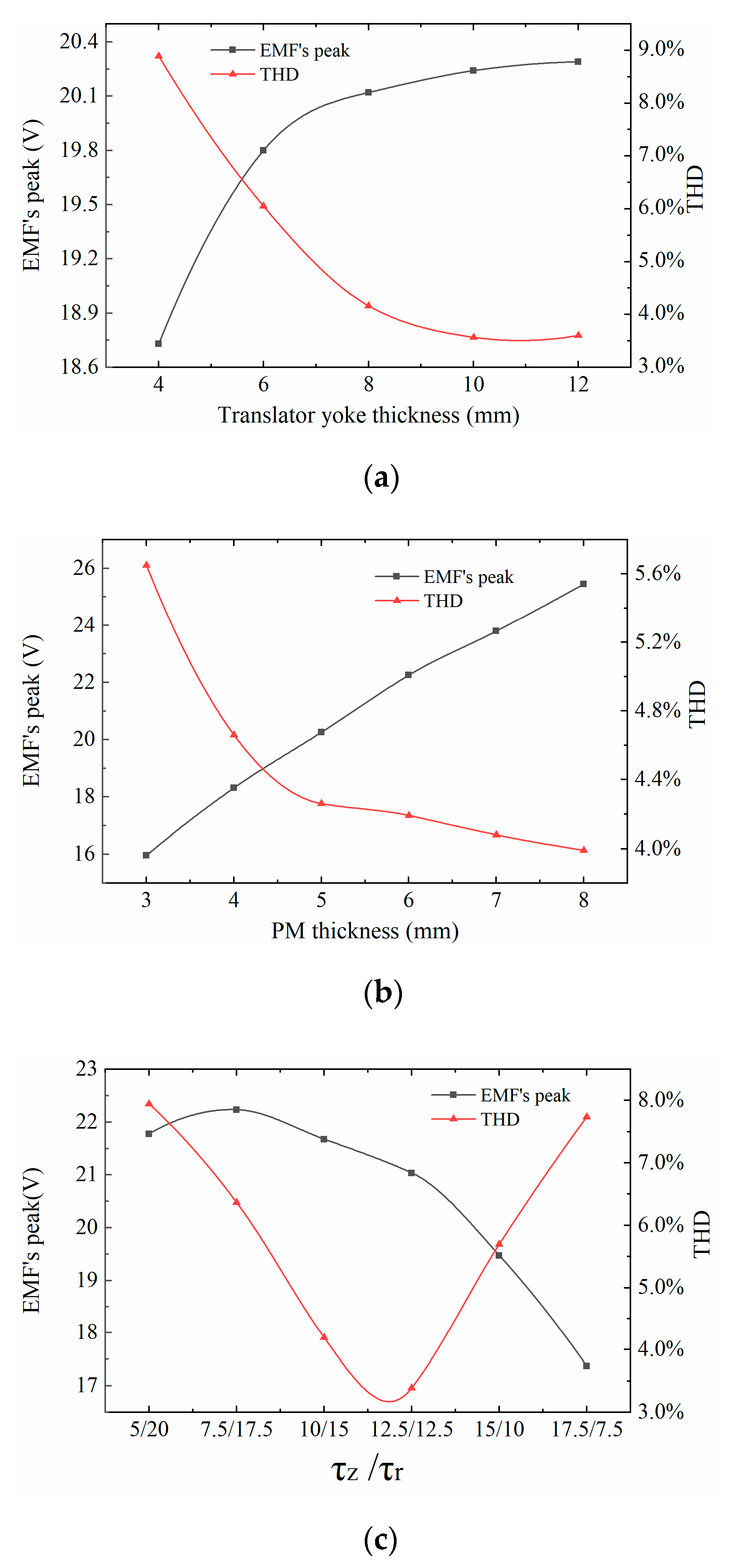
  • The thickness of the PM, the width of the edge tooth, and the axial length ratio of the axial and radial magnetized PM have a greater influence on the peak and the THD of the EMF. With the increase of PM thickness and edge tooth width, the EMF’s peak increases proportionally, and the THD decreases gradually. In the Halbach array, when the length of the radial magnetized PM is closer to the length of the intermediate tooth, the peak of the EMF is larger. The smaller the axial size difference between the axial and radial magnetized PM, the smaller the THD will be. The THD will be the smallest when the axial and radial magnetized PM are equal in size.
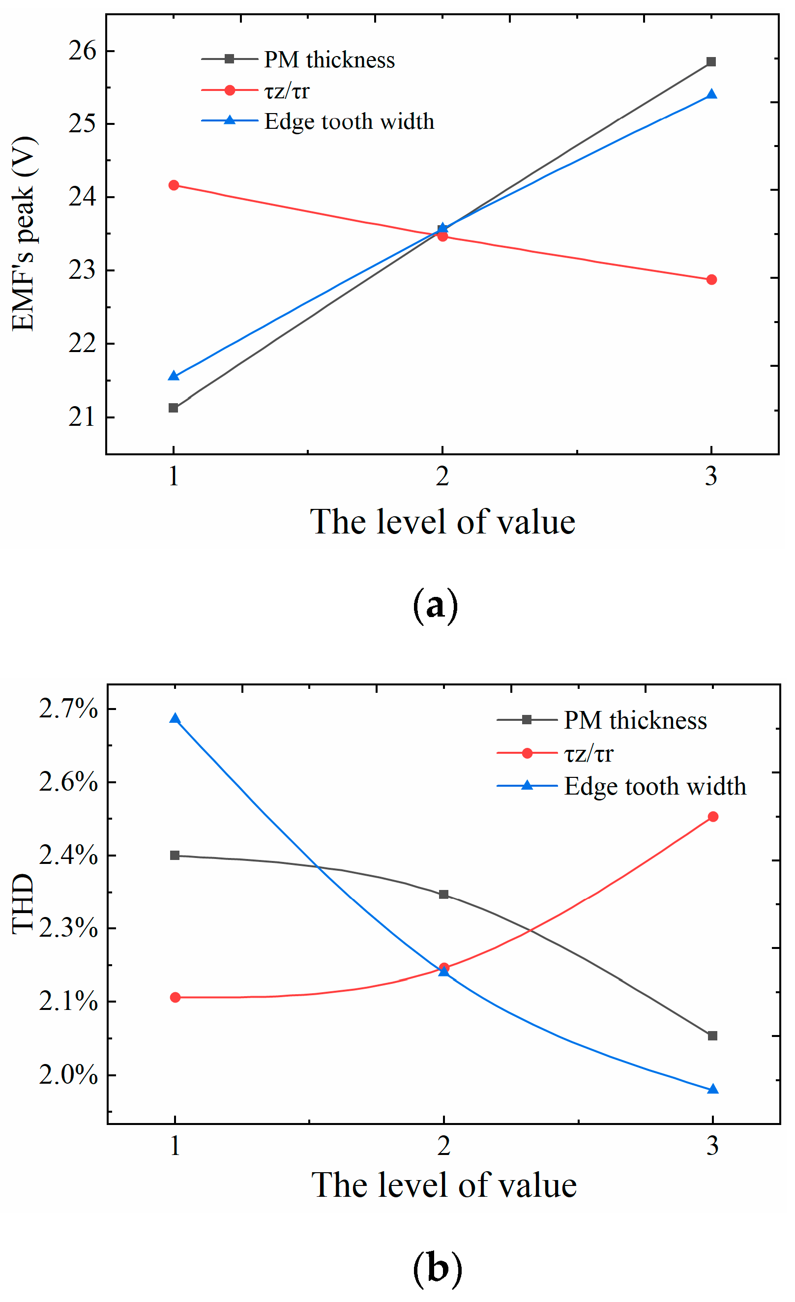
  • The orthogonal design method is used to study the influences of three factors, including the thickness of the PM, the width of the edge teeth, and the ratio of the axial length of the axial and radial magnetized PM. The ideal structural parameters are hM = 7 mm, τ z / τ r = 11.5/13.5, and an edge teeth width of 11 mm. Finally, the optimal combination of PMLG structural parameters is obtained.
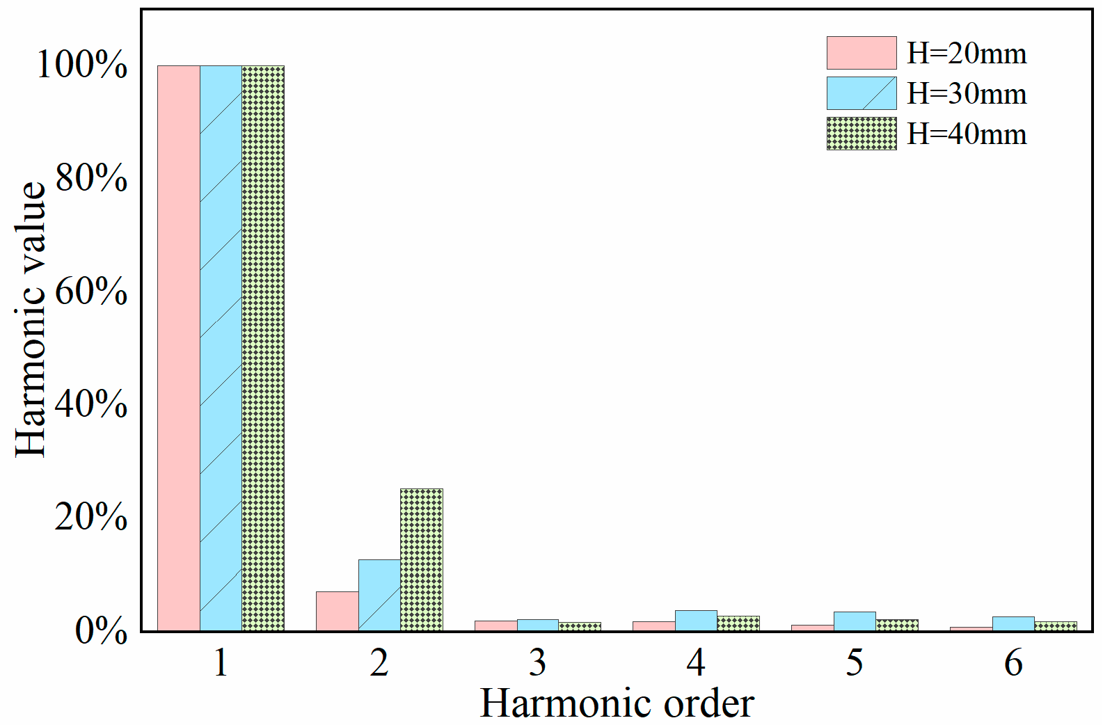
  • The EMF’s peak is related to the movement stroke and frequency; in fact, it increases as the movement stroke and frequency increases. The EMF waveform period increases with the decrease of the motion frequency, which in fact is 0.5 times related to the motion period. The EMF’s THD is correlated with the stroke, that is, the THD is low, and the sine characteristic of the waveform is better when the motion stroke is less than the PM pole distance. The waveform will show some distortions when the motion stroke is greater than the pole distance.

Author Contributions

Conceptualization, X.F. and C.W.; methodology, X.F., C.W. and Z.Z.; software, formal analysis, and investigation, X.F., C.W. and H.M.; data curation, X.F., Z.Z. and H.M.; writing—original draft preparation, X.F., C.W. and H.M.; writing—review and editing, X.F. and Z.Z. All authors have read and agreed to the published version of the manuscript.

Funding

This work was funded by the National Natural Science Foundation of China, grant number 52205271 and Natural Science Foundation of Jiangsu Province, China, grant number BK20190972.

Institutional Review Board Statement

Not applicable.

Informed Consent Statement

Not applicable.

Data Availability Statement

Not applicable.

Conflicts of Interest

The authors declare no conflict of interest.

References

  1. Li, Y.; Luo, K.; Tao, R.; Wang, Z.; Chen, D.; Shao, Z. A new concept and strategy for photovoltaic and thermoelectric power generation based on anisotropic crystal facet unit. Adv. Funct. Mater. 2020, 30, 2002606. [Google Scholar] [CrossRef]
  2. Li, Y.; Wang, Z.; Tao, R.; Fan, Y.; Xu, J.; Yu, L.; Ren, N.; Wu, J.; Chen, D.; Shao, Z. Preparation strategies of p-type cuprous oxide and its solar energy conversion performance. Energy Fuels 2021, 35, 17334–17352. [Google Scholar] [CrossRef]
  3. Dong, F.; An, X.; Li, C. Performance evaluation of wind power industry chain based on three-stage DEA. J. Renew. Sustain. Energy. 2021, 13, 033313. [Google Scholar] [CrossRef]
  4. Wan, Y.; Zheng, C.; Li, L.; Dai, Y.; Esteban, M.D.; López-Gutiérrez, J.S.; Qu, X.; Zhang, X. Wave energy assessment related to wave energy convertors in the coastal waters of China. Energy. 2020, 202, 117741. [Google Scholar] [CrossRef]
  5. Qiu, S.; Liu, K.; Wang, D.; Ye, J.; Liang, F. A comprehensive review of ocean wave energy research and development in China. Renew. Sustain. Energy Rev. 2019, 113, 109271. [Google Scholar] [CrossRef]
  6. Faiz, J.; Nematsaberi, A. Linear electrical generator topologies for direct-drive marine wave energy conversion-an overview. IET Renew. Power Gener. 2017, 11, 1163–1176. [Google Scholar] [CrossRef]
  7. Tan, C.; Lu, Y.; Ge, W.; Li, B.; Lu, J. Depth fuzzy sliding-mode active disturbance rejection control method of permanent magnet linear motor for direct drive system. J. Xi’an Jiaotong Univ. 2023, 1, 1–9, in press. [Google Scholar]
  8. Hamim, M.; Ibrahim, T.; Nor, N.M. Modeling and analyze a single-phase halbach magnetized tubular linear permanent magnet generator for wave energy conversion. In Proceedings of the 2014 International Conference on Power and Energy (PECon), Kuching, Malaysia, 1–3 December 2014; pp. 87–92. [Google Scholar]
  9. Bode, C.; Schillingmann, H.; Henke, M. A free-piston PM linear generator in vernier topology using quasi-Halbach-excitation. In Proceedings of the 2014 International Conference on Electrical Machines (ICEM), Berlin, Germany, 2–5 September 2014; pp. 1950–1955. [Google Scholar]
  10. Li, W.; Chau, K.T.; Jiang, J.Z. Application of linear magnetic gears for pseudo-direct-drive oceanic wave energy harvesting. IEEE Trans. Magn. 2011, 47, 2624–2627. [Google Scholar] [CrossRef] [Green Version]
  11. Pan, J.F.; Li, Q.; Wu, X.; Cheung, N.; Qiu, L. Complementary power generation of double linear switched reluctance generators for wave power exploitation. Int. J. Electr. Power Energy Syst. 2019, 106, 33–44. [Google Scholar] [CrossRef]
  12. Di Dio, V.; Franzitta, V.; Milone, D.; Pitruzzella, S.; Trapanese, M.; Viola, A. Design of bilateral switched reluctance linear generator to convert wave energy. Adv. Mater. Res. 2014, 860, 1694–1698. [Google Scholar]
  13. Feng, N.; Yu, H.; Zhao, M.; Zhang, P.; Hou, D. Magnetic field-modulated linear permanent-magnet generator for direct-drive wave energy conversion. IET Electr. Power Appl. 2020, 14, 742–750. [Google Scholar] [CrossRef]
  14. Zamri, N.A.M.; Ibrahim, T.; Nor, N.M. Direct drive linear generator designs with aluminium spacer and alternate slot winding for wave energy conversion system. Int. J. Adv. Sci. Eng. Inf. Technol. 2017, 7, 1282. [Google Scholar] [CrossRef]
  15. Meng, B.; Xu, H.; Liu, B.; Dai, M.; Zhu, C.; Li, S. Novel magnetic circuit topology of linear force motor for high energy utilization of permanent magnet: Analytical modelling and experiment. Actuators 2021, 10, 32. [Google Scholar] [CrossRef]
  16. Abdalla, I.I.; Ibrahim, T.; Nor, N.M.; Perumal, N. Optimal design of a single-slotted permanent-magnet linear generator for wave energy conversion. Int. J. Appl. Electromagn. Mech. 2018, 56, 21–34. [Google Scholar] [CrossRef]
  17. Tan, C.; Ren, H.; Li, B.; Lu, J.; Li, D.; Tao, W. Design and analysis of a novel cascade control algorithm for braking-by-wire system based on electromagnetic direct-drive valves. J. Frankl. Ins. 2022, 9, 006. [Google Scholar] [CrossRef]
  18. Liu, C.; Chen, R.; Zhang, Y.; Liu, W.; Wang, L.; Qin, J. Design and test of a novel two-body direct-drive wave energy converter. Int. J. Appl. Electromagn. Mech. 2021, 65, 527–544. [Google Scholar] [CrossRef]
  19. Zhang, J.; Yu, H.; Chen, Q.; Hu, M.; Huang, L.; Liu, Q. Design and experimental analysis of AC linear generator with Halbach PM arrays for direct-drive wave energy conversion. IEEE Trans. Appl. Supercond. 2013, 24, 1–4. [Google Scholar] [CrossRef]
  20. Jang, S.M.; Lee, S.H.; Cho, H.W.; Cho, S.K. Design and analysis of helical motion permanent magnet motor with cylindrical Halbach array. IEEE Trans. Magn. 2003, 39, 3007–3009. [Google Scholar] [CrossRef]
  21. Zhou, T.; Huang, Y.; Dong, J.; Guo, B.; Zhang, L. Design and modeling of axial flux permanent magnet machine with yokeless and segment armature using magnetic equivalent circuit. In Proceedings of the 17th International Conference on Electrical Machines and Systems (ICEMS), Hangzhou, China, 22–25 October 2014; pp. 618–623. [Google Scholar]
  22. Arslan, S.; Gurdal, O.; Akkaya Oy, S. Design and optimization of tubular linear permanent-magnet generator with performance improvement using response surface methodology and multi-objective genetic algorithm. Sci. Iran. 2020, 27, 3053–3065. [Google Scholar] [CrossRef] [Green Version]
  23. Fan, X.; Yin, J.; Lu, Q. Design and analysis of a novel composited electromagnetic linear actuator. Actuators 2021, 11, 6. [Google Scholar] [CrossRef]
  24. Tan, Y.; Lin, K.; Zu, J.W. Analytical modelling of Halbach linear generator incorporating pole shifting and piece-wise spring for ocean wave energy harvesting. AIP Adv. 2018, 8, 056615. [Google Scholar] [CrossRef]
  25. Li, B.; Li, D.; Ge, W.; Tan, C.; Lu, J.; Song, A. Design and analysis of a novel cascade control algorithm for braking-by-wire system based on electromagnetic direct-drive valves. China J. Highw. Transp. 2021, 34, 121–132. [Google Scholar]
  26. Li, Z.; Wu, Q.; Liu, B.; Gong, Z. Optimal design of magneto-force-thermal parameters for electromagnetic actuators with Halbach array. Actuators 2021, 10, 231. [Google Scholar] [CrossRef]
  27. Faiz, J.; Amini-Valeshani, S.; Ghods, M. Design and performance of linear Vernier generators—The state of the art and case study. Int. Trans. Electr. Energy Syst. 2021, 31, e12723. [Google Scholar] [CrossRef]
Figure 1. PMLG’s structure.
Actuators 11 00327 g001
Figure 2. Equivalent magnetic circuit method.
Actuators 11 00327 g002
Figure 3. Cloud diagram of magnetic flux intensity.
Actuators 11 00327 g003
Figure 4. Static air gap magnetic density curve of PMLG.
Actuators 11 00327 g004
Figure 5. Effect of translator on EMF. (a) Translator yoke thickness. (b) PM thickness. (c) τ z / τ r
Actuators 11 00327 g005
Figure 6. Effect of tooth width on EMF. (a) Middle tooth width; (b) edge tooth width.
Actuators 11 00327 g006
Figure 7. Effect curve of orthogonal design results. (a) Effect curve of EMF; (b) Effect curve of THD.
Actuators 11 00327 g007
Figure 8. Winding unit and Halbach array of PMLG.
Actuators 11 00327 g008
Figure 9. Detent force diagram of the prototype.
Actuators 11 00327 g009
Figure 10. Prototype test system diagram.
Actuators 11 00327 g010
Figure 11. EMF curve of PMLG under different strokes.
Actuators 11 00327 g011
Figure 12. Harmonic distribution of EMF under different strokes.
Actuators 11 00327 g012
Figure 13. EMF curve of PMLG under different periods.
Actuators 11 00327 g013
Figure 14. Harmonic distribution of EMF under different periods.
Actuators 11 00327 g014
Figure 15. Output performance of simulation and test. (a) Output EMF and current; (b) output EMF and power.
Actuators 11 00327 g015
Table 1. Performance requirements of PMLG.
ParameterValue ParameterValue
Rated voltage UN/V25Stoke H/mm≤40
Rated speed V/m/s0.5Outer diameter Ds_out/mm≤100
Rated frequency fN/Hz10Phase m1
Table 2. Values of structural parameters.
ParameterCode Name Level Value 1Level Value 2Level Value 3
hMA567
τ z / τ r B11.5/13.512.5/12.513.5/11.5
Edge tooth widthC89.511
Table 3. Orthogonal design results.
Operation NumberCombination Amplitude of EMF (V)THD
1A1B1C119.942.62%
2A1B2C221.232.30%
3A1B3C322.212.28%
4A2B1C224.092.06%
5A2B2C325.511.85%
6A2B3C121.043.06%
7A3B1C328.481.64%
8A3B2C123.682.35%
9A3B3C225.382.11%
Table 4. PMLG structure and dimension parameters.
Parameter SymbolValue
StatorOuter diameterDs_out (mm)90
Lengthlef (mm)100
Edge tooth width ω s (mm)11
Groove width ω t (mm)19
Winding turnN660
Winding resistanceRr (Ω)2.82
TranslatorPM thickness hM (mm)7
Length lr (mm)175
Outer diameter Dr_out (mm)38
Radial magnetized PM τ r (mm)13.5
Axial magnetized PM τ a (mm)11.5
Table 5. The output characteristics of PMLG under different frequency and loads.
Load
(Ω)
Frequency
(Hz)
Simulation EMF RMS (v)Test EMF RMS (v)Simulation Output Power (W)Test Output Power (W)
2.558.217.2626.8621.03
3.35.664.9212.769.73
2.54.253.567.165.06
5511.5210.3526.4621.35
3.37.846.8912.189.53
2.55.834.756.624.54
10514.3413.7020.5318.71
3.39.678.689.267.54
2.57.265.865.213.52
15515.5515.1616.0915.28
3.310.459.637.366.31
2.57.856.684.062.93
20516.5016.1213.4912.91
3.310.8210.175.815.15
2.58.157.183.192.52
Publisher’s Note: MDPI stays neutral with regard to jurisdictional claims in published maps and institutional affiliations.

