Article

Design, Manufacturing, and Characterization of Thin, Core-Free, Rolled Dielectric Elastomer Actuators

1
Intelligent Materials Systems Lab, Department of Systems Engineering, Department of Materials Science and Engineering, Saarland University, 66121 Saarbruecken, Germany
2
Intelligent Materials Systems Lab, Center for Mechatronics and Automation Technologies (ZeMA) gGmbH, 66121 Saarbruecken, Germany
*
Author to whom correspondence should be addressed.
Actuators 2021, 10(4), 69; https://doi.org/10.3390/act10040069
Submission received: 11 February 2021 / Revised: 23 March 2021 / Accepted: 26 March 2021 / Published: 30 March 2021
(This article belongs to the Special Issue Electroactive Polymer Actuators)

Abstract

:
In this work, we develop a coreless rolled dielectric elastomer actuator (CORDEA) to be used as artificial muscles in soft robotic structures. The new CORDEA concept is based on a 50 µm silicone film with screen-printed electrodes made of carbon black suspended in polydimethylsiloxane. Two printed silicone films are stacked together and then tightly rolled in a spiral-like structure. Readily available off-the-shelf components are used to implement both electrical and mechanical contacts. A novel manufacturing process is developed to enable the production of rolled actuators without a hollow core, with a focus on simplicity and reliability. In this way, actuator systems with high energy density can be effectively achieved. After presenting the design, an experimental evaluation of the CORDEA electromechanical behavior is performed. Finally, actuator experiments in which the CORDEA is pre-loaded with a mass load and subsequently subject to cycling voltage are illustrated, and the resulting performance is discussed.

1. Introduction

Dielectric elastomers (DEs) have attracted the interest of many researchers due to their large deformations, high energy density and efficiency, low cost, and self-sensing capabilities. In general, a DE consists of a highly deformable polymer film sandwiched between two compliant electrodes, forming a capacitor. When a high voltage is applied to the electrodes, it results in an attractive electrostatic force between them. The resulting normal stress (also called Maxwell stress) leads to a deformation in the transversal direction of the film, due to the incompressibility of the elastomer. DEs can be used as actuators, by exploiting the principle discussed above, or eventually as sensors, since the capacitance information can be related to the mechanical deformation.
Numerous configurations of DE actuators (DEAs) have been presented in the literature, such as strip-in-plane ones [1], stacks [2,3], diaphragms [4], bending ones [5], bowties [6], spiders [7], and rolls [8], to mention few examples. Each configuration offers its unique advantages, which might make it more suitable for a specific class of applications [9]. As an example, strip-in-plane actuators (also shown in Figure 1a,b) are suitable for applications in which a flat form-factor is required, while diaphragm actuators are appropriate when large deformations are needed, and stacks of DEs offer the possibility of generating high forces in a compact volume [10].
Among the many possible types of DEA configurations, rolled DEAs (RDEAs) have received significant consideration in the literature. In a RDEA, the dielectric polymer and the electrodes are tightly wound in a spiral-like or cylindrical form. The application of a voltage across the electrodes produces a radial Maxwell-stress which, in turn, results in an axial expansion of the roll, as shown in Figure 1c,d. Compared to alternative DEA configurations, RDEAs can be designed in a very slender cylindric shape. In this way, they can generate large uniaxial forces and moderate strokes with a very compact form factor. Furthermore, their particular shape makes it possible to bundle together several rolls, thus allowing to design highly energy-dense actuator systems. Among the most promising fields of applications for RDEAs, it is worth mentioning artificial muscle fibers for soft robotics applications [11,12].

1.1. Overview of Existing Works on Rolled DEAs

Since the early 2000s, many RDEA prototypes have been developed and presented in the literature [7]. Conceptually, the various types of RDAEs differ in terms of the adopted dielectric and electrode material, as well as by the presence or the absence of a core element inside the roll. In general, the core may consist of a pre-tensioning spring, a hollow volume, or it can be absent in case the DE-film is tightly rolled as a spiral. A further difference among the several types of RDEAs is the direction of the exerted forces. This feature mainly depends on the buckling stability of the RDEA structure, and can be influenced by both geometry and type of core. Table 1 summarizes some recent relevant works in the field of RDEAs.
Earlier works on RDEAs made use of an acrylic-based material (VHB 4910 or VHB 4905) as a dielectric polymer. In [18,21], a ferroelectric material is used. While the use of those materials as a dielectric leads to a potentially higher energy density compared to others, their limited bandwidth compared to silicones [25] makes them unsuitable for applications where a fast actuation is required. Since we are primarily interested in developing DEA solutions for the activation of a soft tentacle arm, a silicone dielectric is preferred in this work [26]. Advantages of silicone include a faster bandwidth and a higher energy efficiency, at the expense of a smaller deformation range (usually not larger than 100%). Furthermore, the RDEAs must be easily manually manufacturable in a few steps, and consist of a minimum number of components, which are ideally available on the market.
In our previous work [8], we presented an early prototype for a silicone-based RDEA. A commercially available silicone film (Wacker Elastosil 2030) is pre-strained, and an electrode consisting of carbon black suspended in a solution of polydimethylsiloxane (PDMS), solvents, and additives is screen printed onto the film. Wire end ferrules were crimped to the roll and served simultaneously as electrical and mechanical connections. We used commercially available materials in all steps. The core, however, was left as hollow. This led to unutilized space inside the roll. Additionally, wrinkling occurred during the rolling process, since the adopted manufacturing process lacked a support structure for the DE film in some critical manufacturing stages. This resulted in a loss of performance of the RDEA.

1.2. Motivation and Outline

As a compact final design is desirable, a tight winding of the film is required to maximize the utilization of available build volume. In contrast to our previous concept, in this paper, we develop an improved and repeatable manufacturing process for tightly rolled core-free RDEAs (CORDEAs), in which the roll is wound without an inner hollow area or spacers. The process is designed to prevent wrinkling by supporting the DE film at all times, either by an outside frame, an intermediate transfer substrate, or the roll itself during the rolling process. The crimping process is also substantially improved in terms of repeatability, by utilizing a specialized jig to position all components and achieve a defined crimping diameter. After developing the novel prototype concept, an extensive experimental campaign is conducted, aimed at characterizing the electromechanical response of the novel CORDEA. In particular, the performance of both hollow and core-free RDEAs are evaluated and compared, in order to highlight the advantages of the new concept. A first actuator prototype consisting of a CORDEA pre-loaded with a mass is finally assembled, and its actuation performance is characterized for different biasing mass values. From the conducted experiments, it is observed that the novel approach leads to a higher normalized blocking force and a higher volumetric energy density than our previous design since all the available build volume is used in an effective way. The formation of wrinkles is also eliminated, as indicated by the remarkable agreement between the theoretical and measured capacitance values. A comparative evaluation with other silicone-based RDEAs reported in the literature reveals that, given the same total volume occupied by the actuator, we are able to achieve a substantially higher normalized total blocking force (24 mN/mm−2) than previous attempts. This result, in combination with actuation strains of 2.9%, gives an estimated volumetric energy density of 30 mJ/cm3, which is comparable to the maximum values reported in the literature.
The remainder of this paper is organized as follows. The new CORDEA concept is first illustrated in Section 2. The manufacturing process for the new actuators is described in detail in Section 3. Experimental characterization of the electromechanical response of both hollow and core-free RDEAs is presented in Section 4. Finally, concluding remarks are pointed out in Section 5.

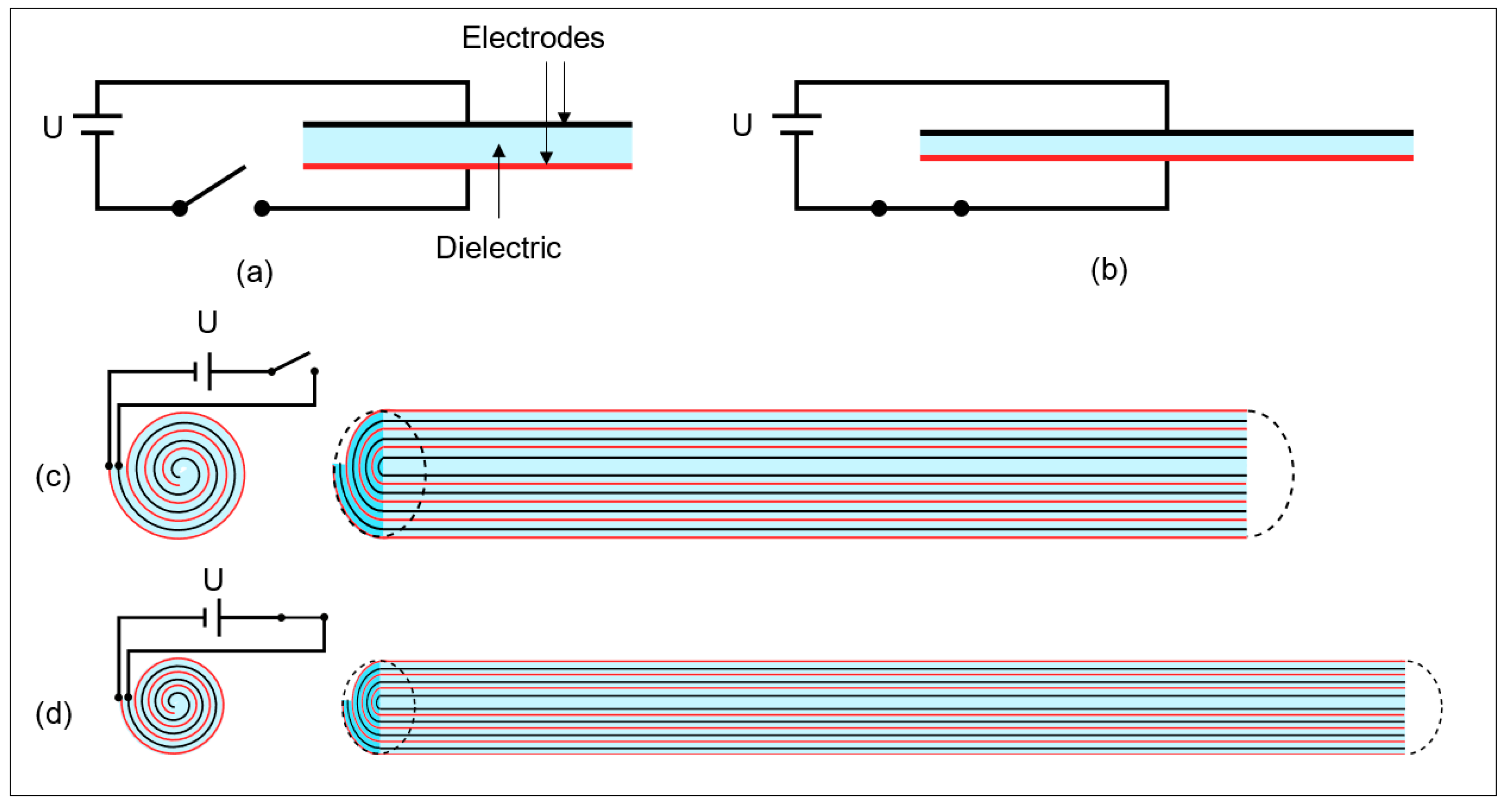
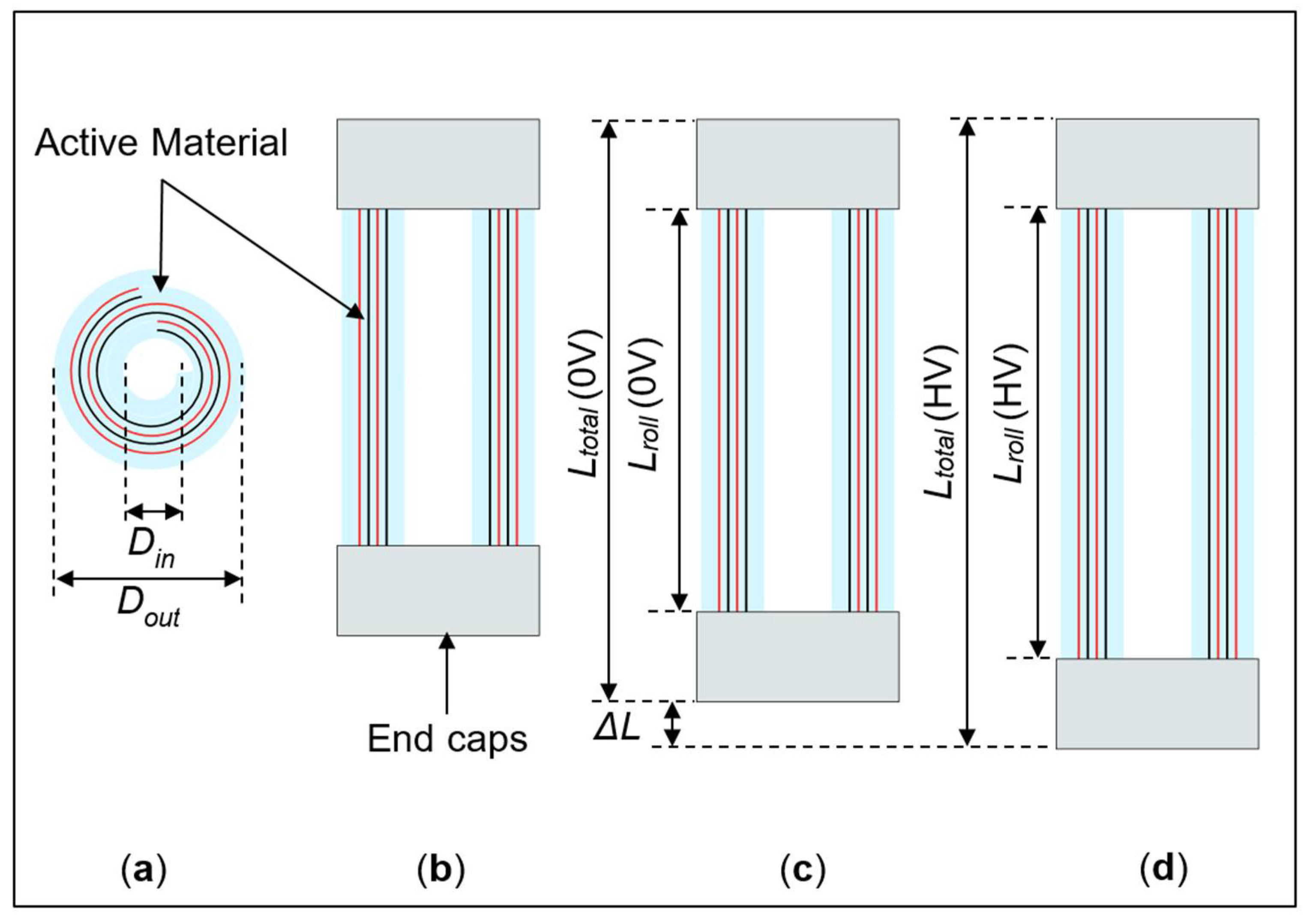
2. Rolled Elastomer Actuator Concept

For implementing the CORDEA, two layers of silicone film are considered. A different electrode pattern is applied to each film, see Figure 2a. The two electrodes are depicted in red and grey for illustrative purposes only, while in reality they are both made out of carbon black. Note that the two electrodes are a mirror image of each other, and also include the areas for implementing the electrical connections. One of the films has a cutout on one corner, for allowing contact to the electrode of the film below. For simplicity, a rectangular electrode geometry is chosen for the active film area. It is remarked how mathematically optimized electrodes could potentially offer even higher strains, compared to regular ones [27]. However, this possibility will be investigated in future works. Both electrodes are stacked on top of each other (Figure 2b), and subsequently rolled (Figure 2c).
Based on the rolling concept described above, both hollow and core-free RDEAs can be manufactured, as described in the corresponding section. Figure 3 shows a simplified cross-sectional view of the stacked films before rolling, as well as a hollow RDEA previously presented and a CORDEA proposed in this work.
By tightly winding the same amount of dielectric material with the cross-sectional area A = 2L2L3, a more compact actuator with similar performance to the hollow RDEA can be built.
For implementing the electrical and mechanical connection of the RDEA, a commercially available wire ferrule made of tin-plated copper is attached in a controlled manner by crimping. The wire ferrule acts both as a mechanical connection, by exerting a radial force onto the inactive portions of the roll and the threaded rod, and as an electrical interface to the contacts exposed at both ends (see Section 3.4 for details). Subsequently, the wire ferrule can be electrically connected by soldering, ring cable lugs, or eventually alligator clips.

3. Manufacturing

The main requirements for the manufacturing process are consistency and simplicity. These goals can be achieved by using off-the-shelf components, a small number of individual parts, and fixtures that allow for exact alignment in all the steps of the process. To make our results reproducible, we will describe the process in detail. First, the preparation of the films is outlined. Afterward, the rolling process previously developed in [8] is shortly reviewed, and the newly developed approach is presented. Finally, the completely new developed crimping process is shown.

3.1. Film Preparation

The film preparation process consists of the following steps:
  • A 50 μm DE film (Wacker Elastosil 2030) is detached from its supporting layer and stretched biaxially by 5% in a device specifically designed for this purpose. The pre-stretch is maintained constant by fixing the film into a rigid metal frame. The pre-stretch is only necessary to prevent the formation of wrinkles during the manufacturing process.
  • Compliant electrodes, consisting of carbon black particles suspended in a mixture of polydimethylsiloxane (PDMS), solvents, and additives, are screen printed onto the film. Many electrode patterns can be printed on the same PDMS membrane, if needed, thus allowing the manufacturing of several CORDEAs at the same time. The optimal printing parameters have been evaluated in previous works [28,29]. In particular, it is determined that a medium-sized mesh of 60 threads per mm and two printed layers result in a low enough resistivity to obtain consistent capacitance measurements. The chosen parameters also represent a good trade-off between a minimal amount of stiffening, due to the addition of material onto the film, and dimensional accuracy of the printed electrodes. Based on experimental investigation, it is determined that the choice of those parameters had no meaningful impact on the blocking force.
  • After the printing of each layer, the films are cured in an oven.
  • The steps above are repeated one more time, but considering this time the mirrored electrode layout.
  • Each electrode is independently tested to check for any defects, by applying a voltage of 3900 V (corresponding to an electric field of 86 V/μm). If an electrical breakdown is detected, the corresponding electrode is marked and discarded in the following manufacturing steps.
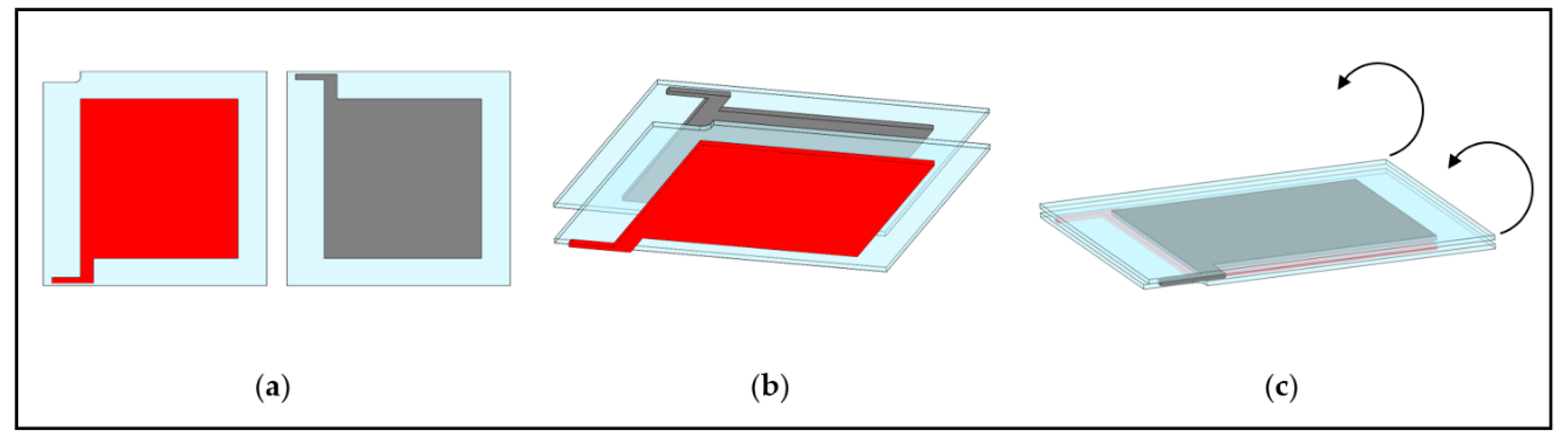
  • The frames are put into a jig, and a hand roller is used to adhere the films onto the support sheets, as shown in Figure 4a.
  • A rolling knife is used to cut the film, as shown in Figure 4b.
  • A scalpel and a stencil are used to cut one of the corners. This allows contacting the inner electrode.
  • Steps 6 and 7 are repeated for the second membrane, so the second electrode is stacked on top of the first one, as shown in Figure 2b.
It is remarked that one can, in principle, print many electrode patterns on the same membrane. In this way, many rolls can be produced at the same time out of the same screen-printing session (see, e.g., Figure 4).

3.2. Previous Rolling Process

The rolling process represents the main improvement of this work concerning RDEA manufacturing. To begin with, we consider two DE films with screen-printed electrodes adhered to a transfer sheet. The process previously developed in [8] is briefly summarized in the following. Figure 5a shows the rolling fixture, and a cross-sectional view of the process is shown in Figure 5b, while a longitudinal cut is shown in Figure 5c.
The edge of the film is manually detached from the transfer sheet and wound by synchronously turning two threaded nylon rods. This process is difficult to reproduce due to the tendency of the film to wrinkle and stick to itself. Since the central area of the film is hollow, the torque introduced by the threaded rods at the ends is transmitted through the roll only by the film itself. Due to the compliant nature of the film, wrinkles are introduced. Such wrinkles can be eventually reduced, or eliminated, by using a manual supporting tool.

3.3. Improved Rolling Process

For the new CORDEAs, we chose a different approach, depicted in Figure 6. In this case, the stack of a transfer plate and two films with printed electrodes is put onto an angled fixture. A PMMA plate is being slid across the corner of the stack, picks up the edge of the films, and forms an initial roll. The sliding process is then continued, until the remaining parts of the films are coiled up and the roll is completely wound.
While our previously developed process requires the use of threaded rods as spacers for the rolling process, the new approach of using an PMMA plate sliding over the edge of the film leads to a roll that forms itself without the use of an external rotating mechanism. The film is supported at all times, thus preventing wrinkling, and no manual tool is needed to guide the roll. This greatly simplifies the manufacturing process, due to a lower number of parts and parameters. The absence of a hollow maximizes the volume utilized by the DE.

3.4. Crimping

Differently from [8], in which the crimping was conducted in a purely manual process, in here we developed a crimping device that allows for a repeatable process. First, the rolled DE and a stop pin with a defined diameter are crimped, as it can be seen in Figure 7a,b. This ensures the right amount of radial displacement, and thus a consistent crimping force. This allows preventing the membrane from being destroyed, while still avoiding that the ferrule slips under tension. Then, the crimping pin is removed and a threaded rod made of nylon is inserted and crimped, as shown in Figure 7c. This process is repeated on the other end of the roll, as well. During the crimping process, a small inactive portion of the film is left between the active area and the wire ferrules. This is done in order to prevent the crimping process from affecting the active area, by compressing the film between opposed electrodes, and thus causing a premature electrical breakdown.
By employing the above-defined process, we were able to manually roll and crimp four CORDEAs with defined dimensions in one hour. A picture of two manufactured RDEAs, namely a hollow and a core-free one with identical film and electrode geometry, is shown in Figure 8. Using a scalpel, a thin slice of each RDEA is cut and observed in a transmitted light microscope to examine their inner structure, as shown in Figure 8.
From these pictures, it can be noted that the CORDEA has a smooth surface and interior structure without wrinkles. Furthermore, it is much more compact and simpler to roll, and no hollow area is present inside of the roll. By further reducing the inner inactive area of the film, even higher utilization of a given volume can be potentially achieved.

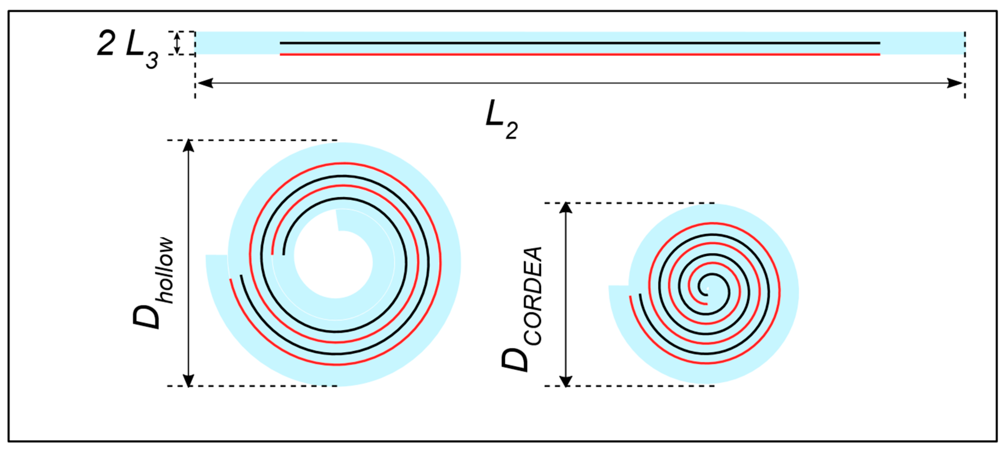
3.5. Film and Electrode Parameters

The design parameters and measured quantities for one hollow specimen and two CORDEA specimens are reported in Table 2, in conjunction with Figure 9. The geometric parameters and their strains occurring during the manufacturing process are discussed in detail in Appendix A.
Table 2. Dimensions of the films and electrodes.
Design ParametersSymbolUnitHollowCORDEA Spec. 1CORDEA Spec. 2
Film length (a)Lfilm,1,pre(mm)7875
Film width (a)Lfilm,2,pre(mm)7899
Film Thickness (a)L3,pre(µm)4545
Electrode length (a)Lel,1,pre(mm)5360
Electrode width (a)Lel,2,pre(mm)5876
Inactive inner Part (a)Linac,in(mm)1010
Inactive outer Part (a)Linac,out(mm)1013
Active Length (b)Lel,1,0(mm)5057
Diameter (c)D(mm)4.13.33.6
Length of roll (c)Lroll,0(mm)6066.564.3
Number of Windings (d)N(-)121418
(a) design parameter, based on 5% biaxial pre-strain, see Figure 9. (b) calculated, based on 0% longitudinal and 5% circumferential strain, see Figure 9b. (c) measured after the rolling process, see Figure 9b. (d) determined by transmitted light microscopy, see Figure 8.
Figure 9. Relevant dimensional parameters of the RDEAs. Schematic of the Figure 5 right after the screen-printing (a), and relaxed state after rolling (b).
Actuators 10 00069 g009

4. Experimental Results

In the following, the hollow RDEA and CORDEA specimen 1 are compared and their electro-mechanical behavior is characterized, in order to evaluate the feasibility of the new concept and quantify its performance. Subsequently, CORDEA specimen 2 is additionally tested in an actual actuation test setup, whereby it acts against a weight as a constant force bias under a varying voltage.

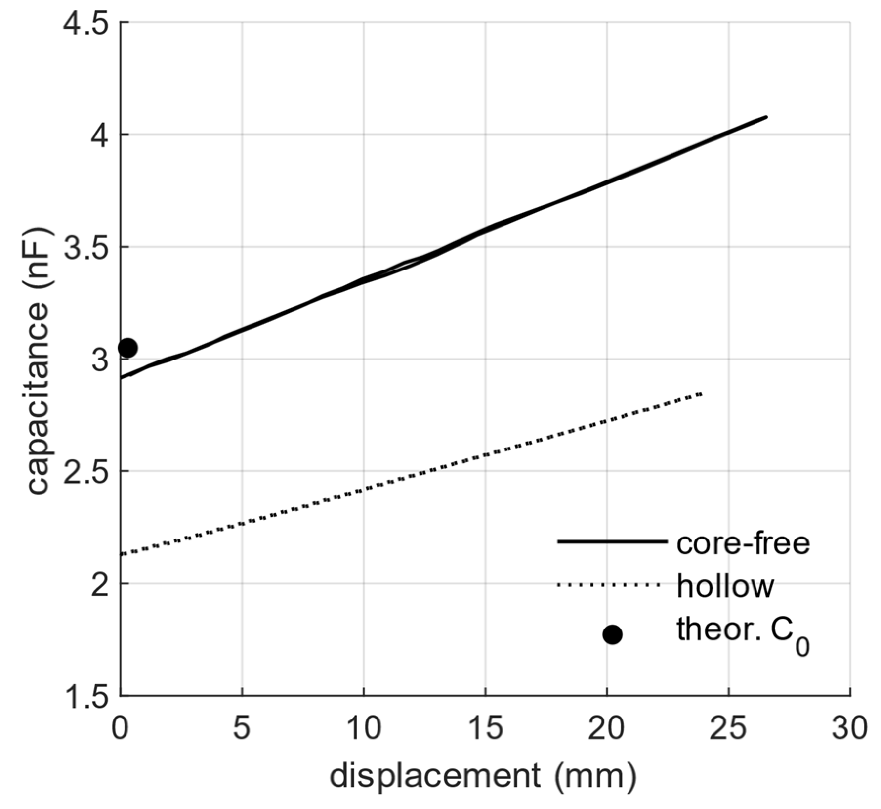
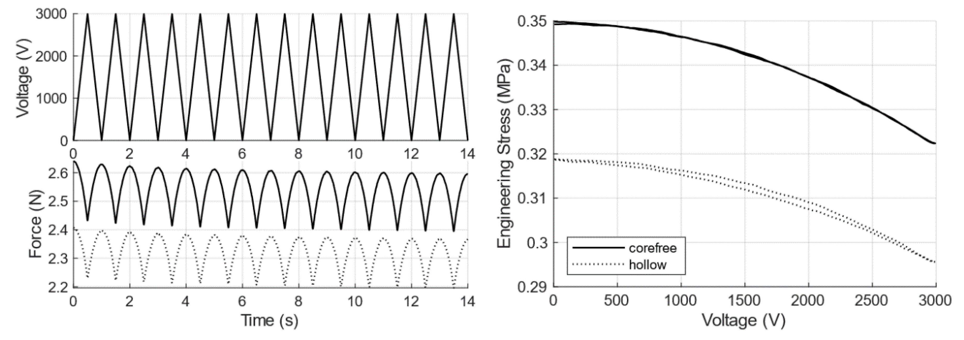
4.1. Electro-Mechanical Performance Comparison between Hollow RDEA and CORDEA Specimen 1

In this section, electro-mechanical characterization of the RDEAs is performed. Results are presented in terms of the typical [20,30,31] measurements used to characterize the behavior of a DEA, namely stress-strain response at different applied voltages, blocking force tests, and capacitance-strain measurements. To characterize the performance of the RDEAs, the experimental setup shown in Figure 10 is used. During each experiment, the RDEA displacement is controlled with an Aerotech ACT165DL Linear Actuator, while a high voltage is applied to the electrodes via TREK Model 5/80 High Voltage Amplifier. The resulting RDEA force is acquired via a FUTEK LSB303 Load cell (25 lb). Only for the experiments with no applied voltage, a further electrical capacitance measurement is implemented via an impedance meter (Rohde and Schwarz HAMEG HM8118 LCR Bridge). In this way, a comprehensive characterization of the RDEA electromechanical response can be achieved. A NI-9149 CompactRIO FPGA chassis with appropriate IO-modules manages the DAQ, while data post-processing is done using LabView and Matlab on a Windows Computer.
As a subsequent step, a hollow specimen and a CORDEA are evaluated and compared. Both rolls are manufactured with the same film and electrode geometry, according to Table 2, but differ in terms of rolling configuration. A triangular displacement is applied at a frequency of 0.1 Hz, with an amplitude ranging from 0 up to 40% of the unstretched electrode length Lel,1,0, while the force is measured. The experiment is repeated twice, with the RDEA subjected to a constant voltage of 0 V and 3000 V, respectively. For 0 V, the capacitance is also measured via the LCR meter (Figure 11).
To further investigate the performance and compare the CORDEA to the hollow RDEA, the acquired displacement and force data are normalized. The engineering strain ε1, based on the initial roll length Lroll,0 and the measured roll length Lroll(t), as well as the engineering stress δ1(t), based on the measured force and the initial cross-sectional area of the film, are given as follows [32]:
ε 1 ( t ) = L r o l l ( t ) L r o l l , 0 L r o l l , 0 ,
σ 1 ( t ) = F ( t ) 2 L f i l m , 2 , 0 L f i l m , 3 , 0 .
The factor 2 on the denominator of (2) arises due to fact that two silicone films are stacked. The resulting stress-strain curves are reported in Figure 12. Note how the curves show a moderate hysteresis, as a result of the viscoelasticity of the DE material and the electrode.
In practice, the effective actuation performance of a DEA can be determined by inspecting the size of the gap between the low and high voltage curves [1]. If the RDEA is configured in a setup in which it is working against a constant force F, e.g., when a mass is attached on the lower end of a hanging RDEA, a constant engineering stress is induced (cf. (2)), and as a result the membrane will elongate to a length of Lroll,mass(0 V). As an actuation voltage of Uact is applied, the RDEA softens and extends to a length of Lroll,mass(Uact). The resulting difference in displacement can again be normalized as an actuation strain ε1,act in relation to LRoll,mass(0 V), as:
ε 1 , a c t = L r o l l , m a s s ( U a c t ) L r o l l , m a s s ( 0   V ) L r o l l , m a s s ( 0   V ) = ε 1 ( U a c t ) ε 1 ( 0   V ) ε 1 ( 0   V ) + 1 .
The estimation for the actuation strain shown in Figure 12 is based on a fifth-order polynomial fit (0.9961 < R2 < 0.9966) of the loading and unloading branches of the 0 V and 3000 V stress-strain-curves, respectively. We remark how, in this special case, the fit is not solely used to interpolate the data, but also to extract the average system behavior, which does not account for viscoelastic losses. Therefore, the R2 value is not strictly representative of the fit accuracy, because it also accounts for dynamic phenomena that we are explicitly excluding from our analysis.
As it can be seen, the actuation strain, and thus the potential actuation performance of the CORDEA, is larger compared to our previous hollow design. It is also noted that a larger preload leads to a bigger actuation strain below a stress of 0.25 MPa. This can be reasonably explained by considering the higher electric field strength at a given voltage, due to a lower film thickness at higher elongations
Next, electrical capacitance measurements for 0 V are conducted. According to the datasheet of the measurement device (HAMEG HM8118 LCR Bridge), the accuracy for the corresponding measurement range and settings is at least 0.12%. We verified the influence of the experimental setup by measuring the capacitance at 0% strain multiple times. The reported capacitances were consistently measured with a relative error of less than 1%. Figure 13 shows a linear relation between capacitance and displacement for both RDEAs. From this figure, it can be concluded that RDEAs can be effectively used as self-sensing actuators.
To calculate a theoretical capacitance value, we can simplify the spiral-geometry by imagining multiple nested cylindrical capacitors. The well-known formula for a cylindrical capacitor with length L, inner radius Ri, outer radius Ro, vacuum permittivity ϵ0, and relative permittivity ϵr is given as:
C c y l = ϵ 0 ϵ r 2 π L ln ( R o R i ) .
By introducing the film thickness t = R0Ri, the above equation can be written as:
C c y l = ϵ 0 ϵ r 2 π L ln ( R i + t R i ) = ϵ 0 ϵ r 2 π L ln ( 1 + t R i ) .
If the film thickness t is small compared to the inner radius R i , as for the RDEA case, the argument of the natural logarithm is close to one, and thus it can be approximated by the first term of the Mercator series:
C c y l ϵ 0 ϵ r 2 π L R i t .
Note how the above formula is equivalent to the one describing a parallel-plate capacitor with electrodes surface area 2πLRj. Since the total capacitance of a RDEA can then be written as the sum of the capacitances of all the imagined cylindrical capacitors, we can apply approximation (6) multiple times, and thus obtain the following equivalent formula for the RDEA:
C t h e o r , 0 = ϵ 0 ϵ r 2 L e l , 1 , 0 L e l , 2 l 0 L f i l m , 3 , 0 = 3.03   nF .
The multiplicative factor 2 in (7) arises due to the fact that two stacked film layers exist in the system. For a 0% strain configuration, the measured capacitance for the CORDEA is 90% of the theoretically determined value, while the hollow RDEA only achieved 74% of such a value. It can be assumed that this is due to the formation of wrinkles during the rolling process because the film is lacking support. If air is trapped between the films, it unavoidably leads to a lower equivalent capacitance due to its lower relative permittivity as well as to the increased distance between the electrodes. This wrinkling effect can also explain the difference in the slope of the stress-strain curves in Figure 12. Wrinkled portions of the film get straightened out instead of being stretched, thus leading to an apparent decrease in stiffness. All those effects highlight the benefits of the novel CORDEA design. Additionally, the equivalent serial resistance of CORDEA specimen 1 has been measured by the LCR meter. It ranges between 23.5 kΩ and 28.6 kΩ, depending on the actual strain value. For further info on the intrinsic conductivity of the silicone material, instead, the reader may refer to [28,29].
To further verify the feasibility of the CORDEA as an actuator, blocking force measurements are conducted. In this case, both RDEAs are kept under a constant strain of 40%, while a triangular voltage signal between 0 V and 3000 V at 1 Hz is applied. From those measurements, a stress-voltage graph can be computed (Figure 14).
As expected, increasing the voltage from 0 V to 3000 V effectively softens the RDEAs, thus reducing the force by about 0.16 N for the hollow RDEA and 0.2 N for the CORDEA at a constant displacement of 40%. The raw data shows an overall decrease in blocking force over repeating cycles. This can be explained by the relaxation of the RDEAs due to their viscoelasticity.

4.2. A CORDEA Working against a Constant Force

As a final experiment, an actuator system based on the novel CORDEA is assembled and characterized. For this purpose, the CORDEA specimen 2 is measured using the setup in Figure 15a. Constant forces of 0.2 N, 1.2 N, and 2.2 N are applied by attaching weights and simultaneously measured using a FUTEK LSB303 Load cell (25 lb). The displacement is measured by a Keyence LK-G157 laser displacement sensor. An aerostatic bearing guides the moving assembly of the setup. A sinusoidal voltage signal with a low frequency of 0.1 Hz is used as the control input. The low frequency is chosen to suppress oscillations of the system, thus approximating a quasi-static loading condition. The measured CORDEA length in Figure 15b shows an elongation as the voltage is increased, and a contraction as the voltage decreases, as expected. Creep dynamics can also be observed in the initial phase, due to the viscoelastic behavior of the material. The actuation strains, defined by (3), depending on the voltage, are shown in Figure 15c. An increase in actuation strain for higher pre-strains is expected, since higher strains correspond to a thinner DE-film, and thus a higher electrical field strength for a given voltage. The achieved actuation strains and their prediction based on the measurement of specimen 1 are reported in Table 3.
It is important to note that those strains can be improved considerably by combining the CORDEA with a bistable biasing mechanism, similar to the mechanisms shown in [1]. This further optimization of the actuation performance, however, falls beyond the scope of this paper and will be investigated in future research.

4.3. Discussion

To evaluate the CORDEA performance based on our measurements, and compare them with existing works, a variety of normalized performance metrics are computed according to the definitions provided in Appendix B. Two different kinds of strains and blocking forces each are computed, first in relation to the bulk material of the rolls, i.e., εroll and δroll, and second in relation to the outer dimensions of the actuator, i.e., εtotal and δtotal. The approximate gravimetric energy density eroll is evaluated in relation to the roll material itself, while the volumetric energy density Utotal is related to the outer dimensions of the actuator.
The most important characteristics and performance metrics for the CORDEAs presented here, as well as other silicone-based RDEAs found in the literature, are summarized Table 4. For all performance measures, the maximum reported value found in the literature is reported or calculated.
From the reported data, it can be seen that the CORDEAs exhibit comparatively high blocking stresses, both in relation to the roll material itself (27.6 mN mm−2) as well as in relation to its outer dimensions (24.0 mN mm−2), while exerting a low strain of 2.9%. The estimate for its gravimetric energy density has a similar magnitude to our previous work, as well as typical values reported for comparable RDEAs, while the magnitude of the volumetric energy density is considerably improved by the novel tight rolling process, and is the highest one compared to other silicone-based RDEAs. The linear and repeatable capacitance measurements also show promising results for future self-sensing implementation. Additionally, all raw materials, including the dielectric film, are commercially available. By employing a simple and scalable screen-printing process for electrode deposition, as well as a simple rolling process, it is possible to manually fabricate a high volume of low-cost CORDEAs.

5. Conclusions

In this paper, a new thin coreless rolled dielectric elastomer actuator (CORDEA) concept has been developed, and its performance has been shown. Compared to existing concepts based on acrylic dielectrics, the new silicone-based design promises higher bandwidth and energy efficiency. The utilized materials are commercially available as off-the-shelf components, which differentiates our new approach from other recent works. In contrast to our previous work, the utilization of cross-sectional area, and thus potential volumetric energy density, could be increased from 0.16 mJ/cm3 to 0.30 mJ/cm3. The slender shape of this tension-mode actuator also allows designing highly compact bundles of artificial muscles, which are attractive for future applications in soft robotics. With an actuation strain of 2.9% and an actuation stress of 27.6 mN mm−2, this concept is a promising foundation for further research.
One of the next steps of our research will consist in analyzing and improving the characteristics of the CORDEAs, in terms of performance, reliability, and reproducibility. The utilization of nonlinear biasing elements, either externally coupled or as an inherent component of the roll, will be also explored in order to further extend the actuation strain. At the same time, a control-oriented model of the CORDEA will be developed to better understand and predict the behavior of the new actuator. Applications in soft robotics tentacle arms will finally be explored.

Author Contributions

Conceptualization, investigation, writing—original draft preparation: J.K.; methodology: J.K., J.P.; resources: B.F.; writing—review and editing, supervision: G.R., S.S., D.B.; project administration: G.R., S.S., S.N., P.M.; funding acquisition: S.S. All authors have read and agreed to the published version of the manuscript.

Funding

The authors gratefully acknowledge the support of the Deutsche Forschungsgemeinschaft (DFG, German Research Foundation) through Priority Program SPP 2100 “Soft Material Robotic Systems” (Projects: SE704/6-1, RI3030/1-1).

Acknowledgments

We want to thank the company WACKER for providing the ELASTOSIL 2030 DE-Film for this study.

Conflicts of Interest

The authors declare no conflict of interest.

Appendix A. Strains in the Material during the Manufacturing Process

The following processes concerning the dimensions and strains are assumed to occur during the manufacturing process. A non-compressible DE-Film with a thickness of L3 = 50 µm is pre-strained biaxially by 5%, which results in the following pre-strains: ε1,pre, in the direction of actuation, ε2,pre in the direction of rolling, and ε3,pre normal to the film. The numerical values of such strains are given by:
ε 1 , p r e = 5 % ,         ε 2 , p r e = 5 % ,         ε 3 , p r e = 1 ( 1 + ε 1 , p r e ) ( 1 + ε 2 , p r e ) 1 = 9.3 % .
The electrodes are then screen printed onto the films. The thickness of the electrodes can be assumed as negligible, compared to the one of the DE. The films are adhered to the transfer-sheets and then cut into pieces with the appropriate dimensions. After the subsequent rolling process, the roll is allowed to relax in the direction of actuation, for which a pure-shear behavior is assumed [26]. The strains, now related to an unloaded roll, are denoted as ε1,0 in the direction of actuation (axial), ε2,0 in the direction of rolling (along the spiral), and ε3,0 normal to the film (radial):
ε 1 , 0 = 0 % ,         ε 2 , 0 = ε 2 , p r e = 5 % ,         ε 3 , 0 = 1 ( 1 + ε 1 , 0 ) ( 1 + ε 2 , 0 ) 1 = 4.8 % .
Thus, the axial length, spiral-wise length and thickness of the film Lfilm,1,pre, Lfilm,2,pre and Lfilm,3,pre, respectively, as well as the electrode axial and spiral-wise lengths, Lel,1,0 and Lel,2,0 respectively, all in an unloaded state of the RDEAs, can be calculated as:
L f i l m , 1 , 0 = L f i l m , 1 , p r e 1 + ε 2 , p r e ,       L f i l m , 2 , 0 = L f i l m , 2 , p r e ,         L f i l m , 3 , 0 = L 3 ( 1 + ε 3 , 0 ) ,
L e l , 1 , 0 = L e l , 1 , p r e 1 + ε 2 , p r e ,       L e l , 2 , 0 = L e l , 2 , p r e .

Appendix B. Calculation of Performance Measures

In general, the performance of a DEA is expressed in terms of its maximum stroke and its maximum blocking force. To effectively compare different actuator configurations, however, it is appropriate to normalize those absolute values. From a continuum mechanics point of view, it makes sense to calculate a strain εroll from the stroke ΔL and the roll lengths Lroll(0 V) and Lroll(HV), illustrated in Figure A1c,d, as
ε r o l l = Δ L L r o l l ( 0 V ) = L r o l l ( H V ) L r o l l ( 0 V ) 1 .
The blocking force ΔF can be normalized to obtain an equivalent blocking stress Δσroll, using the thickness of a single layer L3, the number of layers before rolling n, and the total unwound length of the film L2 (see also Figure 3), as:
Δ σ r o l l Δ F n L 2 L 3 .
From an application point of view, however, the performance of the actuator in relation to its outer dimensions is of interest. Thus, it makes more sense to normalize the stroke ΔL in relation to the total length of the pre-stretched actuator, including the wire end ferrules, or end-caps, as follows:
ε t o t a l = Δ L L t o t a l ( 0 V ) = L t o t a l ( H V ) L t o t a l ( 0 V ) 1 ,
and to calculate a blocking stress Δσtotal in relation to the total area, including the hollow core of the actuator, as
Δ σ t o t a l 4 Δ F π D o u t 2 .
Figure A1. Dimensions on a diagram of a generic RDEA for determining normalized performance metrics. Cross-sectional cut (a) and longitudinal cut (b) of the unstretched roll, longitudinal cut of the pre-stretched roll at 0 V (c), and longitudinal cut of the actuated roll at high voltage (d).
Actuators 10 00069 g0a1
Although the energy density of DEAs is often discussed in the literature, no consistent and precise formula is available for its calculation. In [24], a linear stress-strain relation is assumed, and a gravimetric energy density is calculated as
e = 1 2 m a F B δ ,
with mass of the actuator ma, blocking force FB, and free displacement δ. Using intensive instead of extensive quantities, this equation can be rewritten based on the density of the DE material ρ, as follows
e r o l l = 1 2 ρ Δ σ r o l l ε r o l l .
In a similar way, a measure for the volumetric energy density Utotal is of practical interest as well. It can be defined as
U t o t a l = 1 2 Δ σ t o t a l ε t o t a l .
It is noted that those energy densities are based on the assumption of ideal linear elasticity. While most materials used in DEAs exhibit a nonlinear viscoelastic behavior, it is observed that the measured actuation strains are generally small (<10%). Therefore, a linear approximation serves as an estimate to evaluate the feasibility of a concept, and to allow simple comparison between different approaches.

References

  1. Hau, S.; Bruch, D.; Rizzello, G.; Motzki, P.; Seelecke, S. Silicone based dielectric elastomer strip actuators coupled with nonlinear biasing elements for large actuation strains. Smart Mater. Struct. 2018, 27, 074003. [Google Scholar] [CrossRef]
  2. Kovacs, G.; Düring, L.; Michel, S.; Terrasi, G. Stacked dielectric elastomer actuator for tensile force transmission. Sens. Actuators A Phys. 2009, 155, 299–307. [Google Scholar] [CrossRef]
  3. Carpi, F.; Salaris, C.; De Rossi, D. Folded dielectric elastomer actuators. Smart Mater. Struct. 2007, 16. [Google Scholar] [CrossRef]
  4. Nalbach, S.; Banda, R.M.; Croce, S.; Rizzello, G.; Naso, D.; Seelecke, S. Modeling and Design Optimization of a Rotational Soft Robotic System Driven by Double Cone Dielectric Elastomer Actuators. Front. Robot. AI 2020, 6, 1–14. [Google Scholar] [CrossRef]
  5. Kofod, G.; Wirges, W.; Paajanen, M.; Bauer, S. Energy minimization for self-organized structure formation and actuation. Appl. Phys. Lett. 2007, 90, 89–91. [Google Scholar] [CrossRef]
  6. White, P.; Latscha, S.; Yim, M. Modeling of a dielectric elastomer bender actuator. Actuators 2014, 3, 245–269. [Google Scholar] [CrossRef]
  7. Kornbluh, R.D.; Pelrine, R.; Pei, Q.; Heydt, R.; Stanford, S.; Oh, S.; Eckerle, J. Electroelastomers: Applications of Dielectric Elastomer Transducers for Actuation, Generation and Smart Structures. In Proceedings of the Smart Structures and Materials 2002: Industrial and Commercial Applications of Smart Structures Technologies, San Diego, CA, USA, 17–21 March 2002; Volume 4698, pp. 254–270. [Google Scholar]
  8. Kunze, J.; Prechtl, J.; Bruch, D.; Nalbach, S.; Motzki, P.; Seelecke, S.S.; Rizzello, G. Design and fabrication of silicone-based dielectric elastomer rolled actuators for soft robotic applications. In Proceedings of the Electroactive Polymer Actuators and Devices (EAPAD) XXII, Online Only, USA, 27 April–8 May 2020; Bar-Cohen, Y., Anderson, I.A., Shea, H.R., Eds.; SPIE: Bellingham, WA, USA, 2020; p. 80. [Google Scholar]
  9. Kornbluh, R. Fundamental configurations for dielectric elastomer actuators. In Dielectric Elastomers as Electromechanical Transducers; Carpi, F., De Rossi, D., Kornbluh, R., Pelrine, R., Sommer-Larsen, P., Eds.; Elsevier Science: Amsterdam, The Netherlands, 2008; pp. 79–90. ISBN 9780080474885. [Google Scholar]
  10. Wang, N.F.; Cui, C.Y.; Guo, H.; Chen, B.C.; Zhang, X.M. Advances in dielectric elastomer actuation technology. Sci. China Technol. Sci. 2018, 61, 1512–1527. [Google Scholar] [CrossRef]
  11. Lau, G.-K.; Chin, Y.-W.; Heng, K.-R.; Lau, G.-K.; Chin, Y.-W.; Heng, K.-R. Soft Actuators and their Fabrication for Bio-Inspired Mobile Robots. In Proceedings of the 1st International Conference on Progress in Additive Manufacturing, Singapore, 26–28 May 2014; Research Publishing Services: Singapore, 2014; Volume 6, pp. 185–192. [Google Scholar]
  12. Gupta, U.; Qin, L.; Wang, Y.; Godaba, H.; Zhu, J. Soft Robots Based on Dielectric Elastomer Actuators: A Review. Smart Mater. Struct. 2019, 28, 103002. [Google Scholar] [CrossRef]
  13. Pei, Q.; Pelrine, R.; Stanford, S.; Kornbluh, R.; Rosenthal, M. Electroelastomer rolls and their application for biomimetic walking robots. Synth. Met. 2003, 135–136, 129–131. [Google Scholar] [CrossRef]
  14. Rajamani, A.; Grissom, M.; Rahn, C.; Ma, Y.; Zhang, Q. Wound roll dielectric elastomer actuators: Fabrication, analysis and experiments. In Proceedings of the 2005 IEEE/RSJ International Conference on Intelligent Robots and Systems, Edmonton, AB, Canada, 2–6 August 2005; Volume 13, pp. 2587–2592. [Google Scholar]
  15. Zhang, R.; Lochmatter, P.; Kunz, A.; Kovacs, G. Spring roll dielectric elastomer actuators for a portable force feedback glove. In Proceedings of the Smart Structures and Materials 2006: Electroactive Polymer Actuators and Devices (EAPAD), San Diego, CA, USA, 27 February–2 March 2006; Volume 6168, p. 61681T. [Google Scholar]
  16. Pelrine, R.; Kornbluh, R.; Pei, Q.; Joseph, J. High-speed electrically actuated elastomers with strain greater than 100%. Science 2000, 287, 836–839. [Google Scholar] [CrossRef] [PubMed]
  17. Kovacs, G.; Ha, S.M.; Michel, S.; Pelrine, R.; Pei, Q. Study on core free rolled actuator based on soft dielectric EAP. In Proceedings of the Electroactive Polymer Actuators and Devices (EAPAD), San Diego, CA, USA, 10 March–13 March 2008; Volume 6927, p. 69270X. [Google Scholar]
  18. Ren, K.; Liu, S.; Lin, M.; Wang, Y.; Zhang, Q.M. A compact electroactive polymer actuator suitable for refreshable Braille display. Sens. Actuators A Phys. 2008, 143, 335–342. [Google Scholar] [CrossRef]
  19. Benslimane, M.Y.; Kiil, H.E.; Tryson, M.J. Dielectric electro-active polymer push actuators: Performance and challenges. Polym. Int. 2010, 59, 415–421. [Google Scholar] [CrossRef]
  20. Kiil, H.-E.; Benslimane, M. Scalable industrial manufacturing of DEAP. Electroact. Polym. Actuators Devices 2009 2009, 7287, 72870R. [Google Scholar] [CrossRef]
  21. Levard, T.; Diglio, P.J.; Lu, S.G.; Rahn, C.D.; Zhang, Q.M. Core-free rolled actuators for Braille displays using P(VDF-TrFE-CFE). Smart Mater. Struct. 2012, 21. [Google Scholar] [CrossRef]
  22. Lau, G.K.; Lim, H.T.; Teo, J.Y.; Chin, Y.W. Lightweight mechanical amplifiers for rolled dielectric elastomer actuators and their integration with bio-inspired wing flappers. Smart Mater. Struct. 2014, 23. [Google Scholar] [CrossRef]
  23. Zhao, H.; Hussain, A.M.; Duduta, M.; Vogt, D.M.; Wood, R.J.; Clarke, D.R. Compact Dielectric Elastomer Linear Actuators. Adv. Funct. Mater. 2018, 28, 1–12. [Google Scholar] [CrossRef]
  24. Chen, Y.; Zhao, H.; Mao, J.; Chirarattananon, P.; Helbling, E.F.; Hyun, N.; Seung, P.; Clarke, D.R.; Wood, R.J. Controlled flight of a microrobot powered by soft artificial muscles. Nature 2019, 575, 324–329. [Google Scholar] [CrossRef] [PubMed]
  25. Kornbluh, R.; Pelrine, R. High-Performance Acrylic and Silicone Elastomers. In Dielectric Elastomers as Electromechanical Transducers; Carpi, F., De Rossi, D., Kornbluh, R., Pelrine, R., Sommer-Larsen, P., Eds.; Elsevier Science: Amsterdam, The Netherlands, 2008; pp. 33–42. [Google Scholar]
  26. Prechtl, J.; Kunze, J.; Nalbach, S.; Seelecke, S.S.; Rizzello, G. Soft robotic module actuated by silicone-based rolled dielectric elastomer actuators: Modeling and simulation. In Proceedings of the Electroactive Polymer Actuators and Devices (EAPAD) XXII, Online Only, USA, 27 April–8 May 2020; Bar-Cohen, Y., Anderson, I.A., Shea, H.R., Eds.; SPIE: Bellingham, WA, USA, 2020; p. 79. [Google Scholar]
  27. Chen, F.; Liu, K.; Wang, Y.; Zou, J.; Gu, G.; Zhu, X. Automatic design of soft dielectric elastomer actuators with optimal spatial electric fields. IEEE Trans. Robot. 2019, 35, 1150–1165. [Google Scholar] [CrossRef] [Green Version]
  28. Fasolt, B.; Hodgins, M.; Seelecke, S. Characterization of screen-printed electrodes for dielectric elastomer (DE) membranes: Influence of screen dimensions and electrode thickness on actuator performance. Electroact. Polym. Actuators Devices 2016 2016, 9798, 97983E. [Google Scholar] [CrossRef]
  29. Fasolt, B.; Hodgins, M.; Rizzello, G.; Seelecke, S. Effect of screen printing parameters on sensor and actuator performance of dielectric elastomer (DE) membranes. Sens. Actuators A Phys. 2017, 265, 10–19. [Google Scholar] [CrossRef]
  30. Wei, K.; Domicone, N.W.; Zhao, Y. Electroactive liquid lens driven by an annular membrane. Opt. Lett. 2014, 39, 1318. [Google Scholar] [CrossRef] [PubMed]
  31. Rizzello, G.; Naso, D.; York, A.; Seelecke, S. A Self-Sensing Approach for Dielectric Elastomer Actuators Based on Online Estimation Algorithms. IEEE/ASME Trans. Mechatron. 2017, 22, 728–738. [Google Scholar] [CrossRef]
  32. Rizzello, G.; Loew, P.; Agostini, L.; Fontana, M.; Seelecke, S. A lumped parameter model for strip-shaped dielectric elastomer membrane transducers with arbitrary aspect ratio. Smart Mater. Struct. 2020. [Google Scholar] [CrossRef]
Figure 1. Working principle of a strip-in-plane dielectric elastomer actuator (DEA) and a rolled dielectric elastomer actuator (RDEA), both without applied voltage (a,c) and with applied voltage (b,d). The views of the RDEA depicted in (c,d) are based on a radial cut on the left, and on a longitudinal cut on the right.
Actuators 10 00069 g001
Figure 2. Schematic of films with a printed electrode (a) the layering topology (b) and the final stack with the rolling direction (c). One of the electrodes is depicted in red for illustrative purposes. Note the cut corner on the lower film, which allows for electrically contacting the upper film, and the L-shaped contacts.
Actuators 10 00069 g002
Figure 3. Simplified cross-section of dielectric elastomer (DE) material with electrodes before and after rolling. Flat stacked films (top), hollow RDEA (bottom-left), and coreless rolled dielectric elastomer actuator (CORDEA) (bottom-right) at the bottom.
Actuators 10 00069 g003
Figure 4. Detail of the transfer process (a) and the cutting process (b).
Actuators 10 00069 g004
Figure 5. Picture (a) and schematic (b,c) of the rolling process according to our previous work. The cross-sectional view is shown in (b) and longitudinal cut in (c). Note the hollow section in the middle of the roll, which is not supported during the rolling process, and also decreases the utilization of the available volume.
Actuators 10 00069 g005
Figure 6. Picture (a) and schematic (b) of the new rolling process. It can be noted that the absence of a hollow core maximizes the volume utilized by the DE.
Actuators 10 00069 g006
Figure 7. Schematic depiction of the crimping process. One end of the rolled DEA with the exposed L-shaped contacts and a crimping stop pin with a defined diameter is inserted into the ferrule (a). Radial crimping pliers are used to crimp the ferrule (b). Finally, the crimping stop pin is removed, and the threaded nylon rod is crimped (c).
Actuators 10 00069 g007
Figure 8. Comparison of a hollow RDEA and a CORDEA. View in transmitted light microscopy of a thin slice of the rolls on the right.
Actuators 10 00069 g008
Figure 10. Picture of the experimental setup. The lead wires connect to the high voltage amplifier or the LCR-bridge, depending on the experiment which is conducted.
Actuators 10 00069 g010
Figure 11. Prescribed displacement (upper part), the measured forces for 0 V (blue) and 3000 V (red) (center part), and capacitance for 0 V (lower part) of the CORDEA specimen 1 over time.
Actuators 10 00069 g011
Figure 12. Stress plotted against strain for the hollow and core-free versions of the RDEAs (left-hand side) and the actuation strain (right-hand side). The actua-tion strain is calculated based on a fifth-order polynomial fitted on the loading and unloading branches of the 0 V and 3000 V stress-strain-curves, respec-tively.
Actuators 10 00069 g012
Figure 13. Measured capacitance for both RDEAs and theoretical initial capacitance C0 based on (4).
Actuators 10 00069 g013
Figure 14. Blocking force measurements of both RDEAs. Raw data on the left, normalized data for the last cycle on the right.
Actuators 10 00069 g014
Figure 15. The experimental setup for measuring the characteristics of specimen 2 of the CORDEA (a). The applied voltage signal and the measured length plotted over the time for an attached weight that exerts a force of 2.17 N, corresponding to an engineering stress of 230 kPa, are shown in (b). The resulting actuation strain depending on the voltage for different constant loads is depicted in (c). The circles represent the expected strain based on the measurements of CORDEA specimen 1 shown in Figure 12.
Actuators 10 00069 g015
Table 1. Overview of existing works on rolled DEAs.
YearDE-MaterialElectrode MaterialCoreActuation Mode
Pei et al. [13]2003acrylic“carbon-based”springbending, push, pull
Rajamani et al. [14]2005acrylic carbon greasespringpush
Zhang et al. [15]2006acrylic carbon grease [16]spring and telescoping rodpush, pull
Kovacs et al. [17]2008interpenetrated polymer networkcarbon powder core-freepull
Ren et al. [18]2008ferroelectric terpolymerconductive polymer springpush
Benslimane et al. [19]/Kiil et al. [20]2010silicone silvercore-freepush, pull
Levard et al. [21]2012ferroelectric terpolymerconductive polymer hollowpush
Lau et al. [22]2014siliconegraphite powder hollowpull
Zhao et al. [23]2018silicone carbon-nanotubeshollowpush
Chen et al. [24]2019silicone carbon-nanotubeshollowpush
Kunze et al. [8]2020silicone (Wacker Elastosil 2030)carbon black suspended in PDMShollowpull
this work2021silicone (Wacker Elastosil 2030)carbon black suspended in PDMScore-freepull
Table 3. Comparison of measured and expected strains.
Eng. StressMeasured StrainExpected Strain Relative Deviation
22 kPa2.22%2.25%1.3%
126 kPa2.66%2.71%1.8%
230 kPa2.88%3.18%9.4%
Table 4. Comparison of RDEAs based on silicone.
Kiil et al. [20]Lau et al. [22]Zhao et al. [23]Kunze et al. [9]This Work
Actuation Modepush, pull (a)pullpushpullpull
Dielectric Materialsilicone (Wacker Elastosil RT 625)silicone (BJB TC-5005)silicone (mixture)silicone (Wacker Elastosil 2030)Silicone (Wacker Elastosil 2030)
Dielectric Manufacturing Processesroll-to-roll coatingdraw castingspin castingcommercially availablecommercially available
Electrode Materialsilvergraphite powder (TIMREX KS6)carbon-nanotubescarbon black in PDMScarbon black in PDMS
Corecore-free (pull), hollow (push)hollowhollowhollowcore-free
Electrode Deposition Processvacuum metallizationgraphite powder “smearing”CNT stampingscreen-printingscreen-printing
Parameters
Initial Film ThicknessLfilm,3,0(µm)4027.5 to 3527 to 515050
Relative Permittivityεr(1)3.13.0-2.82.8
Dielectric Densityρ(kg/L)1.1-1.031.11.1
Number of initial Layers (-)241022
Outer DiameterDouter(mm)3011<124.13.3/3.6
Inner DiameterDinner(mm)15 (b)9.5 (b)~52.7~0
Total lengthLtotal(mm)100546–128387/89
Active lengthLroll(mm)6030.56–125050/57
Performance Measuressafemax
Maximum VoltageUmax(V)250036006000100030003000
Roll Strainεroll(%)2.3 (c)6.5 (c)6.1 (d)9.8 (c)(2.9) (e)2.9 (f)
Total Strainεtotal(%)1.5 (c)4.2 (c)4.0 (d)9.8 (c)(2.5) (e)2.5 (f)
Roll Blocking Stress (g)Δσroll(mN mm−2)1630-8.223.027.6
Total Blocking Stress (g)Δσtotal(mN mm−2)1222-5.513.024.0
Grav. Energy Density (g)eroll(mJ/g)0.170.89-0.39(0.31) (e)0.36
Vol. Energy Density (g)Utotal(mJ/cm3)0.090.47-0.27(0.16) (e)0.30
(a) Only data for the pull-mode actuator is available in the literature. (b) Calculated based on outer diameter and known active cross-sectional area. (c) Unloaded. (d) Pre-strained by biasing spring-element. (e) Estimated from stress-strain curves. (f) Pre-strained by a constant force of 2.17 N by 36%. (g) Approximated, see Appendix B for details.
Publisher’s Note: MDPI stays neutral with regard to jurisdictional claims in published maps and institutional affiliations.

