
Gain-Scheduled Control of Asymmetric Thrust Magnetic Bearing

1
State Key Laboratory of Technologies in Space Cryogenic Propellants, Technical Institute of Physics and Chemistry, Chinese Academy of Sciences, Beijing 100190, China
2
University of Chinese Academy of Sciences, Beijing 100049, China
*
Author to whom correspondence should be addressed.
Actuators 2021, 10(12), 329; https://doi.org/10.3390/act10120329
Submission received: 31 October 2021
/
Revised: 6 December 2021
/
Accepted: 9 December 2021
/
Published: 13 December 2021
(This article belongs to the Special Issue New Control Schemes for Actuators)
Abstract
:The thrust position of the magnetic levitation rotor can be changed, bringing convenience to the practical application of cold compressors. This paper derives the mathematical model of asymmetric thrust magnetic bearings for a cold compressor and analyzes the changes in the system characteristics with the equilibrium position. By constructing PID controllers associated with the structural parameters of the magnetic bearing, the adaptive adjustment of the control parameters under different balanced position commands is realized. The simulation and experimental results prove that the gain-scheduled control method proposed in this paper can achieve a robust stability of the rotor in the range of 50 to 350 μm, and not at the cost of the response speed, adjustment time, and overshoot. The research results have reference significance for the structure design of asymmetric thrust magnetic bearings and play an important role in the commissioning and performance improvement of cold compressors.
1. Introduction
Nowadays, it is prevalent to apply cold centrifugal compressors to reduce the pressure of the sub-cooling tank in order to obtain 2 K superfluid helium on a large scale [1]. Grease-lubricated and gas bearings make it challenging to meet the low temperature, negative pressure, and high-speed operating conditions of cold compressors. The active magnetic bearing (AMB) uses electromagnetic force to suspend the rotor in space without friction and lubrication. Thus, it has universal advantages, such as no wear, high speed, and a long life [2]. Furthermore, AMB can improve the stability and efficiency of the compressor by adjusting its supporting characteristics. It is the best choice for the rotor support assembly of the cold compressor in the current superfluid helium refrigeration system [3].
The cold compressor is the critical component, and its efficiency is critical to the production of superfluid helium. In the case of the same rotation speed, the efficiency improvement of the magnetic levitation compressor can be achieved by actively controlling the axial position of the rotor to reduce the tip clearance [4]. However, most existing control methods [5,6,7] are based on a linear model. They have fixed control parameters, which only guarantee stability in a single equilibrium position or within a narrow range. In the past, we tested cold compressors with conventional control methods. When the balanced position was adjusted to be close to 30 μm, the response speed started to slow down; when the amplitude modulation was close to 100 μm, the rotor vibrated back and forth.
The unique working environment of the cold compressor determines that only one axial position is impossible to be perfect. The impeller is at an ultra-low temperature near 3 K, whereas the drive end is located in a room-temperature environment, so the rotor spans a temperature zone close to 300 K. Thermal expansion and contraction under the working conditions change the blade tip clearance, which has already been assembled at room temperature. The tip clearance can ensure the highest efficiency at a low temperature, resulting in very narrow operating conditions. For safety reasons, a large tip clearance is often reserved in reality, even though this is at the expense of efficiency. In our previous experience, the tip clearance has been set as large as 200 μm, and the efficiency is only close to 50%. Even so, there are still other problems. During the commissioning process of the superfluid helium system, the cold compressor needs to be shut down repeatedly. The impeller connected to the rotor at room temperature is quickly reheated, whereas the volute in the cold box can be kept low. A larger tip clearance than 200 μm is required to prevent the impeller and the volute from bonding and damage caused by thermal deformation, which will affect the usual start next time. In response to these problems, it is necessary to propose a control strategy to ensure that the rotor can quickly and robustly stabilize at any specified position within a large range, which is very important for the healthy and efficient operation of the compressor.
The balanced (tracking) position of the controlled object can be adjusted by modifying the reference command. Much research on this aspect comes from the positioning of lathe machining tools. Smirnov A. et al. [8] realize step, cone, and convex tracking in the range of 30 μm. Xudong Guan et al. [9] track different signals in the field of 70 μm. The literature [10] and [11] use advanced algorithms to achieve a higher tracking accuracy than ordinary algorithms. Overall, these studies focus more on improving the tracking accuracy, speed, and shape. On the other hand, they pay less attention to tracking a more extensive range, since the actuator can move synchronously with the tool it clamps.
Conversely, it is hoped that the adjustable range is extensive, since the tip clearance range of the cold compressor is as large as approximately 200 μm [4]. Apart from that, it also needs to have a strong anti-interference ability and have a minor overshoot when adjusting the balanced position in order to reduce the airflow impact. It may be possible to change the equilibrium position in a small range, but it is hard to achieve that within the entire clearance range. Suppose the balanced position is forcibly modified in a big step. In that case, the existing system will deviate significantly from the theoretical model, and the originally suitable controller may cause a poor response and even an unstable system. The literature [12] has studied how different balanced positions affect the tip clearance and ultimately influence the compression efficiency. Still, the clearance alteration in the research is not online, and the adjustment principle and methods of the control parameters under different clearances are not explained.
This paper derives the nonlinear model of the asymmetric thrust AMB for a vertical cold compressor, analyzes the system changes with the different balanced positions, and proposes a gain-scheduled controller whose control parameters automatically adjust with the balance position changing. The simulation and experimental results show that, compared with the parameter-fixed controller, the gain-scheduled control method ensures the stability and good performance of the AMB system, even if the balanced position changes in a wide range of 50 to 350 μm.
2. Model
2.1. Cold Compressor
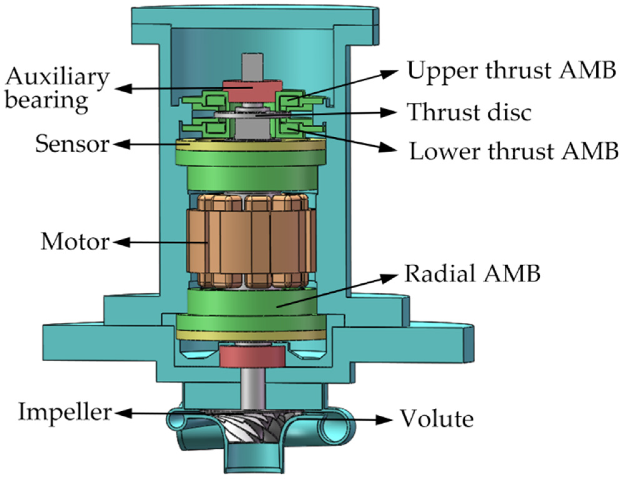
The schematic diagram of the cold compressor in the superfluid helium refrigeration system is shown in Figure 1.
The working medium at the impeller is liquid helium of approximately 3 K. The rotor far away from the impeller is at room temperature to meet the working condition of the permanent magnet synchronous motor and the AMB. The motor stands in the middle position and it is used for driving the rotor rotating at high speed. Two radial AMBs lie in the upper and lower ends of the motor, and the thrust AMB is located at the upper position of the rotor. They are applied to support all of the degrees of freedom of the rotor. Two inductive displacement sensors are placed outside the two radial AMBs to measure the radial and axial displacement.
The compressor is designed as a vertical structure to be fitted conveniently on the refrigeration system. Compared with the lower AMB, the upper AMB needs to bear the rotor gravity. In the regular operation, the balanced position of the compressor rotor is set in the center and remains unchanged. In this most common situation, if we expect that the currents of the upper and lower AMB are almost close, then we can only choose to make the axial AMB into a ‘large upper and small lower’ structure. The original intention of the asymmetric design is only to improve the conventional operating state of the compressor. The structure is not necessary for the application of the gain-scheduled control method proposed in this article.
The detailed design principle of the thrust AMB can be referred to [13]. In the actual assembly and testing, the air gap of the thrust AMB is further reduced based on the original design to facilitate the stability control of the rotor. As a result, the corresponding bias current and the heat generation of the thrust AMB can be decreased further. The structure diagram of the thrust AMB is shown in Figure 2, and its critical structural parameters are listed in Table 1. Moreover, the physical structure parameters of the rotor and radial AMB are listed in Table 2.
2.2. Non-Linear Electromagnetic Force
The electromagnetic force fa generated by the single magnetic pole is related to the coil current i and the distance s between the stator and rotor [2]:
where μ0 is the vacuum permeability, N denotes the coil turns, A is the magnetic pole area, and k is the AMB structure parameter, which does not change with the instantaneous state of the system.
Use the subscripts u and d to denote the upper and lower thrust AMB, respectively, and introduce the structural parameters ku and kd of the thrust AMB:
Combining Formulas (1) and (2), the resultant electromagnetic force of the upper and lower thrust AMB can be expressed as [3]:
where xm and xp denote the unilateral air gap of the thrust AMB and the auxiliary bearing, respectively, the specified balanced position is labeled x0 (0 < x0 < 2xp), the bias current is labeled i0, the instantaneous distance of the rotor from the bottom end of the auxiliary bearing is indicated by x, and i indicates the instantaneous control current.
The first-order approximation of the Taylor series near the equilibrium (x = x0, i = 0) for the Formula (3) is presented:
The resulting external force f on the rotor should be:
In the above formula, ki and kx are the current stiffness and displacement stiffness, respectively. They are the two critical parameters related to the AMB geometry, the bias current, and the reference position.
According to Formula (4), the electromagnetic force fa includes a constant force part fa0, not varying with the instantaneous state of the system. Even when the rotor is balanced at the physical center, and even if the thrust AMB is asymmetric, the term is not zero. According to the design ideas mentioned above, when the rotor is suspended at the center, fa0 should be exactly the same as the gravity of the rotor.
It should be noted that the purpose of constructing the linearization model is to explain the variation regular of the model characteristics with the equilibrium position and thus put forward the automatic adjustment strategy of PID parameters. However, the simulation calculation will retain the nonlinear form of the model.
2.3. Model Analysis
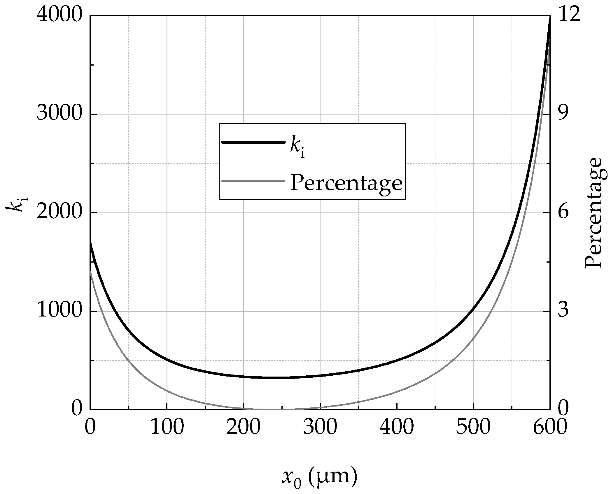
When the equilibrium position is specified between 0 μm and 600 μm, the variation and their percentage changes in ki and kx characterizing the electromagnetic force model are illustrated in Figure 3 and Figure 4, respectively. It should be noted that the magnitudes of ki, kx, and fa0 are also affected by the bias current, according to Formula (4). However, to highlight the variation characteristics with different positions, the bias current remains unchanged, with a value of 0.85 A, as shown in Table 1.
These figures show that the ki and kx are not symmetrical at the center of 300 μm. The change near the upper AMB is much more dramatic than that near the lower AMB due to the larger geometry of the upper AMB. These figures depict that the two parameters remain almost unchanged within the range of 100 μm, deviating downward from the center. However, ki and kx increase rapidly, and their slopes increase notably when the deviation increases. When the balanced position deviates from the scope of (200, 300) by 100 μm, the percentage change in ki and kx reaches 55% and 85%, respectively. It can be inferred from Figure 4 that the parameter-fixed controller may maintain the system as stable within the range of 200 to 300 μm. Still, beyond this range, the response performance is likely to deteriorate rapidly. The results are confirmed in the following simulation experiment.
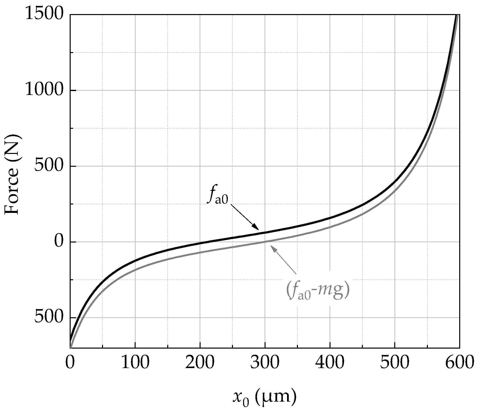
The solid black line in Figure 5 shows the variation characteristics of fa0 with the balanced position. As shown in Formula (4), fa0 is a constant force generated by the asymmetrical AMB. When the rotor is balanced at the center, fa0 is not zero but is supposed to be equal to the rotor gravity, according to the previous design expectations. At this equilibrium point, the coil current of the upper and lower AMB should be close. When the balanced position deviates from the center, the resultant force of the electromagnetic force and the gravity is not zero. Thus, additional current is needed to offset the resultant force represented by the gray curve. The figure shows that the resultant force increases with the deviation. The increasing rate of the force close to the upper AMB is more significant than the lower.
It should be mentioned that the feature analysis of these figures is based on Formula (1), ignoring magnetic flux leakage and core magnetization. The application of the Taylor expansion formula in Formula (4) makes the error tend to increase as x0 moves away from the AMB center. However, it does not prevent us from analyzing the qualitative law of the problem.
3. Controller Design
The research applies an incomplete differential PID controller Gc in the following form:
where Kp, Ki, and Kd are the proportional gain, integral gain, and derivative gain, respectively. The derivative time constant Td is also introduced to prevent the controller from infinitely amplifying high-frequency noise signals.
The supporting characteristics of the magnetic suspension rotor in the closed-loop system depend on the AMB, rotor, controller, and other electronic control systems. In the following, the manuscript derives the physical relationship between the control parameters and the stiffness and damping of the closed-loop system and then uses it as the basis to recommend the value ranges of Kp, Ki, and Kd.
The rotor displacement signal x is captured by the sensor and then transmitted to the controller in the closed-loop feedback system. Afterward, it is calculated and converted into the control current i within an appropriate range through the power amplifier to drive the electromagnet coil. The relationship between x and i can be expressed as:
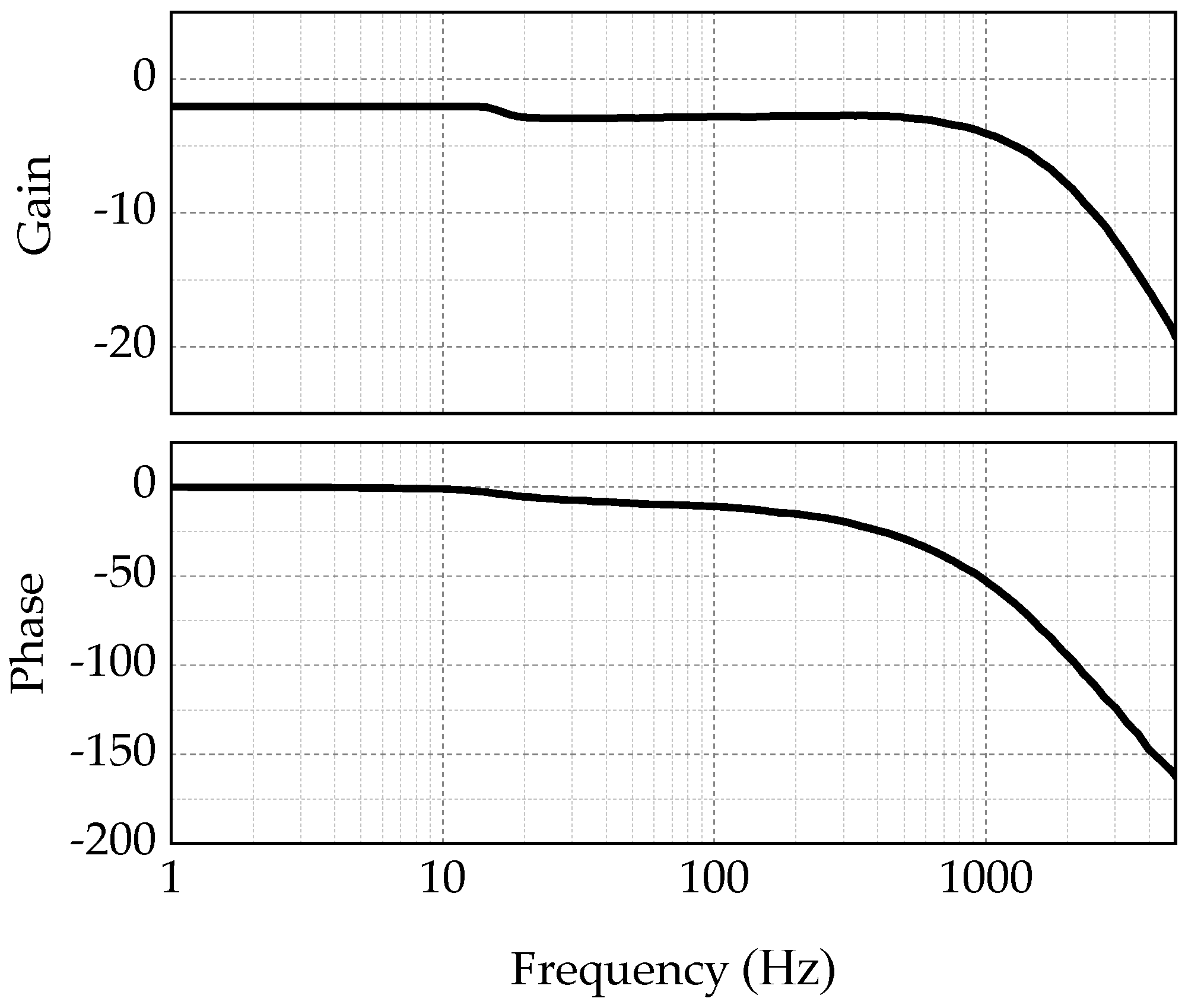
where Ga is the power amplifier’s transfer functions and Gs is the sensor’s. The sweep frequency test shown in Figure 6 displays that the gain of the power amplifier is 0.79 and that the bandwidth is approximately 2.3 kHz. The sensor gain is 20,000 V/m, and the bandwidth of the anti-aliasing filter in the signal processing circuit is 3.3 kHz. The bandwidth of both the power amplifier and the sensor is quite large, so their transfer functions can be simplified into a constant to highlight clearly the relationship between the control parameters and the system supporting performance.
According to Newton’s second law, the force analysis in the axial direction of the rotor is presented as:
Substituting Formulas (7) and (8) into Formula (5) and employing Fourier transform:
If ke denotes the stiffness and de denotes the damping, the Fourier transform of the dynamic equation of the mass-spring-damping system is:
Using simultaneous equations from Formulas (6) and (9), and then comparing with the Formula (10), the equivalent stiffness and equivalent damping of the closed-loop system are:
The cut-off frequency of the differential term in Formula (6) is related to the operating frequency of the compressor, which is approximately 200 Hz. It is easy to prove that Ki and Kd in Formula (11) have little effect on the stiffness and thus can be ignored during the initial estimation stage when the working frequency is below 200 Hz,
Define the stiffness ratio β = ke/kx, and the stiffness coefficient should be greater than 1 to stabilize the rotor. However, excessive stiffness requires a high-bandwidth power amplifier and may cause magnetic field saturation. Therefore, according to (13):
The design standards of compressors [14] and AMBs [15] require the system damping ratio within the operating range to be greater than 20% to obtain a better static and dynamic response performance. However, a large damping ratio will result in the amplification of the noise and the saturation of the control signal. Combining the damping ratio formula with the Formula (14) gives:
According to our debugging experience, the integral effect increases as the proportional coefficient increases. Thus,
γ is assigned as 400 both in the simulation and experiment according to our experience.
3.1. Parameter-Fixed PID Controller
Let us set β 1.5 and ξ 0.75, and introduce these parameters in Table 1 into Formulas (15)–(17). Suppose the rotor is balanced at the AMB center; then, Kp, Kd, and Ki can be calculated. These parameters are listed in Table 3.
Under the parameter-fixed controller, the variation curve of the stiffness ratio and the relative damping coefficient with the balanced position is shown in Figure 7.
The figure indicates that β decreases rapidly as the balanced position deviates from the center. At approximately 170 and 380 μm, the system stiffness starts to be less than the displacement stiffness, and, as a consequence, the system may exhibit a poor response performance. If the deviation continues to increase, when the equilibrium position is less than 47 μm or greater than 545 μm, the stiffness ke begins to decay to a negative value. Negative stiffness means that the characteristic root of the closed-loop system will move from the left half-plane to the real axis, and the rotor cannot remain stable anymore. When the balanced position moves from the center to the magnetic poles at both ends, the rotor is more likely to fall into the unstable area close to the larger upper axial magnetic bearing.
3.2. Gain-Scheduled PID Controller
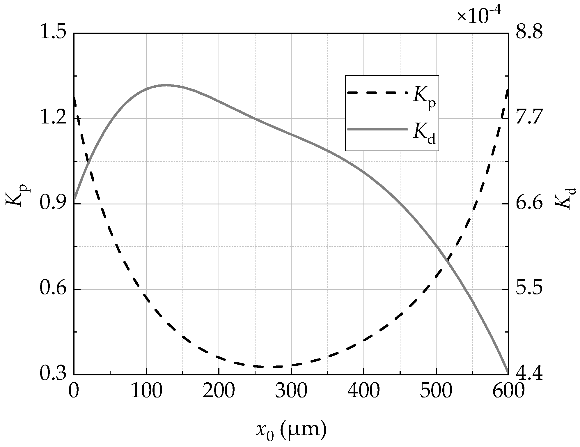
According to Formulas (15) and (16), the variation curve of Kp and Kd with the balanced position is shown in Figure 8.
As the balanced position deviates from the physical center, Kp increases rapidly. Kp increases approximately three times at a distance of around 300 μm from the physical center and increases approximately two times at approximately 200 μm. In general, the variation of the balanced position in the asymmetric AMB causes Kp to vary greater, whereas Kd displays more obvious asymmetric features.
Let us select a group of gain-scheduled PID controllers with different balanced positions of 50 μm, 100 μm, 200 μm, 300 μm, 400 μm, and 500 μm, and draw their Bode diagrams shown in Figure 9.
4. Simulation and Experiment
4.1. Simulation Result Analysis
Based on MATLAB/SIMULINK, a simulation model is established, as shown in Figure 10. The deviation between the rotor displacement observed by the sensor and the set value is transmitted to the controller. Through the amplifier, the control voltage is converted into the current signal within a suitable range.
In the simulation model, the user can freely set the balanced position of the rotor and independently select the controller as a parameter-fixed controller or a gain-scheduled controller. With the two different controllers, the simulation results of the step response are shown in Figure 11 and Figure 12, respectively.
The lowest end of the air gap of the auxiliary bearing is defined as the initial position. When the parameter-fixed controller in Table 3 is utilized, the rotor is stepped from the initial appointment to 50, 100, 200, 300, 400, and 500 μm, and the corresponding step response curves are shown in Figure 11.
It can be found from Figure 11 that the system with the parameter-fixed controller can only keep just a satisfactory performance in a specific narrow area. For example, the response performance is good when the balanced position is from 200 to 300 μm, whereas it is poor in other areas. When it is less than 100 μm or more than 400 μm, the overshoot has exceeded the limit of the auxiliary bearing (0–600 μm). If it is less than 50 μm or more than 500 μm, the system will be unstable because the controller cannot provide adequate stiffness and damping. These phenomena are consistent with the stiffness and damping variation curves shown in Figure 7.
In contrast, when the abovementioned gain-scheduled controllers are applied, the floating characteristic curves at different balanced positions are shown in Figure 12.
These figures imply that the rotor with the gain-scheduled controller can remain stable at any balanced position within the range of 50 to 500 μm. As the balanced position moves upward, the overshoot of the current response increases, whereas the steady-state value of the current gradually decreases. In practice, it is difficult to achieve equilibrium at 500 μm when considering the current and displacement response. Furthermore, the displacement overshoot at 400 μm exceeds the upper limit of the auxiliary bearing. In the range of 50 to 400 μm, the response performance is good and does not change significantly with the balanced position. The above range can be recommended for the actual commissioning.
4.2. Experiment Result Analysis
The main components of the experiment rig are shown in Figure 13. The thickness of the AMB shims and the auxiliary bearing was repeatedly adjusted, so that the physical centers of the two air gaps coincide. At the same time, the unilateral air gap between the thrust AMB and the auxiliary bearing is guaranteed to be 0.4 mm and 0.3 mm, respectively.
Formula (6) is discretized based on the bilinear transformation method, and then is written into the controller. The NI PXIe-8840 high-performance embedded product is employed as the control and monitoring system of the AMB. Its sampling frequency is 50 kHz, which can realize the real-time monitoring and control of the rotor state.
With the same gain-scheduled control strategy as the above simulation, the following step response characteristics of the rotor are obtained. Figure 14 is the step response with steps from 0 to 50, 100, 150, 250, and 350 μm, respectively. Figure 15 is the stair-like responses with a fixed step length of 50 μm. Experimental results demonstrate that the gain-scheduled control strategy proposed in this paper guarantees that the rotor remains stable in the range of 50 to 350 μm. When the rotor is balanced at 300 μm, the current of the upper and lower AMB is almost the same, and is equal to the bias current. Experimental phenomena match the previous design principle and verify the consistency between the actual and theoretical models at the design point.
It can be found from Figure 14 that, as the balanced position increases, the steady-state current decreases whereas the overshoot increases. When the balanced position is 50 μm, although the overshoot of the current response is the smallest, the stabilization time is the longest, and a lot of noise is introduced. The reason may be that the rotor is too far away from the upper AMB, which excites more prominent nonlinear characteristics of the electromagnetic force than those with a closer distance. When the rotor is balanced at 350 μm, both the response time and current overshoot are dramatic because of the large step size. It can be concluded that the equilibrium range is located below the physical center. In summary, the commissioning range of the compressor in actual operation is recommended to be in the field of 100 to 300 μm.
5. Conclusions
The paper studies the thrust AMB of the cold compressor, analyzes the change in the system stiffness and damping with the equilibrium position, and therefore proposes a gain-scheduled PID controller to cope with the variable equilibrium position. The research results show that, as the equilibrium position moves from the center to the magnetic poles on both sides, the system stiffness decreases whereas the damping increases. The asymmetry of the AMB exacerbates the unevenness of the variation. The control of the upper position is more complicated than that below the physical center because the upper AMB has a larger geometry. The simulation and experimental results indicate that gain-scheduled control ensures that the rotor remains stable in the range of 50 to 350 μm and possesses a breakneck response speed and slight overshoot in the field of 100 to 300 μm. This research has realized the automatic and real-time adjustment of the tip clearance of the cold compressor. The subsequent research will focus on the joint commissioning between the requirements of the superfluid helium system and the axial position of the magnetic suspension rotor.
Author Contributions
Conceptualization, S.Z. and J.W.; methodology, S.Z.; software, S.Z.; validation, S.Z. and J.W.; formal analysis, S.Z.; investigation, S.Z.; resources, J.W. data curation, S.Z.; writing—original draft preparation, S.Z.; writing—review and editing, S.Z. and J.W.; visualization, S.Z.; supervision, J.W.; project administration, J.W.; funding acquisition, S.Z. and J.W. All authors have read and agreed to the published version of the manuscript.
Funding
This research was funded by the fund of the State Key Laboratory of Technologies in Space Cryogenic Propellants, grant number SKLTSCPSKLTSCP202104.
Institutional Review Board Statement
Not applicable.
Informed Consent Statement
Not applicable.
Data Availability Statement
All of the data used in this paper can be obtained upon request to the corresponding author.
Conflicts of Interest
The authors declare no conflict of interest.
References
- Dong, X.B.; Wu, J.H.; Li, J.J.; Xu, X.D.; Su, H.; Shang, J.; Li, Q.; Gong, L.H. Impact of external heat transfer on the performance of a cold compressor used in superfluid helium system. Cryogenics 2020, 110, 103141. [Google Scholar] [CrossRef]
- Zhang, S.Y.; Pan, W.; Wei, C.B.; Wu, J.H. Structure design and simulation research of active magnetic bearing for helium centrifugal cold compressor. In Proceedings of the Materials Science and Engineering Conference, Madison, WI, USA, 9–13 July 2017; p. 268. [Google Scholar]
- Larsonneur, R. Principle of Active Magnetic Suspension. In Magnetic Bearings: Theory, Design, and Application to Rotating Machinery, 2nd ed.; Schweitzer, G., Maslen, E.H., Eds.; Springer: Berlin/Heidelberg, Germany, 2009; pp. 27–68. [Google Scholar]
- Liu, F.; Zhang, S.; Shang, J.; Wu, J. Influence of tip gap form on aerodynamic performance of cold compressor. Cryo. Supercond. 2021, 49, 49–57. [Google Scholar]
- Pesch, A.; Smirnow, A.; Pyrhonen, O.; Sawicki, J.T. Magnetic bearing spindle tool tracking through μ-synthesis robust control. IEEE/ASME Trans. Mech. 2015, 20, 1448–1457. [Google Scholar] [CrossRef]
- Yoon, S.Y.; Lin, Z.L.; Lim, K.T.; Goyne, C.; Allaire, P.E. Model Validation for an Active Magnetic Bearing Based Compressor Surge Control Test Rig. J. Vib. Acoust. 2010, 132, 71–81. [Google Scholar] [CrossRef]
- Chen, L.L.; Zhu, C.S.; Zhong, Z.X.; Wang, C.K.; Li, Z.N. Radial position control for magnetically suspended high-speed flywheel energy storage system with inverse system method and extended 2-DOF PID controller. IET Electr. Power Appl. 2019, 14, 71–81. [Google Scholar] [CrossRef]
- Smirnov, A.; Pesch, A.H.; Pyrhonen, O.; Sawicki, J.T. High-Precision Cutting Tool Tracking with a Magnetic Bearing Spindle. J. Dyn. Syst. Meas. Control 2015, 137, 051017. [Google Scholar] [CrossRef]
- Guan, X.; Zhou, J.; Wu, H.; Zhang, Y. Trajectory Tracking of Rotating Shaft with Active Magnetic Bearings under Different Reference Signals. Appl. Comput. Electron. 2019, 34, 1435–1444. [Google Scholar]
- Chen, S.Y.; Lin, F.J. Robust Nonsingular Terminal Sliding-Mode Control for Nonlinear Magnetic Bearing System. IEEE Trans. Contr. Syst. Technol. 2011, 19, 636–643. [Google Scholar] [CrossRef]
- Lin, F.J.; Chen, S.Y.; Huang, M.S. Adaptive complementary sliding-mode control for thrust active magnetic bearing system. Control Eng. Pract. 2011, 19, 711–722. [Google Scholar] [CrossRef]
- Han, B.C.; Cui, B.; Zheng, S.Q.; Zhang, Y.; Song, X.D. Model and experimental research on the relation between pressure and impeller clearance of magnetic levitation compressor. J. Vib. Meas. Diagn. 2019, 39, 286–291+441–442. [Google Scholar]
- Zhang, S.Y.; Liu, F.; Qin, H.L. Structure design and numerical simulation of axial active magnetic bearing with an asymmetric form. Cryo. Supercond. 2020, 48, 12–37+45. [Google Scholar]
- API 617 Axial and Centrifugal Compressors and Expander-Compressors for Petroleum, Chemical and Gas Industry Services; American Petroleum Institute API: Washington, DC, USA, 2002; pp. 180–184.
- ISO 14839-3 Mechanical Vibration—Vibration of Rotating Machinery Equipped with Active Magnetic Bearings—Part 3: Evaluation of Stability Margin; International Organization for Standardization ISO: London, UK, 2006; pp. 21–23.
Figure 1.
Sectional structure of magnetic suspension cold compressor.

Figure 2.
Structure diagram of thrust AMB model.

Figure 3.
ki and its percentage change with balanced position.

Figure 4.
kx and its percentage change with balanced position.

Figure 5.
The constant force generated by AMB varies with the balanced position.

Figure 6.
Sweep frequency test result of power amplifier.

Figure 7.
Variation curve of β and ξ with balanced position.

Figure 8.
Kp and Kd vary with balanced position.

Figure 9.
Bode plot of gain-scheduled PID controller.

Figure 10.
Simulation model based on SIMULINK.

Figure 11.
Step response simulation with parameter-fixed controller. (a) x0 = 50 μm; (b) x0 = 100 μm; (c) x0 = 200 μm; (d) x0 = 300 μm; (e) x0 = 400 μm; (f) x0 = 500 μm.
Figure 11.
Step response simulation with parameter-fixed controller. (a) x0 = 50 μm; (b) x0 = 100 μm; (c) x0 = 200 μm; (d) x0 = 300 μm; (e) x0 = 400 μm; (f) x0 = 500 μm.

Figure 12.
Step response simulation with gain-scheduled controller. (a) x0 = 50 μm; (b) x0 = 100 μm; (c) x0 = 200 μm; (d) x0 = 300 μm; (e) x0 = 400 μm; (f) x0 = 500 μm.
Figure 12.
Step response simulation with gain-scheduled controller. (a) x0 = 50 μm; (b) x0 = 100 μm; (c) x0 = 200 μm; (d) x0 = 300 μm; (e) x0 = 400 μm; (f) x0 = 500 μm.

Figure 13.
Photo of the cold compressor.

Figure 14.
Experiment of step response from 0. (a) x0 = 50 μm; (b) x0 = 100 μm; (c) x0 = 150 μm; (d) x0 = 250 μm; (e) x0 = 300 μm; (f) x0 = 350 μm.
Figure 14.
Experiment of step response from 0. (a) x0 = 50 μm; (b) x0 = 100 μm; (c) x0 = 150 μm; (d) x0 = 250 μm; (e) x0 = 300 μm; (f) x0 = 350 μm.

Figure 15.
Experiment of stair-like response with a fixed step size of 50 μm. (a) from x0 = 50 to 100 μm; (b) from x0 =100 to 150 μm; (c) from x0 = 150 to 200 μm; (d) from x0 = 200 to 250 μm; (e) from x0 = 250 to 300 μm; (f) from x0 = 300 to 350 μm.
Figure 15.
Experiment of stair-like response with a fixed step size of 50 μm. (a) from x0 = 50 to 100 μm; (b) from x0 =100 to 150 μm; (c) from x0 = 150 to 200 μm; (d) from x0 = 200 to 250 μm; (e) from x0 = 250 to 300 μm; (f) from x0 = 300 to 350 μm.


Table 1.
Parameters of thrust AMB.
| Name | Value |
|---|---|
| Bias current, i0 (A) | 0.85 |
| Unilateral air gap of the thrust AMB, xm (μm) | 400 |
| Unilateral air gap of the auxiliary bearing, xp (μm) | 300 |
| Upper AMB inner magnetic pole inner/outer diameter, a/b (mm) | 50/58.5 |
| Upper AMB outer magnetic pole inner/outer diameter, c/d (mm) | 74/80 |
| Lower AMB inner magnetic pole inner/outer diameter, e/f (mm) | 545/85 |
| Lower AMB outer magnetic pole inner/outer diameter, g/h (mm) | 76/80 |
| Number of coil turns of upper AMB, Nu | 225 |
| Number of coil turns of lower AMB, Nd | 175 |
| Structure parameter of upper AMB, ku | 15.062 |
| Structure parameter of lower AMB, kd | 13.662 |
Table 2.
Parameters of radial AMB and rotor.
| Name | Value |
|---|---|
| Bias current of radial AMB (A) | 1.1 |
| Air gap of radial AMB (μm) | 350 |
| Air gap of radial auxiliary bearing (μm) | 150 |
| Magnetic pole area of radial AMB (mm2) | 263 |
| Number of coil turns of radial AMB | 97 |
| Number of magnetic poles of radial AMB | 8 |
| Total length of rotor (mm) | 412 |
| Rotor mass, m (kg) | 6.2 |
| Diameter of middle part of rotor (mm) | 63 |
Table 3.
PID controller with fixed parameter.
| Name | Value |
|---|---|
| Proportional gain Kp0 | 0.32 |
| Integral gain Ki0 | 40 |
| Differential gain Kd0 | 7.5 × 10⁻⁴ |
| Differential time constant Td | 1/400π |
Publisher’s Note: MDPI stays neutral with regard to jurisdictional claims in published maps and institutional affiliations. |
© 2021 by the authors. Licensee MDPI, Basel, Switzerland. This article is an open access article distributed under the terms and conditions of the Creative Commons Attribution (CC BY) license (https://creativecommons.org/licenses/by/4.0/).
Share and Cite
MDPI and ACS Style
Zhang, S.; Wu, J. Gain-Scheduled Control of Asymmetric Thrust Magnetic Bearing. Actuators 2021, 10, 329. https://doi.org/10.3390/act10120329
AMA Style
Zhang S, Wu J. Gain-Scheduled Control of Asymmetric Thrust Magnetic Bearing. Actuators. 2021; 10(12):329. https://doi.org/10.3390/act10120329
Chicago/Turabian StyleZhang, Shuyue, and Jihao Wu. 2021. "Gain-Scheduled Control of Asymmetric Thrust Magnetic Bearing" Actuators 10, no. 12: 329. https://doi.org/10.3390/act10120329
Note that from the first issue of 2016, this journal uses article numbers instead of page numbers. See further details here.