Assessment Method for Combined Structural and Energy Retrofitting in Masonry Buildings


Abstract
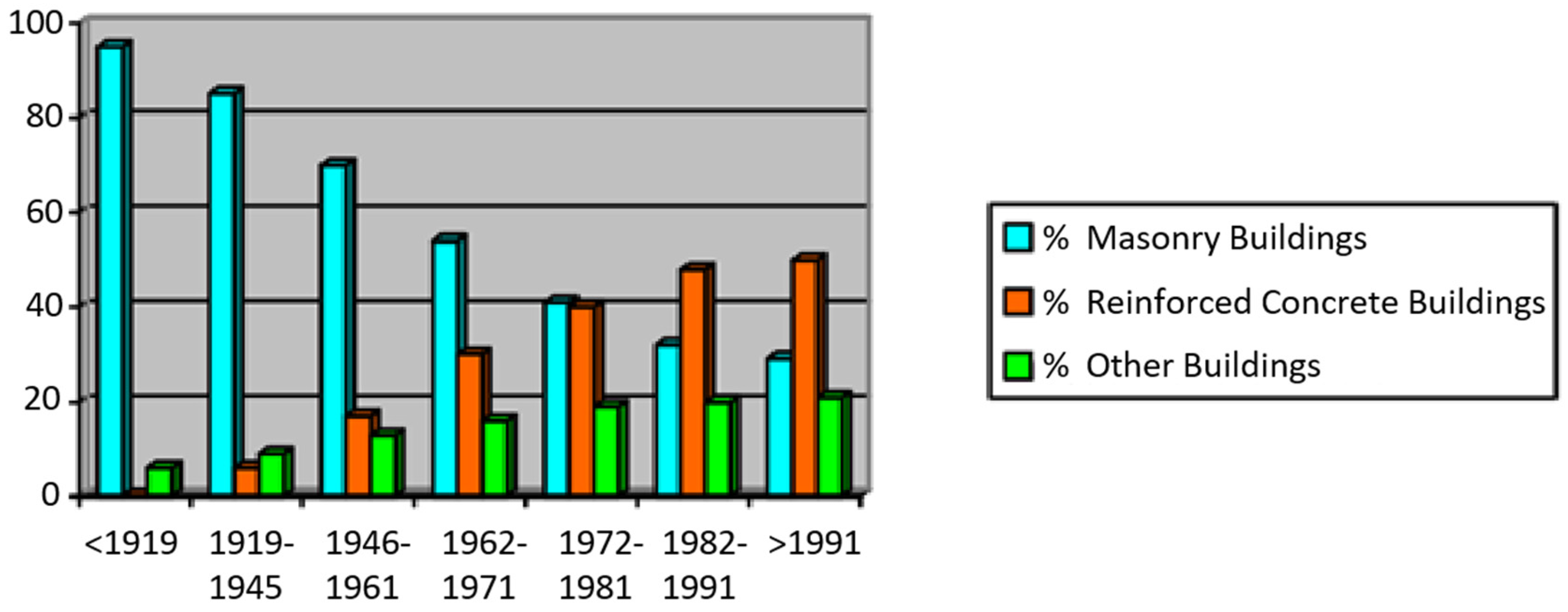
:1. Introduction
2. Retrofitting Techniques
2.1. Structural and Seismic Retrofitting
2.2. Energy Retrofitting
- -
- improvement of thermal performance of building façades,
- -
- optimization of building insulation,
- -
- modification of indoor temperature set-points,
- -
- improvement of the heating system efficiency,
- -
- installation of energy saving lighting and air ventilation control.
2.3. Combined Seismic and Energy Retrofitting
3. An Example of an Integrated Approach on Structural and Energy Features
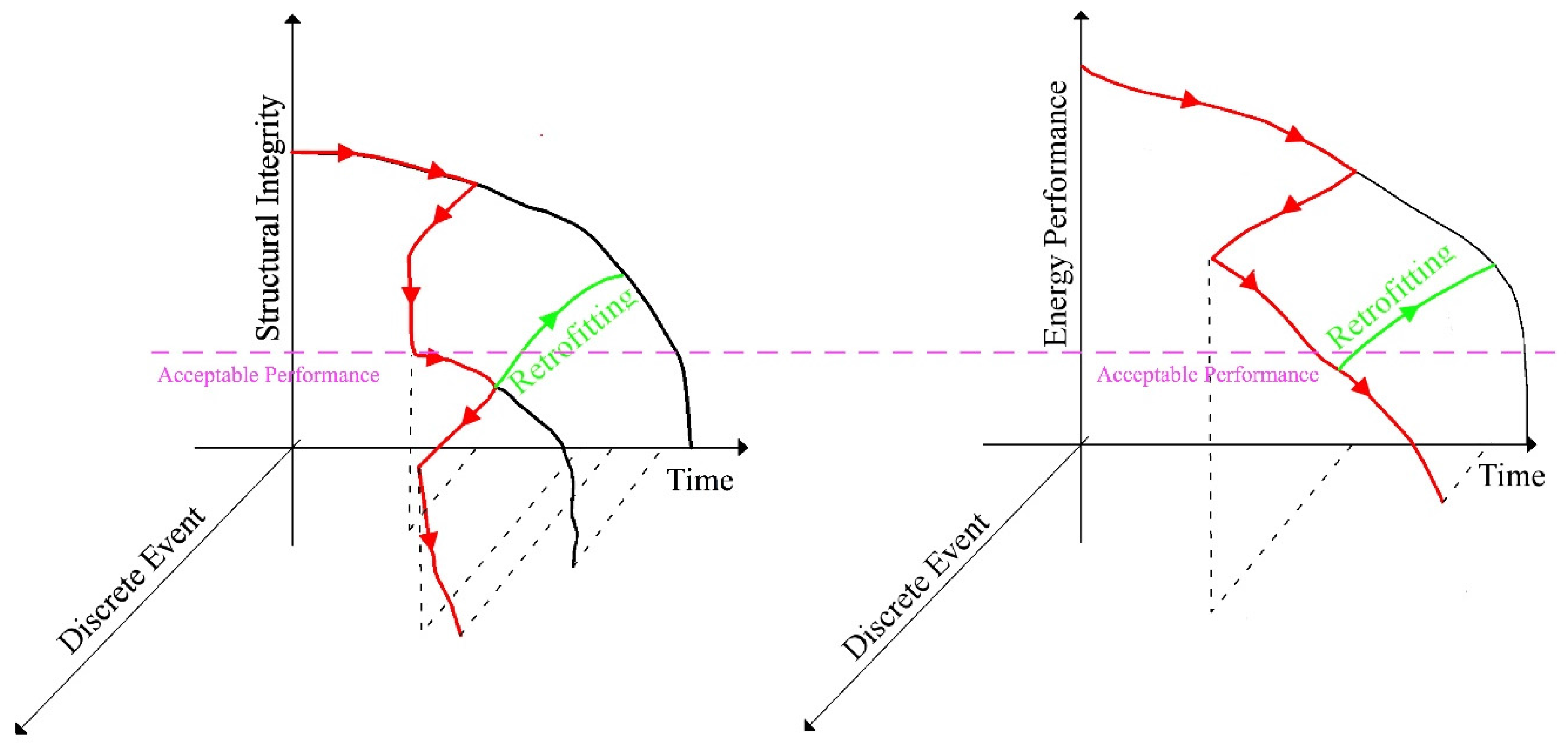
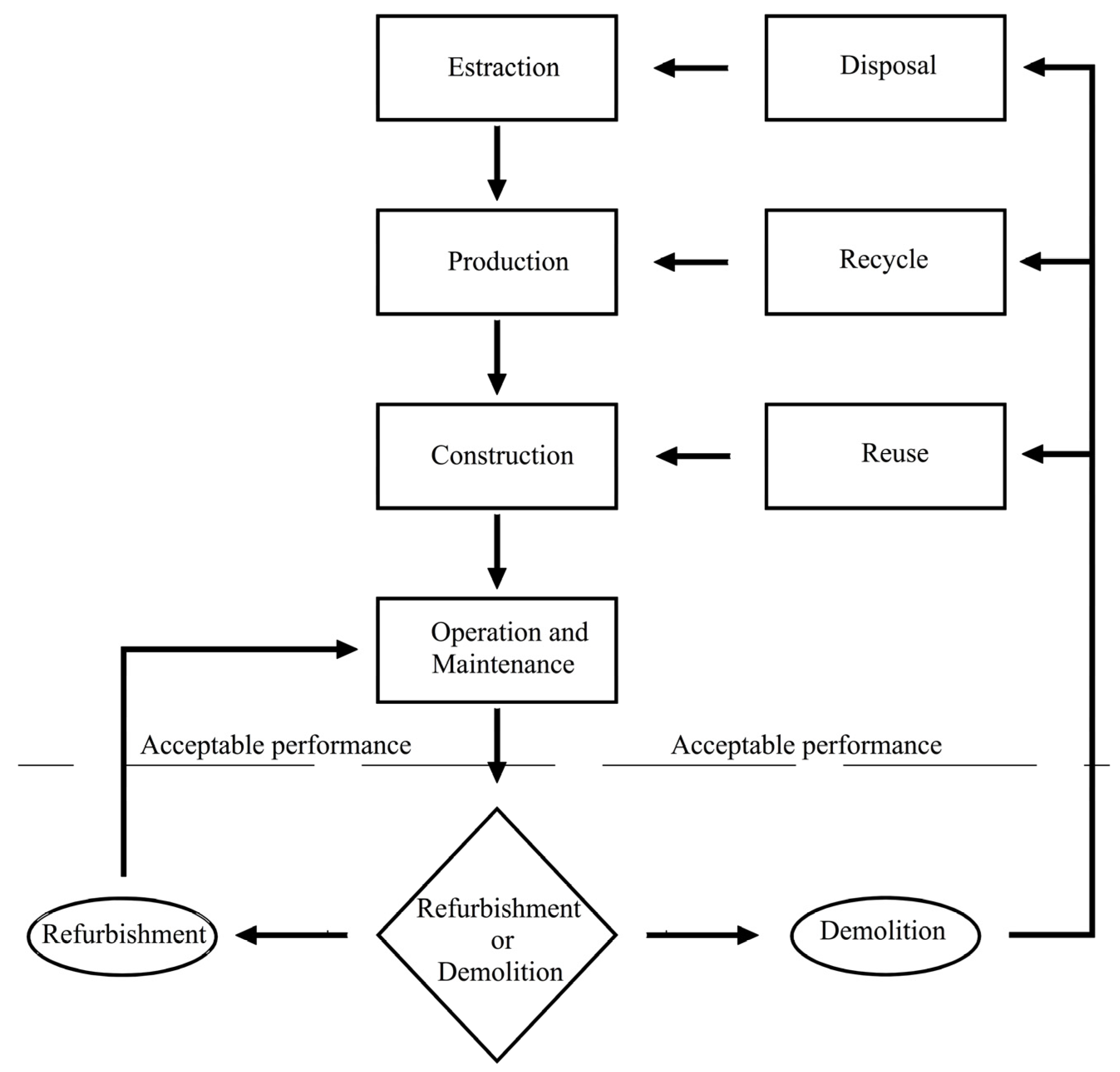
4. A Generalized Combined Approach of Structural and Energy Aspects
- investment cost
- maintenance cost
- environmental cost (i.e., consumption of CO2)
- social cost (i.e., rate of involved population).
5. Conclusions and Perspectives
Acknowledgments
Author Contributions
Conflicts of Interest
References
- Stochino, F.; Mistretta, F.; Meloni, P.; Carcangiu, G. Integrated approach for post-fire reinforced concrete structures assessment. Period. Polytech. Civ. 2017. [Google Scholar] [CrossRef]
- Acito, M.; Stochino, F.; Tattoni, S. Structural response and reliability analysis of RC beam subjected to explosive loading. AMM 2011, 82, 434–439. [Google Scholar] [CrossRef]
- Stochino, F. RC beams under blast load: Reliability and sensitivity analysis. Eng. Fail. Anal. 2016, 66, 544–565. [Google Scholar] [CrossRef]
- Giovino, G.; Olmati, P.; Garbati, S.; Bontempi, F. Blast resistance assessment of concrete wall panels: Experimental and numerical investigations. Int. J. Prot. Struct. 2014, 5, 349–366. [Google Scholar] [CrossRef]
- Sassu, M. The Reinforced Cut Wall (RCW): A Low-Cost Base Dissipator for Masonry Buildings. Earthq. Spectra 2016, 22, 533–554. [Google Scholar] [CrossRef]
- Sassu, M. Biaxiality effect on the energy dissipated by elastoplastic base-isolators. J. Eng. Mech. ASCE 2003, 22, 533–554. [Google Scholar] [CrossRef]
- Asteris, P.G.; Chronopoulos, M.P.; Chrysostomou, C.Z.; Varum, H.; Plevris, V.; Kyriakides, N.; Silva, V. Seismic vulnerability assessment of historical masonry structural systems. Eng. Struct. 2014, 62, 118–134. [Google Scholar] [CrossRef]
- Tesfamariam, S.; Sadiq, R.; Najjaran, H. Decision making under uncertainty—An example for seismic risk management. Risk Anal. 2010, 30, 78–94. [Google Scholar] [CrossRef] [PubMed]
- Calvi, G.M.; Sousa, L.; Ruggeri, C. Energy Efficiency and Seismic Resilience: A Common Approach. In Multi-Hazard Approaches to Civil Infrastructure Engineering; Gardoni, P., La Fave, J.M., Eds.; Springer International Publishing: Basel, Switzerland, 2016; pp. 165–208. [Google Scholar]
- El Gawady, M.; Lestuzzi, P.; Badoux, M. A review of conventional seismic retrofitting techniques for URM. In Proceedings of the 13th International Brick and Block Masonry Conference, Amsterdam, The Netherlands, 4–7 July 2004; pp. 1–10. [Google Scholar]
- Montes, P.; Fernandez, A. Behaviour of a hemispherical dome subjected to wind loading. J. Wind Eng. Ind. Aerodyn. 2001, 89, 911–924. [Google Scholar] [CrossRef]
- Jabarov, M.; Kozharinov, S.; Lunyov, A. Strengthening of damaged masonry by reinforced mortar layers. In Proceedings of the 7th WCEE, Istanbul, Turkey, 8–13 September 1980; Volume 6, pp. 73–80. [Google Scholar]
- Tomazevic, M. Earthquake-Resistant Design of Masonry Buildings; World Scientific: Singapore, 1999; Vol. 1. [Google Scholar]
- Karantoni, F.V.; Fardis, M.N. Effectiveness of seismic strengthening techniques for masonry buildings. J. Struct. Eng. ASCE 1992, 118, 1884–1902. [Google Scholar] [CrossRef]
- Kahn, L. Shotcrete retrofit for unreinforced brick masonry. In Proceedings of the 8th WCEE, San Francisco, CA, USA, 21–28 July 1984; pp. 583–590. [Google Scholar]
- Prota, A.; Marcari, G.; Fabbrocino, G.; Manfredi, G.; Aldea, C. Experimental in plane behaviour of tuff masonry strengthened with cementitious matrix-grid composites. J. Compos. Constr. 2006, 10, 223–233. [Google Scholar] [CrossRef]
- Papanicolaou, C.G.; Triantafillou, T.C.; Karlos, K.; Papathanasiou, M. Textile reinforced mortar (TRM) versus FRP as strengthening material of URM walls: In-Plane cyclic loading. Mater. Struct. 2007, 40, 1081–1097. [Google Scholar] [CrossRef]
- Papanicolaou, C.G.; Triantafillou, T.C.; Papathanasiou, M.; Karlos, K. Textile reinforced mortar (TRM) versus FRP as strengthening material of URM walls: Out-of-Plane cyclic loading. Mater Struct. 2008, 41, 143–157. [Google Scholar] [CrossRef]
- Parisi, F.; Lignola, G.P.; Augenti, N.; Prota, A.; Manfredi, G. Nonlinear behaviour of a masonry subassemblage before and after strengthening with inorganic matrix-grid composites. J. Compos. Constr. 2011, 15, 821–832. [Google Scholar] [CrossRef]
- Babaeidarabad, S.; De Caso, F.; Nanni, A. Out-of-plane behavior of URM walls strengthened with fabric-reinforced cementitious matrix composite. J. Compos. Constr. 2014, 18, 04013057. [Google Scholar] [CrossRef]
- Calvi, G.; Magenes, G. Experimental results on unreinforced masonry shear walls damaged and repaired. In Proceedings of the 10th IB2MaC, Calgary, AB, Canada, 5–7 July 1994; pp. 509–518. [Google Scholar]
- Schuller, M.; Atkinson, R.; Borgsmiller, J. Injection grouting for repair and retrofit of unreinforced masonry. In Proceedings of the 10th IB2MaC, Calgary, AB, Canada, 5–7 July 1994; pp. 549–558B. [Google Scholar]
- Papanicolaou, C.; Triantafillou, T.; Lekka, M. Externally bonded grids as strengthening and seismic retrofitting materials of masonry panels. Constr. Build Mater. 2011, 25, 504–514. [Google Scholar] [CrossRef]
- Borri, A.; Corradi, M.; Speranzini, E.; Giannantoni, A. Consolidation and Reinforcing of stone wall using a reinforced repointing grid. In Proceedings of the 6th International Conference of Structural Analysis of Historical Construction, Bath, UK, 2–4 July 2008. [Google Scholar]
- Giresini, L.; Sassu, M. Horizontally restrained rocking blocks: Evaluation of the role of boundary conditions with static and dynamic approaches. Bull. Earthq. Eng. 2017, 15, 385–410. [Google Scholar] [CrossRef]
- Giresini, L.; Fragiacomo, M.; Sassu, M. Rocking analysis of masonry walls interacting with roofs. Eng. Struct. 2016, 116, 107–120. [Google Scholar] [CrossRef]
- Yu, Z.; Zhengyun, W.; Weiping, Z. Experimental research on aseismic strengthening of block masonry buildings using thin structural columns. In Proceedings of the 11th IB2MaC, Shanghai, China, 14–16 October 1997; pp. 626–633. [Google Scholar]
- Chuxian, S.; Guiqiu, L.; Wenchao, W. The design of Brick masonry structure with concrete column. In Proceedings of the 11th IB2MaC, Shanghai, China, 14–16 October 1997; pp. 626–633. [Google Scholar]
- Lissel, S.; Shrive, N. Construction of diaphragm walls post-tensioned with carbon fiber reinforced polymer tendons. In Proceedings of the 9th NAMC, Clemson, SC, USA, 9 June 2003; pp. 192–203. [Google Scholar]
- Rosenboom, O.; Kowalsky, M. Investigation of alternative details for seismic design of post-tensioned clay masonry walls. In Proceedings of the 9th NAMC, Clemson, SC, USA, 9 June 2003; pp. 475–485. [Google Scholar]
- Casapulla, C.; Cascini, L.; Portioli, F.; Landolfo, R. 3D macro and micro-block models for limit analysis of out-of-plane loaded masonry walls with non-associative Coulomb friction. Meccanica 2014, 49, 1653–1678. [Google Scholar] [CrossRef]
- Casapulla, C.; Jossa, P.; Maione, A. Rocking motion of a masonry rigid block under seismic actions: A new strategy based on the progressive correction of the resonance response. Ing. Sismica 2010, 27, 35–48. [Google Scholar]
- Ehsani, M.R.; Saadatmanesh, H.; Al-Saidy, A. Shear behavior of URM retrofitted with FRP overlays. J. Compos. Constr. 1997, 1, 17–25. [Google Scholar] [CrossRef]
- Albert, M.L.; Elwi, A.E.; Cheng, J.R. Strengthening of unreinforced masonry walls using FRPs. J. Compos. Constr. 2001, 5, 76–84. [Google Scholar] [CrossRef]
- Gattesco, N.; Boem, I.; Dudine, A. Diagonal compression tests on masonry walls strengthened with a GFRP mesh reinforced mortar coating. Bull. Earthq. Eng. 2015, 13, 1703–1726. [Google Scholar] [CrossRef]
- Priestley, M.J.N.; Seible, F. Design of seismic retrofit measures for concrete and masonry structures. Constr. Build. Mater. 1995, 9, 365–377. [Google Scholar] [CrossRef]
- Buchan, P.A.; Chen, J.F. Blast resistance of FRP composites and polymer strengthened concrete and masonry structures—A state-of-the-art review. Compos. Eng. Part B 2007, 38, 509–522. [Google Scholar] [CrossRef]
- Davidson, J.S.; Porter, J.R.; Dinan, R.J.; Hammons, M.I.; Connell, J.D. Explosive testing of polymer retrofit masonry walls. J. Perform. Constr. Facil. 2004, 18, 100–106. [Google Scholar] [CrossRef]
- Marques, R.; Lamego, P.; Lourenco, P.B.; Sousa, M.L. Efficiency and cost-benefit analysis of seismic strengthening techniques for old residential buildings in Lisbon. J. Earthq. Eng. 2017, 1–36. [Google Scholar] [CrossRef]
- Calvi, G.M. Choices and criteria for seismic strengthening. J. Earthq. Eng. 2013, 17, 769–802. [Google Scholar] [CrossRef]
- Ma, Z.; Cooper, P.; Daly, D.; Ledo, L. Existing building retrofits: Methodology and state-of-the-art. Energy Build. 2012, 55, 889–902. [Google Scholar] [CrossRef]
- Ascione, F.; De Rossi, F.; Vanoli, G.P. Energy retrofit of historical buildings: Theoretical and experimental investigations for the modelling of reliable performance scenarios. Energy Build. 2011, 43, 1925–1936. [Google Scholar] [CrossRef]
- Seddiki, M.; Anouche, K.; Bennadji, A.; Boateng, P. A multi-criteria group decision-making method for the thermal renovation of masonry buildings: The case of Algeria. Energy Build. 2016, 129, 471–483. [Google Scholar] [CrossRef]
- Cole, R.J. Energy and greenhouse gas emissions associated with the construction of alternative structural systems. Build. Environ. 1998, 34, 335–348. [Google Scholar] [CrossRef]
- Al-Homoud, M.S. Performance characteristics and practical applications of common building thermal insulation materials. Build. Environ. 2005, 40, 353–366. [Google Scholar] [CrossRef]
- Jelle, B.P. Traditional, state-of-the-art and future thermal building insulation materials and solutions—Properties, requirements and possibilities. Energy Build. 2011, 43, 2549–2563. [Google Scholar] [CrossRef]
- Al-Jabri, K.S.; Hago, A.W.; Al-Nuaimi, A.S.; Al-Saidy, A.H. Concrete blocks for thermal insulation in hot climate. Cem. Concr. Res. 2005, 35, 1472–1479. [Google Scholar] [CrossRef]
- Leitão, D.; Barbosa, J.; Soares, E.; Miranda, T.; Cristelo, N.; Briga-Sá, A. Thermal performance assessment of masonry made of ICEB’s stabilised with alkali-activated fly ash. Energy Build. 2017, 139, 44–52. [Google Scholar] [CrossRef]
- Mac Mullen, J.; Zhang, Z.; Radulovic, J.; Herodotou, C.; Totomis, M.; Dhakal, H.N.; Bennett, N. Titanium dioxide and zinc oxide nano-particulate enhanced oil-in-water (O/W) facade emulsions for improved masonry thermal insulation and protection. Energy Build. 2012, 52, 86–92. [Google Scholar] [CrossRef]
- Zhang, Z.; Mac Mullen, J.; Dhakal, H.N.; Radulovic, J.; Herodotou, C.; Totomis, M.; Bennett, N. Enhanced water repellence and thermal insulation of masonry by zinc oxide treatment. Energy Build. 2012, 54, 40–46. [Google Scholar] [CrossRef]
- Sassu, M.; Giresini, L.; Bonannini, E.; Puppio, M.L. On the Use of Vibro-Compressed Units with Bio-Natural Aggregate. Buildings 2016, 6, 40. [Google Scholar] [CrossRef]
- Dzyuzer, V.Y.; Shvydkii, V.S. Thermal Insulation of the Refractory Masonry in Glassmaking Furnaces. Glass Ceram. 2015, 71, 365–368. [Google Scholar] [CrossRef]
- Stefanidou, M.; Karozou, A. Testing the effectiveness of protective coatings on traditional bricks. Constr. Build. Mater. 2016, 111, 482–487. [Google Scholar] [CrossRef]
- Mata, E.; Sasic Kalagasidis, A.; Johnsson, F. Cost-effective retrofitting of Swedish residential buildings: Effects of energy price developments and discount rates. Energy Effic. 2015, 8, 223–237. [Google Scholar] [CrossRef]
- Tronchin, L.; Tommasino, M.C.; Fabberi, K. On the cost-optimal levels of energy-performance requirements for buildings: A case study with economic evaluation in Italy. Int. J. Sustain. Energy Plan. Manag. 2014, 3, 49–62. [Google Scholar]
- Bonakdar, F.; Kalagasidis, A.S.; Mahapatra, K. The Implications of Climate Zones on the Cost-Optimal Level and Cost-Effectiveness of Building Envelope Energy Renovation and Space Heat Demand Reduction. Buildings 2017, 7, 39. [Google Scholar] [CrossRef]
- Triantafillou, T.C.; Karlos, K.; Kefalou, K.; Argyropoulou, E. An innovative structural and energy retrofitting system for URM walls using textile reinforced mortars combined with thermal insulation: Mechanical and fire behavior. Constr. Build. Mater. 2017, 133, 1–13. [Google Scholar] [CrossRef]
- Giresini, L. Energy-based method for identifying vulnerable macro-elements in historic masonry churches. Bull. Earthq. Eng. 2016, 14, 919–942. [Google Scholar] [CrossRef]
- Lamego, P.; Lourenço, P.B.; Sousa, M.L.; Marques, R. Seismic vulnerability and risk analysis of the old building stock at urban scale: Application to a neighbourhood in Lisbon. Bull. Earthq. Eng. 2017, 15, 2901–2937. [Google Scholar] [CrossRef]
- Federal Emergency Management Agency. Prestandard and Commentary for the Seismic Rehabilitation of Buildings (FEMA Publication No. 356); the American Society of Civil Engineers for the Federal Emergency Management Agency: Washington, DC, USA, 2000.
- Structural Engineers Association of California. Vision 2000—A Framework for Performance-Based Engineering; Structural Engineers Association of California: Sacramento, CA, USA, 1995. [Google Scholar]
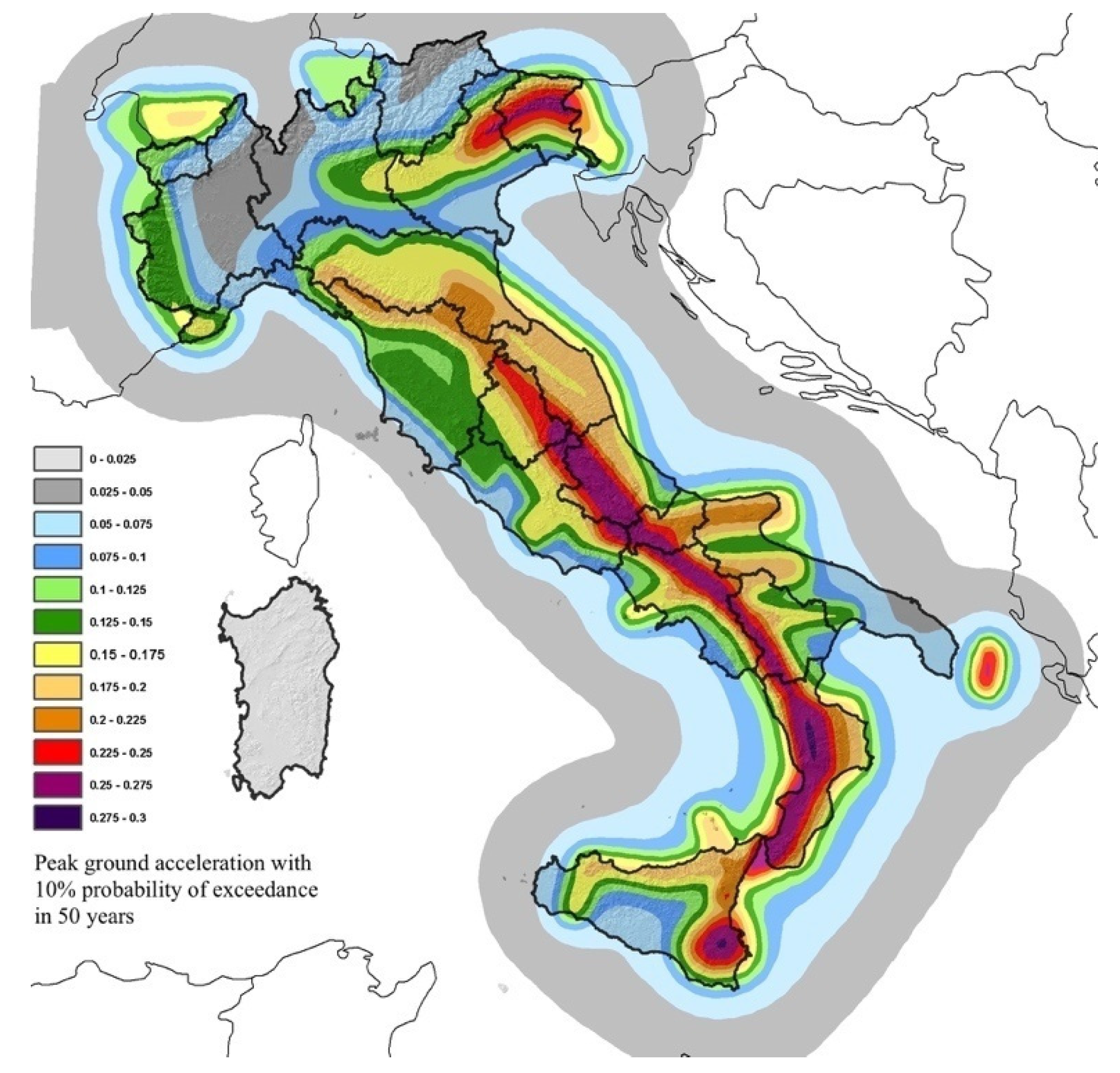
- Italian Institute of Geophysics and Volcanology: Map of seismic hazard. Available online: https.www.ingv.it (accessed on 1 June 2017).
- Italian Technical Norm on Energy Regulations. Available online: http://www.gazzettaufficiale.it/eli/id/1993/10/14/093G0451/sg (accessed on 1 June 2017).
- Circ.2009-Instructions for “Technical Norms for Constructions”. Available online: http://cslp.mit.gov.it/index.php?option=com_content&task=view&id=79&Itemid=20 (accessed on 1 June 2017).


© 2017 by the authors. Licensee MDPI, Basel, Switzerland. This article is an open access article distributed under the terms and conditions of the Creative Commons Attribution (CC BY) license (http://creativecommons.org/licenses/by/4.0/).
Share and Cite
Sassu, M.; Stochino, F.; Mistretta, F. Assessment Method for Combined Structural and Energy Retrofitting in Masonry Buildings. Buildings 2017, 7, 71. https://doi.org/10.3390/buildings7030071
Sassu M, Stochino F, Mistretta F. Assessment Method for Combined Structural and Energy Retrofitting in Masonry Buildings. Buildings. 2017; 7(3):71. https://doi.org/10.3390/buildings7030071
Chicago/Turabian StyleSassu, Mauro, Flavio Stochino, and Fausto Mistretta. 2017. "Assessment Method for Combined Structural and Energy Retrofitting in Masonry Buildings" Buildings 7, no. 3: 71. https://doi.org/10.3390/buildings7030071