Article

Environmental Microvibration Analysis Method for Vibration Isolation Research in High-Precision Laboratories

1
School of Ocean and Civil Engineering, Shanghai Jiao Tong University, 800 Dongchuan Road, Minhang District, Shanghai 200240, China
2
School of Electronic Information and Electrical Engineering, Shanghai Jiao Tong University, Shanghai 200240, China
3
China Aviation Planning and Design Institute (Group) Co., Ltd., Beijing 100120, China
*
Author to whom correspondence should be addressed.
Buildings 2024, 14(5), 1215; https://doi.org/10.3390/buildings14051215
Submission received: 21 March 2024 / Revised: 9 April 2024 / Accepted: 20 April 2024 / Published: 24 April 2024

Abstract

:
Environmental microvibrations, often originating from unidentified sources, pose a significant challenge for predicting and controlling their complex wave fields, potentially leading to measurement errors of sensitive instruments in high-precision laboratories and impacting the accuracy of experimental outcomes. Therefore, investigating effective control measures for environmental microvibrations under passive conditions is key to addressing such engineering issues. This paper presents a finite element analysis method tailored to address environmental microvibrations in the absence of apparent sources. This method involves obtaining the vibration time history at specific ground surface points through field measurements and combining the Rayleigh wave velocity attenuation character with depth at the center frequencies of one-third octave bands within the 1–100 Hz frequency range; the vibration time history at any depth in the soil is calculated. These calculated vibrations are then applied as input loads to the corresponding nodes on one boundary of the foundation–soil model, serving as the source of environmental microvibrations. The predicted results are compared with measured data and the empirical point source input method, indicating that this approach is more precise and efficient, providing valuable reference for the prediction and analysis of environmental microvibrations. In addition, utilizing this method, the study examines the effects of pile foundation parameters such as the pile length, burial depth, and concrete baseplate thickness on the vibration isolation performance of environmental microvibrations, providing guidance for designing pile foundation isolation.

1. Introduction

Modern high-precision laboratories serve as pivotal facilities for researchers conducting delicate experiments and measurements and play an instrumental role in fostering technological innovation and addressing intricate scientific quandaries [1,2]. Compared to conventional buildings, these laboratories exhibit significant distinctions in design and functionality, particularly with their internal configuration of costly and highly sophisticated instrumentation [3]. Given the high sensitivity of these instruments to environmental microvibrations [4], stringent vibration control requirements are imposed on laboratories, often demanding that vibration amplitudes be maintained within the microscale range [5]. Additionally, constrained by urban land resources, high-precision laboratories are frequently located in high-tech parks adjacent to major traffic arteries, inevitably exposing them to environmental microvibrations [6,7]. Therefore, effective prediction and assessment of environmental microvibrations are crucial for ensuring the normal operation of these laboratories [8,9].
In the field of environmental microvibrations induced by traffic loads, extensive research has been conducted on systems such as high-speed railways, ground transportation, and subways. For example, Xia et al. [10] devised a comprehensive dynamic model encompassing train–track–ground interactions to explore the ground vibrations caused by train movements. Mhanna et al. [11] utilized a global numerical model to predict ground vibrations induced by traffic, facilitating a realistic simulation of road traffic loads and their impact on ground vibrations. Huang et al. [12] investigated the propagation of vibrations in ground soil and the effects of soil-structure interactions on vibrations of buildings adjacent to curved subway sections. Most existing studies focus on scenarios with identifiable vibration sources. However, the origins of environmental microvibrations are often elusive, and during propagation, these vibrations can undergo processes of superposition, reflection, and refraction, leading to complex wave fields [13,14]. Hence, traditional methods for identifying vibration source inputs are inadequate. Instead, it is crucial to consider the application of equivalent vibration fields around the structures to examine the structural responses to environmental microvibrations [15].
The establishment of an equivalent vibration field necessitates consideration of the propagation and attenuation patterns of vibrations in soil layers. Lysmer et al. [16] and Woods [17] theoretically proposed attenuation curves for horizontal and vertical vibration displacements with depth in an elastic half-space. Huang et al. [18] employed the matrix transfer method to investigate the depth attenuation curves of Rayleigh waves in layered foundations. Building upon this, Yu et al. [19] conducted a comprehensive study of train-induced vibration attenuation with depth through field experiments, numerical simulations, and theoretical analysis. Ren et al. [20] proposed a layered uniform medium attenuation model incorporating material and geometric damping parameters based on the Bornitz equation. In terms of numerical simulation, Picoux and Houedec [21] proposed a semi-analytical ground vibration attenuation model for peaty soil sites, validated against empirical data. Tang et al. [22] examined the variations in near-field vibrations with depth and the impact of train speed through field testing and finite element simulation. However, the application of these vibration propagation and attenuation methods for predicting and analyzing microvibrations under passive environmental conditions remains relatively limited in existing research.
To effectively control the impact of environmental microvibrations on human bodies and buildings, research efforts can be initiated from the perspectives of the vibration source, propagation path, and the objects experiencing the vibrations, aiming to explore efficient damping and isolation techniques. Woods et al. [23] derived a set of isolation principles through experimental studies, revealing that when the diameter of a pile array exceeds one-sixth of the wavelength, a relatively ideal isolation effect can be achieved. In addressing the issue of subway vibrations in Beijing, Gupta et al. [24] identified the use of floating slab tracks as an effective vibration damping measure. Kuznetsov [25] constructed seismic barriers to effectively block the transmission of seismic waves to protected areas. For Very Large Floating Structures (VLFSs), which are more frequently impacted by ocean waves than terrestrial buildings, Chanda et al. [26] systematically analyzed various configurations of partially porous barriers. They discovered that optimizing the design and arrangement of these barriers significantly reduces wave impacts on VLFSs. Beyond these isolation methods, enhancing the inherent vibration isolation capabilities of structures is equally important and warrants further attention.
In the study of vibration isolation in buildings, utilizing the foundation structures of buildings for isolation is a critical aspect, necessitating thorough consideration of soil-structure interactions to further optimize the foundation isolation design. Rojas et al. [27] proposed a nonlinear Lagrangian model that accounts for the dynamic interaction between soil and multilayer planar frames, offering commendable accuracy in scenarios of large structural deformations. Zou et al. [28] discussed the impact of soil stiffness on building vibrations, asserting that soil stiffness plays a significant role in the transmission of vibrations from the soil to the building structure. Lopez et al. [29] and Sadeghi et al. [30], drawing on real-world engineering projects, developed models to study the factors influencing the vibration response of building floors, focusing on mechanical parameters of building structures and soil-structure interactions.
Therefore, based on the existing theories of vibration attenuation with depth in soil, this paper proposes a numerical analysis method tailored to passive vibration characteristics for the prediction and control of structural responses induced by environmental microvibrations. The validity of this method is confirmed through a comparative analysis of numerical simulation results and on-site measurements. Finally, this method is employed to analyze the isolation effects of pile length, burial depth, and baseplate thickness on pile foundations.

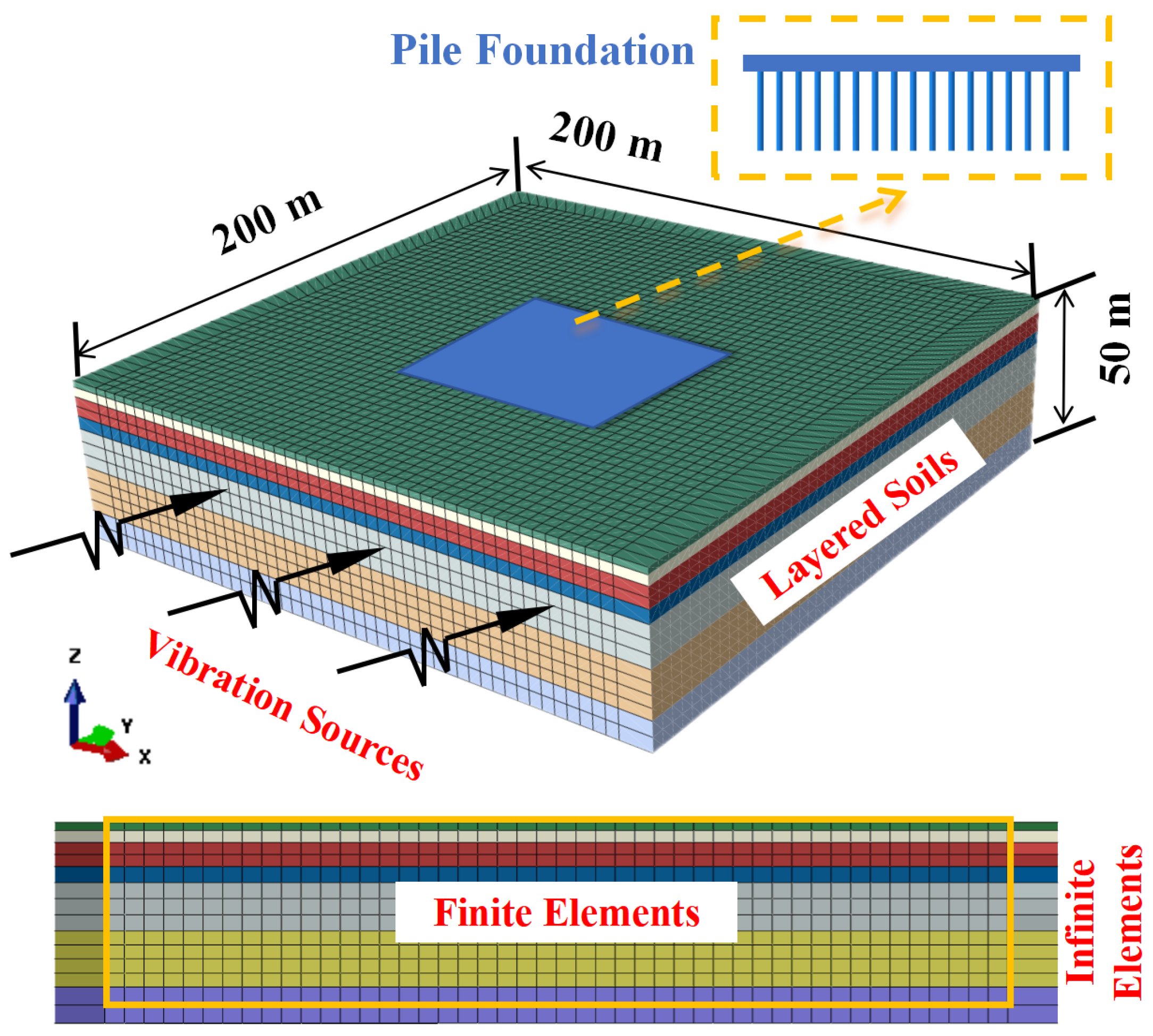
2. Finite–Infinite Foundation–Soil Model

A three-dimensional finite element method (FEM) using ABAQUS 6.14 is employed to simulate the impact of field environmental microvibrations on the surface vibration response of foundation structures. As depicted in Figure 1, the established finite element model consists of two types of media: pile foundation and soil. The overall dimensions of the model are 200 m × 200 m × 50 m, with the foundation located in the middle area of the model’s surface, measuring 50 m × 50 m, aimed at investigating the vibration isolation effects of pile foundations under different conditions. The piles and pile caps are made of reinforced concrete with an elastic modulus of 30 GPa; circular cross-sections are chosen for the piles, modeled using line elements, while specific component parameters under different working conditions are detailed in the corresponding analysis sections. The dynamic characteristics of the foundation and soil are considered highly coupled. Therefore, treating pile–soil interactions as embedded zone constraints can effectively describe the contact behavior between the piles and soil. The soil and pile foundation are modeled using structured grid partitioning with C3D8 finite elements, with the bottom boundary of the foundation soil model fully fixed [31]. In dynamic analysis of infinitely large media such as foundations, a primary concern with artificial truncation boundaries is the reflection of waves at the interface of these boundaries, causing energy to be reflected back into the analysis domain instead of propagating to infinity. Therefore, CIN3D8 infinite element boundaries with sweeping grid division are employed at the three boundaries around the model and at the bottom boundary to effectively absorb vibration energy and prevent reflection errors in wave propagation [32,33]. To simulate the magnitude of environmental microvibrations around a high-precision laboratory under real-world conditions, the vibration input load is applied only at all nodes along one lateral boundary of the model, with the lateral boundary measuring 100 m × 50 m. This boundary is located at a horizontal distance of 75 m from the pile foundation.
This high-precision laboratory initiative, located in a soft soil area of Shanghai, features a multi-layered soil foundation, as per onsite borehole analysis. The stratum, comprising seven distinct soil types in descending order, includes back fill, silty clay, sandy clay, sandy silt-like cohesive soil, silty clay, clay, and silty clay, with their specific parameters detailed in Table 1. Owing to the minimal displacements within the soil structure prompted by environmental microvibrations and their insubstantial impact, the soil skeleton is capable of elastic recovery from such deformations. In this process, the plastic deformation of the soil can be neglected, assuming that the soil undergoes ideal elastic deformation. Therefore, different soil layers were modeled as linear elastic models [34,35], with the pile foundation structure adopting a linear elastic framework. Moreover, the model assumes negligible material damping, which is generally considered to have a minor effect on environmental vibrations and poses challenges in precise quantification [19,36].
The Dynamics/Explicit procedure with the central difference method, which is usually used for short-time dynamic problems, was used to solve the dynamic response of the model, with a total calculation time of 20 s and a fixed time step of 0.001 s. To ensure the accuracy of the simulation, the element size should be smaller than 1/10 of the minimum shear wavelength [37,38]. Five types of mesh dimensions are set at 1 m, 1.5 m, 2 m, 2.5 m, and 3 m for mesh size analysis. Refining the grid to 2 m weakens the impact of further refinement on the results, as further grid refinement would significantly reduce computational efficiency. Therefore, the element size for the entire model is set to 2 m, with the mesh element edge length in the core area (where the pile foundation is arranged) set to 1 m, to maintain sufficient accuracy in the frequency response, which is less than one-tenth of the minimum shear wavelength of the soil. Given the soil shear wave speed of approximately 174 m/s and the site-measured fundamental frequency of 2 Hz, the element size of the soil is set to 2 m, which is also less than one-tenth of the minimum shear wavelength of the soil, while the element size of the pile foundation structure is set to be 0.5–1 m. In this simulation, there are 224,497 elements and 238,464 nodes in total.

3. Vibration Input Load along Depth

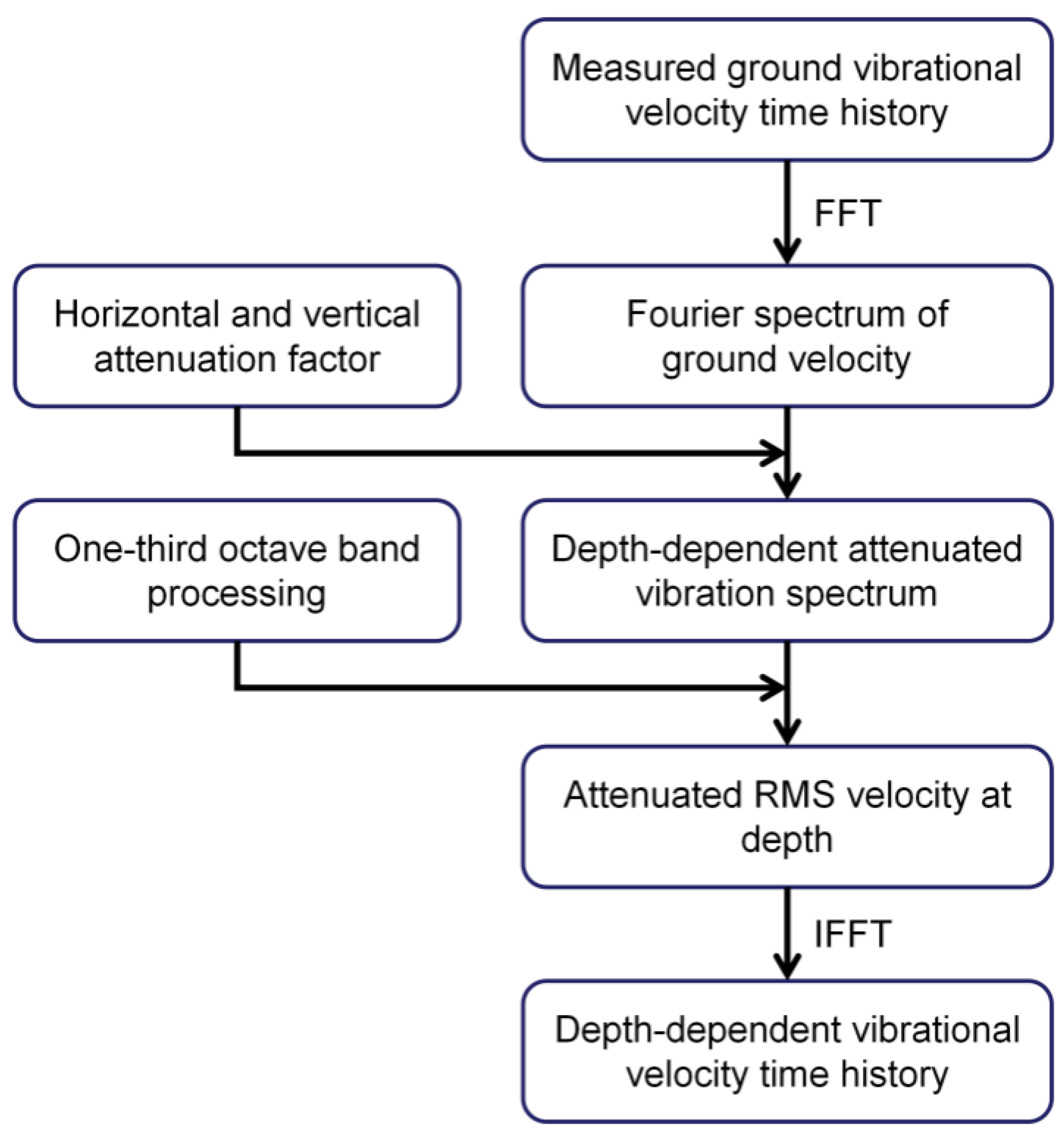
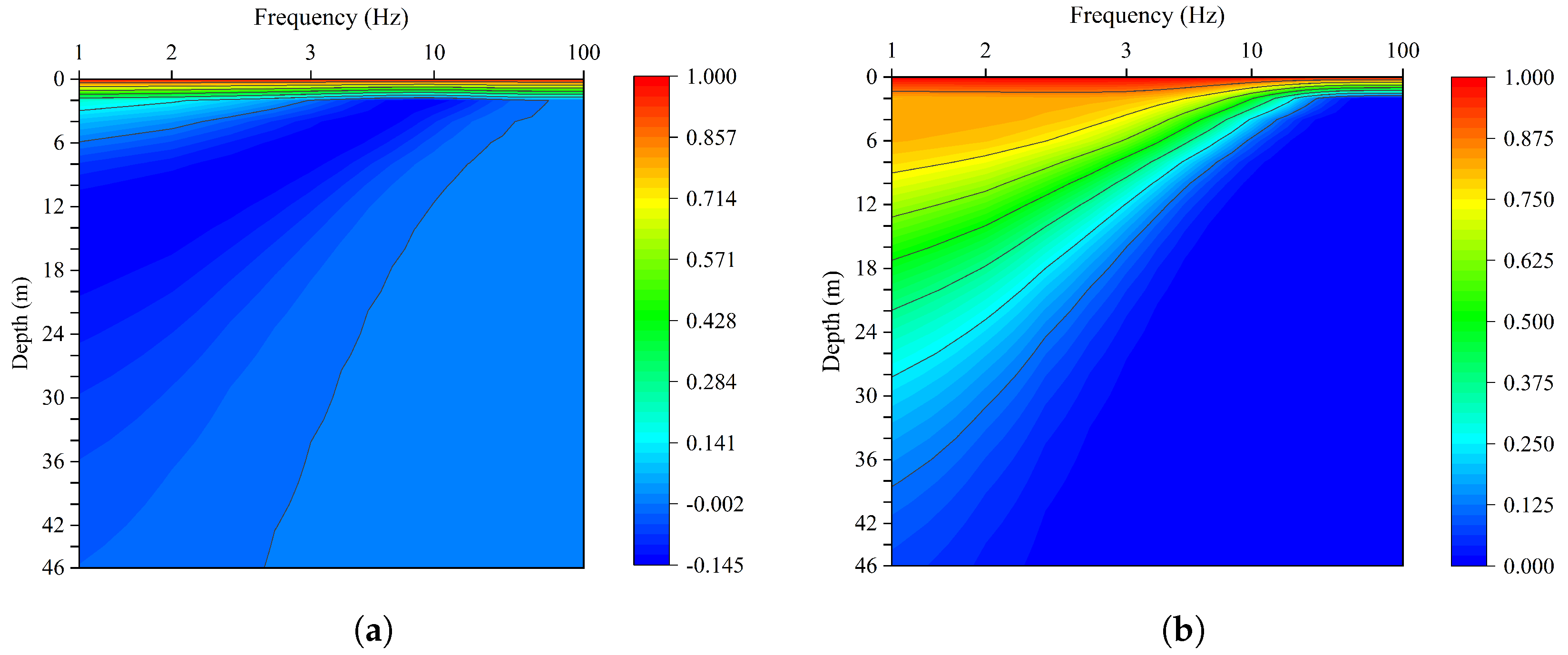
3.1. Vibration Attenuation Model along Depth

It is well known that elastic layered media exhibit various forms of waves under vibration [39]. However, from an energy perspective, Rayleigh waves dominate in the far field, which can be considered at distances of 3–4 times the Rayleigh wavelength from the source [40]. Moreover, their attenuation rate with increasing distance is slower compared to other waves. Due to the uncertain and distant locations of the sources of ambient microvibrations, in this paper, it can be reasonably inferred that measurement points P1–P5 are situated in the far field, where Rayleigh waves prevail, making the Rayleigh wave attenuation characteristics with depth the most noteworthy.
To address the technical challenges and economic costs associated with the in situ measurement of subsurface vibrations, this study introduces an elastic theory-based model aimed at accurately estimating the attenuated velocity of Rayleigh waves at a certain depth based on the surface measurements. The computational workflow is illustrated in Figure 2.
The initial step involves calculating the attenuated Fourier spectrum of Rayleigh waves at various frequencies and particular depths by employing the attenuation factor from the elastic semi-space method [17,41]. Subsequently, the second step involves one-third octave band processing, utilizing the number of sample points within each band to quantify the root mean square (RMS) velocity. Finally, an inverse Fourier transform is performed on all sample points to obtain the time-domain vibration velocity at the specified depth, post-attenuation, which serves as the vibration loading for the model.
The vibration time series data u ( t ) , recorded at ground level, undergoes a transformation from the time domain to the frequency domain via a Fast Fourier Transform (FFT). U( f k ) represents the amplitude spectrum of the vibration signal at specific frequency points f k :
U f k = n = 0 N 1 u ( n ) · e j 2 π N k n ,
where the sampling frequency f s = 256 Hz, the total number of samples N = 1024, and the sampling interval Δ t = 1 / f s . The amplitude U f k is the magnitude corresponding to each discrete frequency component f k .
To assess the damping of Rayleigh waves within the semi-elastic space [20], the attenuation factors in terms of horizontal ( U x ) and vertical ( U z ) velocity at varying depths h, can be computed using Equations (2) and (3).
U x = e ( q / k ) ( k h ) + 2 ( q / k ) ( s / k ) s 2 / k 2 + 1 e ( s / k ) ( k h ) ,
U z = e ( q / k ) ( k h ) + 2 ( s / k ) 2 + 1 e ( s / k ) ( k h ) ,
where k denotes the wave number, calculated as k = 2 π / λ = 2 π f / v r , with q 2 = k 2 ω 2 / v p 2 , s 2 = k 2 ω 2 / v s 2 . The expressions for q 2 / f 2 and s 2 / f 2 are given by:
q 2 f 2 = 1 v r 2 v p 2 , s 2 f 2 = 1 v r 2 v s 2 ,
where v r denotes the wave speed of Rayleigh waves, v s represents the shear wave speed, and v p indicates the speed of P-waves (longitudinal waves).
To further elucidate the interrelation of attenuation factors with frequency f and depth h, explicit expressions for U x and U z are derived in Equations (5) and (6), denoted as A x ( f , h ) and A z ( f , h ) .
Figure 3 illustrates the spatial distribution of the horizontal and vertical attenuation factors for Rayleigh waves as a function of frequency and depth. It is evident that the horizontal attenuation factor initially exhibits a reverse increase, followed by a gradual decrease with depth. The vertical attenuation factor demonstrates amplification at a depth of approximately 15 m below the surface, followed by a subsequent decrease with increasing depth. The relationship between displacement attenuation and depth is intricately tied to frequency: higher frequencies correspond to shorter wavelengths, resulting in faster attenuation and a shallower propagation range, while lower frequencies exhibit the opposite behavior.
A x ( f , h ) = v r 2 v s f 2 v r 2 + v p 2 · f 2 v r 2 + v s 2 · e h f 2 v r 2 + v s 2 v s + f 2 v r 2 + v p 2 v p 2 π 2 v p f 2 v r 2 2 v s 2 ,
A z ( f , h ) = 1 8 π 2 v r 2 f 2 v r 2 v s 2 1 e h f 2 v r 2 v s 2 + 1 + e h f 2 v r 2 v p 2 + 1 .
For a given depth h i , the Fourier spectrum of the Rayleigh wave at the ground surface, corresponding to frequency f k , is attenuated according to the velocity attenuation factor.
U x - axis f k , h i = U f k · A x f k , h i ,
U z - axis f k , h i = U f k · A z f k , h i ,
where the attenuated amplitudes of vibrations in the horizontal and vertical directions are denoted as U x - axis f k , h i and U z - axis f k , h i , respectively.
To evaluate the spectral characteristics of the vibration signal, the attenuated Fourier spectrum is subjected to one-third octave band analysis. The frequency spectrum spanning 1 to 100 Hz is discretized into one-third octave intervals, yielding twenty-one bands. The lower and upper frequency boundaries of the i-th ( f l o w e r and f u p p e r ) one-third octave band are determined by the center frequency f c (i):
f lower ( i ) = f c ( i ) / 2 6 , f upper ( i ) = f c ( i ) · 2 6 .
The number of samples n i within each frequency band can be calculated using Equation (10):
n i = f upper ( i ) f lower ( i ) Δ f ,
where Δ f represents the frequency resolution of the FFT and N s u m represents the cumulative count of frequency points across all one-third octave bands. The ceiling function · is employed to ensure that the number of sample points within each frequency band is an integer.
For a given sample point x k , the one-third octave band i k to which it belongs is determined as follows:
i k : f lower ( i ) x k f upper ( i ) .
The attenuated root mean square (RMS) velocity, v r m s i , h i , for each one-third octave band at a specific depth h i is determined by Equation (12). To unify the expression for the root mean square velocity across the x, y, and z directions, we introduce a notation U a - axis f k , h i , where a a x i s symbolizes any of the three orthogonal axes.
v r m s i , h i = 1 n i k = f lower ( i ) f upper ( i ) U a - axis f k , h i 2 ,
The time history of vibration velocity, v t , h i , at a specific depth h i , is reconstructed from the frequency domain attenuated RMS velocity, v r m s i , h i , by applying the inverse Fourier transform over the sum of N s u m points within 21 frequency bands, as expressed by Equation (13):
v t , h i = 1 N sum k = 0 N sum 1 v r m s i k , h i · e j 2 π k t T ,
where v r m s i k , h i denotes the attenuated RMS velocity for the k-th sample point with the one-third octave band i k . By employing this method, the attenuated vibration velocity at any depth can be determined from surface measurements in practice, serving as the load input at the lateral boundary nodes of the model.

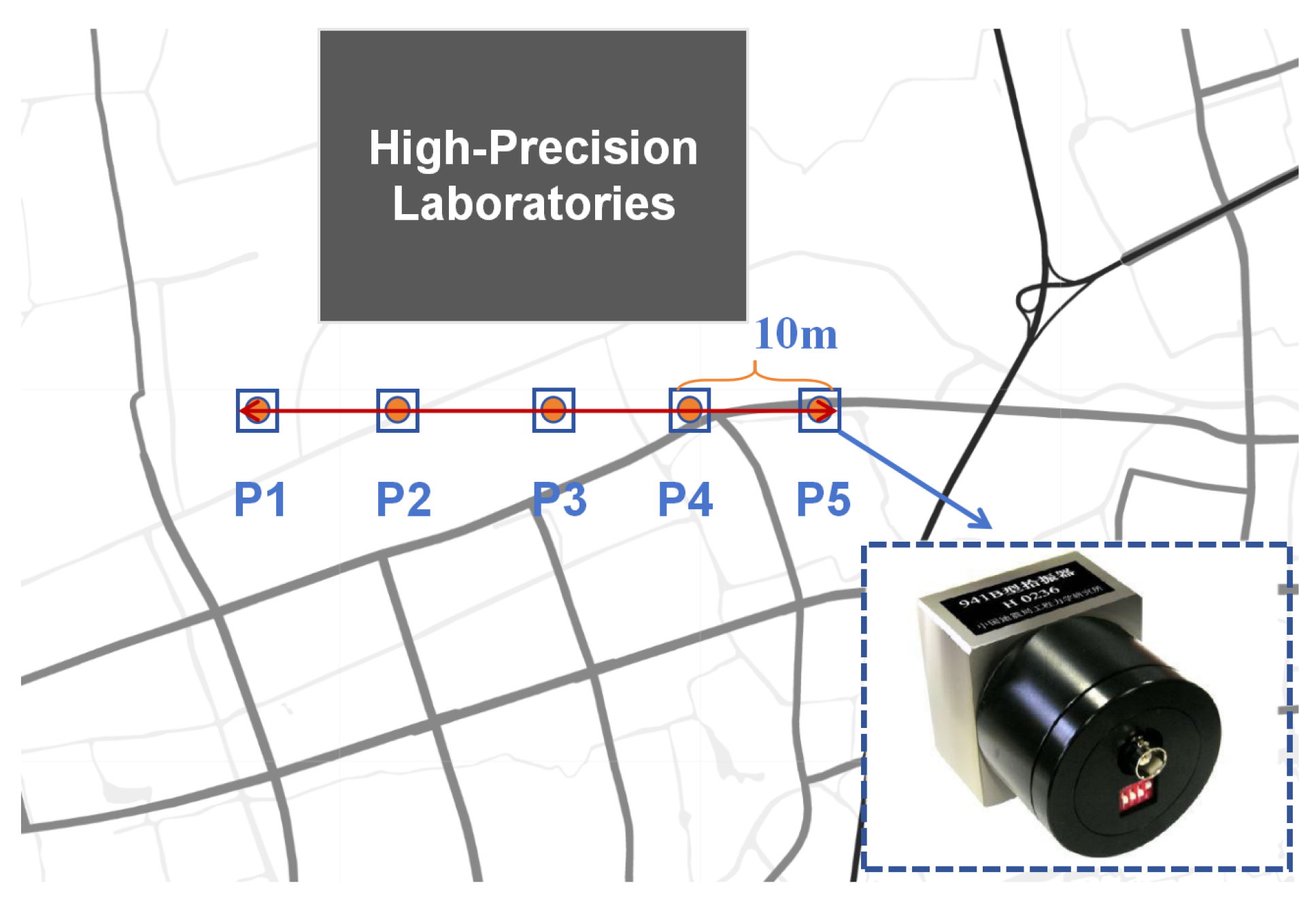
3.2. Measurements and Model Validation

To validate the reliability and accuracy of the vibration simulation results, comparisons were made with on-site measurements and methods adopted in existing literature [42,43]. Figure 4 illustrates the setup of the on-site experimental tests conducted in the high-precision laboratory. Five measurement points (denoted as P1–P5) were arranged from left to right along one side of the laboratory to form a measurement line. The instrument employed for ground vibration measurements was the 941B velocity transducer supplied by the Institute of Engineering Mechanics of the China Earthquake Administration (IEMCEA). The velocity signal was amplified using a 941B amplifier and then acquired with an NI 9220 data acquisition device manufactured by National Instruments at a sampling frequency of 256 Hz, which is suitable for the generally low frequencies of environmental microvibrations.
An average value of these measurements was taken to represent the passive vibration velocity time history. The results of the one-third octave frequency analysis of these data are presented in Figure 5, where the X-axis, Y-axis, and Z-axis represent the east-west, north-south, and vertical directions, respectively. Compared to the vibration induced by the subway [12], the site microvibration frequency mainly concentrates in the low-frequency range of 0–10 Hz, with amplitudes significantly smaller than those induced by the subway, presenting a stable random fluctuation.
Existing research methods often utilize the vibration responses measured at limited points as the vibration input for models. For instance, Gao et al. [43] used ground-measured acceleration as the input load to study the vibration reduction effect of pile-raft foundations on high-tech electronic factory buildings. Such an empirical point vibration input method in the literature serves as a comparative benchmark for assessing the accuracy of our vibration attenuation analysis.
Figure 6 illustrates a comparative study of the horizontal and vertical velocity predictions against on-site measurements and the empirical point vibration input method. In the comparison of horizontal velocities in Figure 6a, the root mean square error (RMSE) between the predicted and actual measured results is 7.38 × 10 7 , while the RMSE between the empirical point vibration input results and the actual measured results is 2.14 × 10 6 . This indicates a close correlation between the predicted and actual measured results, with both showing similar fluctuation patterns over time. The empirical point vibration input method follows the same general trend but with a notable variance in amplitude when compared to the actual measurements. Similarly, in the comparison of vertical velocities in Figure 6b, the RMSE between the predicted and actual measured results is 8.33 × 10 6 , while the RMSE between the empirical point vibration input results and the actual measured results is 1.11 × 10 5 , capturing the initial transient response and the following vibration behavior. The empirical point vibration input method exhibits a comparable trend but with a noticeably higher deviation from the measured data, especially in the post-transient phase.
Discrepancies between the predicted and measured vibration values still exist, and the possible reasons include the following: (1) simplified treatment of soil stratification distribution within the model, whereas the actual site’s soil distribution exhibits uncertainties; (2) in practice, building structures are subjected to random vibrations from various directions, which are highly complex. The vibration input of this model has not achieved corresponding complexity. Overall, the predicted vibration values are in relatively good agreement with the measured values and are more accurate compared to empirical point methods. Therefore, the differences between predicted and actual values are deemed acceptable. This comparative analysis verifies the predictive accuracy of our proposed vibration attenuation input method for capturing the complex dynamics of site-specific vibrations.

4. Analysis of Vibration Isolation Efficacy of Various Interventions

4.1. Analysis of Vibration Isolation Effects of Pile Length

This research involved an analysis of four distinct pile length configurations to assess their respective impacts on vibration isolation efficacy: an absence of piles (0 m) and the installation of short (14 m), medium (28 m), and long piles (42 m). The baseplate of the pile foundation was 50 m × 50 m × 1 m, with each pile featuring a diameter (d) of 1 m and inter-pile spacing (s) of 3 m. The pile foundations were made of reinforced concrete, characterized by material parameters including the following: elastic modulus E c = 30 GPa, density ρ = 2500 Kg/ m 3 , Poisson’s ratio υ = 0.2 , and damping ratio ζ = 0.02 . The piles were computationally modeled as line elements, uniformly distributed beneath the baseplate, penetrating into the subsoil strata.
Figure 7 presents the velocity spectra at the center of the foundation baseplate in the X, Y, and Z principal directions for each pile length scenario. The findings reveal that enhancements in pile length correspond to substantial improvements in vibration isolation capabilities in all three spatial directions. This effect is primarily ascribed to the expanded interaction surface area between the piles and the soil, which, in turn, bolsters the dynamic stiffness of the system. The elongated piles interact with deeper soil strata, intensifying the damping properties of the pile assembly and facilitating efficient absorption of ambient environmental vibrations. Specifically, as the pile length is extended from 0 m to 14 m, the peak velocity of vibration at the foundation’s surface decreases by 26%, indicating a significant attenuation effect. The most notable attenuation in vibration speed is observed when the pile length is extended from 0 m to 14 m. Subsequent increases in pile length induce the pile tips to penetrate into more compliant soil layers, which diminishes the attenuation efficiency.
Additionally, while elongating the pile length exhibits a modest influence on mitigating vibrations within the high-frequency domain for the X and Y directions, it demonstrates pronounced attenuation across the entire frequency spectrum in the Z direction. Relative to the scenario devoid of piles, the introduction of short, medium, and long piles yields significant diminutions in peak vibration velocity at the foundation’s surface, with respective attenuation rates of 27.6%, 33.3%, and 38.6%. In conclusion, appropriately extending the pile length within a specified range can effectively enhance the vibration isolation capabilities of pile foundations, particularly in reducing vertical vibrations.

4.2. Analysis of Vibration Isolation Effects of Foundation Burial Depth

In engineering practice, the depth of foundation not only provides sturdy support to the superstructure but also plays an instrumental role in attenuating extrinsic vibrations [44]. This investigation formulated five distinct scenarios with varying burial depths (h): 0 m, 5 m, 10 m, 15 m, and 20 m, all while maintaining the pile spacing at 3 m, the pile diameter (d) at 1 m, and the pile length (l) at 14 m, with other parameters held constant.
Figure 8 illustrates the spectral characteristics of vibration velocities at the foundation’s central baseplate surface along the X, Y, and Z directions, corresponding to the aforementioned burial depths. The analysis showcases marked disparities in vibration isolation properties at the central point of the pile foundation surface, inversely correlating the amplitude of velocity at the foundation’s surface center with increasing burial depth. This trend is primarily attributed to the augmented vibration isolation afforded by deeper foundations from surface-level disturbances, including traffic and industrial operations. An increment in burial depth enhances the soil’s damping properties, consequently curtailing the transmission of vibration energy.
Throughout the frequency spectrum, the vibration velocity amplitudes in the X, Y, and Z directions follow a pattern of initial increase followed by a decrease. In the low-frequency domain, deepening the foundation’s burial depth does not notably heighten vibration isolation in the Z direction; however, it exhibits pronounced isolation performance in the X and Y directions. In the mid-to-high-frequency spectrum, increasing the pile foundation burial depth effectively reduces the vibration at the surface center point. The vibration isolation effect significantly improves when the burial depth increases from the surface level to 15 m, yet it subsides at a 20 m depth, potentially due to the foundation being situated in a silty soil layer, which amplifies environmental microvibrations. Compared with a surface-level foundation, the peak vibration attenuation rates at the foundation surface center, corresponding to depth increments from 5 m to 20 m, are 7.5%, 16.3%, 23.2%, and 25.4%, respectively. In summary, this analysis reveals that the burial depth significantly influences the vibration isolation performance of pile foundations within a certain range. However, the specific conditions of the soil strata and groundwater levels should be duly considered to ascertain whether the foundation is embedded within more stable soil layers, optimizing its vibration isolation potential.

4.3. Analysis of Vibration Isolation Effects of Slab Thickness

To investigate the influence of different concrete baseplate thicknesses (t) on the vibration isolation properties of pile foundations, four distinct scenarios were established featuring baseplates with thicknesses of 0.5 m, 1 m, 1.5 m, and 2 m. The length and width of these concrete baseplates were consistently maintained at 50 m × 50 m, positioned at the soil surface level, with all other parameters kept constant.
Figure 9 exhibits the velocity spectra at the center point of the pile foundation baseplate surface, analyzed through one-third octave band analysis, across these varying thickness scenarios in the X, Y, and Z directions. The findings demonstrate a significant reduction in vibration response at the central point with increasing baseplate thickness, affecting the entire frequency spectrum. Specifically, in the mid-to-high-frequency domain, increasing the thickness of the concrete baseplate significantly reduces the velocity vibration amplitude. However, in the low-frequency spectrum, adjustments in baseplate thickness appear to exert minimal impact on vibration attenuation at the foundation surface, possibly due to the pervasive nature of low-frequency vibrations.
The overall trend of the vibration velocity amplitude at the foundation surface center point in the X, Y, and Z directions is similar, with only minor differences observed in the high-frequency range between 50 Hz and 100 Hz. The vibration energy in the X and Y directions predominantly concentrates around 3.15 Hz, whereas in the Z direction, it is centered near 5 Hz. When enhancing the baseplate thickness, it is pivotal to circumvent alignment of the foundation’s natural frequency with the frequency of the vibration source. As the baseplate thickness increases from 0.5 m to 2 m, the vibration response attenuation rates at the center point reach 14.6%, 26.7%, and 33.1%, respectively. The increased thickness of the baseplate not only enhances the stiffness and structural mass of the entire foundation but also more effectively disperses vibration energy, thereby significantly improving the overall vibration isolation performance of the foundation.
Comparing these three vibration isolation methods mentioned above: increasing the length of pile foundations demonstrates significant damping effectiveness in the vertical direction. Nonetheless, during the design phase, it is crucial to take into account the geological characteristics of the soil strata to prevent the extended pile foundations from resting on weak soil layers. Deepening the foundation depth is shown to offer the optimum vibration isolation effect within a certain threshold, specifically around 15 m according to our study. Further deepening does not significantly enhance vibration isolation performance and could lead to increased construction costs. Augmenting the thickness of the baseplate yields favorable vibration isolation effects across all three axes; however, in the low-frequency range, resonance phenomena may diminish the efficacy of vibration isolation.

5. Conclusions

Through field experiments, numerical simulations, and theoretical analysis, this study proposes a finite element analysis method to investigate the propagation and attenuation of sourceless vibrations with depth. This approach has been applied to assess the effects of vibration isolation for pile foundation parameter settings in high-precision laboratories. This method can be effectively applied to the prediction of passive vibration, addressing the uncertainty of the vibration source and reducing the time and monetary costs associated with measured vibrations at depths below the surface. The main findings of this study can be summarized as follows:
(1) Combining in situ measurements of ground vibrations and the dispersion characteristics of Rayleigh waves, the attenuation of vibration velocities at various frequencies with depth in layered soils was obtained. The vibration time history at the boundary nodes of the finite element model was solved as input, enabling the finite element calculations to simulate the actual vibration response more accurately.
(2) Compared to the existing empirical point vibration input methods, the analytical approach proposed in this study exhibited a higher consistency with field measurement results under passive conditions of environmental microvibrations, thereby more effectively capturing both the initial transient response and the subsequent vibration behavior.
(3) The vibration isolation effects observed across different pile foundation configurations indicated that extending the pile length, increasing the foundation’s burial depth, and thickening the concrete baseplate significantly enhanced the vibration isolation performance. These measures, by improving the interaction with deeper soil layers and increasing the foundation’s stiffness and mass, effectively dispersed the vibration energy, achieving optimized vibration isolation capabilities.

Author Contributions

Conceptualization, Y.C. and C.S.; Methodology, Y.C. and K.L.; Software, Y.C. and F.D.; Validation, Y.C.; Data analysis, Y.C.; Investigation, Y.C.; Resources, Q.H.; Data curation, Y.C.; Writing—original draft preparation, Y.C.; Writing—review and editing, Y.C. and K.L.; Supervision, C.S.; Project administration, Y.C. All authors have read and agreed to the published version of the manuscript.

Funding

This research was funded by the National Natural Science Foundation of China (grant No. 51678361), to which the authors are very grateful.

Data Availability Statement

The original contributions presented in the study are included in the article, further inquiries can be directed to the corresponding authors.

Conflicts of Interest

Author Qiuju Huang was employed by the company China Aviation Planning and Design Institute (Group) Co., Ltd. The remaining authors declare that the research was conducted in the absence of any commercial or financial relationships that could be construed as a potential conflict of interest.

References

  1. Hessouh, J.J.; Eslami, J.; Beaucour, A.L.; Noumowe, A.; Mathieu, F.; Gotteland, P. Physical and mechanical characterization of deep soil mixing (DSM) materials: Laboratory vs construction site. Constr. Build. Mater. 2023, 368, 130436. [Google Scholar] [CrossRef]
  2. Zhu, Z.; Zhou, Y.; Tan, Z.; He, H.; Zhou, X. Application of tuned viscous mass damper isolation systems for equipment-induced vibration control of industrial buildings. Structures 2023, 51, 1934–1943. [Google Scholar] [CrossRef]
  3. Yu, P.; Zhang, Y.; Gao, Z.; Song, W.; Zhao, Y. Structural microvibration monitoring and simulation analysis of the proton service building based on the construction process. Structures 2020, 27, 1841–1850. [Google Scholar] [CrossRef]
  4. Connolly, D.P.; Marecki, G.P.; Kouroussis, G.; Thalassinakis, I.; Woodward, P.K. The growth of railway ground vibration problems—A review. Sci. Total. Environ. 2016, 568, 1276–1282. [Google Scholar] [CrossRef] [PubMed]
  5. GB51076-2015; Technical Specification for Anti-Vibration Engineering in the Electronic Industry. China Planning Press: Beijing, China, 2015.
  6. Zhang, Z.; Li, X.; Zhang, X.; Fan, J.; Xu, G. Semi-analytical simulation for ground-borne vibration caused by rail traffic on viaducts: Vibration-isolating effects of multi-layered elastic supports. J. Sound Vib. 2022, 516, 116540. [Google Scholar] [CrossRef]
  7. Ulgen, D.; Ertugrul, O.; Ozkan, M. Measurement of ground borne vibrations for foundation design and vibration isolation of a high-precision instrument. Measurement 2016, 93, 385–396. [Google Scholar] [CrossRef]
  8. Calvo, J.; Álvarez-Caldas, C.; San Román, J.; Cobo, P. Influence of vehicle driving parameters on the noise caused by passenger cars in urban traffic. Transp. Res. Part D Transp. Environ. 2012, 17, 509–513. [Google Scholar] [CrossRef]
  9. Vestad, H.; Steinert, M. A low-cost vibration isolation chamber–Making high precision experiments accessible. HardwareX 2022, 11, e00264. [Google Scholar] [CrossRef] [PubMed]
  10. Xia, H.; Cao, Y.; De Roeck, G. Theoretical modeling and characteristic analysis of moving-train induced ground vibrations. J. Sound Vib. 2010, 329, 819–832. [Google Scholar] [CrossRef]
  11. Mhanna, M.; Sadek, M.; Shahrour, I. Numerical modeling of traffic-induced ground vibration. Comput. Geotech. 2012, 39, 116–123. [Google Scholar] [CrossRef]
  12. Huang, S.; Chen, Y.; Zou, C.; Jian, S. Train-induced environmental vibrations by considering different building foundations along curved track. Transp. Geotech. 2022, 35, 100785. [Google Scholar] [CrossRef]
  13. Gu, X.-q.; Yu, K.-y.; Huang, M.-s.; Liu, X.; Yan, F.; Wu, D.-s. Finite element method for analyzing environmental vibration without apparent sources and its application in Beijing High-Energy Photon Source. Chin. J. Geotech. Eng. 2022, 44, 2245–2252. [Google Scholar]
  14. Jain, A.; Soni, D. Foundation vibration isolation methods. In Proceedings of the 3rd WSEAS International Conference on Applied and Theoretical Mechanics, Tenerife, Canary Islands, Spain, 14–16 December 2007; pp. 14–16. [Google Scholar]
  15. Ma, M.; Li, M.; Qu, X.; Zhang, H. Effect of passing metro trains on uncertainty of vibration source intensity: Monitoring tests. Measurement 2022, 193, 110992. [Google Scholar] [CrossRef]
  16. Lysmer, J.; Waas, G. Shear waves in plane infinite structures. J. Eng. Mech. Div. 1972, 98, 85–105. [Google Scholar] [CrossRef]
  17. Woods, R.D. Screening of surface wave in soils. J. Soil Mech. Found. Div. 1968, 94, 951–979. [Google Scholar] [CrossRef]
  18. Huang, M.S.; Ren, Q.; Zhou, R.Y.; Huang, S.M. Attenuation characters of Rayleigh wave in layered soils. Yantu Lixue/Rock Soil Mech. 2009, 30, 113–122. [Google Scholar]
  19. Yu, K.; Gu, X.; Huang, M.; Ma, X.; Li, N. Experimental, numerical and analytical studies on the attenuation of maglev train-induced vibrations with depth in layered soils. Soil Dyn. Earthq. Eng. 2021, 143, 106628. [Google Scholar] [CrossRef]
  20. Ren, X.; Wu, J.; Tang, Y.; Yang, J. Propagation and attenuation characteristics of the vibration in soft soil foundations induced by high-speed trains. Soil Dyn. Earthq. Eng. 2019, 117, 374–383. [Google Scholar] [CrossRef]
  21. Picoux, B.; Le Houedec, D. Diagnosis and prediction of vibration from railway trains. Soil Dyn. Earthq. Eng. 2005, 25, 905–921. [Google Scholar] [CrossRef]
  22. Tang, Y.; Yang, Q.; Ren, X.; Xiao, S. Dynamic response of soft soils in high-speed rail foundation: In situ measurements and time domain finite element method model. Can. Geotech. J. 2019, 56, 1832–1848. [Google Scholar] [CrossRef]
  23. Woods, R.D.; Barnett, N.E.; Sagesser, R. Holography—A new tool for soil dynamics. J. Geotech. Eng. Div. 1974, 100, 1231–1247. [Google Scholar] [CrossRef]
  24. Gupta, S.; Degrande, G.; Chebli, H.; Clouteau, D.; Hussein, M.; Hunt, H. A coupled periodic fe-be model for ground-borne vibrations from underground railways. In Proceedings of the 3rd European Conference on Computational Mechanics, Lisbon, Portugal, 5–8 June 2006. [Google Scholar]
  25. Kuznetsov, S. Seismic waves and seismic barriers. Acoust. Phys. 2011, 57, 420–426. [Google Scholar] [CrossRef]
  26. Chanda, A.; Barman, S.; Sahoo, T.; Meylan, M. Flexural-gravity wave scattering by an array of bottom-standing partial porous barriers in the framework of Bragg resonance and blocking dynamics. Phys. Fluids 2024, 36, 012129. [Google Scholar] [CrossRef]
  27. Rojas, O.S.; Jerves, A.; Medina, D. A Nonlinear Lagrangian Model for Plane Frames Pre-design. J. Appl. Comput. Mech. 2023, 9, 884–899. [Google Scholar]
  28. Zou, C.; Wang, Y.; Tao, Z. Train-induced building vibration and radiated noise by considering soil properties. Sustainability 2020, 12, 937. [Google Scholar] [CrossRef]
  29. López-Mendoza, D.; Romero, A.; Connolly, D.P.; Galvín, P. Scoping assessment of building vibration induced by railway traffic. Soil Dyn. Earthq. Eng. 2017, 93, 147–161. [Google Scholar] [CrossRef]
  30. Sadeghi, J.; Vasheghani, M. Safety of buildings against train induced structure borne noise. Build. Environ. 2021, 197, 107784. [Google Scholar] [CrossRef]
  31. Yao, J.; Xia, H.; Zhan, N. Study on the Train-induced Environmental Vibrations Considering Soil-Structure Interaction. Procedia Eng. 2017, 199, 2747–2752. [Google Scholar] [CrossRef]
  32. Yang, Y.; Hung, H.; Chang, D. Train-induced wave propagation in layered soils using finite/infinite element simulation. Soil Dyn. Earthq. Eng. 2003, 23, 263–278. [Google Scholar] [CrossRef]
  33. Ren, Y.; Qu, S.; Yang, J.; Li, Q.; Zhu, B.; Zhai, W.; Zhu, S. An efficient three-dimensional dynamic stiffness-based model for predicting subway train-induced building vibrations. J. Build. Eng. 2023, 76, 107239. [Google Scholar] [CrossRef]
  34. Thompson, D.J.; Kouroussis, G.; Ntotsios, E. Modelling, simulation and evaluation of ground vibration caused by rail vehicles. Veh. Syst. Dyn. 2019, 57, 936–983. [Google Scholar] [CrossRef]
  35. Li, X.; Chen, Y.; Zou, C.; Chen, Y. Train-induced vibration mitigation based on foundation improvement. J. Build. Eng. 2023, 76, 107106. [Google Scholar] [CrossRef]
  36. He, Y.; Peng, L.; He, K.; Guan, Q.; Han, J.; Xiao, X.; Sheng, X. Analysis of uncertainty and variation in underground train-induced vibration based on measured data. Measurement 2023, 222, 113600. [Google Scholar] [CrossRef]
  37. Zerwer, A.; Cascante, G.; Hutchinson, J. Parameter estimation in finite element simulations of Rayleigh waves. J. Geotech. Geoenviron. Eng. 2002, 128, 250–261. [Google Scholar] [CrossRef]
  38. Qu, S.; Yang, J.; Feng, Y.; Peng, Y.; Zhao, C.; Zhu, S.; Zhai, W. Ground vibration induced by maglev trains running inside tunnel: Numerical modelling and experimental validation. Soil Dyn. Earthq. Eng. 2022, 157, 107278. [Google Scholar] [CrossRef]
  39. Aki, K.; Richards, P.G. Quantitative Seismology; University Science Books: Herndon, VA, USA, 2002. [Google Scholar]
  40. Gao, G.y.; Song, J.; Yang, J. Identifying boundary between near field and far field in ground vibration caused by surface loading. J. Cent. South Univ. 2014, 21, 3284–3294. [Google Scholar] [CrossRef]
  41. Connolly, D.P.; Kouroussis, G.; Laghrouche, O.; Ho, C.; Forde, M. Benchmarking railway vibrations–Track, vehicle, ground and building effects. Constr. Build. Mater. 2015, 92, 64–81. [Google Scholar] [CrossRef]
  42. Gupta, S.; Liu, W.; Degrande, G.; Lombaert, G.; Liu, W. Prediction of vibrations induced by underground railway traffic in Beijing. J. Sound Vib. 2008, 310, 608–630. [Google Scholar] [CrossRef]
  43. Gao, G.; Chen, J.; Yang, J.; Meng, Y. Field measurement and FE prediction of vibration reduction due to pile-raft foundation for high-tech workshop. Soil Dyn. Earthq. Eng. 2017, 101, 264–268. [Google Scholar] [CrossRef]
  44. Zeng, Y.; Pan, P.; Zhang, D.; Yang, J. Experimental study of isolation in the backfill zone of the foundation pit (IBF) method to reduce ground-borne vibration in buildings. Eng. Struct. 2020, 202, 109740. [Google Scholar] [CrossRef]
Figure 1. Schematic of the finite–infinite foundation–soil model.
Buildings 14 01215 g001
Figure 2. Flow chart for calculating the attenuated vibration velocity along depth.
Buildings 14 01215 g002
Figure 3. Depth-dependent attenuation factors of Rayleigh waves in horizontal and vertical orientations: (a) horizontal attenuation factor; (b) vertical attenuation factor.
Buildings 14 01215 g003
Figure 4. Field test plane overview schematic.
Buildings 14 01215 g004
Figure 5. Field measurement data: average surface vibration velocity and one-third octave spectrum: (a) time history curve; (b) 1/3 octave spectrum curve.
Buildings 14 01215 g005
Figure 6. Comparison of predictions with on-site measurements and the empirical point vibration input method: (a) horizontal velocity; (b) vertical velocity.
Buildings 14 01215 g006
Figure 7. Impact of pile length variation on vibration isolation performance.
Buildings 14 01215 g007
Figure 8. Impact of burial depth variation on vibration isolation performance.
Buildings 14 01215 g008
Figure 9. Impact of slab thickness variation on vibration isolation performance.
Buildings 14 01215 g009
Table 1. Soil layers and their properties at the high-precision laboratory site.
Soil LayersThickness (m)Density ρ ( kg · m 3 )Poisson’s Ratio υ Module of Elasticity E (MPa)Shear Wave Velocity V s (m · s 1 )
Back fill218800.4085.9127.7
Silty clay318700.3590.4133.8
Sandy clay618700.42100.1137.3
Sandy silt-like cohesive soil418900.42123.6151.7
Silty clay1216600.32102.4152.9
Clay1417400.39200.4203.5
Silty clay919400.39226.1211.7
Disclaimer/Publisher’s Note: The statements, opinions and data contained in all publications are solely those of the individual author(s) and contributor(s) and not of MDPI and/or the editor(s). MDPI and/or the editor(s) disclaim responsibility for any injury to people or property resulting from any ideas, methods, instructions or products referred to in the content.

