Article

Design and Performance Assessment of Base Isolated Structures Supplemented with Vibration Control Systems

by
Evangelos Sapountzakis
,
Georgios Florakis
* and
Konstantinos Kapasakalis
Institute of Structural Analysis and Antiseismic Research, School of Civil Engineering, National Technical University of Athens, Zografou Campus, GR-157 80 Athens, Greece
*
Author to whom correspondence should be addressed.
Buildings 2024, 14(4), 955; https://doi.org/10.3390/buildings14040955
Submission received: 21 February 2024 / Revised: 20 March 2024 / Accepted: 28 March 2024 / Published: 30 March 2024
(This article belongs to the Special Issue Sustainable Preservation of Buildings and Infrastructure)

Abstract

:
This paper investigates the implementation of supplemental vibration control systems (VCS) in base isolated (BI) structures, to improve their dynamic performance. More specifically, the aim of the VCS is to reduce the base displacement demand of BI structures, and at the same time mitigate the superstructure seismic responses. The purpose of the examined VCS is dual, and for this reason a multi-objective optimization methodology is formulated for the design of the VCS. The examined vibration absorbers include modifications of the KDamper concept. The KDamper is an extension of the traditional Tuned Mass Damper (TMD), and introduces a negative stiffness (NS) element to the additional oscillating mass of the TMD. The generated NS force is exactly in phase with the inertia force of the added mass, thus, artificially amplifying it. This way, lighter configurations are possible with an enhanced damping behavior. These VCS are designed based on engineering criteria and manufacturing constraints, while the excitation input used in the multi-objective optimization procedure is selected from a dataset of artificial accelerograms, designed to be spectrum-compatible with the EC8 design acceleration response spectrum. The effectiveness of the examined VCS is also assess with real near-fault earthquake records, and a comparison is performed with TMD-based VCS having 50 times larger additional masses. The numerical results demonstrate the superiority of the KDamper-based VCS in improving the dynamic behavior of BI structures over other mass-related systems (TMD).

1. Introduction

Seismic protection of structures has been a topic of extensive research in the past few years, with a particular focus on the development and application of novel passive structural control techniques. Passive systems [1] are designed to dissipate or redirect seismic energy transmitted to structures, thereby enhancing structural safety and integrity. Since they do not need power to operate, they are considered more reliable compared to active [2] or semi-active [3] control systems which can be affected from power outages during a seismic event. Moreover, they are generally cost-efficient, have low maintenance requirements and are easily integrated into various structural configurations.
Among the various passive control systems, base isolation [4] has gained significant popularity and is recognized as the most effective method of mitigating the impact of seismic events, not only on structural, but also on non-structural components and building contents [5]. The fundamental idea behind seismic base isolation lies in the insertion of a group of low-stiffness elements between the foundation and the structure. The purpose is to shift the structure’s fundamental frequency away from both its fixed-base frequency and the predominant frequencies of ground motion, this way mitigating the seismic forces and structural accelerations. The most popular elements used to comprise the isolation layer are the elastomeric [6] and lead rubber bearings [7]. As an alternative to elastomeric bearings, great effort has been made to enable the use of unbounded fiber reinforced elastomeric bearings, as described in [8].
The conventional bearings are designed to have low horizontal stiffness in order to achieve effectively the structure-foundation decoupling under lateral forces (earthquake, wind), and high vertical stiffness to carry the large axial structural loads. In addition to effective energy dissipation, these elements provide practical solutions for seismic resilience [9], they are cheap to manufacture and need no maintenance [10]. Nevertheless, due to their limited horizontal stiffness, the use of bearings can lead to significant structural displacements during an earthquake. These displacements may result not only in bearing damages but also in collisions between buildings, especially in densely built-up areas. Apart from bearings, alternative devices that exhibit high energy dissipation capacity are the seismic dampers as proposed in studies [11,12,13,14].
To overcome the displacement demand of bearings, a control strategy that combines the Tuned Mass Damper (TMD) with the base isolation concept has been studied extensively in the past few years [15,16,17,18]. The TMD typically consists of a spring, a damper element and a mass (referred to as additional mass) which are attached to the main vibrating system. By optimally tuning its parameters [19], the TMD can effectively reduce the unfavorable displacements by controlling the relative movement at the isolation level. However, temperature variations and other environmental conditions can alter the stiffness and damping properties of the TMD leading to detuning, which could significantly compromise its performance [20]. Furthermore, according to previous research [21], the greater the additional mass of the TMD, the more effective its control effect over the structure. Nevertheless, a large oscillating mass render the construction and implementation of the TMD in the base of the structure extremely challenging due to geometric and other limitations imposed by the respective structural system.
To enhance the effectiveness of the TMD without directly increasing its mass, researchers have proposed the use of supplementary inertial mass dampers. This innovative control strategy, often referred to as TMDI (Tuned Mass Damper Inerter) exploits the mass-amplification effect of the inerter [22], a two-terminal mechanical element that generates a force proportional to the relative acceleration between its terminals. The promising outcomes of the TMDI in numerous mechanical and civil engineering applications [23,24,25], have prompted its examination in conjunction with conventional base isolated structures [26,27,28]. In these studies, the dynamic performance of the structure is improved, however not significantly when compared to a TMD with a large additional mass or a base isolation system utilizing high damping rubber bearings [29,30].
An alternative approach to indirectly augment the inertia of an oscillating system is by incorporating a negative stiffness (NS) element [31,32]. Negative stiffness isolators have attracted considerable attention in the field of seismic protection [33,34,35,36,37] due to their ability to mitigate the dynamic responses of the system, without increasing structural accelerations, while limiting the displacement of the isolation level. These devices store a pre-compressive force that during the seismic event generates a destabilizing effect, which reduces the overall stiffness. As a result the structures experience enhanced vibration isolation and shock attenuation across a broad spectrum of frequencies. Implementations of passive NS devices in seismically isolated structures [38,39,40,41,42] have demonstrated the effectiveness of the supplemental isolation systems in enhancing the overall dynamic performance of these structures. However, if the deformation of the existing bearings suppresses a specific threshold, significant displacements may arise.
A novel passive seismic absorber, which combines the concepts of TMD and NS, was introduced in [43] and is referred to as KDamper. It is a variant of the traditional TMD oscillator, distinguished by the addition of a NS element that connects the additional mass to the foundation beneath the isolation level (the ground in the case of base isolation). This device offers exceptional damping properties and due to the use of the NS element it can increase indirectly the inertia effect of its mass, while simultaneously controlling its tuning. As a result, it effectively overcomes the main drawbacks of the TMD. The use of the KDamper in seismic base absorption of buildings [44] and bridges [45], demonstrated that the device can drastically reduce the dynamic responses of the controlled structure under seismic excitations. An extension of the KDamper, named Extended KDamper (EKD), was proposed in [46]. It is differentiated from the initial design due to: (i) the placement of the NS element between the isolation level and the additional mass and (ii) the installation of an extra artificial damper parallel to the NS element. The performance of the EKD in providing horizontal seismic protection for buildings has been studied in [47,48] and an indicative design of the device was conducted in [49]. It has been also tested as a vertical seismic absorber [50,51,52] and as a vibration control strategy of wind turbine towers [53,54]. Another variant of the KDamper, the SBA (Seismic Base Absorber), which consists of the EKD connected in parallel with an inerter element has also been investigated [55,56]. In [57], a novel design for the NS element of the SBA was proposed, the performance of the device was examined and an indicative placement in the base of a structure was suggested. The aim of the SBA is to further reduce structural accelerations while more effectively controlling displacements compared to the other KDamper designs.
This paper investigates the performance enhancement of an existing base isolated multi-story structure by adding supplemental vibration control systems (VCS) at the isolation level. These systems include various modifications of the KDamper concept and TMD, TMDI devices with different mass ratios. Although the KDamper modifications have been proven effective in the context of alternative seismic absorption bases, according to the literature, their performance as supplements in existing base isolated structures has not yet been examined.
Section 2 of this work presents the configurations of the examined VCS, along with the equations of motion and parameters of the base isolated multi-story structure equipped with each of these systems. In Section 3, a multi-objective constrained optimization methodology of a 5-story building equipped with the VCS is formulated, employing the modified Non-Sorting Genetic Algorithm type II (NSGA-II) enhanced with the crowding distance operator (CDO) [58]. The objective functions and the design variables along with their boundaries are selected. Furthermore, the fixed parameter values for the KDamper-based VCS are defined and the calculation process of their stiffness elements is presented. In Section 4, the Pareto fronts are provided, illustrating the minimization of the objective functions as calculated from the corresponding optimal solutions sets of each system. For the optimization process and the dynamic analysis of the controlled 5-story building, a database of 30 artificial accelerograms is chosen as the excitation input, designed to be spectrum-compatible with the EC8 acceleration design response spectrum. For comparative purposes, the Pareto fronts of the best KDamper-based VCS and TMD-based VCS are also depicted. These systems are further compared in Section 5 with real earthquake records, in terms of absolute maximum dynamic responses, after selecting for each system one of their optimal solutions sets. The responses of the conventionally isolated building without VCS are also calculated to highlight the efficacy of integrating the proposed KDamper-based devices into the building. For the dynamic analysis conducted in this section, a group of 10 near-fault real records along with 10 artificial accelerograms are used as excitation input. Lastly, in Section 6, the key findings of this study are summarized.

2. Base Isolated Structure Supplemented with VCS

In this section, various vibration control systems (VCS) are employed as supplements to a conventionally base isolated multi-story structure, to improve its dynamic performance. More specifically, the examined VCS are implemented at the base level of the structure, and aim to reduce the required base displacements, retaining the superstructure seismic responses in reasonable ranges. A schematic representation of the controlled structure with the examined VCS configurations is presented in Figure 1.
The superstructure is modelled as a lumped mass model, under the following assumptions: (i) the total structural mass is concentrated at the floor levels, (ii) the floor slabs and grinders are rigid compared to the columns, (iii) the columns are axially inextensible, and (iv) the superstructure remains elastic during the analysis.
The base isolation layer is modelled as linear, by means of the effective stiffness and the equivalent viscous damping. Since the conventional base isolated structure employs low damped rubber bearings, analytical or differential models [59,60] are not considered necessary for the simulation of the isolation base. The equations of motion of the base isolated structure (BI), without a VCS, can be thus expressed in a matrix form as:
M B I u ¨ B I + C B I u ˙ B I + K B I u B I = M B I I T x ¨ G
where u i = x i x G . The matrices of mass, damping, and stiffness entering Equation (1) are:
M ( n + 1 ) × ( n + 1 ) = M S T R n × n 0 n × 1 0 1 × n m B
C ( n + 1 ) × ( n + 1 ) = C S T R n × n 0 n × 1 0 1 × n c B
K ( n + 1 ) × ( n + 1 ) = K S T R n × n K S T R B I n × 1 T K S T R B I 1 × n k B
K S T R B I 1 × n = k 1 0 1 × ( n 1 )
In the case a multi-story structure is mounted on an isolation base, the base level is significantly more flexible as compared to the superstructure. As a result, the fundamental frequency of the BI structure is greatly reduced, and the structure seismic responses are primarily affected by the first mode of the system. Thus, the BI structure can be characterized by the base isolation frequency and damping ratio, defined as follows:
ω B = 2 π f B = k B M t o t
ζ B = c B 2 m B ω B
where M t o t is the total mass of the structure including the mass of the base slab. The equations of motion of the BI structure supplemented with a VCS are:
M V C S u ¨ V C S + C V C S u ˙ V C S + K V C S u V C S = M V C S ( e f f ) I T x ¨ G
The mass matrix on the right hand side of Equation (4) differs from the one on the left, due to the introduction of inertance elements. Inerters generate inertia forces proportional to the relative acceleration between their terminals, and thus affect the mass matrix ( M V C S ), however, they do not provide actual mass on the structure, and as a result, they do not influence the seismic induced forces ( M V C S ( e f f ) I T x ¨ G ). More details regarding the matrices entering Equation (4) are provided in Appendix A.

2.1. TMD-Based VCS

The TMD-based VCS are presented in Figure 1. The additional oscillating mass of the TMD m T M D is attached to the base level with a positive stiffness element k T M D and an artificial damper c T M D . The free design variables of the BI structure equipped with a conventional TMD are the mass ratio μ T M D , tuning frequency ratio t T M D , and damping ratio ζ T M D , defines as:
μ T M D = m T M D M t o t
t T M D = f T M D f B
f T M D = 1 2 π k T M D m T M D
ζ T M D = c T M D 2 m T M D ω T M D
For the TMDI configuration, Equations (5)–(7) still apply (with annotation TMDI instead of TMD), while an additional design parameter is introduced, the inertance ratio:
b T M D I = B T M D I M t o t
TMD-based VCS are usually tuned to the fundamental frequency of the structure, which in this case is the base isolation frequency f B , in order to reduce the base displacement demand. In this research study, the TMD frequency f T M D is set as a free design variable to explore a broader range of TMD-based VCS effectiveness. The modification of the mass, damping, and stiffness matrices due to the inclusion of the TMD and TMDI VCS can be found in Appendix A.

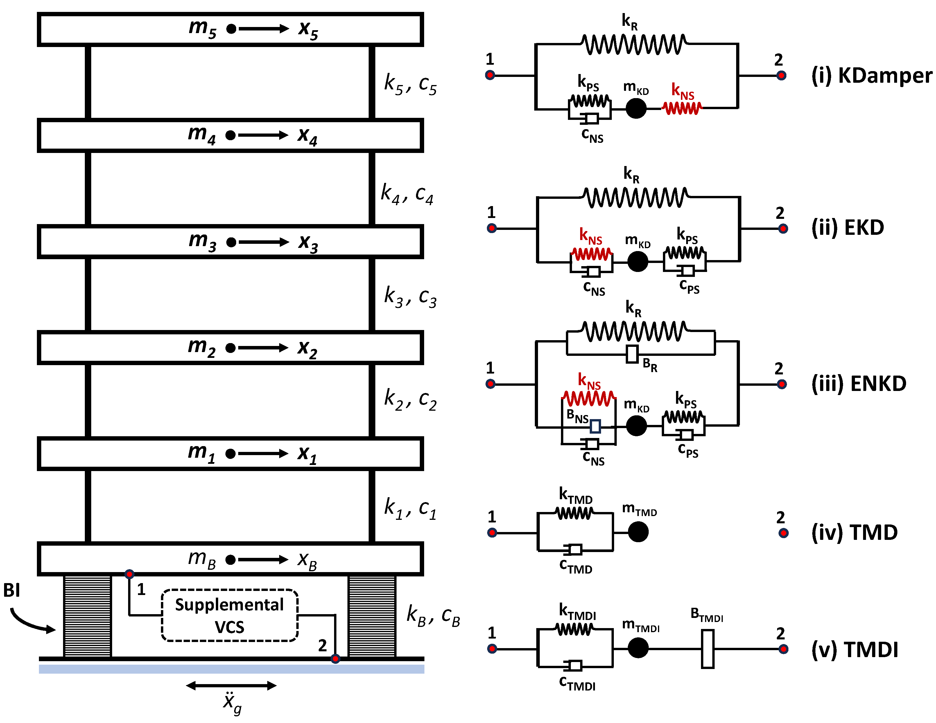
2.2. KDamper-Based VCS

The KDamper-based VCS configurations are illustrated in Figure 1. KDamper introduces an additional mass m K D attached to the isolation floor with a positive stiffness element k P S and an artificial damper c P S , as is in the case of a TMD. Additionally, a negative stiffness (NS) element k N S connects the added mass to the base that artificially amplifies its inertia force, and a positive stiffness element k R is implemented parallel to the base isolation stiffness. With respect to the configuration of the stiffness elements, the EKD and ENKD interchange the positive and negative stiffness elements positions. Since the positive and negative stiffness elements, k P S and k N S , respectively, operate in parallel, the equivalent base stiffness of the BI structure equipped with any KDamper-based design k B K D , can be defined as follows:
k B K D = ( 2 π f B K D ) 2 ( M t o t ) = k B + k R + k N S k P S k N S + k P S
The proposed base isolation VCS supplements based on the KDamper concept introduce NS elements, and thus, it is imperative to ensure the static and dynamic stability of the controlled structure. The stiffness elements’ values can be selected according to Equation (9), however, possible variations in these values, due to temperature variations, manufacturing tolerances, or nonlinear behavior of structural elements that have not been accurately modeled in the mathematical model, may endanger the stability of the system. For this reason, a simultaneous variation in all stiffness elements of the KDmamper-based VCS is accounted for, by introducing a perturbation ε to their values:
k B K D ( ε ) 0 k B + ( 1 ε R ) k R + ( 1 ε P S ) k P S ( 1 + ε N S ) k N S ( 1 ε P S ) k P S + ( 1 + ε N S ) k N S 0
where ε N S , ε P S and ε R are the potential variations to the stiffness elements k N S , k P S and k R , respectively. Assuming that the variations ε are pre-determined, the stiffness elements k P S and k R values result from Equations (9) and (10) as a function of k N S and f B K D . The analytical expressions of k P S and k R are:
k R = k r k B K D
k P S = k p s k B K D
where k r and k p s are obtained from the following relations:
k r = S 2 S 2 2 4 S 1 S 3 2 S 1
k p s = k n s k b k n s k r k n s k b + k r + k n s 1
where k n s = k N S / k B K D and k b = k B / k B K D . Parameters S 1 , S 2 , and S 3 , presented in Equation (12), are defined as:
S 1 = R ( P N )
S 2 = k n s N ( P R ) + k b ( P N ) ( 1 + R ) + R ( N P )
S 3 = k b ( P N ) ( k b 1 ) + N ( P 1 ) k n s k b P N k n s
R = 1 ε R
N = 1 ε N S
P = 1 ε P S
The modification of the mass, damping, and stiffness matrices due to the inclusion of the KDamper, EKD and ENKD VCS can be found in Appendix A.

3. Optimal Design of VCS

The examined VCS are implemented at the base of a seismically isolated multi-story structure to improve its dynamic performance. Specifically, the aim of the VCS is to mitigate the base displacements required to isolate the superstructure from the ground motion. As a result, the VCS has a dual purpose: (i) to reduce the base displacements, and (ii) to mitigate the superstructure dynamic responses. For this reason, a multi-objective optimization problem is formulated in this research study, with the following objective functions (OF):
O F 1 : max | u B | O F 2 : max | a t o p |
where a t o p is the top floor absolute acceleration. For the optimization procedure of the examined VCS, the modified NSGA-II enhanced with the crowding distance operator (CDO) is employed. NSGA-II is an evolutionary algorithm designed to address the challenges associated with multi-parameter and multi-objective optimization problems, and has been effectively applied in seismic protection applications [61]. The framework of this algorithm (NSGA-II with CDO) incorporates the following mechanisms: (i) Crossover and Mutation, (ii) Non-dominated Sorting, (iii) Crowding Distance, and (iv) Tournament Selection. Further details regarding NSGA-II algorithm operators can be found in [62].

3.1. Reference Structure

The reference structure selected as the benchmark building used to assess the performance of the examined VCS and proposed optimization methodology is a five-story reinforced concrete (RC) shear frame building structure, with uniformly distributed masses and stiffnesses for all floors. It represents a mid-rise medium-sized structure and has an elastic modulus of E = 26 GPa. Figure 2 depicts a simple 3D model of this building (without base isolation), along with its floor plan. The floor height is 3 m and the number of columns in each floor is equal to 25. The columns have rectangular cross-sections of 48 cm × 48 cm and a cracked/damaged section has been made. Therefore, the moment of inertia of columns has been reduced by 50%. The floor masses are equal to m F = 360 tn, and correspond to about 400 m2 of floor area and the stiffness of each floor is equal to k F = 650 MN/m.
The damping matrix of the superstructure is calculated under the assumption of modal damping:
C S T R n × n = Φ S T R n × n T C S T R ˜ n × n Φ S T R n × n ,
where C S T R ˜ n × n is a diagonal matrix with the element in the position ( i , i ) defined as 2 ζ i M S T R ( i , i ) ω i . Φ S T R n × n is the matrix of the modal shapes, and ζ i is the damping ratio of the i t h mode. The value of ζ 1 is assumed to be equal to 3.03 % , based on [63], while for the higher modes, the damping ratio is assumed to be proportional to the frequency of the associated structural mode, with a maximum of 10 % critical damping:
ζ i = m i n ζ 1 ω i ω 1 ; 0.1 ,
The reference building is designed assuming the following: ground type C, spectral peak ground acceleration 0.36 g, spectrum type I, and importance class II. For the purpose of this research study, the excitation input in the design optimization process of the examined VCS is selected from a database of 30 artificial accelerograms with response spectrum closely compatible to the EC8 design response spectra, with characteristics that of the reference structure. The database of artificial accelerograms is generated using the SeismoArtif [64].

3.2. TMD-Based Optimal Design

The free design variables of the TMD VCS are presented in Section 2.1, and are the mass ratio μ T M D , tuning frequency ratio t T M D , and damping ratio ζ T M D . The μ T M D can be arbitrarily chosen, and enhances the performance of the TMD the larger it is. The t T M D is selected to vary, with respect to the f B , in order to investigate thoroughly the TMD effectiveness, in the range:
50 % t T M D = f T M D f B 200 % ,
The damping ratio ζ T M D can be calculated analytically base on the minmaxH inf approaches [65], or numerically to minimize a specific response indicator. In this paper, ζ T M D is calculated numerically, and is selected to vary in the range:
ζ T M D = c T M D 2 m T M D ω T M D 50 % ,
In the case of TMDI, an additional constraint is imposed in the inertance b T M D I value:
b T M D I = B T M D I M t o t 40 % ,

3.3. KDamper-Based Optimal Design

The additional oscillating mass m K D in the KDamper-based VCS can be arbitrarily chosen, as in the case of the TMD-based designs. As a result, the free design variables sought in the optimization process of these configurations are:
i.
KDamper: (1) NS element value k N S , (2) nominal base frequency f B K D , and (3) artificial damper value c P S .
ii.
Extended KDamper (EKD): (1) NS element value k N S , (2) nominal base frequency f B K D , (3) and (4) artificial dampers values c P S and c N S .
iii.
EKD enhanced with inerters (ENKD): (1) NS element value k N S , (2) nominal base frequency f B K D , (3), (4) artificial dampers values c P S and c N S , respectively, and (5), (6) inertance ratios b R = B R / M t o t and b N S = B N S / M t o t .
The f K D is set as a design variable of the KDamper-based systems, instead of tuning these VCS with the fundamental structure frequency, in order to obtain their optimum tuning and establish general guidelines. The range in which f B K D varies, is the same as in the case of the TMD-based VCS:
50 % f B f B K D 200 % f B ,
The NS element’s value is another critical parameter, especially for the design of the NS mechanism [46], and its maximum absolute value is upper bounded with respect to the total structural mass M t o t :
k N S 100 k N / m per t n
The artificial dampers c P S and c N S values are upper bounded based on previous research [46], in order to for their realization to be possible with common linear damping devices:
c N S , c P S 5 k N s / m per t n
The values of the inertance ratios are upper bounded per tonne of the superstructure mass M t o t , similarly to the TMD-based VCS:
b R , b N S 40 % ,
The stiffness elements’ variations ε N S , ε P S and ε R are selected to equal to 5%. The NS element k N S is realized with a displacement-dependent configuration that employs pre-compressed positive stiffness elements (spiral springs) and an articulated mechanism. Further details regarding the NS mechanism can be found in [43,46]. In order for the generated NS to remain in the linear regime, and thus, considered in the analysis as linear, the NS stroke (relative displacement between the terminals of the NS mechanism) should be upper bounded:
u N S = u K D 10 cm ( KDamper ) ,
u N S = u B u K D 10 cm ( EKD , ENKD ) ,
The additional mass of all KDamper-based VCS is selected equal to m K D = 0.1 % M t o t (mass ratio equal to 0.1%). This value is significantly lower, as compared to other mass-related VCS found in the literature (TMD, TMDI). For example, the studies in [16,18] examined the TMD for mass ratios ranging from 1% to 10% and it was confirmed that increasing this ratio improves the effectiveness of the TMD. Furthermore, study [28] investigated the performance of a lightweight TMD and TMDI with a mass ratio of 5%, as well as a large mass TMD/TMDI with a ratio of 20%. The efficacy of the KDamper concept with a significantly lower mass ratio is due to its NS element. The force produce from this element artificially amplifies the inertia force of the added mass m K D , as they are exactly in phase [44] and this can be considered as an indirect approach to increase the mass ratio, without actually increasing the additional oscillating mass itself. The benefits of this absorber are: (i) there is no need for heavy parasitic masses, that burden the structure in static and dynamic conditions, in order for the VCS to be effective and (ii) by having a small additional mass, the respective seismic loading is also insignificant.

4. Multi-Objective Optimization Results

The optimization results of the conventionally base isolated 5-story building equipped with the proposed supplemental VCS are depicted in Figure 3. Specifically, Figure 3a illustrates the generated Pareto fronts of the building with the KDamper-based VCS, which include the KDamper, EKD, and ENKD configurations. In Figure 3b, the Pareto fronts of the building equipped with the TMD-based VCS systems with different mass ratios are displayed. The TMD and TMDI systems with a mass ratio of 1% are labelled as TMD-1% and TMDI-1%, respectively, and those with a ratio of 5% are labelled accordingly as TMD-5% and TMDI-5%. Each marker (point) on these figures, represents one of the 50 solutions resulting from the optimization of each system. These markers correspond to the optimal sets of design variables that effectively minimize both objective functions.
In Figure 3a, it becomes apparent that for values of u B lower than approximately 9 cm, the ENKD has the potential of reducing more the maximum absolute accelerations of the top floor ( a t o p ) compared to the other systems. However, all the KDamper-based VCS can provide a wide and diverse solution domain since their optimization results are well distributed across the front. Concerning the TMD-based VCS (Figure 3b), the TMDI-5% is the most effective system in reducing the examined dynamic responses of the building. However, the solutions of all the TMD-based VCS are densely concentrated in regions where the u B is approximately between 10 cm and 12.5 cm. This indicates their limited applicability when the displacement demand falls outside of these values.
To further examine the performance of the supplementary KDamper-based systems in seismic isolation of the reference building, additional optimization were carried out. For these optimizations, was assumed that the nominal frequency of the KDamper-based VCS is equal to the base isolation frequency f B . The resulting Pareto fronts are depicted in Figure 4a, where the suffix “- f B ” in the names of the systems indicate their revised nominal frequency value. The difference in Pareto fronts between the KDamper (with frequency f B K D ) and the KDamper- f B is notable, as illustrated in Figure 4b. The KDamper designed according to Equation (9) (taking into account the stiffness values of each optimization set) is expected to provide a wider range of solutions. However, the differences in fronts decreases as one progresses from the KDamper to the EKD (Figure 4c) and ENKD (Figure 4d) configurations.
After establishing the KDamper-based VCS to have a value of nominal frequency equal to the one according to which the TMD-based VCS were tuned, the Figure 5 is given, that provides an illustrative comparison of the best performing system of each class. The Pareto fronts of the ENKD, ENKD- f B and TMDI-5% are displayed. Although the TMDI VCS can achieve values of a t o p lower than 3 m/s2, it cannot reduce the base displacement below 10 cm. On the contrary and as discussed for Figure 3, the proposed ENKD (with nominal frequency either f B K D or f B ) can provide a broad and diverse range of solutions, addressing effectively the trade-offs between the examined objective functions.

5. Performance Assessment of VCS with Real Earthquakes

This section conducts a performance evaluation of the base isolated 5-story building equipped with the proposed supplemental VCS. The dynamic analysis was performed using a set of 10 real earthquakes and 10 artificial accelerograms as excitation input. The objective is to investigate the contribution of the VCS to the initial structure in terms of seismic protection and to demonstrate the superiority of the KDamper-based VCS over the TMD-based systems.

5.1. Excitation Input

The real earthquake records were obtained from the Pacific Earthquake Engineering Center database [66], and their essential information and characteristics are given in Table 1. These records are classified as Near-Fault due to their Joyner-Boore distance R J B being lower than 25 km and they have relatively high magnitudes ( M w > 6 ). Their average peak ground accelerations (PGA) and peak ground displacements (PGD) were recorded at approximately 2.92 m/s2 and 10.67 cm, respectively. The symbol D u r 5 95 % (significant duration) in Table 1, denotes the time required for each record to build up between 5% and 95% of the total Arias intensity.
The 10 artificial records were generated using the SeismoArtif Software [64]. They were designed to comply the Eurocode 8 (EC8) elastic acceleration response spectrum, with an average PGA approximately equal to 5.35 m/s2.

5.2. Selection of the Optimal KDamper-Based and TMD-Based VCS for Comparison

To demonstrate the effectiveness of the KDamper-based VCS in enhancing the dynamic performance of the base isolated 5-story building, the following systems (as obtained from the optimization of Section 4) are selected:
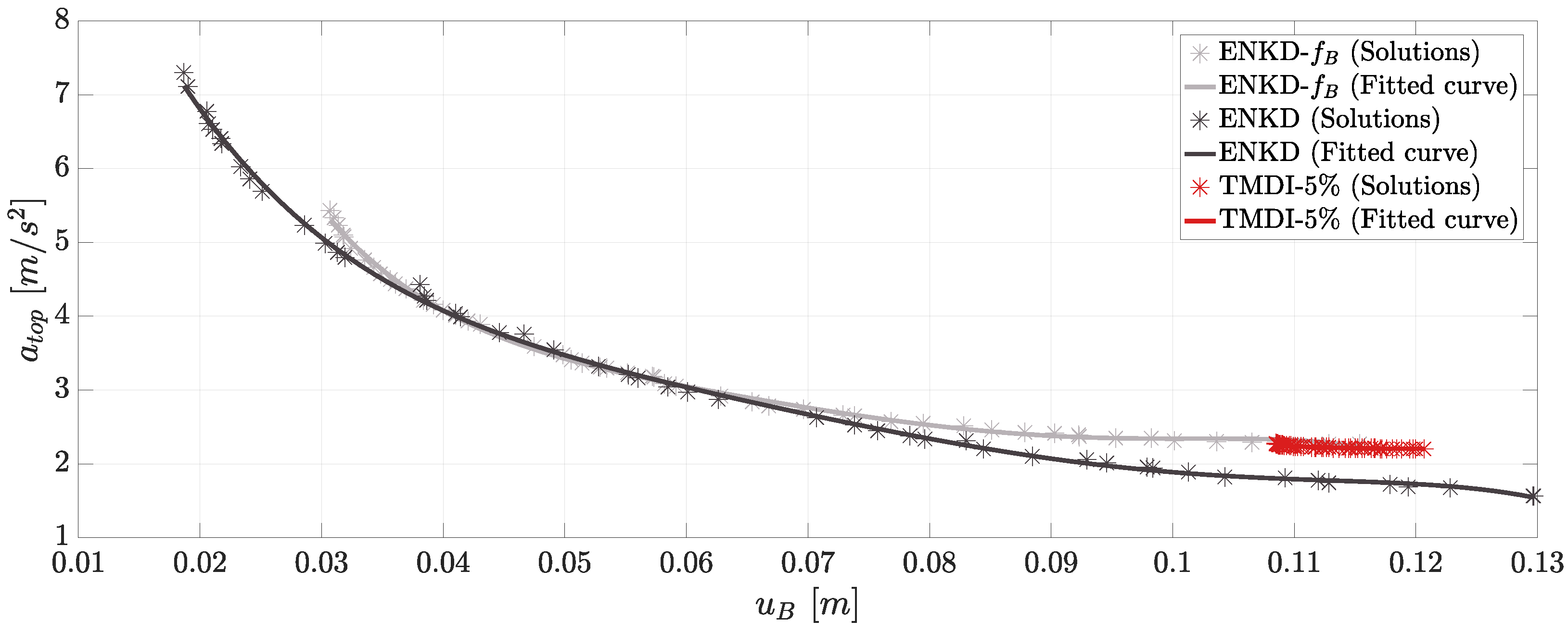
  • A stiffer approach of the ENKD that leads to considerably low values for base displacement at the cost of an increase in the acceleration of the top floor. From Figure 5, the optimal set of solutions is chosen, that results to objective function values of u B = 4.101 cm and a t o p = 4.031 m/s2. Hereafter, this system will be referred to as ENKD-S1 (Solution 1).
  • A more elastic approach of the ENKD that can retain the top floor acceleration below 2.5 m/s2, similar to the TMDI-5% VCS (Figure 5). However this results in higher values of base displacement. From the same figure, the optimal set of solutions is selected, that leads to objective function values of u B = 10.130 cm and a t o p = 1.884 m/s2. This system is denoted as ENKD-S2 (Solution 2).
The values of design variables of the ENKD-S1 and ENKD-S2 VCS are depicted in Table 2. From Equation (11), the values of stiffness k R and k P S elements can also be calculated. In Table 3, these values are given, along with the resulting objective functions as mentioned above.
According to Table 2 and Table 3, a stiffer approach of the ENKD leads to significantly higher values for the design variables k N S (in absolute terms), c N S , b R , b N S as well as the stiffness elements k R , k P S when compared to the elastic design approach. This may introduce more challenges in the realization and implementation of the ENKD-S1 device in the base of structures, which could also lead to economic feasibility issues. It is also important to note that in ENKD-S2 configuration, the value of c P S is approximately 20 times greater than c N S . This leads to the conclusion that for an elastic design approach, the c N S damper does not significantly impact the dynamic response of the building.
The selected KDamper-based VCS are compared with the TMDI-5% which, among the TMD-based VCS, was proven the most effective in reducing both the objective functions according to Section 4. The set of solutions that leads to the lowest obtained value of base displacement according to optimization is chosen (Figure 5). The values of the design variables, parameters and objective functions of this TMDI-5% system are summarized in Table 4.

5.3. Results of Dynamic Analysis

In this section, the results of the dynamic analysis are summarized. To provide a clearer assessment of the effectiveness of each examined VCS, the results of the ENKD-S1, ENKD-S2 and TMDI-5% systems are also compared to those of the initial base isolated structure without any supplemental control system (denoted as BI).
In Figure 6 and Figure 7, bar plots illustrate the values of u B and a t o p of each of the 10 real and 10 artificial accelerograms, respectively. These values correspond to the absolute maximum dynamic responses of the building during each excitation. According to Figure 6a and Figure 7a, the ENKD-S1 manages to drastically reduce the base displacement in all the examined records compared to BI and TMDI-5%. As expected, ENKD-S2 yields higher u B values. However, in 15 out of 20 analyses (9 from the real records and 6 from the artificial ones) these values are lower than those obtained from the TMDI-5% implementation. Furthermore, based on Figure 6b and Figure 7b, the ENKD-S2 also resulted in lower a t o p values than TMDI-5% in 8 out of 10 real record excitations and in 8 out of 10 artificial ones.
To facilitate a more straightforward comparison of the overall performance of the examined systems, Figure 8 is provided. In this figure, the u B and a t o p represent the mean absolute maximum dynamic responses of the building for each of the excitation groups (real and artificial accelerograms). The results are expressed as average ratios, with the subscript “BI” indicating the responses as emerged from the dynamic analysis of the initial base isolated building. According to this figure, the ENKD-S1 system manages to reduce by approximately 64.4% the u B , B I (on average from both excitation groups) and increase by 95.5% the a t o p , B I . However, the ENKD-S2 system reduces both u B , B I and a t o p , B I by 16.1% and 10.6% on average, respectively. As for the TMDI-5% configuration, it only achieves an average decrease of 9.9% in the value of u B , B I and it has a negligible impact on reducing the a t o p , B I (reduction below 0.3%).
Figure 9 and Figure 10 illustrate time history responses of the examined building for a specific real and artificial record, respectively. Figure 9a and Figure 10b depict the variation of the relative to the ground base displacement ( u B ) of the controlled building, while Figure 9b and Figure 10b the variation of the top floor acceleration over the duration of the seismic event. The real record used is the Northridge-N. Hollywood (No. 5 of Table 1) and the artificial accelerogram is one of the database with a PGA equal to 4.75 m/s2. These figures indicate that the ENKD-S2 system can reduce the dynamic responses of the BI throughout the time domain, not just in terms of peak values. The supplemental TMDI-5% slightly enhances the performance of the BI only in terms of u B , as the time histories of a t o p between TMDI-5% and BI systems are almost identical.

6. Conclusions

This paper examines the potential improvement in seismic performance of a base isolated (BI) 5-story building through the introduction of supplemental vibration control systems (VCS) at the isolation level. These systems are classified into two groups. The first group, referred to as KDamper-based VCS, comprises the KDamper, the Extended KDamper (EKD) and the EKD enhanced with inerters (ENKD). The second group, termed TMD-based VCS, includes Tuned Mass Damper (TMD) and Tuned Mass Damper Inerter (TMDI) devices with varying mass ratios. Devices with a mass ratio of 1% are referred to as TMD-1% and TMDI-1%, while those with a mass ratio of 5% are labeled as TMD-5% and TMDI-5%.
A multi-objective optimization of the 5-story building equipped with these VCS is formulated using the modified Non-Sorting Genetic Algorithm type II (NSGA-II) enhanced with the Crowding Distance Operator (CDO). The fixed parameters and design variables along with their limits, are determined based on engineering criteria. The objective functions are selected to be the base displacement and the top floor acceleration (in absolute maximum terms) of the examined control building under 30 artificial accelerograms. One additional group of KDamper-based VCS is also optimized with a value of nominal frequency equal to the one according to which the TMD-based VCS were tuned (frequency f B of the base isolated building). To determine which VCS is more capable of minimizing both objective functions, a comparison of their generated Pareto fronts is performed.
Furthermore, a numerical case study is conducted to assess the performance of the TMDI-5% and the ENKD in terms of reducing the dynamic responses of the 5-story base isolated building. The design values of each system are selected among the optimal solutions sets as emerged from optimization. For the ENKD, two solutions are selected: a stiff approach, labeled as ENKD-S1 and a more elastic one, referred to as ENKD-S2. A group of 10 real records along with 10 artificial accelerograms are selected as excitation inputs for the dynamic analysis of the 5-story building equipped with the examined systems.
Based on the optimization results and the outcomes of the numerical case study, the following summarized conclusions can be made:
i.
The design of the proposed base isolation VCS supplements is realistic, as it accounts for variations in the values of all installed stiffness elements, thus, ensuring the static and dynamic stability of the controlled BI structure.
ii.
Among the KDamper-based VCS, the ENKD is the most effective one. For values of base displacement lower than approximately 9 cm (according to optimization results), it has the potential of reducing the acceleration of the top floor more compared to the other systems of the same group.
iii.
The generated Pareto fronts of the EKD and ENKD systems for a base displacement range between 4 cm and 6 cm are almost identical to those of the EKD and ENKD systems with a nominal frequency of f B .
iv.
According to the optimization results, the TMDI-5% is the best performing system among the other TMD-based VCS. However, it is limited to base displacements in the range of 10.8–12 cm. In comparison, the KDamper VCS offer a much wider range of solutions and can provide alternative BI designs with “stiffer” base frequencies.
v.
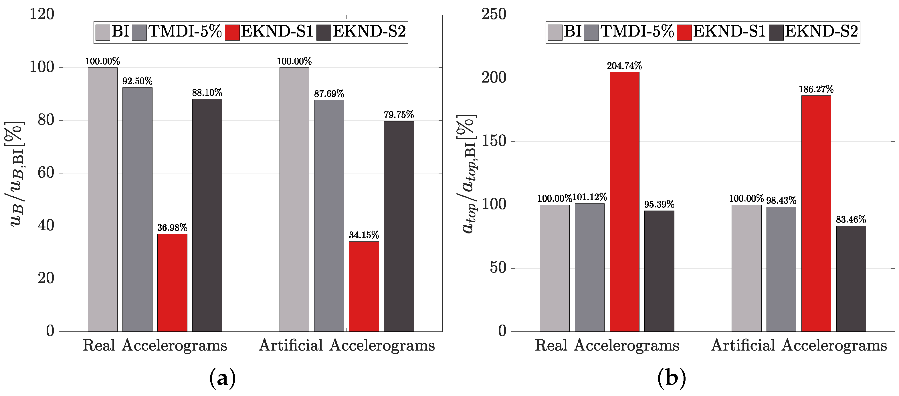
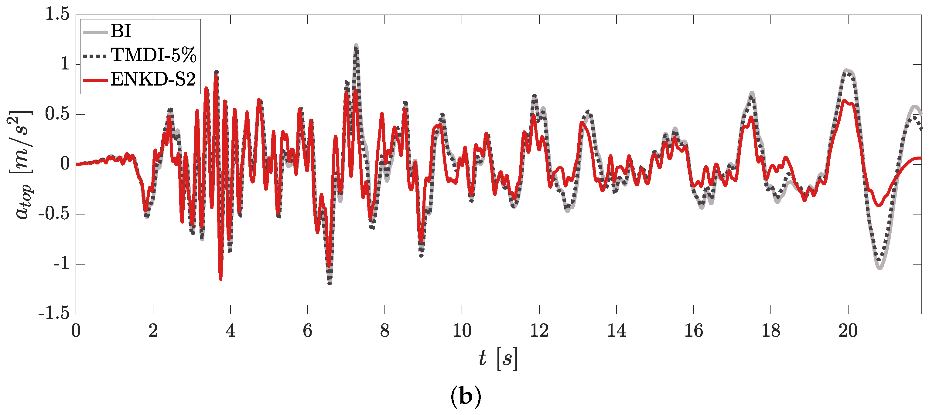
Based on the numerical case study, the ENKD-S1 system manages to reduce the average absolute maximum base displacement of the building by approximately 64.4% at the cost of increasing the average absolute maximum acceleration of the top floor (95.5% increase). However, the ENKD-S2 system reduces both the base displacement and the top floor acceleration by 16.1% and 10.6%, respectively. The TMDI-5% decreases the displacement of the base by approximately 9.9%, but has a negligible impact on reducing the top floor acceleration (reduction below 0.3%) of the building. Therefore, the ENKD-S2 manages to outperform the TMDI-5%, employing only the 1/50 of the additional mass of the later.
Based on the results of this work, the following directions for future research are suggested:
i.
The study of the practical implementation challenges, considerations and economic factors associated with integrating the proposed KDamper-based VCS in real-world construction scenarios.
ii.
The realistic design of the proposed devices including detailed presentations of their NS mechanisms and the selection/design of their elements based on existing commercial and design catalogs.
iii.
The integration of the KDamper-based VCS to highly damped base isolated structures, taking into account their complex hysteretic behavior.
iv.
The extension of this work to the case of 3D base isolated structures.
v.
The comparison of the KDamper-based VCS (which are categorized as passive seismic base isolation devices) with other semi-active or active VCS.
vi.
The implementation of the examined optimization framework and the proposed devices to various types of structures (including bridges and wind-turbines), subjected to different levels of seismic intensity.

Author Contributions

Conceptualization, G.F. and K.K.; methodology, G.F. and K.K.; software, G.F.; validation, G.F. and K.K.; formal analysis, G.F. and K.K.; investigation, G.F. and K.K.; resources, G.F. and K.K.; data curation, G.F. and K.K.; writing—original draft preparation, G.F. and K.K.; writing—review and editing, G.F. and K.K.; visualization, G.F. and K.K.; supervision, E.S.; project administration, E.S.; funding acquisition, E.S. All authors have read and agreed to the published version of the manuscript.

Funding

This research received no external funding.

Data Availability Statement

The data that support the findings of this study are available from the corresponding author, Georgios Florakis, upon request.

Acknowledgments

Georgios Florakis would like to acknowledge the financial support by the Special Account for Research Funding (E.L.K.E) of National Technical University of Athens (N.T.U.A) for Doctoral (PhD) studies. Konstantinos Kapasakalis would like to acknowledge the support by the Bodossaki Foundation—Scholarship for Postdoctoral studies.

Conflicts of Interest

The authors declare no conflict of interest.

Abbreviations

The following abbreviations are used in this manuscript:
VCSVibration Control Systems (or System)
BIBase Isolation or Base Isolated structure
NSNegative Stiffness
PSPositive Stiffness
TMDTuned Mass Damper
TMDITuned Mass Damper Inerter
EKDExtended KDamper
SBASeismic Base Absorber
ENKDExtended KDamper enhanced with inerters
NSGA-IINon-Sorting Genetic Algorithm Type-II
CDOCrowding Distance Operator
OFObjective Function
RCReinforced Concrete
EC8Eurocode 8
PGAPeak Ground Acceleration
PGDPeak Ground Displacement

Appendix A

The equations of motion of the controlled base isolated structure with the examined VCS are presented in Equation (4). The matrices of mass, stiffness, and damping can be expressed to include any examined VCS as follows:
M V C S ( n + 2 ) × ( n + 2 ) = M S T R n × n 0 n × 1 0 n × 1 0 1 × n m B B m B V C S 0 1 × n m V C S B m V C S V C S
K V C S ( n + 2 ) × ( n + 2 ) = K S T R n × n 0 n × 1 0 n × 1 0 1 × n k B B k B V C S 0 1 × n k V C S B k V C S V C S
C V C S ( n + 2 ) × ( n + 2 ) = C S T R n × n 0 n × 1 0 n × 1 0 1 × n c B B c B V C S 0 1 × n c V C S B c V C S V C S
M V C S ( n + 2 ) × ( n + 2 ) ( e f f ) = M S T R n × n 0 n × 1 0 n × 1 0 1 × n m B B ( e f f ) m B V C S ( e f f ) 0 1 × n m V C S B ( e f f ) m V C S V C S ( e f f )

Appendix A.1. TMD-Based VCS

In the case where a TMD is implemented at the base level, the components of the matrices presented in Equation (A1) are defined as:
m B B = m B
m B V C S = m V C S B = 0
m V C S V C S = m T M D
c B B = c B
c B V C S = c V C S B = c T M D
c V C S V C S = c T M D
k B B = k B
k B V C S = k V C S B = k T M D
k V C S V C S = k T M D
m B B ( e f f ) = m B
m B V C S ( e f f ) = m V C S B ( e f f ) = 0
m V C S V C S ( e f f ) = m T M D
With the inclusion of the inerter in the TMD configuration (TMDI VCS), Equation (A6) are modified as:
m B B = m B
m B V C S = m V C S B = 0
m V C S V C S = m T M D I + b T M D I M t o t

Appendix A.2. KDamper-Based VCS

With the introduction of the KDamper as a supplement to the isolation base, the elements of the matrices in Equation (A1) are the following:
m B B = m B
m B V C S = m V C S B = 0
m V C S V C S = m K D
c B B = c B + c P S
c B V C S = c V C S B = c P S
c V C S V C S = c P S
k B B = k B + k R + k P S
k B V C S = k V C S B = k P S
k V C S V C S = k P S + k N S
m B B ( e f f ) = m B
m B V C S ( e f f ) = m V C S B ( e f f ) = 0
m V C S V C S ( e f f ) = m K D
Employing the extended version of the KDamper (EKD VCS), the mass components (Equations (A7) and (A10)) remain the same with the KDamper case, while the stiffness and damping related elements of Equation (A1) are modified as:
c B B = c B + c N S
c B V C S = c V C S B = c N S
c V C S V C S = c N S + c P S
k B B = k B + k R + k N S
k B V C S = k V C S B = k N S
k V C S V C S = k P S + k N S
With the enhanced EKD with inerter elements (ENKD VCS) the stiffness, damping, and effective mass components (Equations (A10)–(A12)) remain the same with the EKD case, while the mass elements of Equation (A1) are modified as:
m B B = m B + b R M t o t + b N S M t o t
m B V C S = m V C S B = b N S M t o t
m V C S V C S = m K D + b N S M t o t

References

  1. Castaldo, P. Passive Structural Control. In Integrated Seismic Design of Structure and Control Systems; Springer International Publishing: Cham, Switzerland, 2014; pp. 1–19. [Google Scholar] [CrossRef]
  2. Soong, T.T.; Costantinou, M.C. Passive and Active Structural Vibration Control in Civil Engineering; Springer: Berlin/Heidelberg, Germany, 2014; Volume 345. [Google Scholar]
  3. De Iuliis, M.; Castaldo, P. An energy-based approach to the seismic control of one-way asymmetrical structural systems using semi-active devices. Ing. Sismica 2012, 29, 31–50. [Google Scholar]
  4. Makris, N. Seismic isolation: Early history. Earthq. Eng. Struct. Dyn. 2019, 48, 269–283. [Google Scholar] [CrossRef]
  5. Chen, M.; Pantoli, E.; Wang, X.; Espino, E.; Mintz, S.; Conte, J.; Hutchinson, T.; Marin, C.; Meacham, B.; Restrepo, J.; et al. Design and Construction of a Full-Scale 5-Story Base Isolated Building Outfitted with Nonstructural Components for Earthquake Testing at the UCSD-NEES Facility. In Structures Congress 2012; American Society of Civil Engineers (ASCE): Reston, VA, USA, 2012; pp. 1349–1360. [Google Scholar] [CrossRef]
  6. Sanchez, J.; Masroor, A.; Mosqueda, G.; Ryan, K. Static and Dynamic Stability of Elastomeric Bearings for Seismic Protection of Structures. J. Struct. Eng. 2013, 139, 1149–1159. [Google Scholar] [CrossRef]
  7. Yang, T.Y.; Zhang, H. Seismic Safety Assessment of Base-Isolated Buildings Using Lead-Rubber Bearings. Earthq. Spectra 2019, 35, 1087–1108. [Google Scholar] [CrossRef]
  8. De Domenico, D.; Losanno, D.; Vaiana, N. Experimental tests and numerical modeling of full-scale unbonded fiber reinforced elastomeric isolators (UFREIs) under bidirectional excitation. Eng. Struct. 2023, 274, 115118. [Google Scholar] [CrossRef]
  9. Kalpakidis, I. Lead-Rubber Bearings with Emphasis on Their Implementation to Structural Design. In Encyclopedia of Earthquake Engineering; Springer: Berlin/Heidelberg, Germany, 2014; pp. 1–11. [Google Scholar] [CrossRef]
  10. Ravari, A.K.; Othman, I.B.; Ibrahim, Z.B.; Ab-Malek, K. P-Δ and End Rotation Effects on the Influence of Mechanical Properties of Elastomeric Isolation Bearings. J. Struct. Eng. 2012, 138, 669–675. [Google Scholar] [CrossRef]
  11. Javidan, M.M.; Naeem, A.; Kim, J. Seismic retrofit of structures using added steel column friction dampers. Steel Compos. Struct. 2023, 49, 257–270. [Google Scholar] [CrossRef]
  12. Dereje, A.J.; Javidan, M.M.; Ahn, T.S.; Kim, J. Experimental and analytical study of a seismic energy dissipation device made of butterfly-shaped steel plates and viscoelastic pads. J. Build. Eng. 2024, 82, 108251. [Google Scholar] [CrossRef]
  13. Javidana, M.M.; Kim, J. Steel hexagonal damper-brace system for efficient seismic protection of structures. Steel Compos. Struct. 2022, 45, 683–695. [Google Scholar] [CrossRef]
  14. Javidan, M.M.; Kim, J. A ductile steel damper-brace for low-damage framed structures. Steel Compos. Struct. 2022, 44, 325–337. [Google Scholar] [CrossRef]
  15. Tsai, H.C. The effect of tuned-mass dampers on the seismic response of base-isolated structures. Int. J. Solids Struct. 1995, 32, 1195–1210. [Google Scholar] [CrossRef]
  16. Taniguchi, T.; Der Kiureghian, A.; Melkumyan, M. Effect of tuned mass damper on displacement demand of base-isolated structures. Eng. Struct. 2008, 30, 3478–3488. [Google Scholar] [CrossRef]
  17. Palazzo, B.; Petti, L. Combined control strategy: Base isolation and tuned mass damping. ISET J. Earthq. Technol. 1999, 36, 121–137. [Google Scholar]
  18. Stanikzai, M.H.; Elias, S.; Matsagar, V.A.; Jain, A.K. Seismic response control of base-isolated buildings using tuned mass damper. Aust. J. Struct. Eng. 2020, 21, 310–321. [Google Scholar] [CrossRef]
  19. Xiang, P.; Nishitani, A. Optimum design for more effective tuned mass damper system and its application to base-isolated buildings. Struct. Control Health Monit. 2014, 21, 98–114. [Google Scholar] [CrossRef]
  20. Weber, B.; Feltrin, G. Assessment of long-term behavior of tuned mass dampers by system identification. Eng. Struct. 2010, 32, 3670–3682. [Google Scholar] [CrossRef]
  21. Kang, Y.-j.; Peng, L.-y. Optimisation Design and Damping Effect Analysis of Large Mass Ratio Tuned Mass Dampers. Shock Vib. 2019, 2019, 8376781. [Google Scholar] [CrossRef]
  22. Smith, M.C. Synthesis of Mechanical Networks: The Inerter. IEEE Trans. Autom. Control 2002, 47, 1648–1662. [Google Scholar] [CrossRef]
  23. Lazar, I.F.; Neild, S.A.; Wagg, D.J. Using an inerter-based device for structural vibration suppression. Earthq. Eng. Struct. Dyn. 2014, 43, 1129–1147. [Google Scholar] [CrossRef]
  24. Pietrosanti, D.; De Angelis, M.; Basili, M. Optimal design and performance evaluation of systems with Tuned Mass Damper Inerter (TMDI). Earthq. Eng. Struct. Dyn. 2017, 46, 1367–1388. [Google Scholar] [CrossRef]
  25. Giaralis, A.; Taflanidis, A.A. Optimal tuned mass-damper-inerter (TMDI) design for seismically excited MDOF structures with model uncertainties based on reliability criteria. Struct. Control Health Monit. 2018, 25, e2082. [Google Scholar] [CrossRef]
  26. De Domenico, D.; Ricciardi, G. An enhanced base isolation system equipped with optimal tuned mass damper inerter (TMDI). Earthq. Eng. Struct. Dyn. 2018, 47, 1169–1192. [Google Scholar] [CrossRef]
  27. De Domenico, D.; Impollonia, N.; Ricciardi, G. Soil-dependent optimum design of a new passive vibration control system combining seismic base isolation with tuned inerter damper. Soil Dyn. Earthq. Eng. 2018, 105, 37–53. [Google Scholar] [CrossRef]
  28. De Angelis, M.; Giaralis, A.; Petrini, F.; Pietrosanti, D. Optimal tuning and assessment of inertial dampers with grounded inerter for vibration control of seismically excited base-isolated systems. Eng. Struct. 2019, 196, 109250. [Google Scholar] [CrossRef]
  29. Ahmet Hilmi Deringöl, E.M.G. Effect of Using High Damping Rubber Bearings for Seismic Isolation of the Buildings. Int. J. Steel Struct. 2021, 21, 1698–1722. [Google Scholar] [CrossRef]
  30. Dai, K.; Yang, Y.; Li, T.; Ge, Q.; Wang, J.; Wang, B.; Chen, P.; Huang, Z. Seismic analysis of a base-isolated reinforced concrete frame using high damping rubber bearings considering hardening characteristics and bidirectional coupling effect. Structures 2022, 46, 698–712. [Google Scholar] [CrossRef]
  31. Platus, D.L. Negative-Stiffness-Mechanism Vibration Isolation Systems. In Proceedings of the SPIE Technical: OPTCON ’91, San Jose, CA, USA, 1–30 November 1992; Volume 1619, pp. 44–54. [Google Scholar]
  32. Antoniadis, I.; Chronopoulos, D.; Spitas, V.; Koulocheris, D. Hyper-damping properties of a stiff and stable linear oscillator with a negative stiffness element. J. Sound Vib. 2015, 346, 37–52. [Google Scholar] [CrossRef]
  33. Iemura, H.; Pradono, M.H. Advances in the development of pseudo-negative-stiffness dampers for seismic response control. Struct. Control Health Monit. 2009, 16, 784–799. [Google Scholar] [CrossRef]
  34. Sarlis, A.A.; Pasala, D.T.R.; Constantinou, M.C.; Reinhorn, A.M.; Nagarajaiah, S.; Taylor, D.P. Negative Stiffness Device for Seismic Protection of Structures. J. Struct. Eng. 2012, 139, 1124–1133. [Google Scholar] [CrossRef]
  35. Pasala, D.T.R.; Sarlis, A.A.; Nagarajaiah, S.; Reinhorn, A.M.; Constantinou, M.C.; Taylor, D. Adaptive Negative Stiffness: New Structural Modification Approach for Seismic Protection. J. Struct. Eng. 2013, 139, 1112–1123. [Google Scholar] [CrossRef]
  36. Attary, N.; Symans, M.; Nagarajaiah, S. Development of a rotation-based negative stiffness device for seismic protection of structures. J. Vib. Control 2017, 23, 853–867. [Google Scholar] [CrossRef]
  37. Saha, A.; Mishra, S.K. Adaptive Negative Stiffness Device based nonconventional Tuned Mass Damper for seismic vibration control of tall buildings. Soil Dyn. Earthq. Eng. 2019, 126, 105767. [Google Scholar] [CrossRef]
  38. Sarlis, A.A.; Pasala, D.T.R.; Constantinou, M.C.; Reinhorn, A.M.; Nagarajaiah, S.; Taylor, D.P. Negative Stiffness Device for Seismic Protection of Structures: Shake Table Testing of a Seismically Isolated Structure. J. Struct. Eng. 2016, 142, 04016005. [Google Scholar] [CrossRef]
  39. Wang, M.; Sun, F.-f.; Jin, H.-j. Performance evaluation of existing isolated buildings with supplemental passive pseudo-negative stiffness devices. Eng. Struct. 2018, 177, 30–46. [Google Scholar] [CrossRef]
  40. Li, H.N.; Sun, T.; Lai, Z.; Nagarajaiah, S. Effectiveness of Negative Stiffness System in the Benchmark Structural-Control Problem for Seismically Excited Highway Bridges. J. Bridge Eng. 2018, 23, 04018001. [Google Scholar] [CrossRef]
  41. Cimellaro, G.P.; Domaneschi, M.; Warn, G. Three-Dimensional Base Isolation Using Vertical Negative Stiffness Devices. J. Earthq. Eng. 2018, 24, 2004–2032. [Google Scholar] [CrossRef]
  42. Zhao, Z.; Wang, Y.; Hu, X.; Weng, D. Seismic performance upgrading of containment structures using a negative-stiffness amplification system. Eng. Struct. 2022, 262, 114394. [Google Scholar] [CrossRef]
  43. Antoniadis, I.A.; Kanarachos, S.A.; Gryllias, K.; Sapountzakis, I.E. KDamping: A stiffness based vibration absorption concept. JVC/J. Vib. Control 2018, 24, 588–606. [Google Scholar] [CrossRef]
  44. Kapasakalis, K.; Antoniadis, I.; Sapountzakis, E. Performance assessment of the KDamper as a seismic Absorption Base. Struct. Control Health Monit. 2020, 27, e2482. [Google Scholar] [CrossRef]
  45. Sapountzakis, E.J.; Syrimi, P.G.; Pantazis, I.A.; Antoniadis, I.A. KDamper concept in seismic isolation of bridges with flexible piers. Eng. Struct. 2017, 153, 525–539. [Google Scholar] [CrossRef]
  46. Kapasakalis, K.; Antoniadis, I.; Sapountzakis, E. Constrained optimal design of seismic base absorbers based on an extended KDamper concept. Eng. Struct. 2021, 226, 111312. [Google Scholar] [CrossRef]
  47. Mantakas, A.G.; Kapasakalis, K.A.; Alvertos, A.E.; Antoniadis, I.A.; Sapountzakis, E.J. A negative stiffness dynamic base absorber for seismic retrofitting of residential buildings. Struct. Control Health Monit. 2022, 29, e3127. [Google Scholar] [CrossRef]
  48. Kapasakalis, K.; Mantakas, A.; Kalderon, M.; Antoniou, M.; Sapountzakis, E. Performance Evaluation of Distributed Extended KDamper Devices for Seismic Protection of Mid-Rise Building Structures. J. Earthq. Eng. 2023, 28, 972–997. [Google Scholar] [CrossRef]
  49. Florakis, G.; Kapasakalis, K.; Antoniadis, I.; Sapountzakis, E. Dimensioning and realistic design of a novel based negative stiffness seismic isolator. In Proceedings of the XII International Conference in Structural Dynamics (EURODYN), Southampton, UK, 1–3 July 2023. [Google Scholar]
  50. Kapasakalis, K.A.; Antoniadis, I.A.; Sapountzakis, E.J. STIFF vertical seismic absorbers. J. Vib. Control 2022, 28, 1937–1949. [Google Scholar] [CrossRef]
  51. Kalogerakou, M.E.; Kapasakalis, K.A.; Antoniadis, I.A.; Sapountzakis, E.J. Vertical seismic protection of structures with inerter-based negative stiffness absorbers. Bull. Earthq. Eng. 2022, 21, 1439–1480. [Google Scholar] [CrossRef]
  52. Gkikakis, A.E.; Kapasakalis, K.A.; Sapountzakis, E.J. Comprehensive design optimization of vertical seismic absorbers incorporating sensitivity and robust analysis: A case study of the KDamper. Eng. Struct. 2024, 301, 117303. [Google Scholar] [CrossRef]
  53. Kampitsis, A.; Kapasakalis, K.; Via-Estrem, L. An integrated FEA-CFD simulation of offshore wind turbines with vibration control systems. Eng. Struct. 2022, 254, 113859. [Google Scholar] [CrossRef]
  54. Kapasakalis, K.A.; Antoniadis, I.A.; Sapountzakis, E.J.; Kampitsis, A.E. Vibration Mitigation of Wind Turbine Towers Using Negative Stiffness Absorbers. J. Civ. Eng. Constr. 2021, 10, 123–139. [Google Scholar] [CrossRef]
  55. Kapasakalis, K.; Antoniadis, I.; Sapountzakis, E. Feasibility Assessment of Stiff Seismic Base Absorbers. J. Vib. Eng. Technol. 2021, 10, 37–53. [Google Scholar] [CrossRef]
  56. Kapasakalis, K.; Florakis, G.; Antoniadis, I.; Sapountzakis, E. Seismic Protection of Multi-Story Structures with Novel Vibration Absorption Devices Combining Negative Stiffness and Inerter. In Proceedings of the 8th International Conference on Computational Methods in Structural Dynamics and Earthquake Engineering, Athens, Greece, 28–30 June 2021; pp. 4026–4045. [Google Scholar] [CrossRef]
  57. Florakis, G.I.; Antoniadis, I.A.; Sapountzakis, E.J. A novel gas spring based negative stiffness mechanism for seismic protection of structures. Eng. Struct. 2023, 291, 116389. [Google Scholar] [CrossRef]
  58. Florakis, G.; Kapasakalis, K.; Sapountzakis, E.; Antoniadis, I. Multi-Objective Optimization of a Seismic Base Absorber Incorporating Negative Stiffness. In Proceedings of the 29th International Congress on Sound and Vibration, Prague, Czech Republic, 9–13 July 2023. [Google Scholar]
  59. Vaiana, N.; Rosati, L. Analytical and differential reformulations of the Vaiana–Rosati model for complex rate-independent mechanical hysteresis phenomena. Mech. Syst. Signal Process. 2023, 199, 110448. [Google Scholar] [CrossRef]
  60. Vaiana, N.; Rosati, L. Classification and unified phenomenological modeling of complex uniaxial rate-independent hysteretic responses. Mech. Syst. Signal Process. 2023, 182, 109539. [Google Scholar] [CrossRef]
  61. Li, H.; Yu, Y.; Li, J.; Li, Y.; Askari, M. Multi-objective optimisation for improving the seismic protection performance of a multi-storey adaptive negative stiffness system based on modified NSGA-II with DCD. J. Build. Eng. 2021, 43, 103145. [Google Scholar] [CrossRef]
  62. Heris, M.K. NSGA-II in MATLAB. Yarpiz. 2015. Available online: https://yarpiz.com/56/ypea120-nsga2 (accessed on 10 April 2023).
  63. Etedali, S.; Rakhshani, H. Optimum design of tuned mass dampers using multi-objective cuckoo search for buildings under seismic excitations. Alex. Eng. J. 2018, 57, 3205–3218. [Google Scholar] [CrossRef]
  64. Seismosoft. SeismoArtif—A Computer Program for Generating Artificial Earthquake Accelerograms Matched to a Specific Target Response Spectrum; Seismosoft: Pavia, Italy, 2018. [Google Scholar]
  65. Den Hartog, J.P. Mechanical Vibrations, 4th ed.; McGraw-Hill Book Co., Inc.: New York, NY, USA; London, UK, 1956. [Google Scholar] [CrossRef]
  66. Pacific Earthquake Engineering Research Center-Ground Motion Database. Available online: https://ngawest2.berkeley.edu/ (accessed on 20 January 2023).
Figure 1. Schematic representation of a multi-story base isolated building structure supplemented with VCS, and VCS configurations: (i) KDamper, (ii) EKD, (iii) ENKD, (iv) TMD, and (v) TMDI.
Buildings 14 00955 g001
Figure 2. Representation of the (a) 3D model and the (b) floor plan of the examined 5-story building without base isolation.
Buildings 14 00955 g002
Figure 3. Pareto fronts of the 5-story building equipped with supplemental: (a) KDamper-based VCS and (b) TMD-based VCS.
Buildings 14 00955 g003
Figure 4. Comparative Pareto fronts of the: (a) KDamper-based VCS with nominal frequency f B and the (b) KDamper, (c) EKD, (d) ENKD systems with nominal frequencies f B and f B K D , as obtained from the multi-objective optimization of the 5-story building.
Buildings 14 00955 g004aBuildings 14 00955 g004b
Figure 5. Comparative Pareto fronts of the base isolated 5-story building equipped with the ENKD systems with nominal frequencies of f B and f B K D and the TMDI with a mass ratio of 5 % .
Buildings 14 00955 g005
Figure 6. Resulting values of (a) u B and (b) a t o p of the 5-story building for each real record. Comparison among the BI, TMDI-5%, ENKD-S1 and ENKD-S2 systems.
Buildings 14 00955 g006
Figure 7. Resulting values of (a) u B and (b) a t o p of the 5-story building for each artificial record. Comparison among the BI, TMDI-5%, ENKD-S1 and ENKD-S2 systems.
Buildings 14 00955 g007
Figure 8. Average ratios (a) u B / u B , B I and (b) a t o p / a t o p , B I , from all the real and artificial records. Comparison among the BI, TMDI-5%, ENKD-S1 and ENKD-S2 systems.
Buildings 14 00955 g008
Figure 9. Time history responses of the (a) relative to the ground base displacement ( u B ) and the (b) acceleration of the top floor ( a t o p ) of the 5-story building during the Northridge-N. Hollywood seismic event. Comparison among the BI, TMDI-5% and ENKD-S2 systems.
Buildings 14 00955 g009aBuildings 14 00955 g009b
Figure 10. Time history responses of the (a) relative to the ground base displacement ( u B ) and the (b) acceleration of the top floor ( a t o p ) of the 5-story building during an artificial accelerogram. Comparison among the BI, TMDI-5% and ENKD-S2 systems.
Buildings 14 00955 g010
Table 1. Information and characteristics of the chosen near-fault earthquake records.
NoEarthquakeYearRecordingMwPGAPGDRJBDur5–95%
Name Station [g] [cm] [km] [s]
1Friuli1976Tolmezzo6.50.35714.58814.974.9
2Kocaeli1999Izmit7.510.165111.8363.6215.1
3Chi-Chi1999CHY0067.620.358716.9949.7626.7
4Landers1992Joshua tree7.280.27367.70411.0327.1
5Northridge1994N. Hollywood6.690.30879.0237.8916.0
6Kobe1995Amagasaki6.90.275826.59311.3419.4
7Duzce1999Lamont 10597.140.152410.1904.1715.0
8Niigata2004NIG0176.630.476512.7584.2236.7
9Kozani1995Kozani6.40.20691.74714.138.6
10L’Aquila2009V. Aterno6.30.40185.2680.07.6
Table 2. Values of the design variables from the selected ENKD VCS.
VCSDesign Variables
f 0 k NS c NS c PS b R b NS
[Hz] [kN/m] [kNs/m] [kNs/m] [%] [%]
ENKD-S10.613−82,383.625591.838417.2315.357.40
ENKD-S20.321−43,989.97515.0510,071.562.311.14
Table 3. Resulting values of stiffness elements and objective functions from the selected ENKD VCS.
VCSResulting StiffnessObjective Functions
k R k PS u B a top
[kN/m] [kN/m] [cm] [m/s2]
ENKD-S1155,652.54180,509.824.1014.031
ENKD-S244,416.86147,592.8110.1301.884
Table 4. Values of the selected TMDI-5% VCS and the resulting objective functions.
Design VariablesResulting ParametersObjective Functions
t TMD ζ TMD b TMDI f TMD k TMD c TMD u B a top
[Hz] [%] [%] [Hz] [kN/m] [kNs/m] [cm] [m/s2]
1.14149.0414.290.6521736.80415.8310.8482.278
Disclaimer/Publisher’s Note: The statements, opinions and data contained in all publications are solely those of the individual author(s) and contributor(s) and not of MDPI and/or the editor(s). MDPI and/or the editor(s) disclaim responsibility for any injury to people or property resulting from any ideas, methods, instructions or products referred to in the content.

