Article

Effect of Precursor Blending Ratio and Rotation Speed of Mechanically Activated Fly Ash on Properties of Geopolymer Foam Concrete

1
School of Civil Engineering and National-Local Joint Engineering Laboratory of Building Health Monitoring and Disaster Prevention Technology, Anhui Jianzhu University, Anhui 230601, China
2
Research Institute of Interdisciplinary Sciences (RISE) and School of Materials Science & Engineering, Dongguan University of Technology, Dongguan 523808, China
*
Author to whom correspondence should be addressed.
Buildings 2024, 14(3), 841; https://doi.org/10.3390/buildings14030841
Submission received: 30 January 2024 / Revised: 14 March 2024 / Accepted: 15 March 2024 / Published: 20 March 2024

Abstract

:
This research used fly ash and slag to create geopolymer foam concrete. They were activated with an alkali, resulting in a chemical reaction that produced a gel that strengthened the concrete’s structural integrity. The experimental approach involved varying the fly ash content in the precursors at incremental percentages (10%, 30%, 50%, 70% and 90%) and subjecting the fly ash to mechanical activation through a planetary ball mill at distinct rotational speeds (380, 400, 420 and 440 rpm). The investigation discerned that the fly ash content and particle structure exert a discernible influence on macroscopic properties, including flowability, air generation height, compressive strength, dry density and microstructural characteristics such as pore distribution and hydration product arrangement in the geopolymer foam concrete. Employing analytical techniques such as X-ray diffraction (XRD) and scanning electron microscopy (SEM), it was deduced that diminishing the fly ash content correlates with an enhancement in compressive strength. Furthermore, the specific strength of the geopolymer foam concrete reached a peak of 0.041 when the activated fly ash in the planetary ball mill rotated at 420 rpm, manifesting a lightweight and high-strength outcome.

1. Introduction

Concrete stands as a ubiquitous construction material on a global scale, wherein Portland cement assumes a pivotal role. However, the prevalent methods of its production and application engender a considerable carbon footprint, exacerbating the erosion of the Earth’s ecology through the emission of greenhouse gases [1,2]. This phenomenon poses an imminent threat to the environment, underscoring the imperative need for sustainable alternatives. Statistical data reveal that the production of Portland cement alone contributes to approximately 7% to 8% of the world’s greenhouse gas emissions, thus magnifying its substantial impact on climate change [3,4]. The cement industry, therefore, emerges as a formidable obstacle in the collective endeavor to achieve carbon peak and carbon neutrality, necessitating innovative solutions to address these unprecedented challenges [5,6]. Geopolymer concrete, commonly referred to as GPC, distinguishes itself by boasting low carbon content and negligible greenhouse gas emissions. This characteristic positions it as a viable substitute for conventional Portland-cement-based concrete, marking a significant stride toward adopting environmentally sustainable construction materials. The emergence of geopolymer concrete heralds a promising era wherein the construction industry can embrace an eco-friendly alternative, contributing to the reduction in its overall environmental impact [7,8]. Davidovits et al. [9]. introduced the term “geopolymer” to designate the amorphous alkali aluminate gel in his proposal. This nomenclature has since become integral to the classification and understanding of this specific type of material in the field. This innovative material is garnering attention as an environmentally friendly solution, primarily owing to its substantial reduction in carbon emissions when juxtaposed with conventional Portland-cement-based concrete [6,10].
Foamed concrete, crafted from a blend of fly ash (FA) and ground granulated blast furnace slag (GGBS), represents a recently developed geopolymer material notable for its exceptional insulation properties in terms of both heat and sound [11,12,13,14]. More specifically, its energy-efficient performance sets it apart from conventional cement-based foam concrete [10,15]. Furthermore, the material’s diminished energy consumption and improved economic viability enhance its overall appeal [16]. The combination of fly ash (FA) and ground granulated blast furnace slag (GGBS), facilitated by alkali activation, yields robust geopolymer concrete, thereby leading to favorable mechanical properties [17,18]. The introduction of aluminum powder into the alkali-activated geopolymer mixture induces the formation of pores in the slurry, giving rise to porous bodies that demonstrate outstanding thermal insulation properties, among other benefits [19,20,21]. The size, shape, crystallinity and particle size of fly ash (FA) collectively exert a substantial influence on the hydration reaction and microstructure formation in geopolymer concrete. Elevating the amorphous fly ash content enhances its reactivity. The reduction in particle size contributes to an increased specific surface area of SiO2, facilitating comprehensive interaction between fly ash and the activator. This, in turn, accelerates precipitation and reaction rates. Moreover, the diminution in particle size can impact the pore structure and overall porosity of the resulting slurry [22,23].
The distinctive characteristics of geopolymer foam concrete (GFC) arise from the dissolution of aluminum (Al) and silicon (Si) components in the precursor material, facilitated by the alkali activator abundant in hydroxide ions (OH) and catalyzed by the alkali activator. After this dissolution, depolymerization occurs, resulting in the formation of negatively charged silicate and aluminate species. In the polycondensation phase, cations such as Na+ and Ca2+ are introduced, which leads to the development of a geopolymer structure. Finally, the process culminates in the C-S-H, C-A-S-H and N-A-S-H gel, contributing to the overall composition and characteristics of GFC [24,25]. Research findings suggest that the presence of Ca2+ influences the formation of hydration products in geopolymers, resulting in diverse structures of hydration products in alkali-activated geopolymers under varying concentrations of Ca2+. This variation, in turn, has a consequential effect on the mechanical strength of the geopolymers [26,27]. The performance of GFC is significantly influenced by the properties and composition of precursor components. The proportion of FA to GGBS is a critical determinant of the GFC composition, thus influencing its overall performance from varied precursor systems. M.X. Fan et al. [28] proposed that the levels of calcium oxide (CaO) and silicon dioxide (SiO2) in the precursor impact the workability and strength of the concrete. Optimal CaO and SiO2 contents are suggested to result in enhanced machinability and superior mechanical properties. Mo Zhang et al. [29] employed a hybrid model comprising a random forest and genetic algorithm, revealing that the precursor Ca/Si and Al/Si ratios significantly influence the uniaxial compressive strength of GPC. Owing to the substantial CaO content in GGBS, Ca2+ is generated upon CaO dissolution in the activator, expediting the formation of the gel and the overall hardening rate. GFC is augmented by a substantial cohesive force originating from robust electrostatic interactions and electron transfers between the negatively charged C (N)-A-S-H gel and the positively charged calcium ions, facilitating a close connection of the geopolymers [30,31].
Planetary high-energy ball mills are suitable for grinding fine and hyperfine materials due to their high energy density. The process of ball milling induces a high stress intensity, which is mainly caused by the strong centrifugal force. This method of mechanical milling is widely used in powder technology and mechanochemistry [32,33]. Figure 1 depicts the operational principle of the ball mill. Owing to their ability to increase surface energy and defect rates, as well as induce structural transformations and chemical reactions [34,35], planetary ball mills are commonly utilized for particle size reduction. During high-stress milling within the ball mill tank, spherical particles of FA undergo disintegration, causing a decrease in particle size and altering the structure of FA. This process culminates in the production of mechanically activated fly ash (MA-FA) [36,37,38]. For these purposes, FA is introduced into the planetary high-energy ball mill. In contrast to MA-FA, the reduction in particle size results in a reorganized structure and phase transition. The decreased particle size augments the surface area, thereby expediting the hydration reaction rate and promoting the formation of a more compact gel [39,40,41]. In accordance with Bowers’ strength theory, the density of a structure exhibits a direct proportionality to its strength. Consequently, MA-FA amplifies the strength of GFC utilizing Fourier-transform infrared spectroscopy (FTIR) and X-ray diffraction (XRD). Maria Ambrus and van Deventer [42,43] observed that the Si-O-Si bonds in mechanically activated fly ash exhibited bending and symmetric stretching, while the Ti-O-Si bonds displayed asymmetric stretching. Furthermore, the covalent bonds within the silicate network have the capability of decomposing, leading to the amorphization of a portion of SiO2. These observations imply that the reorganization of the internal structure contributes to an augmentation in the activity of FA.
This study systematically investigated the influence of various mixture ratios regulating the Ca/Si ratio and diverse rotation speeds activating fly ash (FA) on both the microstructure and macroscopic properties of geopolymer foam concrete (GFC). Furthermore, the research assessed the flow characteristics of GFC slurry and the foaming height of GFC slurry induced by aluminum powder. These assessments were conducted by varying the precursor composition and type of FA. The assessment of GFC’s compressive strength, dry density and thermal conductivity under normal-temperature curing conditions was undertaken. Additionally, GFC was scrutinized utilizing microscopic techniques, namely X-ray diffraction (XRD) and scanning electron microscopy (SEM). Compared with previous studies, this study highlights the effect of mechanically activated fly ash on the properties of GFC and is the first to consider its effect on macroscopic properties from a microstructural point of view. These findings are instrumental in comprehending the impact of fly ash content and the rotation speed of MA-FA on the microstructure of GFC and its potential applications.

2. Materials and Experimental Methods

2.1. Raw Materials

The utilized precursor materials included F-grade fly ash (FA) and ground granulated blast furnace slag (GGBS). F-grade FA was sourced from Henan Yulian Energy Group Co., Ltd. (Zhengzhou, China), while GGBS, in a particle-ground state, was obtained from Tangshan Iron and Steel Group Co., Ltd. (Tangshan, China). F-grade FA exhibits an off-white appearance, while GGBS appears white. Figure 2 and Figure 3 are the mean values of fly ash and slag components measured by an X-ray fluorescence analyzer (XRF) three times, and Table 1 shows the specific values of the mean values. Additionally, the activity coefficient of the particle-ground form for GGBS was evaluated as M 0 = ( CaO + MgO ) / ( SiO 2 + Al 2 O 3 ) . The ratio of the mass of CaO to that of MgO, plus the mass sum of SiO2 and Al2O3, is 1.37. The activity coefficient of FA is 0.12.
The activator commonly employed in the preparation of GFC is a mixture of water glass and sodium hydroxide (NaOH) solution. Water glass, sourced from Jiashan Yourui Refractory Co., Ltd. (Jiashan, China), comprises 29.9% SiO2 content, 13.75% NaO content, a modulus of 2.25 and a 50 Be concentration. Simultaneously, laboratory-reserved NaOH has a macroscopically sheet-like structure and a purity of 98%. Following the dissolution of NaOH in water, the mixture should be cooled to room temperature for a duration of 24 h. Subsequently, the solution is introduced to the water glass to adjust the modulus to 1.4 and the alkalinity to 9%. Precision in adhering to these steps is crucial to guarantee safe and accurate preparation.
The preparation of GFC necessitates the use of foaming agents and foam stabilizers. In this specific investigation, aluminum powder served as the blowing agent at a concentration of 0.3% wt. This blowing agent was identified to markedly diminish the crack area and average crack width of foamed concrete, concurrently demonstrating effective inhibition of its drying shrinkage [44]. Calcium stearate (CS) has sufficient hydrophobicity and low surface energy, allowing it to create a hydrophobic film in the pores of GFC. Additionally, CS can effectively augment porosity and densify the pore structure. However, it will unavoidably influence the peaceability and strength of the concrete to a certain extent. Hence, this study employs a 0.1% wt content of CS [45,46].

2.2. Preparation of Mechanically Activated Fly Ash

The WXQM-2 model of the horizontal planetary ball mill, developed by Changsha Tianchuang Powder Technology Co., Ltd. (Changsha, China), was employed for the mechanical activation of fly ash (MA-FA). Based on sphere stacking theory [47], we employed steel balls of varied diameters while maintaining an identical total surface area and a collective volume equivalent to 1/3 of the ball milling jar. These balls were introduced into the ball milling tank, with their combined volume matching that of the fly ash within the jar. In the preparation phase, the fly ash underwent activation for a rotation period of 3 h at four distinct speeds (380 rpm, 400 rpm, 420 rpm and 440 rpm).
As depicted in Figure 4 of the scanning electron microscopy analysis, the raw FA manifests spherical structures of diverse sizes on a microscopic scale. Following mechanical activation, the spherical structures of FA experience microscopic damage, leading to a roughened surface of the particles. This phenomenon resulted in an augmentation of the specific surface area (SSA) of the FA particles. This modification can expedite activation interaction and potentially yield additional gel during the hydration reaction process. Subsequently, this can fortify the pore wall, impede the excessive formation of interconnected pores and ultimately elevate the performance of GFC [48]. With an escalation in rotational speed, an increasing number of spheres incurred damage. However, both the extent of damage and the rate of increment exhibited a non-linear behavior. The optimal speed for mechanical activation of fly ash spheres is 420 rpm, where maximum disruption occurred, and finer particles were produced. At 440 rpm, the degree of destruction was lower than at 420 rpm. This discrepancy may be attributed to the high speed inducing centrifugal force on the steel ball without significantly affecting the FA material, resulting in incomplete mechanical activation. Figure 5 shows the SEM of GGBS, which can be seen as a block structure. Figure 6 illustrates the X-ray diffraction (XRD) patterns for both the original and mechanically activated FA. The characteristic peaks validate that FA predominantly comprises hexahedral quartz (SiO2). In the XRD pattern for MA-FA, the intensities of the characteristic peaks for both quartz and mullite slightly diminish due to the emergence of amorphous materials and the potential collapse of the underlying structures. The more pronounced decline in the characteristic peak values corresponding to quartz compared to those corresponding to mullite suggests that the changing trend of nanocrystalline quartz amorphous is more prominent than that of mullite.
The Debye–Scherrer equation ( d = k λ B cos θ ) facilitates the determination of the average size of microcrystals, utilizing the full width at half maxima (FWHM) of the peak and the XRD diffraction angle [49], where d is the microcrystalline domain size; K is the microcrystalline shape parameter, and K = 0.89; λ is the emission length of Cu-Ka radiation, and λ = 0.15406; B is the FWHM of the diffraction peak; and θ is the diffraction angle. The FHWM of the diffraction peak and the diffraction angle of FA can be analyzed using MDI Jade6. The diffraction peaks around 2θ = 26.2° are 0.215 (0 rpm), 0.298 (380 rpm), 0.298 (400 rpm), 0.406 (420 rpm) and 0.318 (440 rpm), respectively. It can be concluded that when the rotational speed is 420 rpm, the microcrystal domain size is the smallest, and the changing trend is shown in Figure 7. When the rotation speed increases to 420 rpm, the diffraction peak decreases to a certain extent, and the microcrystal domain size decreases, which means that the degree of amorphous state increases. As the rotational speed increases to 420 rpm, the diffraction peak undergoes a reduction to a certain extent, accompanied by a decrease in the microcrystal domain size, indicating an increase in the degree of amorphous state. Upon further increasing the rotation speed to 440 rpm, the FWHM diminishes, and the intensity of the diffraction peak intensifies. Drawing insights from SEM analysis, it was deduced that upon reaching the critical rotational speed, the impact, rolling and extrusion of the steel ball in the ball mill jar, propelled by high speed, coupled with the swift rotation of the ball mill tank and the mill ball in the high-energy ball mill, continually shatter the powder in circulation. This deformation process of recrystallization, steered by negative mixing enthalpy, induces solid diffusion of atoms, leading to crystallization. Consequently, the microstructure of the FA becomes unbalanced, eventually homogenizing the size and composition of the powder, resulting in amorphous FA powder. Excessive speed causes it to float along the inner wall of the ball mill tank, reducing the impact on FA and leading to incomplete mechanical activation. The mechanically activated FA reaches its optimal state when the rotational speed hits 420 rpm [50,51].

2.3. Mix Proportions

The mixture comprised raw FA, MA-FA, GGBS, aluminum powder, CS, sodium hydroxide and water glass. The speed of MA-FA preparation and the amount of FA served as control variables, with the activation time held constant at 3 h. Speeds were designated as 380 rpm, 400 rpm, 420 rpm and 440 rpm, while FA contents varied at 10%, 30%, 50%, 70% and 90%. Consequently, there were 9 groups of configuration methods, and Table 2 delineates the specifics of these 9 distinct configurations.

2.4. Preparation of Geopolymer Foam Concrete

The sodium hydroxide solution was prepared in advance and cooled to room temperature as per the specifications. This was because the dissolution of sodium hydroxide in water generates a considerable amount of heat, and temperature fluctuations can impact the alkali activation process of geopolymer. Elevated temperatures accelerate the activation reaction. Based on preliminary experiments, it had been observed that excessively high temperatures accelerate the coagulation rate of GFC, preventing the foaming rate and coagulation rate from reaching equilibrium. Consequently, the aluminum powder deflation reaction remains incomplete, and the test block undergoes curing. Following the preparation of the sodium hydroxide solution according to specifications, F-grade FA, GGBS and CS were blended into the dry mixture in the designated proportions. Subsequently, the lye was poured into the pre-mixed water glass, stirred for 1 min and then introduced into the container with the dry mixture for 5 min. After ensuring a homogeneous mixture in the container, the prepared aluminum powder suspension was poured into the mold and placed in the curing box for curing. After 24 h, the mold was removed, and the block was stored in the curing box until the testing day. The preparation process is depicted in Figure 8. The samples prepared for the test were maintained at a temperature of 20 °C Celsius and a humidity of 95% under standard conditions.

2.5. Methods of Analysis

2.5.1. Mobility Performance Test

Evaluate the mobility of all samples according to the guidelines of BS EN-1015-3 (2000) [52], position the conical flow mold on the flow table, pour the uniformly mixed mortar into the flow mold and subject it to vibration, using a pestle to press and smooth the surface. Subsequently, promptly elevate the conical mold until the mortar ceases to flow and gauge the flowability with a caliper.

2.5.2. Expansion Volume Measurement

According to ASTM C157 [53], measure the volume change of geopolymer foam concrete throughout the foaming process utilizing a 1000 mL cylinder. Pour 200 mL of mortar into the measuring cylinder and document the volume every minute until the foaming process concludes.

2.5.3. Dry Density Measurement

Following BS EN 196-1 [54], the GFC test block of standardized dimensions underwent a 24 h stint in the oven at 80 °C, followed by an additional 24 h at an adjusted temperature of 105 °C to ensure weight stabilization. Subsequently, the sample’s mass and size were meticulously measured using a precision balance and a precision electronic caliper, respectively, for the determination of dry density.

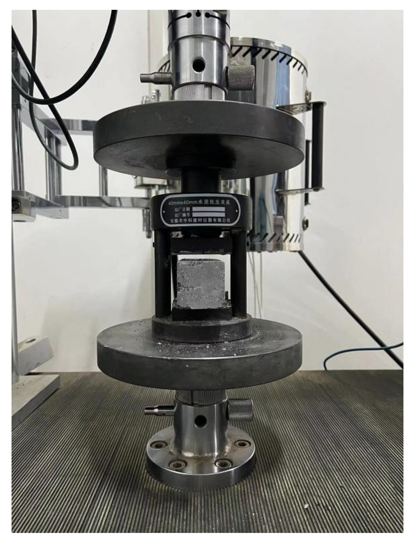
2.5.4. Compressive Strength Test

Following the stipulations of EN-196-1 (2016) [54], a standardized test block measuring 40 mm × 40 mm × 160 mm was employed for assessing compressive strength. The prepared mortar was poured into the designated mold and subjected to curing in a constant temperature environment until reaching the specified ages of 3 days, 7 days and 28 days. A universal testing machine model AI-7000LA manufactured by GOTECH Ltd. (Auckland, New Zealand) was used for compression testing of the specimen blocks with a range of 50 KN and a margin of error of −0.005 to +0.005. The compression rate used in this test was 1 mm/min. Figure 9 shows a picture of the site during the test.

2.5.5. X-ray Diffraction Analysis

Qualitative and quantitative analyses of the phase composition of MA-FA and the prepared powder of the test block were conducted using a Rigaku (Tokyo, Japan) SmartLab SE XRD and MDI Jade 6 software, with the calculation of grain size. To ensure accurate data, it is imperative to adhere to sample preparation guidelines during XRD analysis. Specifically, the bulk sample should undergo soaking in anhydrous ethanol before testing to halt the hydration reaction. Bulk testing necessitates grinding to achieve powders with particle sizes ranging from approximately 10 to 50 microns. Coarser powders may lead to an insufficient number of grains participating in diffraction, causing a lack of random grain orientation in the illuminated volume. Conversely, overly fine powders can diminish the height of the diffraction peak and result in the broadening of the diffraction peak. The test was conducted with a scanning range from 5° to 80° and a step size of 0.0167° (2θ), utilizing Cu-Ka radiation at a scan speed of 0.02°/s. For a comprehensive analysis of phases and hydration products and to enhance the credibility of the XRD results, integration with scanning electron microscopy (SEM) results is imperative.

2.5.6. Scanning Electron Microscopy Analysis

The morphologies of MA-FA and GFC samples were examined using a JSM-7500F SEM manufactured by Nippon Electronics Co., Ltd. (Tokyo, Japan). Additionally, the crystal alterations in MA-FA and the hydration products of GFC were analyzed.

3. Discussion of Results and Analyses

3.1. Effect of Fly Ash Content on Geopolymer Concrete

The FA content influences the component composition of the precursor, impacting the performance of GFC. Excessive FA content disrupts the balance between setting and hardening rates, leading to collapse mold. Collapse mold was observed at an FA content of 90% in this study, rendering the MA0-FA 90 data unsuitable for subsequent analysis.

3.1.1. Effect of Fly Ash Content on Flowability

Figure 10 illustrates the impact of FA content on fluidity, indicating an increase with rising FA content. At 70% FA content, fluidity reaches 21.6 cm, compared to 17.8 cm at 10% FA content, presenting a 3.8 cm difference between the maximum values. This phenomenon is attributed to the spheroidal glassy microstructures of FA, characterized by low surface tension, leading to reduced intergranular cohesion in the precursor [55]. As the FA content increases, these particles grow in number and progressively assume a predominant role in gravity and interparticle attraction. During the flow process, gravity influences frictional forces. With decreasing cohesion and friction, the flow rate rises. However, reduced cohesion between particles leads to a porous structure in the resulting GFC test block, which is unfavorable for the development of compressive strength.

3.1.2. Effect of Fly Ash Content on Expansion Volume and Dry Density

To evaluate its characteristics, this study conducted tests on the volume expansion and dry density of GFC. Figure 11 illustrates the performance outcomes for GFC with varying FA contents. It is evident that with an increase in FA content, there is a rise in volume expansion and a decline in dry density.
Figure 11 and Figure 12 illustrate a positive correlation between the volume expansion of GFC and the FA content, while a negative correlation is observed between dry density and FA content. This implies that a lower FA content in the precursor results in a denser GFC structure. This correlation is intricately linked to the depolymerization–condensation polymerization reaction of the precursor under the influence of the activator. In the course of the precursor’s hydration reaction process, GGBS exhibits high hydration and hardening activity characteristics. In contrast, FA demonstrates low hydration and hardening activity, requiring the destruction of its vitreous sphere structure as a prerequisite in the activation process [56,57]. Generally, GGBS undergoes rapid condensation and hardening. With a high content of precursor GGBS, the GGBS particles are catalyzed by the activator. Ca(OH)2 crystals interact with activated SiO2 and Al2O3, leading to the formation of hydrated calcium silicate gel (C-S-H) and hydrated calcium aluminate crystals endowed with gelling properties [58]. Increasing the GGBS content affects the expansion volume because the gas released from the aluminum powder reaction cannot adequately fill the slurry’s interior due to GFC’s rapid condensation and hardening. As the GGBS reaction time prolongs, the aluminum powder’s outgassing rate diminishes, reaching a point where the degree of condensation and hardening of GGBS no longer supports the outgassing reaction [59].
Figure 12 illustrates the dry density measured after 28 d of GFC curing. The figure indicates a negative correlation between dry density and FA content, associated with the early-stage slurry degassing reaction. Higher FA content leads to a larger expansion volume, signifying that the aluminum powder’s deflation reaction generates more gas trapped in the slurry pores, reducing GFC density. Additionally, an FA depolymerization–polycondensation reaction occurs with an activator, requiring the destruction of the surface layer of the FA spherical glass structure. The Ca/Si ratio of this layer is relatively low. Na+ and Ka+ initially dissolve in OH under the external activator’s influence, leading to the formation of C-S-H gel, C-A-S-H gel and other gels after gradual surface layer destruction. This impedes the depolymerization–condensation polymerization reaction of FA, and prolonged curing may result in incomplete FA reaction, contributing to a decrease in the GFC skeleton structure density. In summary, the volume expansion and dry density of GFC mainly depend on the degassing reaction of aluminum powder and the depolymerization–condensation polymerization reaction of the precursor. When the FA content is 10%, the dry density is the highest, and the volume expansion is the lowest.

3.1.3. Effect of Fly Ash Content on Compressive Strength

The compressive strength of GFC depends on the precursor composition, hydration products and structure. Figure 13 indicates a decrease in the compressive strength with the increasing curing age and FA content. At 10% FA content and a 28 d curing age, GFC achieves its maximum compressive strength of 5.17 MPa, derived from gel formation through precursor depolymerization and condensation polymerization. As FA content increases, the strength improvement diminishes with prolonged curing age. A comparison at 7 d and 28 d curing ages reveals that, at 10% FA content, the compressive strength increases 2.5 times, while the improvement is minimal at 70% FA content. This suggests that GGBS predominantly influences the hydration reaction during the set curing age, and the hydration reaction of FA might remain incomplete within 28 d of the setting age [60].
The compressive strength of GFC is closely tied to its internal structure. As previously noted, the deflation reaction of aluminum powder in the slurry influences the dry density of GFC. With increasing FA content, the dry density decreases, signifying a rise in internal porosity and a less dense structure. This decrease in dry density correlates with a reduction in the compressive strength of GFC blocks as FA content increases, establishing a positive correlation between dry density and compressive strength. In summary, as the FA content increases, the gas trapped in the early-stage slurry increases, resulting in more structural pores and a decrease in dry density, which ultimately leads to a decrease in compressive strength.

3.1.4. Microanalysis of GFC Prepared with Different Fly Ash Contents

Figure 14 illustrates the XRD pattern of GFC after 28 d of curing with varying FA contents. The characteristic peaks in each sample align at similar positions. A new diffraction peak emerged at 29.3°, indicating the presence of calcite, likely formed through carbonization due to the excessive alkalinity of hydration products during the reaction [61]. The wide hump, ranging from 20° to 40°, is attributed to the formation of amorphous gel and partially unreacted GGBS. The intensity of this hump should theoretically increase with higher slag content in the precursor. However, when comparing GFC with varying fly ash content, the intensity of the wide hump remains relatively stable. This is attributed to the complete reaction of GGBS, resulting in the production of calcium silicate-aluminate gel [62]. During the 28 d curing period, the hydration reaction is predominantly influenced by GGBS, resulting in less calcite formation through carbonization, especially when the hydration products are in smaller quantities. With an increase in GGBS content, there is a higher production of calcite through carbonization. In the XRD pattern, when the FA content is less than 50%, the diffraction peak at 29.3° shows reduced intensity and gradually widens FWHM. This is attributed to the alkali activator reacting with more slag, and the presence of the unreacted activator is diminished, leading to a decrease in the carbonization degree of the hydration products. Unreacted crystalline phases of mullite and quartz persist in the precursor, considering inert components that do not partake in the hydration reaction. The observed change in peak intensity primarily stems from the decrease in FA content. As GGBS content increases, the amount of gel produced also rises, correlating with an increase in strength. Moreover, calcite generated through the carbonization of hydration products is detrimental to strength development, causing a reduction in the mechanical properties of GFC to some extent.
Figure 15 shows the SEM diagrams of GFC samples with different fly ash contents amplified 500 times and 2000 times, mainly analyzing the FA reaction and gel formation. Figure 15a,c,e,f show that the unreacted FA gradually decreases, and when the FA content is 10%, the basic reaction is exhausted. Figure 15b,d,f,h show that as the FA content decreases, the gel formation increases. When the fly ash content is 50%, more calcite with a rough surface and flocculated form is displayed. Combined with XRD analysis, the diffraction peak intensity of mullite and quartz in GFC samples is positively correlated with the FA content. The characteristic peak intensity of calcite is the strongest when the FA content is 50%, and the broad hump has little change, all due to the sequence of the depolymerization–condensation reaction of precursors. The gel is mainly formed by the hydration reaction of GGBS. The SEM image magnified 500 times showed that there were still unreacted FAs after 28 d of curing. When the gel production is large, it means that more OH is involved in the reaction, and the alkaline environment is weakened, which inhibits the carbonization of the gel to calcite. Therefore, if the FA content is too high, the mechanical properties of GFC will be weakened.

3.2. Effect of Mechanical Activation Rotation Speed on the Properties of Geopolymer Foam Concrete

To emphasize the enhanced performance of GFC through MA-FA and ensure its optimal characteristics, an FA content of 50% was chosen for mechanical activation. This study aims to analyze how mechanical activation speed influences the hydration reaction of FA.

3.2.1. Effect of Rotational Speed of Mechanical Activation on the Flowability of Concrete

Figure 16 illustrates the correlation between variations in mechanical activation speed and slurry fluidity. Notably, at a rotational speed of 420 rpm, the fluidity reaches its nadir at 19.6 cm, marking a 10.9% reduction compared to the fluidity of slurry prepared with inactivated fly ash. However, at 440 rpm, the fluidity experiences a subsequent increase.
With the increase in mechanical activation speed, the FA spherical glass body gradually breaks, leading to a reduction in surface tension. The resulting uneven surface and increased cohesion between particles contribute to the decreased slurry flow speed. Mechanical activation causes the breakdown of larger particles, leaving only a small portion unbroken, and the uneven surface augments surface friction. As friction rises, surface tension decreases, and cohesion increases, collectively resulting in diminished slurry flow speed. However, at a rotational speed of 440 rpm, the FA spherical glass body tends to circulate along the ball milling tank wall, reducing its impact on FA. This incomplete mechanical activation leaves more unbroken spheres, leading to an increased flow rate and enhanced mobility.

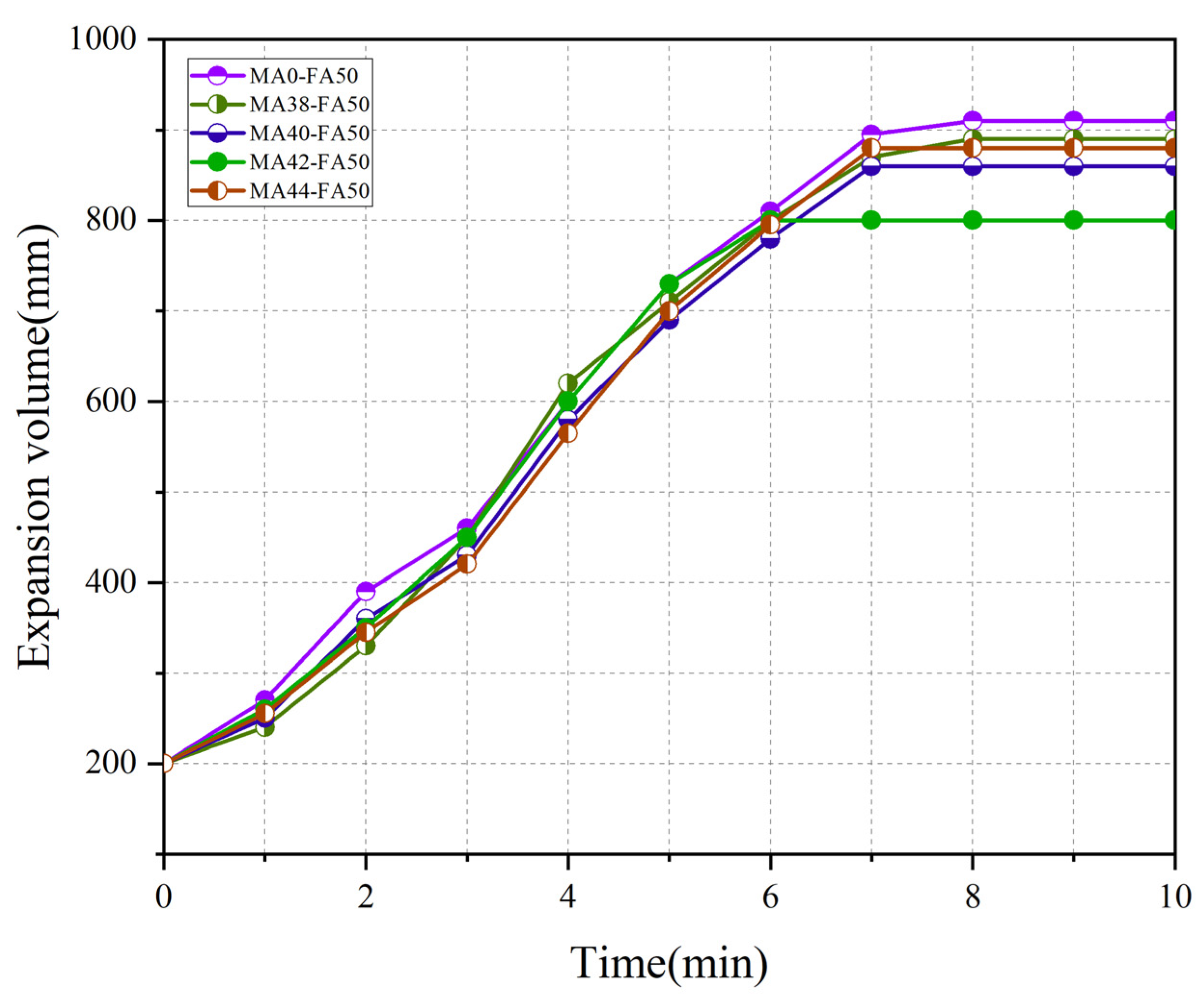
3.2.2. Effect of Mechanical Activation Rotation Speed on Swelling Volume and Dry Density

Figure 17 displays the volume expansion of GFC during the foaming process with varying mechanical activation speeds. The volume expansion exhibited varying degrees of decrease with changes in mechanical activation speed. At a rotational speed of 420 rpm, the volume expansion was minimized, and the expansion time was the shortest, reduced by 12.2% compared to GFC prepared without ball-milling FA. As indicated in Figure 3, at a rotation speed of 420 rpm, mechanical activation is most complete, resulting in the greatest damage to FA spheres and bringing the internal silicon-rich and aluminum-rich contents into contact with the exterior. When the OH in the activator is in contact with it, the activation reaction of FA can be accelerated, resulting in AlO 3 and SiO 4 4 , and C-A-S-H gel is formed by depolymerization and condensation polymerization. Simultaneously, the foaming rate of aluminum powder is constrained. At a mechanical activation speed of 440 rpm, the impact on FA diminishes as FA particles float along the inner wall of the ball mill tank during rotation. Inadequate activation of FA hinders its hydration reaction, leading to a comparatively higher foaming rate of aluminum powder.
Figure 18 illustrates the dry density of GFC prepared from mechanically activated fly ash at various rotational speeds. At a rotational speed of 420 rpm, the dry density peaks at 412.37 kg/m3, marking an 11.1% increase compared to GFC crafted from non-mechanically activated FA. The reduction in the surface area of MA-FA spheres fosters a more effective hydration reaction, creating gel nucleation points and enhancing the pore wall density of GFC. This results in a denser internal structure and an improved dry density. Moreover, there exists a negative correlation between dry density and volume expansion value. The pre-reacted OH with MA-FA effectively inhibits the gas reaction of aluminum powder, reducing trapped gas and, consequently, internal porosity.

3.2.3. Effect of Mechanically Activated Rotation Speed on Compressive Strength

Figure 19 displays the compressive strengths of GFC specimens crafted at varying rotational speeds and ages. Overall, compressive strength increases with curing age. The compressive strength of GFC shows a gradual increase with the elevation of mechanical speed. However, at a speed of 440 rpm, there is a subsequent decrease in compressive strength. This change is mainly attributed to the degree of activation. The maximum compressive strength, reaching 1.69 MPa at 420 rpm, is 17.4% higher than that of GFC prepared with raw FA. With an extended curing age, the impact of MA-FA on compressive strength becomes more apparent. At the curing age of 3 d, the compressive strengths of GFC are similar regardless of mechanical activation speed. However, starting from the curing age of 7 d, the compressive strength of GFC prepared with MA-FA surpasses that of GFC prepared with raw fly ash. Notably, at a mechanical activation speed of 420 rpm, the strength increase is most pronounced. This enhancement could be attributed to the destruction of the spherical glass body of fly ash during the preparation of MA-FA, facilitating easier contact between internal Al and Si compounds with the activator. This, in turn, accelerates the hydration reaction, leading to the production of more gels. Additionally, the conversion of some SiO2 and mullite crystals in MA-FA into amorphous states results in the generation of more tetrahedral structures [SiO4] and [AlO4], contributing to the hydration products [25], and the strength of GFC can be enhanced to a considerable extent. Figure 20 illustrates the variations in the ratios of compressive strengths to dry density (specific strength) of GFC with the rotational speed of mechanical activation. It is evident that the specific strength reaches a peak of 0.041 MPa when the rotational speed attains 420 rpm. This value surpasses that reported by Xiong et al. for foam concrete prepared under similar alkalinity conditions, indicating the successful achievement of a lightweight and high-strength effect in the prepared GFC at this rotational speed [63,64]. Furthermore, the mechanical activation of fly ash proves effective in diminishing the surface area of fly ash particles, resulting in a more compact geopolymer structure and offering nucleation points for hydration products.
In summary, the enhancement in the strength of GFC prepared using MA-FA primarily arises from the alteration in the microstructure of fly ash and the transformation of certain crystal structures into an amorphous state.

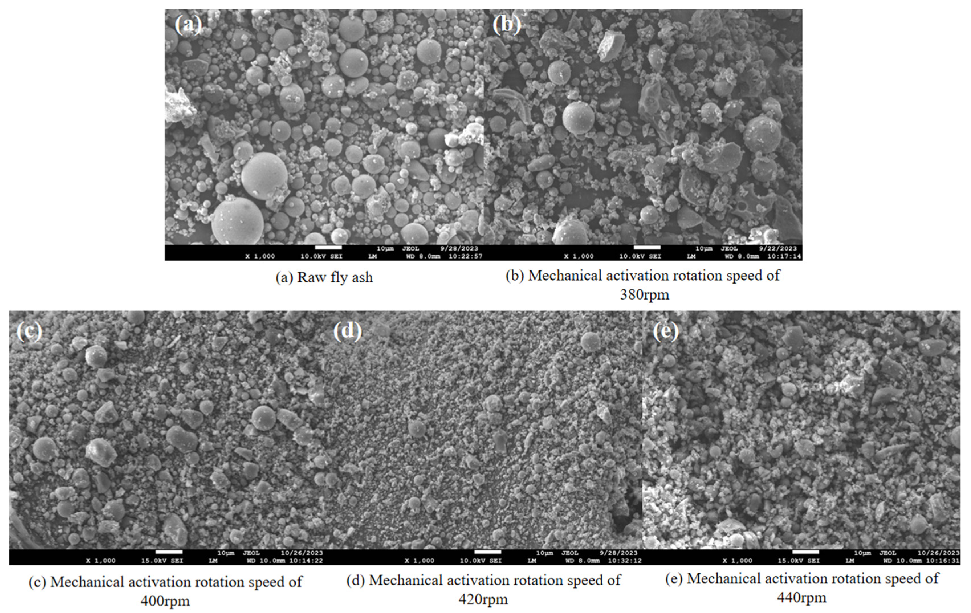
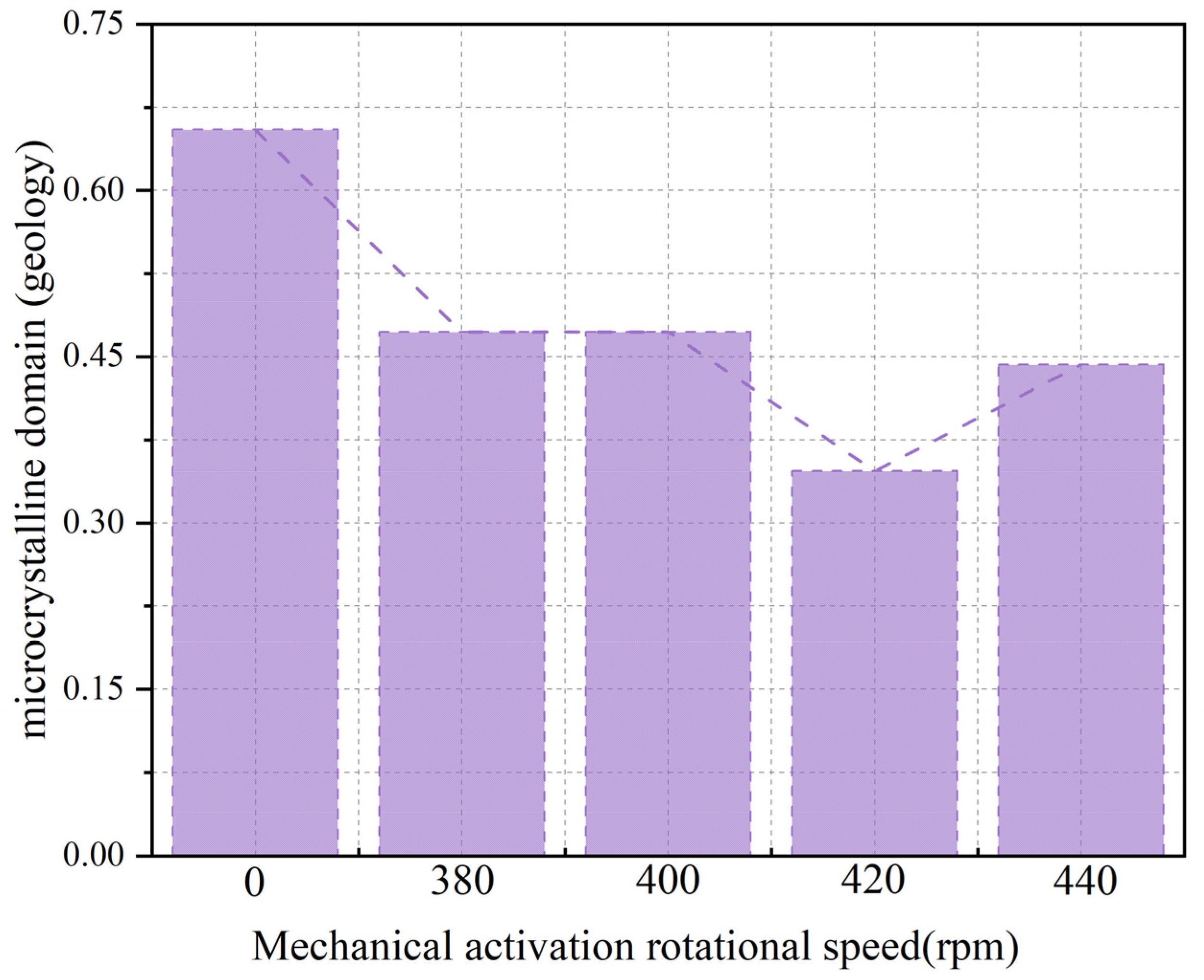
3.2.4. Microanalysis of GFC Prepared with Different Mechanical Activation Rotation Speeds

Figure 21 presents the XRD patterns of MA-FA production and GFC curing at 28 d with different activation speeds. The calcite characteristic peak of MA 0-FA 50 is notably higher than others, indicating that FA in the matrix is less involved in the hydration reaction, and the alkali content is relatively high, creating conditions for gel carbonization. This presence of calcite reduces strength. With the increase in mechanical activation speed, the strengths of the quartz and mullite phases initially increase and then decrease, reaching their lowest in MA 42-FA 50. This is mainly due to the transformation of the original crystal structure into an amorphous state through mechanical activation, participating in the internal reaction to produce an amorphous gel. The speed of MA 44-FA 50 is too high, resulting in insufficient ball milling and leading to a higher presence of polycrystalline phases and lower amorphous gel production. The hump angle of the gel interval in MA 42-FA 50 is the smallest compared to others, indicating that MA-FA promotes the hydration reaction of slag, converting more GGBS into amorphous gel under the action of the alkali activator.
Figure 22 presents the SEM images of GFC at the curing age of 28 d prepared using MA-FA produced at various mechanical activation speeds. The GFCs in Figure 22a,c,e,g,i are magnified 500 times. It is evident that, with an increase in the mechanical activation speed, the pore walls of the prepared GFC become more uniform. An inflection point appears when the rotational speed exceeds 420 rpm. This observation is attributed to the effective hydration of activated FA within the 28-day curing period. The pore wall morphology at the mechanical activation speed of 420 rpm, as seen in Figure 18, exhibits fewer unreacted FA particles, a flat surface and a denser structure. Figure 22h displays SEM images at 2000 times this speed. At this point, there is a notable increase in the gel content, accompanied by a partial reduction in the presence of calcite. This is attributed to the complete activation of FA at this rotational speed, reaching an optimal activation state and supplying nucleation points for gel formation. The early engagement of FA in the reaction process led to a decrease in the alkaline composition of the activator, disrupting the carbonization environment of the gel. Figure 22b,d,f,h,j reveal that GFC prepared with MA-FA yields significantly more gel than the counterpart prepared with original FA. This trend becomes more pronounced with the escalating mechanical activation speed, reaching an optimum at 420 rpm. These findings underscore the positive impact of MA-FA on gel formation. Additionally, SEM images of GFC prepared with MA-FA illustrate a gradual reduction in calcite content, reaching a minimum at 420 rpm, aligning with the conclusions drawn from the XRD analysis.

4. Conclusions

In this investigation, we assessed the blending ratio of FA-GGBS-based GFC precursors and examined the impact of MA-FA on the evolution of compressive strength and rheological properties through experimental methods. Utilizing XRD and SEM, we explored the influence of hydration reactions and mechanical activations within GFC on FA. The specific findings are outlined below:
  • With the increase in the mechanical activation speed, the size of fly ash microcrystalline domains showed a tendency of decreasing first and then increasing. The minimum value was 0.35.
  • The compressive strength of GFC demonstrated an increase with the reduction in FA content, reaching a maximum strength of 5.17 MPa, which is 7.6 times the minimum strength value. This trend can be attributed to the decrease in the content of CaO and SiO2 with the increase in FA content. The hydration reaction is primarily governed by CaO and SiO2, facilitating gel formation, suppressing the gas-forming reaction of aluminum powder and enhancing the dry density of GFC. Consequently, the structural density is improved.
  • Compared to GFC prepared using raw FA and MA-FA, the specific strength of GFC prepared by MA-FA demonstrated a certain improvement, indicating the achievement of lightweight and high-strength characteristics. Notably, the specific strength of GFC prepared by MA-FA at 420 rpm was the highest, showing a 10.5% increase compared to GFC prepared using raw FA.
Future studies could delve into the effects of mechanical activation time, alkalinity and modulus on the rheological and mechanical properties of GFC. In future studies, we will introduce statistical theories such as the introduction of p-values and confidence intervals for in-depth studies.

Author Contributions

X.L.: Funding Acquisition, Project Administration, Writing—Original Draft. T.J.: Formal Analysis, Methodology, Visualization, Writing—Original Draft, Writing—Review and Editing. C.L.: Investigation, Validation, Writing—Review and Editing. M.W.: Conceptualization, Investigation, Formal Analysis. W.X.: Methodology, Data Curation, Writing—Review. X.W.: Funding Acquisition, Project Administration. All authors have read and agreed to the published version of the manuscript.

Funding

The authors would like to acknowledge the financial support received from the University Natural Science Research Project of Anhui Province (CN) (Grant No. 2022AH050261), Doctoral Startup Foundation from Anhui Jianzhu University (Grant No. 2022QDZ23), Open Foundation of National-Local Joint Engineering Laboratory of Building Health Monitoring and Disaster Prevention Technology (Grant No. GG22KF003), Key Science and Technology Program of Anhui Province of China (Grant No. 2021001), Natural Science Foundation of Anhui Province (Grant No. 2108085ME142) and Anhui Province Housing and Urban Rural Construction Science and Technology Plan Project (Grant No. 2021-RK02).

Data Availability Statement

The original contributions presented in the study are included in the article, further inquiries can be directed to the corresponding author.

Conflicts of Interest

The authors declare that they have no known competing financial interests or personal relationships that might influence the work reported here.

References

  1. Tamanna, K.; Raman, S.N.; Jamil, M.; Hamid, R. Utilization of wood waste ash in construction technology: Review. Construct. Build. Mater. 2020, 237, 117654. [Google Scholar] [CrossRef]
  2. Amran, Y.H.M.; Alyousef, R.; Alabduljabbar, H.; El-Zeadani, M. Clean production and properties of geopolymer concrete: A review. J. Clean. Prod. 2020, 251, 119679. [Google Scholar] [CrossRef]
  3. Norgate, T.; Haque, N. Energy and greenhouse gas impacts of mining and mineral processing operations. J. Clean. Prod. 2010, 18, 266–274. [Google Scholar] [CrossRef]
  4. Singh, G.V.P.B.; Subramaniam, K.V.L. Production and characterization of low-energy Portland composite cement from post-industrial waste. J. Clean. Prod. 2019, 239, 118024. [Google Scholar] [CrossRef]
  5. Imbabi, M.S.; Carrigan, C.; McKenna, S. Trends and developments in green cement and concrete technology. Int. J. Sustain. Built Environ. 2012, 1, 194–216. [Google Scholar] [CrossRef]
  6. Meyer, C. The greening of the concrete industry. Cem. Concr. Compos. 2009, 31, 601–605. [Google Scholar] [CrossRef]
  7. Shehab, H.K.; Eisa, A.S.; Wahba, A.M. Mechanical properties of fly ash based geopolymer concrete with full and partial cement replacement. Constr. Build. Mater. 2016, 126, 560–565. [Google Scholar] [CrossRef]
  8. Şahin, O.; İlcan, H.; Ateşli, A.T.; Kul, A.; Yıldırım, G.; Şahmaran, M. Construction and demolition waste-based geopolymers suited for use in 3-dimensional additive manufacturing. Cem. Concr. Compos. 2021, 121, 104088. [Google Scholar] [CrossRef]
  9. Davidovits, J. (Ed.) Geopolymer Chemistry and Applications, 5th ed.; Geopolymer Institute: Saint-Quentin, France, 2020. [Google Scholar]
  10. Shehata, N.; Mohamed, O.A.; Sayed, E.T.; Abdelkareem, M.A.; Olabi, A.G. Geopolymer concrete as green building materials: Recent applications, sustainable development and circular economy potentials. Sci. Total Environ. 2022, 836, 155577. [Google Scholar] [CrossRef] [PubMed]
  11. Zhang, Z.; Provis, J.L.; Reid, A.; Wang, H. Mechanical, thermal insulation, thermal resistance and acoustic absorption properties of geopolymer foam concrete. Cem. Concr. Compos. 2015, 62, 97–105. [Google Scholar] [CrossRef]
  12. Shi, J.; Liu, Y.; Wang, E.; Wang, L.; Li, C.; Xu, H.; Zheng, X.; Yuan, Q. Physico-mechanical, thermal properties and durability of foamed geopolymer concrete containing cenospheres. Constr. Build. Mater. 2022, 325, 126841. [Google Scholar] [CrossRef]
  13. Klima, K.M.; Schollbach, K.; Brouwers, H.J.H.; Yu, Q. Thermal and fire resistance of Class F fly ash based geopolymers—A review. Constr. Build. Mater. 2022, 323, 126529. [Google Scholar] [CrossRef]
  14. Kaplan, G.; Bayraktar, O.Y.; Bayrak, B.; Celebi, O.; Bodur, B.; Oz, A.; Aydin, A.C. Physico-mechanical, thermal insulation and resistance characteristics of diatomite and attapulgite based geopolymer foam concrete: Effect of different curing regimes. Constr. Build. Mater. 2023, 373, 130850. [Google Scholar] [CrossRef]
  15. Yang, S.; Wang, X.; Hu, Z.; Li, J.; Yao, X.; Zhang, C.; Wu, C.; Zhang, J.; Wang, W. Recent advances in sustainable lightweight foamed concrete incorporating recycled waste and byproducts: A review. Constr. Build. Mater. 2023, 403, 133083. [Google Scholar] [CrossRef]
  16. Kočí, V.; Černý, R. Directly foamed geopolymers: A review of recent studies. Cem. Concr. Compos. 2022, 130, 104530. [Google Scholar] [CrossRef]
  17. Mao, Q.; Li, Y.; Liu, K.; Peng, H.; Shi, X. Mechanism, characterization and factors of reaction between basalt and alkali: Exploratory investigation for potential application in geopolymer concrete. Cem. Concr. Compos. 2022, 130, 104526. [Google Scholar] [CrossRef]
  18. Singh, R.P.; Vanapalli, K.R.; Cheela, V.R.S.; Peddireddy, S.R.; Sharma, H.B.; Mohanty, B. Fly ash, GGBS, and silica fume based geopolymer concrete with recycled aggregates: Properties and environmental impacts. Constr. Build. Mater. 2023, 378, 131168. [Google Scholar] [CrossRef]
  19. Hou, L.; Li, J.; Lu, Z.; Niu, Y. Influence of foaming agent on cement and foam concrete. Constr. Build. Mater. 2021, 280, 122399. [Google Scholar] [CrossRef]
  20. Hao, Y.; Yang, G.; Liang, K. Development of fly ash and slag based high-strength alkali-activated foam concrete. Cem. Concr. Compos. 2022, 128, 104447. [Google Scholar] [CrossRef]
  21. Gao, H.; Wang, W.; Liao, H.; Cheng, F. Characterization of light foamed concrete containing fly ash and desulfurization gypsum for wall insulation prepared with vacuum foaming process. Constr. Build. Mater. 2021, 281, 122411. [Google Scholar] [CrossRef]
  22. Sun, D.; Huang, N.; Liu, K.; Tang, J.; Rong, N.; Wang, A.; Guan, Y.; Liang, P.; Deng, Y. Effect of recycled fine powder on autoclaved aerated concrete: Gas-foaming, physic-mechanical property and hydration products. J. Build. Eng. 2023, 67, 106013. [Google Scholar] [CrossRef]
  23. Grabias-Blicharz, E.; Franus, W. A critical review on mechanochemical processing of fly ash and fly ash-derived materials. Sci. Total Environ. 2023, 860, 160529. [Google Scholar] [CrossRef]
  24. Gopalakrishna, B.; Pasla, D. Development of metakaolin based high strength recycled aggregate geopolymer concrete. Constr. Build. Mater. 2023, 391, 131810. [Google Scholar] [CrossRef]
  25. Singh, B.; Ishwarya, G.; Gupta, M.; Bhattacharyya, S.K. Geopolymer concrete: A review of some recent developments. Constr. Build. Mater. 2015, 85, 78–90. [Google Scholar] [CrossRef]
  26. Zhang, D.; Yang, Z.; Kang, D.; Fang, C.; Jiao, Y.; Wang, K.; Mi, S. Study on the mechanism of Ca2+ and Na+ interaction during the hydration of multi-source solid waste geopolymers. J. Build. Eng. 2023, 69, 106177. [Google Scholar] [CrossRef]
  27. Long, Q.; Liu, Y.; Zhao, Q.; Zhou, M.; Li, B. Effects of GGBFS:FA ratio and humid-heat-treating on the mechanical performance and microstructure of the steel slag-based ternary geopolymer. Constr. Build. Mater. 2023, 392, 131750. [Google Scholar] [CrossRef]
  28. Fan, M.X.; Chen, F.X.; Zhang, X.Y.; Wang, R.K.; Yu, R. Effect of Ca/Si ratio on the characteristics of alkali-activated ultra- high performance concrete (A-UHPC): From hydration kinetics to microscopic structure development. Constr. Build. Mater. 2023, 394, 132158. [Google Scholar] [CrossRef]
  29. Zhang, M.; Zhang, C.; Zhang, J.; Wang, L.; Wang, F. Effect of composition and curing on alkali activated fly ash-slag binders: Machine learning prediction with a random forest-genetic algorithm hybrid model. Constr. Build. Mater. 2023, 366, 129940. [Google Scholar] [CrossRef]
  30. Tian, Z.; Zhang, Z.; Tang, X.; Zhang, Y.; Gui, Z.; Tan, J.; Chang, Q. Understanding the effect of moisture on interfacial behaviors of geopolymer-aggregate interaction at molecular level. Constr. Build. Mater. 2023, 385, 131404. [Google Scholar] [CrossRef]
  31. Li, Y.; Sun, Z.; Li, Z.; Chen, B.; Li, Z. Dimeric and oligomeric interactions between calcium silicate aqua monomers before calcium silicate hydrate nucleation. Cem. Concr. Res. 2023, 173, 107297. [Google Scholar] [CrossRef]
  32. Rodriguez, V.A.; Ribas, L.; Kwade, A.; Tavares, L.M. Mechanistic modeling and simulation of a wet planetary ball mill. Powder Technol. 2023, 429, 118901. [Google Scholar] [CrossRef]
  33. Ye, X.; Bai, Y.; Chen, C.; Cai, X.; Fang, J. Analysis of dynamic similarity and energy-saving mechanism of the grinding process in a horizontal planetary ball mill. Adv. Powder Technol. 2015, 26, 409–414. [Google Scholar] [CrossRef]
  34. Guzzo, P.L.; Marinho de Barros, F.B.; Soares, B.R.; Santos, J.B. Evaluation of particle size reduction and agglomeration in dry grinding of natural quartz in a planetary ball mill. Powder Technol. 2020, 368, 149–159. [Google Scholar] [CrossRef]
  35. Rajak, D.K.; Raj, A.; Guria, C.; Pathak, A.K. Grinding of Class-F fly ash using planetary ball mill: A simulation study to determine the breakage kinetics by direct- and back-calculation method. S. Afr. J. Chem. Eng. 2017, 24, 135–147. [Google Scholar] [CrossRef]
  36. Sun, Y.; Wang, Z.H.; Park, D.J.; Kim, W.S.; Kim, H.S.; Yan, S.R.; Lee, H.S. Analysis of the isothermal hydration heat of cement paste containing mechanically activated fly ash. Thermochim. Acta 2022, 715, 179273. [Google Scholar] [CrossRef]
  37. Zhou, H.; Chen, Y.; Li, H.; Xu, Z.; Dong, H.; Wang, W. Effect of particles micro characteristics destroyed by ball milling on fly ash electrostatic separation. Adv. Powder Technol. 2022, 33, 103449. [Google Scholar] [CrossRef]
  38. Sundum, T.; Szécsényi, K.M.; Kaewtatip, K. Preparation and characterization of thermoplastic starch composites with fly ash modified by planetary ball milling. Carbohydr. Polym. 2018, 191, 198–204. [Google Scholar] [CrossRef] [PubMed]
  39. Nath, S.K.; Kumar, S. Reaction kinetics of fly ash geopolymerization: Role of particle size controlled by using ball mill. Adv. Powder Technol. 2019, 30, 1079–1088. [Google Scholar] [CrossRef]
  40. Zhang, Q.; Huang, D.; Zhang, X.; Lin, L.; Wang, Z.; Tang, W.; Qiang, X. Improving the properties of metakaolin/fly ash composite geopolymers with ultrafine fly ash ground by steam-jet mill. Constr. Build. Mater. 2023, 387, 131673. [Google Scholar] [CrossRef]
  41. Li, H.; Chen, Y.; Cao, Y.; Liu, G.; Li, B. Comparative study on the characteristics of ball-milled coal fly ash. J. Therm. Anal. Calorim. 2016, 124, 839–846. [Google Scholar] [CrossRef]
  42. Hajimohammadi, A.; van Deventer, J.S.J. Dissolution behaviour of source materials for synthesis of geopolymer binders: A kinetic approach. Int. J. Miner. Process. 2016, 153, 80–86. [Google Scholar] [CrossRef]
  43. Ambrus, M.; Mucsi, G. Advanced processing of high Ca fly ash for enhanced reactivity and improved high value-added application possibilities. Case Stud. Constr. Mater. 2023, 18, e02214. [Google Scholar] [CrossRef]
  44. Azarhomayun, F.; Haji, M.; Kioumarsi, M.; Shekarchi, M. Effect of calcium stearate and aluminum powder on free and restrained drying shrinkage, crack characteristic and mechanical properties of concrete. Cem. Concr. Compos. 2022, 125, 104276. [Google Scholar] [CrossRef]
  45. Chindaprasirt, P.; Jitsangiam, P.; Rattanasak, U. Hydrophobicity and efflorescence of lightweight fly ash geopolymer incorporated with calcium stearate. J. Clean. Prod. 2022, 364, 132449. [Google Scholar] [CrossRef]
  46. Chen, R.; Liu, J.; Mu, S. Chloride ion penetration resistance and microstructural modification of concrete with the addition of calcium stearate. Constr. Build. Mater. 2022, 321, 126188. [Google Scholar] [CrossRef]
  47. Wang, C.C.; Dong, K.J.; Zou, R.P.; Yu, A.B. How stars are packed in the universe: A comparison with sphere packing. Powder Technol. 2021, 381, 224–228. [Google Scholar] [CrossRef]
  48. Yang, J.; Tang, Y.; He, X.; Su, Y.; Zeng, J.; Ma, M.; Zeng, L.; Zhang, S.; Tan, H.; Strnadel, B. An efficient approach for sustainable fly ash geopolymer by coupled activation of wet-milling mechanical force and calcium hydroxide. J. Clean. Prod. 2022, 372, 133771. [Google Scholar] [CrossRef]
  49. Basak, M.; Rahman, M.L.; Ahmed, M.F.; Biswas, B.; Sharmin, N. The use of X-ray diffraction peak profile analysis to determine the structural parameters of cobalt ferrite nanoparticles using Debye-Scherrer, Williamson-Hall, Halder-Wagner and Size-strain plot: Different precipitating agent approach. J. Alloys Compd. 2022, 895, 162694. [Google Scholar] [CrossRef]
  50. Ding, C.; Ma, W.; Zhong, J. The influence of microcrystalline structure and crystalline size on visible light transmission of polyvinyl alcohol optical films. Opt. Mater. 2024, 147, 114627. [Google Scholar] [CrossRef]
  51. Lei, L.; Xiang, J.-H.; Zeng, F.-G.; Deng, X.-P. High resolution TEM image analysis of anthracite coal microcrystalline structure. J. Fuel Chem. Technol. 2021, 49, 742–751. [Google Scholar] [CrossRef]
  52. BS EN 1015-3; Methods of Test for Mortar for Masonry—Part 3: Determination of Consistence of Fresh Mortar (by Flow Table). The British Standards Institution: London, UK, 1999.
  53. ASTM C157/C157M-17; Standard Test Method for Length Change of Hardened Hydraulic-Cement Mortar and Concrete. ASTM International: West Conshohocken, PA, USA, 2017.
  54. BS EN 196-1; Methods of Testing Cement—Part 1: Determination of Strength. The British Standards Institution: London, UK, 2016.
  55. Dong, D.; Huang, Y.; Pei, Y.; Zhang, X.; Cui, N.; Zhao, P.; Hou, P.; Lu, L. Effect of spherical silica fume and fly ash on the rheological property, fluidity, setting time, compressive strength, water resistance and drying shrinkage of magnesium ammonium phosphate cement. J. Build. Eng. 2023, 63, 105484. [Google Scholar] [CrossRef]
  56. Lin, W.-T. Reactive ultra-fine fly ash as an additive for cement-based materials. Mater. Today Commun. 2020, 25, 101466. [Google Scholar] [CrossRef]
  57. Soundarya, N. Effect of fly ash and GGBS on lime stabilized mud block. Mater. Today Proc. 2021, 47, 4636–4640. [Google Scholar] [CrossRef]
  58. Prusty, J.K.; Pradhan, B. Evaluation of durability and microstructure evolution of chloride added fly ash and fly ash-GGBS based geopolymer concrete. Constr. Build. Mater. 2023, 401, 132925. [Google Scholar] [CrossRef]
  59. Xia, D.; Chen, R.; Cheng, J.; Tang, Y.; Xiao, C.; Li, Z. Desert sand-high calcium fly ash-based alkali-activated mortar: Flowability, mechanical properties, and microscopic analysis. Constr. Build. Mater. 2023, 398, 131729. [Google Scholar] [CrossRef]
  60. Mohamed, O.A.; Najm, O.; Ahmed, E. Alkali-activated slag & fly ash as sustainable alternatives to OPC: Sorptivity and strength development characteristics of mortar. Clean. Mater. 2023, 8, 100188. [Google Scholar]
  61. Liu, T.; Gong, C.; Duan, L.; Qu, B. Effects of sodium citrate on compressive strength and microstructure of NaOH-activated fly ash/slag cement exposed to high temperature. Constr. Build. Mater. 2023, 363, 129852. [Google Scholar] [CrossRef]
  62. Zhang, J.; Shi, C.; Zhang, Z. Effect of Na2O concentration and water/binder ratio on carbonation of alkali-activated slag/fly ash cements. Constr. Build. Mater. 2021, 269, 121258. [Google Scholar] [CrossRef]
  63. Liu, Y.-L.; Liu, C.; Qian, L.-P.; Wang, A.-G.; Sun, D.-S.; Guo, D. Foaming processes and properties of geopolymer foam concrete: Effect of the activator. Constr. Build. Mater. 2023, 391, 131830. [Google Scholar] [CrossRef]
  64. Xiong, Y.; Hu, Z.; Liu, C.; Zhang, C.; Zhang, Y. Unveiling the role of Portland cement and fly ash in pore formation and its influence on properties of hybrid alkali-activated foamed concrete. Constr. Build. Mater. 2024, 411, 134336. [Google Scholar]
Figure 1. Horizontal planetary ball mill working principle diagram.
Buildings 14 00841 g001
Figure 2. Composition contents of fly ash.
Buildings 14 00841 g002
Figure 3. Composition contents of GGBS.
Buildings 14 00841 g003
Figure 4. Scanning electron micrographs of fly ash activated at different rotational speeds.
Buildings 14 00841 g004
Figure 5. Scanning electron micrographs of GGBS.
Buildings 14 00841 g005
Figure 6. XRD analysis results of fly ash mechanically activated by different rotational speeds and slag.
Buildings 14 00841 g006
Figure 7. Variation of microcrystalline domain size with rotational speed of mechanical activation.
Buildings 14 00841 g007
Figure 8. Geopolymer foam concrete preparation process.
Buildings 14 00841 g008
Figure 9. Universal testing machine test situation.
Buildings 14 00841 g009
Figure 10. Relationship between fly ash content and flowability.
Buildings 14 00841 g010
Figure 11. Volume expansions for different fly ash contents.
Buildings 14 00841 g011
Figure 12. Dry densities for different fly ash contents.
Buildings 14 00841 g012
Figure 13. Relationships between fly ash contents and GFC compressive strengths for different fly ash contents.
Buildings 14 00841 g013
Figure 14. XRD patterns of GFC prepared with different fly ash contents.
Buildings 14 00841 g014
Figure 15. Scanning electron micrographs of GFC prepared with different fly ash contents.
Buildings 14 00841 g015
Figure 16. Relationship between concrete flowability and mechanical activation speed.
Buildings 14 00841 g016
Figure 17. Volume expansions for different mechanical activation rotation speeds.
Buildings 14 00841 g017
Figure 18. Dry densities for different mechanical activation rotation speeds.
Buildings 14 00841 g018
Figure 19. Relationships between mechanically activated rotation speeds and GFC compressive strengths at different ages.
Buildings 14 00841 g019
Figure 20. Relationship between speed of rotation and specific strength of mechanical activation.
Buildings 14 00841 g020
Figure 21. XRD spectra of GFC prepared from fly ash with different mechanical activation speeds.
Buildings 14 00841 g021
Figure 22. SEM spectra of GFC prepared from fly ash with different mechanical activation speeds.
Buildings 14 00841 g022
Table 1. The chemical composition of fly ash and slag.
MaterialsChemical Composition (%)
SiO2Al2O3CaOFe2O3K2OMgOTiO2SO3
FA46.838.883.634.141.430.521.721.72
GGBS27.615.0743.050.410.448.970.932.42
Table 2. Geopolymer foam concrete mixing ratio.
Sample NumberFly
Ash (g)
GGBS (g)MA
Speed (rpm)
MA
Time (h)
Water (g)Water Glass (g)NaOH (g)Al
Powder (g)
Calcium Stearate (g)
MA0-FA1010900325414.50.30.1
MA0-FA3030700325414.50.30.1
MA0-FA5050500325414.50.30.1
MA0-FA7070300325414.50.30.1
MA0-FA9090100325414.50.30.1
MA38-FA505050380325414.50.30.1
MA40-FA505050400325414.50.30.1
MA42-FA505050420325414.50.30.1
MA44-FA505050440325414.50.30.1
Disclaimer/Publisher’s Note: The statements, opinions and data contained in all publications are solely those of the individual author(s) and contributor(s) and not of MDPI and/or the editor(s). MDPI and/or the editor(s) disclaim responsibility for any injury to people or property resulting from any ideas, methods, instructions or products referred to in the content.

