

Out-of-Plane Strengthening of Existing Timber Floors with Cross Laminated Timber Panels Made of Short Supply Chain Beech


Abstract
:1. Introduction
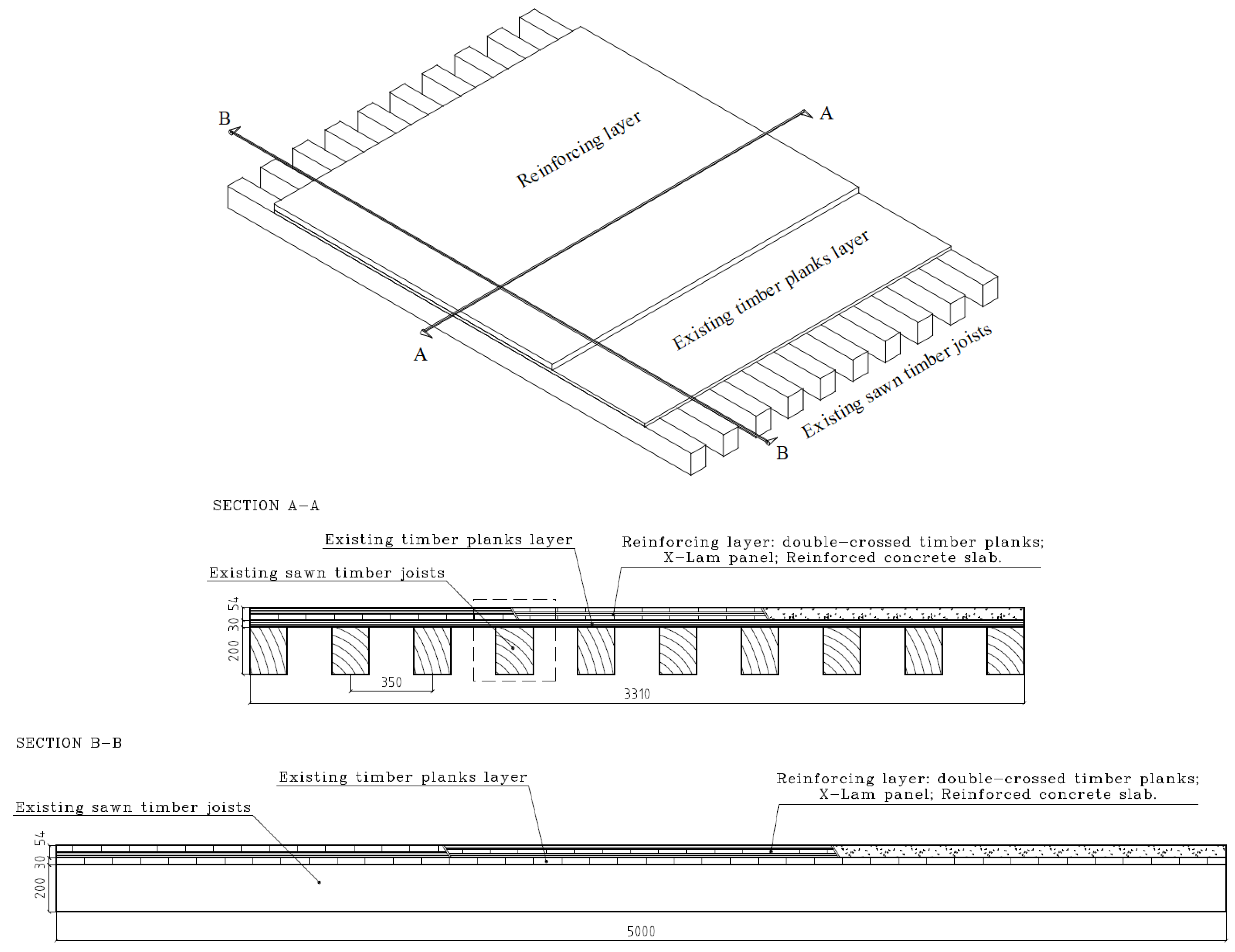
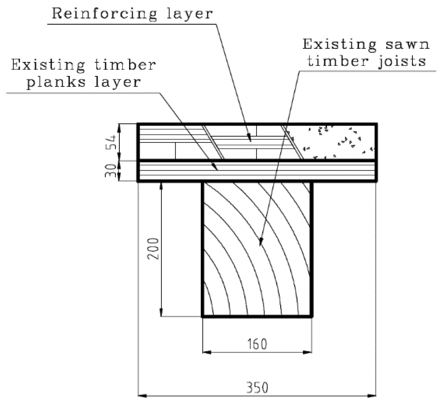
2. Reinforcing Interventions
- a double-crossed timber planking, made of hardwood, with a mean modulus of elasticity parallel to the grain Emean,II = 14,237 MPa and a mean density ρmean = 756 kg/m3;
- a RC slab with secant modulus of elasticity Ec = 31,447 MPa and ρmean = 2500 kg/m3.
3. Comparison of Selected Intervention Techniques
3.1. Calculation Approach
3.2. Slip Moduli and Performance
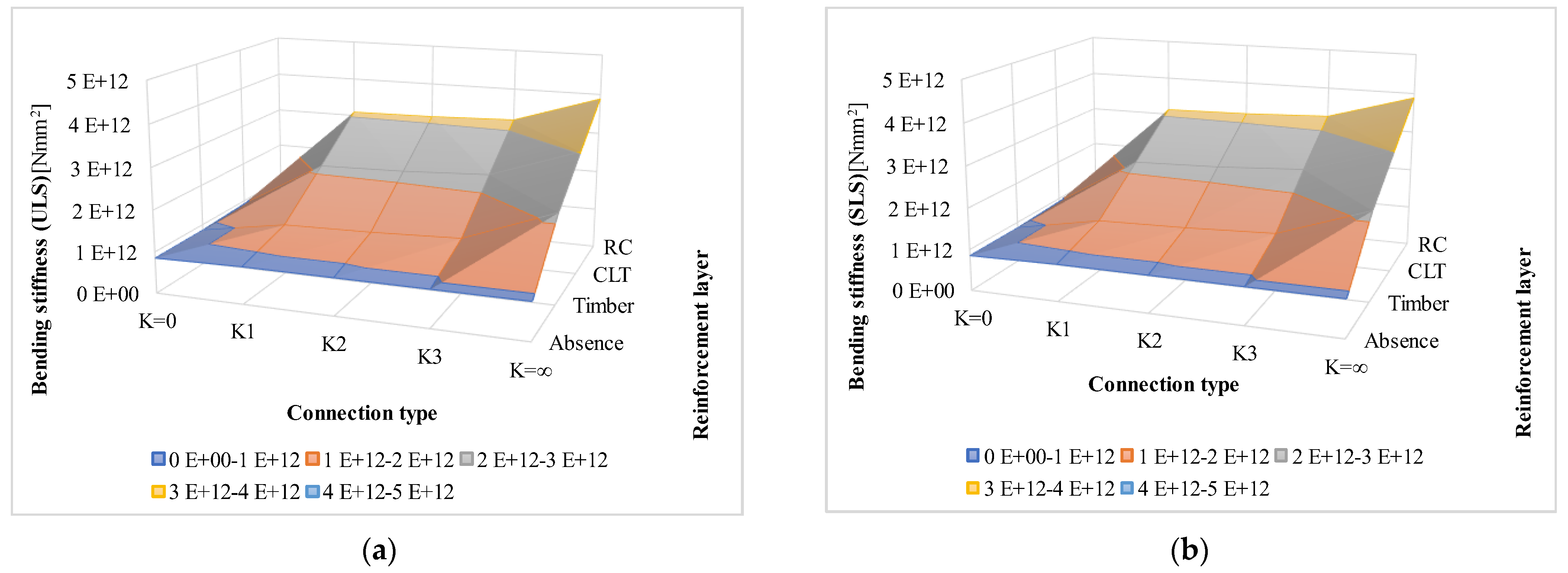
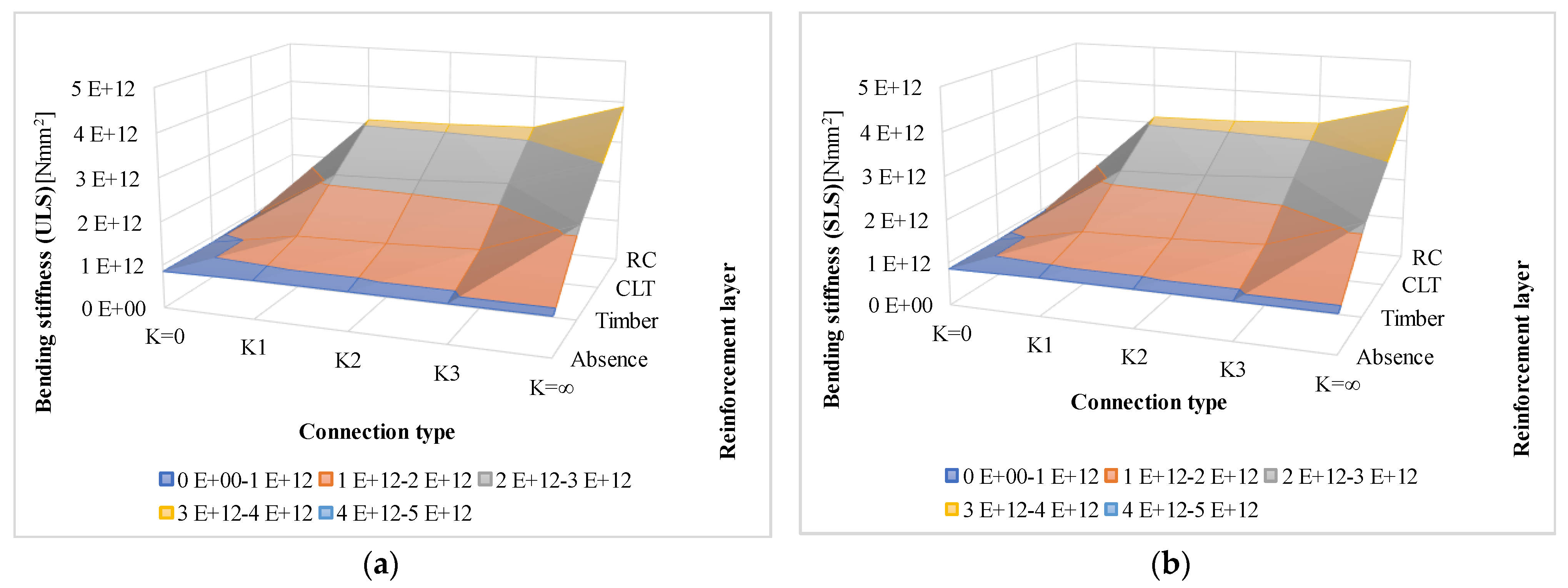
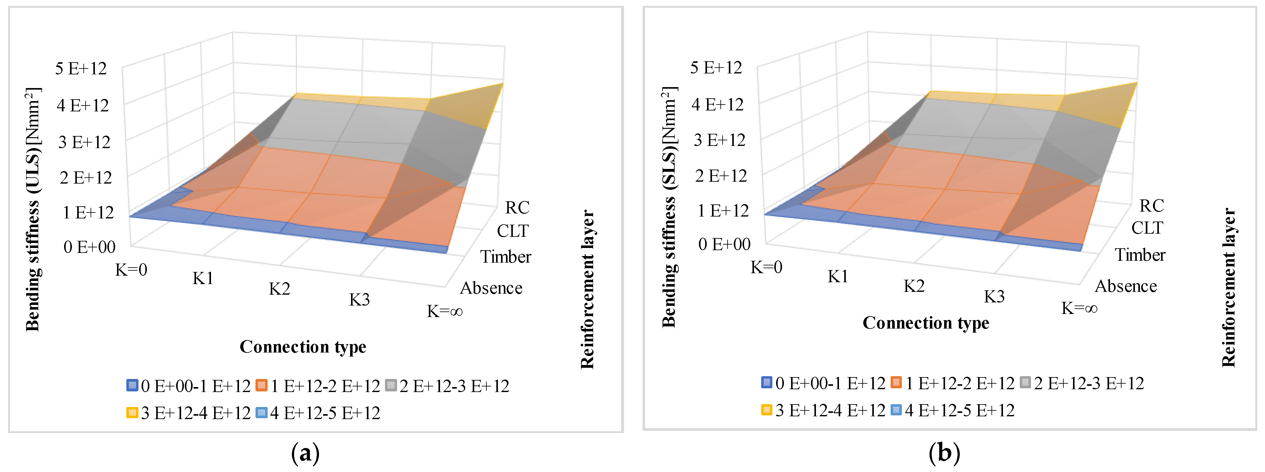
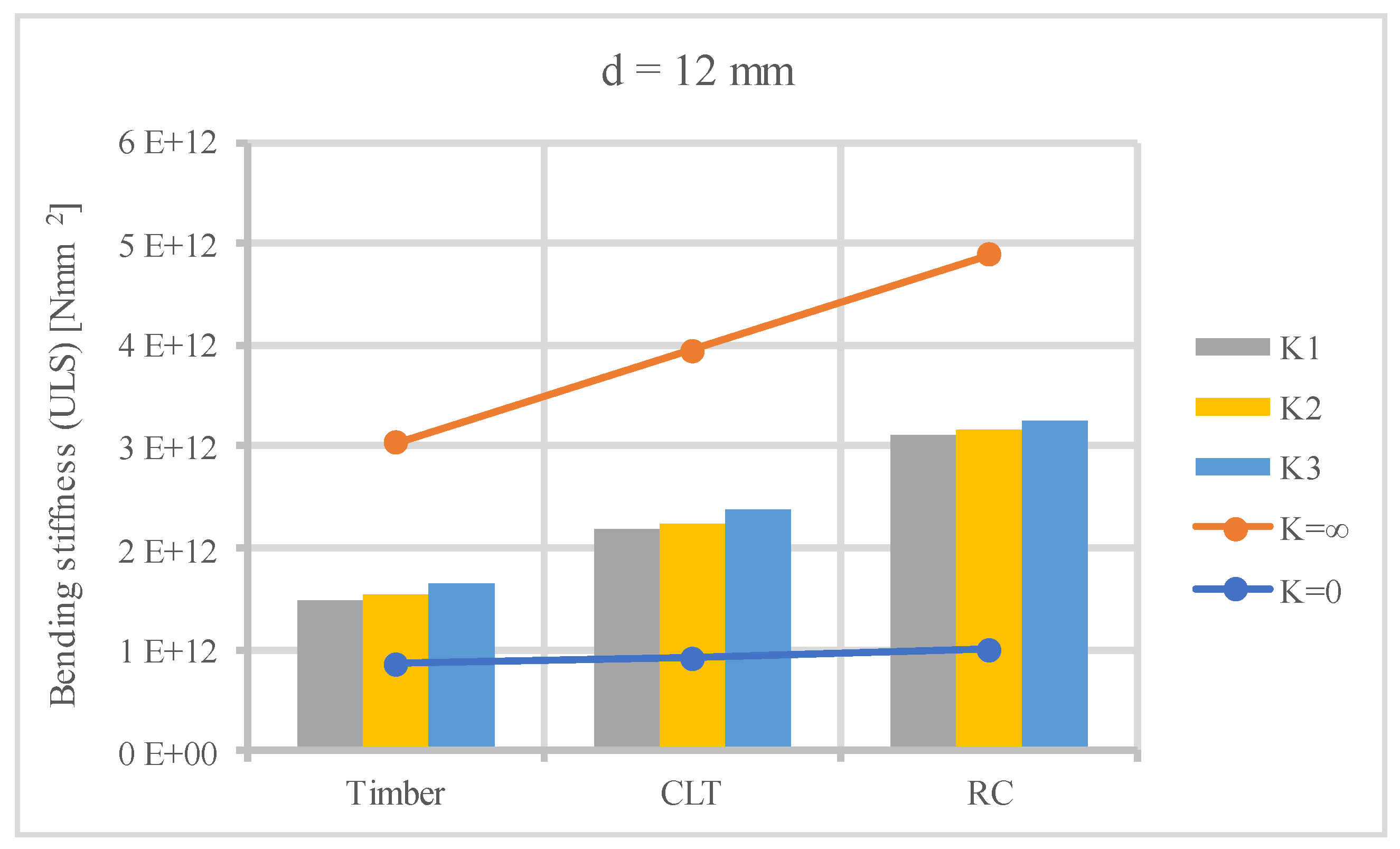
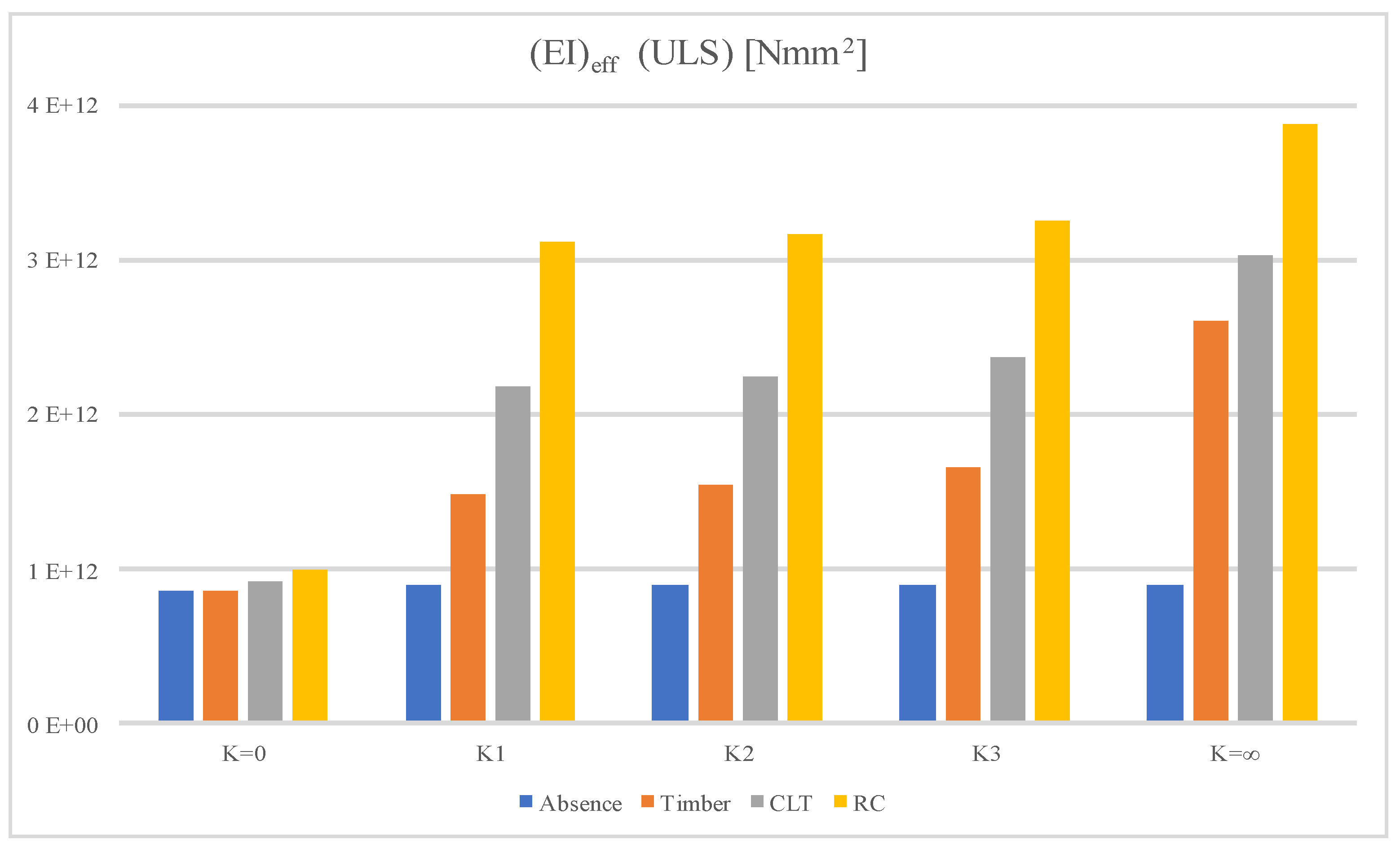
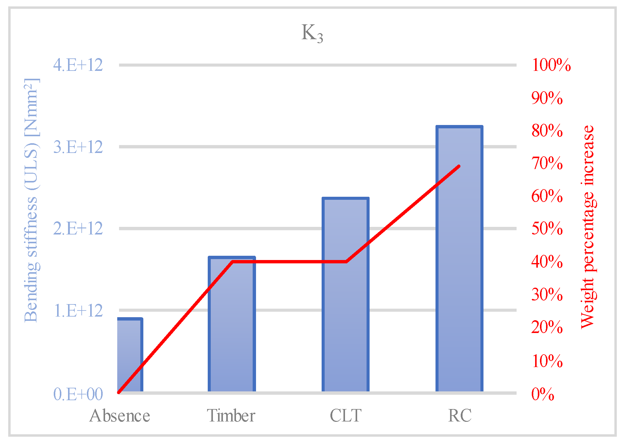
3.3. Bending Stiffness
3.4. Weight
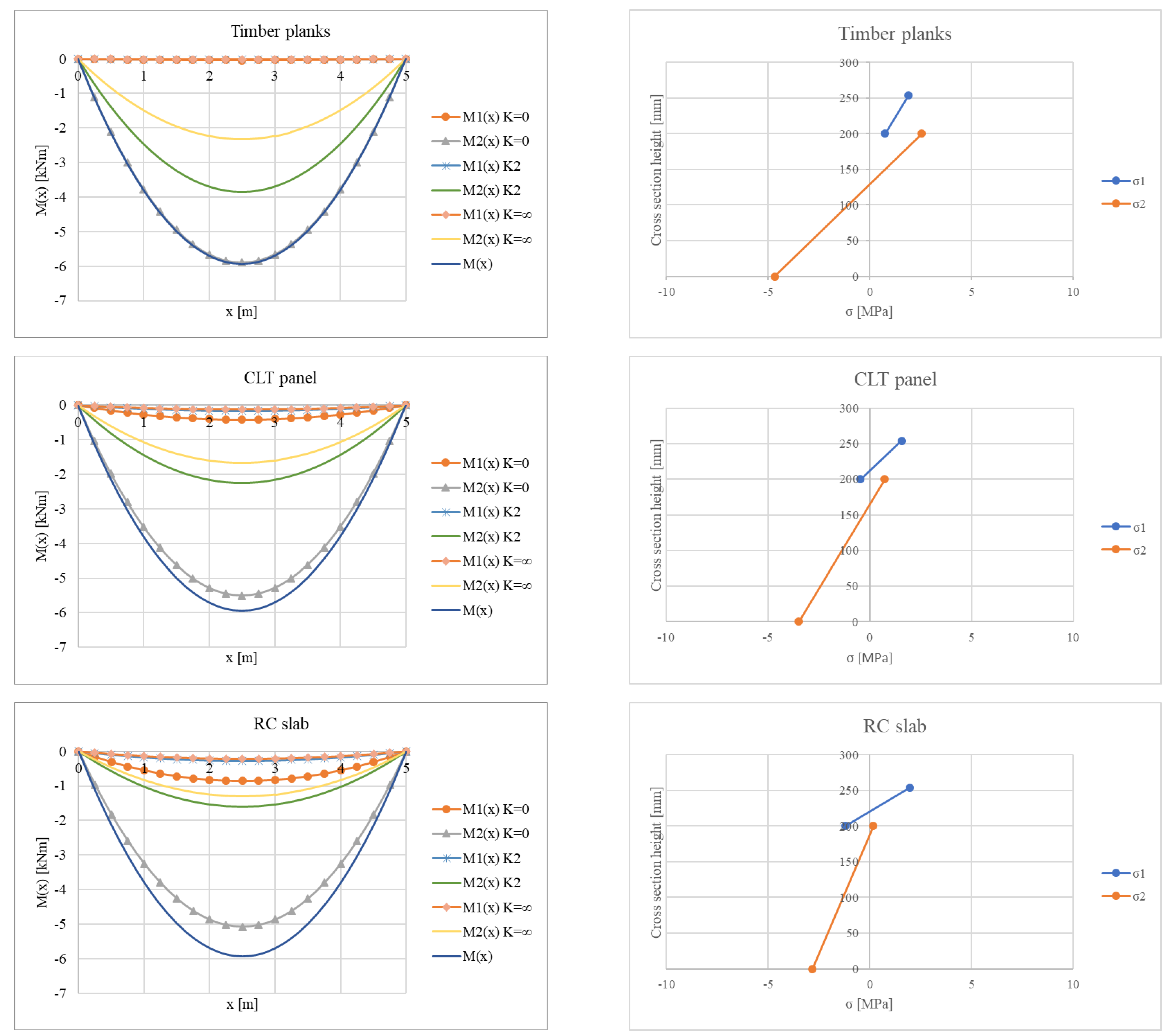
4. Bending Moment and Normal Stresses
5. Conclusions
Author Contributions
Funding
Data Availability Statement
Conflicts of Interest
References
- Branco, J.M.; Kekeliak, M.; Lourenço, P.B. In-plane stiffness of timber floors strengthened with CLT. Eur. J. Wood Wood Prod. 2015, 73, 313–323. [Google Scholar] [CrossRef]
- Gubana, A.; Melotto, M. Efficacy Assessment of Timber Based In-Plane Strengthening of Wooden Floors on the Seismic Response of Masonry Structures by means of DEM Analyses. Procedia Struct. Integr. 2023, 44, 1885–1892. [Google Scholar] [CrossRef]
- Gubana, A. State-of-the-Art Report on high reversible timber to timber strengthening interventions on wooden floors. Constr. Build. Mater. 2015, 97, 25–33. [Google Scholar] [CrossRef]
- Riggio, M.; Tomasi, R.; Piazza, M. Refurbishment of a Traditional Timber Floor with a Reversible Technique: Importance of the Investigation Campaign for Design and Control of the Intervention. Int. J. Arch. Herit. 2014, 8, 74–93. [Google Scholar] [CrossRef]
- Shan, B.; Xiao, Y.; Zhang, W.; Liu, B. Mechanical behavior of connections for glubam-concrete composite beams. Constr. Build. Mater. 2017, 143, 158–168. [Google Scholar] [CrossRef]
- Bedon, C.; Fragiacomo, M. Three-Dimensional Modelling of Notched Connections for Timber–Concrete Composite Beams. Struct. Eng. Int. 2017, 27, 184–196. [Google Scholar] [CrossRef]
- Fragiacomo, M.; Amadio, C.; Macorini, L. Short- and long-term performance of the “Tecnaria” stud connector for timber-concrete composite beams. Mater. Struct. 2007, 40, 1013–1026. [Google Scholar] [CrossRef]
- Bedon, C.; Rajcic, V.; Barbalic, J.; Perkovic, N. CZM-based FE numerical study on pull-out performance of adhesive bonded-in-rod (BiR) joints for timber structures. Structures 2022, 46, 471–491. [Google Scholar] [CrossRef]
- Miotto, J.L.; Dias, A.A. Evaluation of perforated steel plates as connection in glulam–concrete composite structures. Constr. Build. Mater. 2012, 28, 216–223. [Google Scholar] [CrossRef]
- Dias, A.M.P.G.; Kuhlmann, U.; Kudla, K.; Mönch, S.; Dias, A.M.A. Performance of dowel-type fasteners and notches for hybrid timber structures. Eng. Struct. 2018, 171, 40–46. [Google Scholar] [CrossRef]
- Dias, A.; Schänzlin, J.; Dietsch, P. A State-of-the-Art Report by COST Action FP1402/WG 4 Design of Timber-Concrete Composite Structures; Shaker: Maastricht, Germany, 2018. [Google Scholar]
- Angeli, A.; Piazza, M.; Riggio, M.P.; Tomasi, R. Refurbishment of traditional timber floors by means of wood-wood composite structures assembled with inclined screw connectors. In Proceedings of the World Conference on Timber Engineering, Trentino, Italy, 20–24 June 2010. [Google Scholar]
- Corradi, M.; Mustafaraj, E.; Speranzini, E. Sustainability considerations in remediation, retrofit, and seismic upgrading of historic masonry structures. Environ. Sci. Pollut. Res. 2023, 30, 25274–25286. [Google Scholar] [CrossRef]
- Borri, A.; Corradi, M. Architectural Heritage: A Discussion on Conservation and Safety. Heritage 2019, 2, 631–647. [Google Scholar] [CrossRef]
- Lagomarsino, S.; Cattari, S. Seismic Performance of Historical Masonry Structures Through Pushover and Nonlinear Dynamic Analyses. In Perspectives on European Earthquake Engineering and Seismology; Springer: Berlin/Heidelberg, Germany, 2015. [Google Scholar] [CrossRef]
- Anzani, A.; Cardani, G.; Condoleo, P.; Garavaglia, E.; Saisi, A.; Tedeschi, C.; Tiraboschi, C.; Valluzzi, M.R. Understanding of historical masonry for conservation approaches: The contribution of Prof. Luigia Binda to research advancement. Mater. Struct. 2018, 51, 140. [Google Scholar] [CrossRef]
- Unuk, Ž.; Premrov, M.; Leskovar, V. Development of an Innovative Approach for the Renovation of Timber Floors with the Application of CLT Panels and Structural Glass Strips. Int. J. Arch. Herit. 2021, 15, 627–643. [Google Scholar] [CrossRef]
- Tomasi, R.; Crosatti, A.; Piazza, M. Theoretical and experimental analysis of timber-to-timber joints connected with inclined screws. Constr. Build. Mater. 2010, 24, 1560–1571. [Google Scholar] [CrossRef]
- Schiro, G.; Giongo, I.; Sebastian, W.; Riccadonna, D.; Piazza, M. Testing of timber-to-timber screw-connections in hybrid configurations. Constr. Build. Mater. 2018, 171, 170–186. [Google Scholar] [CrossRef]
- De Santis, Y.; Sciomenta, M.; Spera, L.; Rinaldi, V.; Fragiacomo, M.; Bedon, C. Effect of Interlayer and Inclined Screw Arrangements on the Load-Bearing Capacity of Timber-Concrete Composite Connections. Buildings 2022, 12, 2076. [Google Scholar] [CrossRef]
- Nie, Y.; Valipour, H.R. Experimental and analytical study of timber-timber composite (TTC) beams subjected to long-term loads. Constr. Build. Mater. 2022, 342, 128079. [Google Scholar] [CrossRef]
- Chiniforush, A.; Valipour, H.; Ataei, A. Timber-timber composite (TTC) connections and beams: An experimental and numerical study. Constr. Build. Mater. 2021, 303, 124493. [Google Scholar] [CrossRef]
- Aicher, S.; Hirsch, M.; Christian, Z. Hybrid cross-laminated timber plates with beech wood cross-layers. Constr. Build. Mater. 2016, 124, 1007–1018. [Google Scholar] [CrossRef]
- Franke, S. Mechanical properties of beech CLT. In Proceedings of the World Conference on Timber Engineering, Vienna, Austria, 22–25 August 2016. [Google Scholar]
- Crovella, P.; Kurzinski, S. Predicting the Strength and Serviceability Performance of Cross-laminated Timber (CLT) Panels Fabricated with High-Density Hardwood. In Proceedings of the World Conference on Timber Engineering, Santiago, Chile, 9–12 August 2021. [Google Scholar]
- Sciomenta, M.; Spera, L.; Bedon, C.; Rinaldi, V.; Fragiacomo, M.; Romagnoli, M. Mechanical characterization of novel Homogeneous Beech and hybrid Beech-Corsican Pine thin Cross-Laminated timber panels. Constr. Build. Mater. 2021, 271, 121589. [Google Scholar] [CrossRef]
- Li, H.; Wang, L.; Wang, B.J.; Wei, Y. Study on in-plane compressive performance of cross-laminated bamboo and timber (CLBT) wall elements. Eur. J. Wood Wood Prod. 2022, 81, 343–355. [Google Scholar] [CrossRef]
- Concu, G.; De Nicolo, B.; Fragiacomo, M.; Trulli, N.; Valdes, M.; Dupray, S.; Simm, J.; Williams, J.; Kuna, K.; Airey, G.; et al. Grading of maritime pine from Sardinia (Italy) for use in cross-laminated timber. Proc. Inst. Civ. Eng.-Constr. Mater. 2018, 171, 11–21. [Google Scholar] [CrossRef]
- Wang, T.; Wang, Y.; Crocetti, R.; Wålinder, M.; Bredesen, R.; Blomqvist, L. Adhesively bonded joints between spruce glulam and birch plywood for structural applications: Experimental studies by using different adhesives and pressing methods. Wood Mater. Sci. Eng. 2023, 18, 1141–1150. [Google Scholar] [CrossRef]
- EN 1995-1-1; Eurocode 5: Design of Timber Structures—Part 1-1: General—Common Rules and Rules for Buildings. European Committee for Standardization: Brussels, Belgium, 2004.
- Bedon, C.; Sciomenta, M.; Fragiacomo, M. Correlation approach for the Push-Out and full-size bending short-term performances of timber-to-timber slabs with Self-Tapping Screws. Eng. Struct. 2021, 238, 112232. [Google Scholar] [CrossRef]
- Jeong, G.Y.; Pham, V.S.; Tran, D.K. Development of predicting equations for slip modulus and shear capacity of CLT–concrete composite with screw connections. J. Build. Eng. 2023, 71, 106468. [Google Scholar] [CrossRef]
- Denouwé, D.D.; Messan, A.; Fournely, E.; Bouchair, A. Influence of Interlayer in Timber-Concrete Composite Structures with Threaded Rebar as Shear Connector-Experimental Study. Am. J. Civ. Eng. Arch. 2018, 6, 38–45. [Google Scholar] [CrossRef]
- DRAFT prEN 1995-1-1; Eurocode 5—Design of Timber Structures—Part 1-1: General Rules and Rules for Buildings. European Committee for Standardization: Brussels, Belgium, 2023.
- Unuk, Ž.; Leskovar, V.Ž.; Premrov, M. Timber Floors and Strengthening Techniques (Illustrated with a Numerical Example). Tek. Dergi 2019, 30, 9261–9288. [Google Scholar] [CrossRef]


| Reinforcing System | d = 8 mm | d = 10 mm | d = 12 mm | |||
|---|---|---|---|---|---|---|
| Kser [N/mm] | Ku [N/mm] | Kser [N/mm] | Ku [N/mm] | Kser [N/mm] | Ku [N/mm] | |
| (i) Timber/(ii) CLT | 3712 | 2475 | 4640 | 3093 | 5568 | 3712 |
| (iii) RC | 5444 | 3630 | 6805 | 4537 | 8167 | 5444 |
| Reinforcing System | (EI)0 [Nmm2] | (EI)∞ [Nmm2] |
|---|---|---|
| None | 8.54 × 10¹¹ | 8.95 × 10¹¹ |
| (i) Timber plank | 8.62 × 10¹¹ | 2.60 × 10¹² |
| (ii) CLT panel | 9.19 × 10¹¹ | 3.03 × 10¹² |
| (iii) RC slab | 9.98 × 10¹¹ | 3.88 × 10¹² |
| Reinforcing System | d = 8 mm | d = 10 mm | d = 12 mm | |||
|---|---|---|---|---|---|---|
| γ1 (SLS) [-] | γ1 (ULS) [-] | γ1 (SLS) [-] | γ1 (ULS) [-] | γ1 (SLS) [-] | γ1 (ULS) [-] | |
| (i) Timber | 0.38 | 0.29 | 0.44 | 0.34 | 0.48 | 0.38 |
| (ii) CLT | 0.24 | 0.17 | 0.28 | 0.21 | 0.32 | 0.24 |
| (iii) RC | 0.17 | 0.12 | 0.20 | 0.15 | 0.24 | 0.17 |
| Reinforcing System | (EI)eff [Nmm2] | ||||||||
|---|---|---|---|---|---|---|---|---|---|
| K1 | K2 | K3 | |||||||
| d = 8 mm | d = 10 mm | d = 12 mm | d = 8 mm | d = 10 mm | d = 12 mm | d = 8 mm | d = 10 mm | d = 12 mm | |
| None | 8.93 × 10¹¹ | 8.93 × 10¹¹ | 8.94 × 10¹¹ | ||||||
| (i) Timber | 1.42 × 10¹² | 1.45 × 10¹² | 1.48 × 10¹² | 1.47 × 10¹² | 1.51 × 10¹² | 1.54 × 10¹² | 1.57 × 10¹² | 1.61 × 10¹² | 1.65 × 10¹² |
| (ii) CLT | 2.13 × 10¹² | 2.16 × 10¹² | 2.19 × 10¹² | 2.18 × 10¹² | 2.22 × 10¹² | 2.25 × 10¹² | 2.28 × 10¹² | 2.33 × 10¹² | 2.37 × 10¹² |
| (iii) RC | 3.09 × 10¹² | 3.11 × 10¹² | 3.12 × 10¹² | 3.12 × 10¹² | 3.14 × 10¹² | 3.16 × 10¹² | 3.19 × 10¹² | 3.22 × 10¹² | 3.25 × 10¹² |
| Reinforcing System | (EI)eff [Nmm2] | ||||||||
|---|---|---|---|---|---|---|---|---|---|
| K1 | K2 | K3 | |||||||
| d = 8 mm | d = 10 mm | d = 12 mm | d = 8 mm | d = 10 mm | d = 12 mm | d = 8 mm | d = 10 mm | d = 12 mm | |
| None | 8.93 × 10¹¹ | 8.93 × 10¹¹ | 8.94 × 10¹¹ | ||||||
| (i) Timber | 1.48 × 10¹² | 1.51 × 10¹² | 1.54 × 10¹² | 1.54 × 10¹² | 1.58 × 10¹² | 1.61 × 10¹² | 1.65 × 10¹² | 1.69 × 10¹² | 1.72 × 10¹² |
| (ii) CLT | 2.19 × 10¹² | 2.22 × 10¹² | 2.25 × 10¹² | 2.25 × 10¹² | 2.29 × 10¹² | 2.33 × 10¹² | 2.37 × 10¹² | 2.43 × 10¹² | 2.47 × 10¹² |
| (iii) RC | 3.12 × 10¹² | 3.15 × 10¹² | 3.17 × 10¹² | 3.16 × 10¹² | 3.19 × 10¹² | 3.22 × 10¹² | 3.25 × 10¹² | 3.29 × 10¹² | 3.33 × 10¹² |
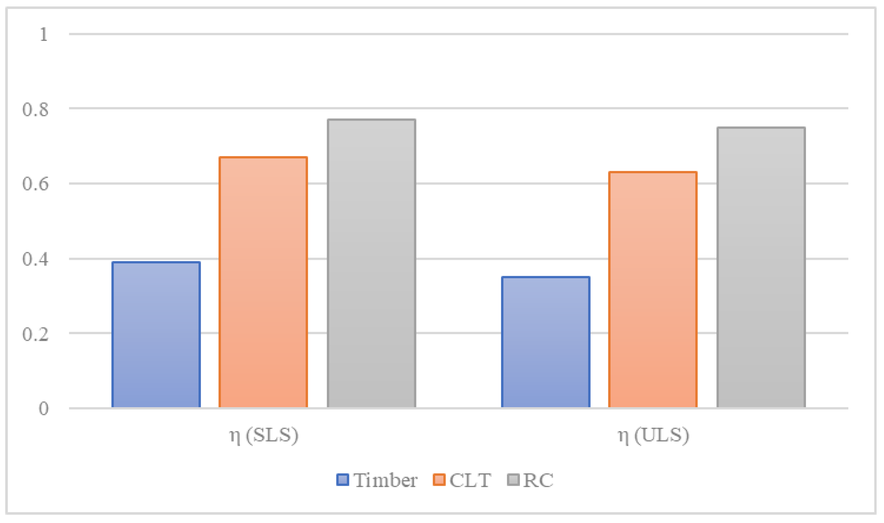
| Reinforcing System | d = 8 mm | d = 10 mm | d = 12 mm | |||
|---|---|---|---|---|---|---|
| η (SLS) [-] | η (ULS) [-] | η (SLS) [-] | η (ULS) [-] | η (SLS) [-] | η (ULS) [-] | |
| (i) Timber | 0.39 | 0.35 | 0.41 | 0.37 | 0.43 | 0.39 |
| (ii) CLT | 0.63 | 0.60 | 0.65 | 0.61 | 0.67 | 0.63 |
| (iii) RC | 0.75 | 0.74 | 0.76 | 0.74 | 0.77 | 0.75 |
Disclaimer/Publisher’s Note: The statements, opinions and data contained in all publications are solely those of the individual author(s) and contributor(s) and not of MDPI and/or the editor(s). MDPI and/or the editor(s) disclaim responsibility for any injury to people or property resulting from any ideas, methods, instructions or products referred to in the content. |
© 2024 by the authors. Licensee MDPI, Basel, Switzerland. This article is an open access article distributed under the terms and conditions of the Creative Commons Attribution (CC BY) license (https://creativecommons.org/licenses/by/4.0/).
Share and Cite
Spera, L.; Sciomenta, M.; Bedon, C.; Fragiacomo, M. Out-of-Plane Strengthening of Existing Timber Floors with Cross Laminated Timber Panels Made of Short Supply Chain Beech. Buildings 2024, 14, 749. https://doi.org/10.3390/buildings14030749
Spera L, Sciomenta M, Bedon C, Fragiacomo M. Out-of-Plane Strengthening of Existing Timber Floors with Cross Laminated Timber Panels Made of Short Supply Chain Beech. Buildings. 2024; 14(3):749. https://doi.org/10.3390/buildings14030749
Chicago/Turabian StyleSpera, Luca, Martina Sciomenta, Chiara Bedon, and Massimo Fragiacomo. 2024. "Out-of-Plane Strengthening of Existing Timber Floors with Cross Laminated Timber Panels Made of Short Supply Chain Beech" Buildings 14, no. 3: 749. https://doi.org/10.3390/buildings14030749