1. Introduction
Single-story steel structure factories, especially those constructed with lightweight portal frames, are widely used in China due to their low cost, reduced weight, and shorter construction periods [
1]. However, the prevalent structural design approach for such buildings remains two-dimensional (2D), a practice driven by historical preferences, resulting in final designs typically depicted in planar CAD drawings [
2]. This conventional design approach omits a three-dimensional (3D) perspective, potentially increasing the risk of design inaccuracies and subsequent revisions [
3]. In addition, the traditional two-dimensional design workflow often segregates disciplines such as architectural, structural, and MEP, leading to poor coordination, thereby impacting the overall quality and efficiency of the finished project.
BIM, as a continuously evolving advanced digital technology and process, has been triggering a sustained revolutionary impact on the architecture, engineering, and construction (AEC) industry [
4,
5,
6]. Unlike the static 2D drawings, BIM models are dynamic, serving as a relational database that stores all information regarding building objects throughout their lifecycle. This comprehensive repository of data supports informed decision-making throughout the entire project lifecycle, from initial design to final demolition [
7].
In the design phase, BIM technology allows designers to transition from traditional 2D design to 3D parametric design. This transition not only enhances the accuracy and speed of design processes but also fosters improved collaboration and facilitates integrated project delivery [
8,
9,
10]. Single-story steel structure factories have highly similar structural components and layouts. This uniformity makes them particularly well suited to the application of BIM technology for the generation of 3D models and the automation of design processes.
The application of BIM technology during the design of single-story steel structure factories involves two challenges. Firstly, the existing BIM modeling tools do not adequately support the automatic generation of models for this type of structure, leading to inefficiencies in the modeling process. Secondly, most BIM software possesses excellent 3D modeling and visualization capabilities, but often lacks structural calculation functions [
11,
12]. Consequently, when applying BIM models to structural calculation and analysis, it is common practice to import the BIM model into professional finite element software via data exchange. Although the Industry Foundation Classes (IFC) format used for data exchange was designed to maintain a comprehensive dataset of BIM information [
13], issues with information loss still arise during the data transfer process [
14,
15]. Designers are compelled to manually correct any missing or erroneous data, which reduces design efficiency and increases labor costs.
Although the previous studies have explored the above two challenges and proposed some solutions to apply BIM technology in the field of steel structures, there is a conspicuous absence of an integrated software platform and a complete design workflow specifically for the design of single-story steel structure factories.
Therefore, the purpose of this study is to develop a BIM platform for the design of single-story steel structure factories. This platform integrates Revit 2018, SQL Server 2019, and SAP2000 v23 software for modeling, data exchange, and structural analysis. Firstly, using the C# programming language and the Revit 2018 API, the platform enabled the automated generation of BIM models, as well as the application and combination of loads. Furthermore, a specialized SQL Server database was developed for data exchange, and the SAP2000 OAPI was utilized for structural calculation and analysis. In addition, the platform enabled the display of internal force results within the Revit environment. By using this platform, designers can perform structural design and optimization more efficiently, ensuring the precision and reliability of their design projects.
2. Literature Review
BIM technology has been widely applied in the field of steel structures, with many researchers developing specialized tools and methods. Wei et al. [
16] developed a 3D software system called SteelGate, which was constructed by using the object-oriented design method. It included a parametric database for structural elements such as steel panels and beams, equipped with tools for structural analysis and generation of construction drawings. While highly effective for steel gate design, the software may be less applicable to other structural forms. A web-based platform developed by Chen et al. [
17] was specifically engineered for the manufacturing phase of steel structures, addressing common issues such as production delays and quality inconsistencies. However, it is important to note that the platform did not extend its capabilities to the earlier stages of structural design and analysis, which were critical for the overall engineering process. Moreover, Carroll et al. [
18] utilized the visual programming language Dynamo to automate repetitive tasks in the steel structure design process, specifically focusing on the generation of BIM and an analysis model. Laefer et al. [
19] proposed a method to employ kernel density estimation for determining the shape and section size of steel structure components from point cloud data, which helped to generate geometry in a BIM-compatible format. Yang et al. [
20] provided an approach for the retrieval of geometric details from laser-scanned data of steel structures, facilitating the automated development of an as-built BIM model. Basta et al. [
21] established an equation model for Steel Structure Deconstructability Assessment Scoring (SS-DAS), and Dynamo was utilized to create a BIM-based framework to assess steel structure deconstructability. Avendaño et al. [
22] designed an integrated BIM model for steel structure construction projects, aimed at providing systematic, efficient, and precise guidance during the construction of steel structures. Yoo et al. [
23] compared the efficiency of using 2D drawings versus 3D models during the design and manufacturing stages of steel structures, and they analyzed the advantages of using 3D models quantitatively.
Interoperability in BIM is the capability of different software applications to communicate and exchange data efficiently and accurately [
24], which is a critical factor for the application of BIM in structural design. The literature review by Vilutiene et al. [
25] demonstrated that there has been a significant increase in the volume of research concerning the application of BIM in structural design since 2014. Nevertheless, when compared to the application of BIM in other domains, the quantity of studies pertinent to structural design remains comparatively low. Additionally, their findings suggest that recent research themes in structural design are intimately associated with interoperability. Shin et al. [
26] emphasized the dependence of structural quality on interoperability, which can be realized through openBIM platforms or application-programming interfaces. Musella et al. [
27] utilized an openBIM platform based on the standard data format IFC to manage existing structures before and after seismic events. Gerbino et al. [
28] examined CAD-CAE interoperability issues and developed mechanisms for bidirectional data exchange between AEC CAD/CAE software to establish a baseline for data exchange. Tang et al. [
12] constructed a data conversion interface between BIM software and the finite analysis software ABAQUS. The interface enables BIM modeling data to be interoperable with finite element analysis software to realize structural calculation within BIM. Despite these advancements, the goal of perfectly interoperable integrated systems remains elusive [
29]. Researchers continue to seek more efficient implementations of BIM by developing high-performance tools, enhancing interactions, and optimizing processes under different conditions [
30].
While some studies have explored the application of BIM in the domain of steel structures and its interoperability within structural design, there remains a lack of a software platform integrating the functions of BIM modeling and structural analysis specifically for single-story steel structure factories.
3. Methodology
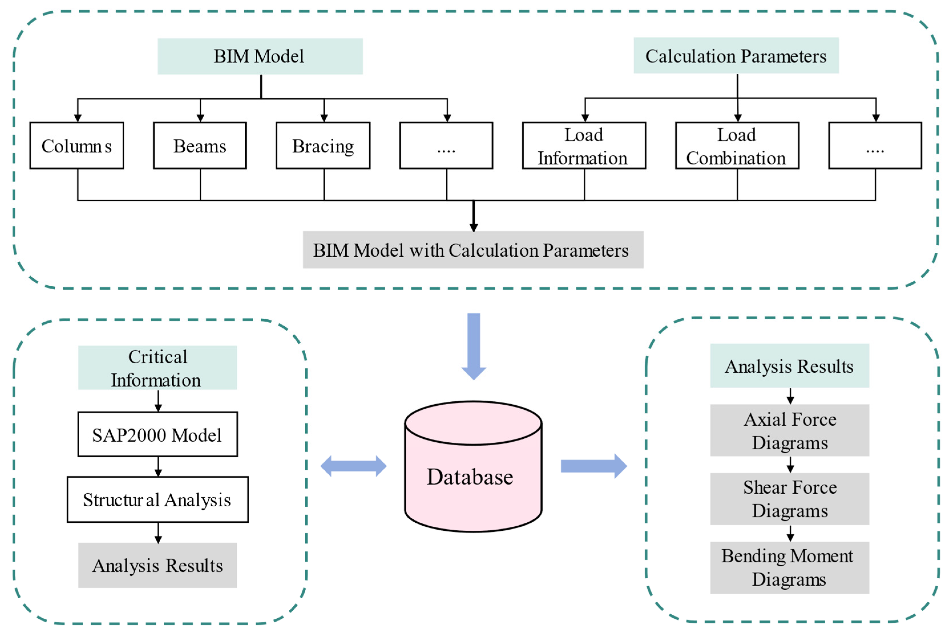
In this paper, the design process for single-story steel structure factories was optimized by developing a dedicated BIM platform. This platform integrates Revit 2018, SQL Server 2019, and SAP2000 v23 software, enabling the automatic generation of BIM models, the application of loads, structural calculations, and the visualization of internal forces. The framework of the developed platform is illustrated in
Figure 1 and described below:
BIM model auto-generation: Leveraging Revit secondary development technology, the platform automatically constructed a BIM model of a single-story steel structure factory based on parameters entered by the designer. This model included all critical structural elements, such as columns, beams, and bracing.
Setting calculation parameters: Once the BIM model was constructed, the platform generated appropriate loads and load combinations based on the structural calculation parameters set by the designer.
Structural calculation and analysis: The geometric information and structural parameters of the BIM model were transferred to a specialized database. Utilizing the SAP2000 OAPI, the platform automatically created an SAP2000 model and ran the analysis. The analysis results were subsequently stored in the database for review, verification, and as part of the project’s documentation.
Internal force visualization: The platform utilized the internal force results stored in the database, employing Dynamo–Revit API hybrid programming, to render internal force diagrams within the Revit environment. These diagrams enabled designers to conduct in-depth analysis and verification of the structural elements.
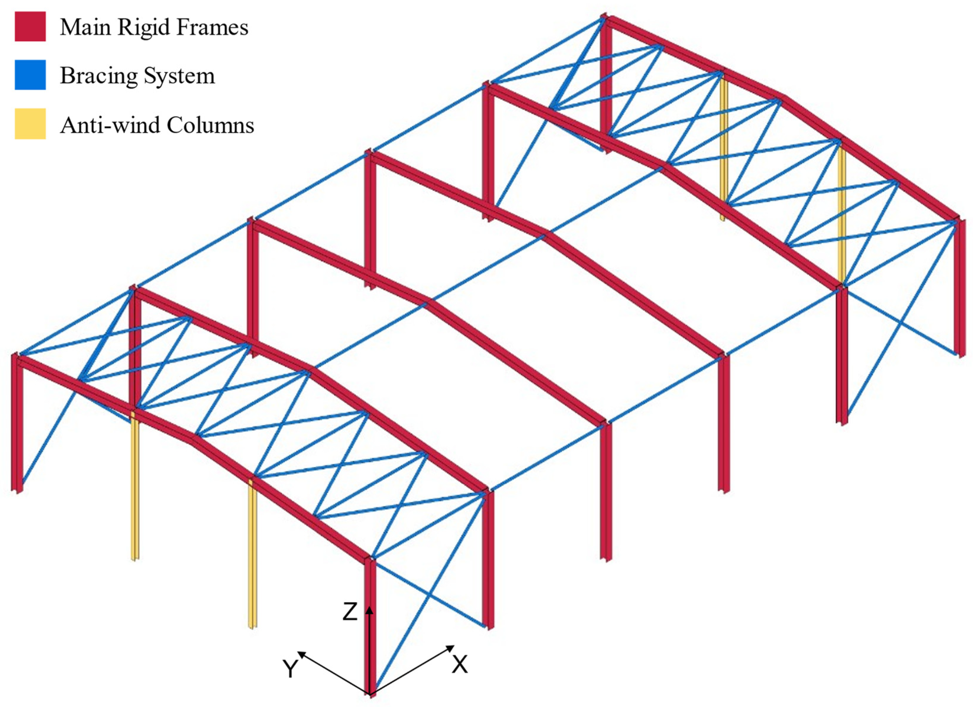
3.1. Generation of the BIM Model
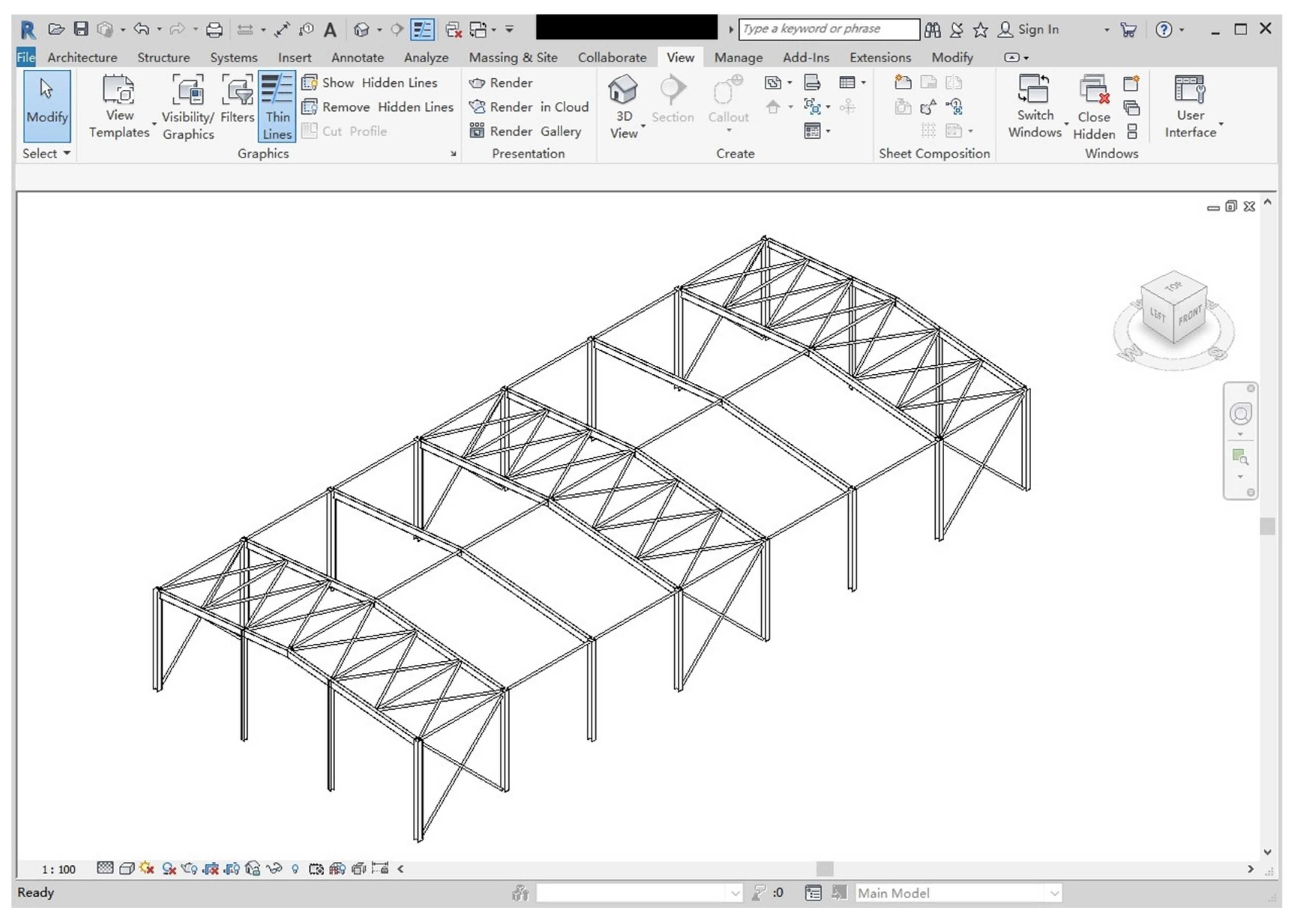
The BIM model of a single-story steel structure factory was automatically generated using Revit secondary development technology. This automation was driven by designer-specified parameters, such as bay width, spacings, materials, and section types. The portal frame structure is the most commonly used system for single-story steel structure factories in China. The primary structural components of this type of factory include the main frames, the bracing system, and the anti-wind columns. The target model generated is shown in
Figure 2.
3.1.1. Generation of Main Frames
The main frames, consisting of columns and beams, provide the basic load-bearing capacity for the entire structure. The basic approach to automating the generation of columns using the Revit API is as follows:
Invoke the Create.NewFamilyInstance() method to create column instances based on specified parameters.
Access the parameters of the column instances that need to be modified using the element.get_Parameter() method, and then adjust these parameters using the set() method.
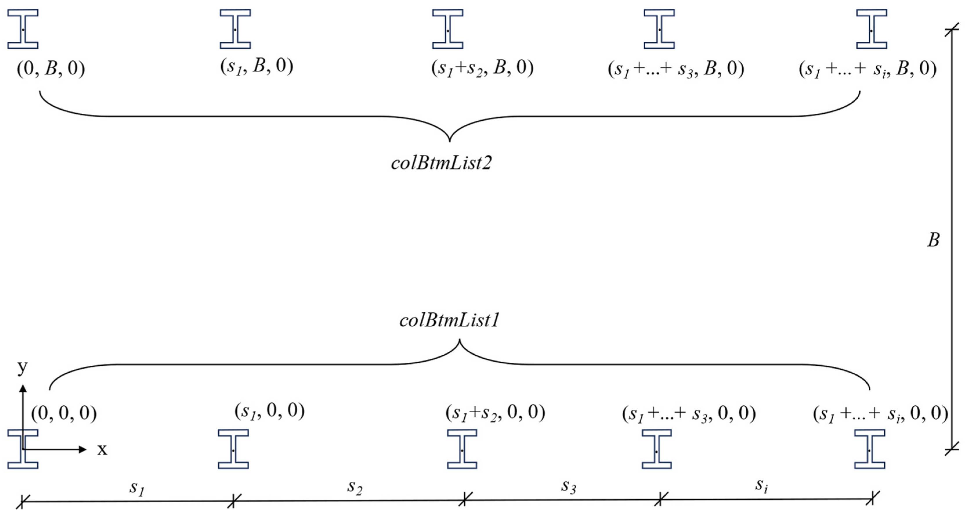
During the column creation process, the key method Create.NewFamilyInstance() involves four parameters: location, symbol, level, and structuralType. The symbol was obtained based on the designer’s selection of the column type or family symbol from the Revit library. The level was set to the base of level in the Revit environment. The structuralType was determined by the nature of the components. For columns, this was set to StructuralType.Column. Thus, only the location, an XYZ point that defines the physical placement of the column, needed to be calculated based on the bay width and spacings. As depicted in
Figure 3,
B denotes the bay width of the portal frame, and
denotes the spacing for the
i-th span of the frame. Two Lists,
colBtmList1 and
colBtmList2, were utilized to store the base coordinates of the columns on both sides of the portal frame. The index of the List represents the span number of the frame. The count of the List represents the total number of frames. In
colBtmList1 and
colBtmList2, the Z-coordinate values for all location points were set to 0. For location points in
colBtmList1, the Y-coordinate values were set to 0; for those in
colBtmList2, the Y-coordinate values were set to
B. The X-coordinate values in
colBtmList1 and
colBtmList2 were calculated by cumulatively adding the spacings
. Following the creation of the initial column model, the material properties and top elevation of the columns were adjusted by design requirements.
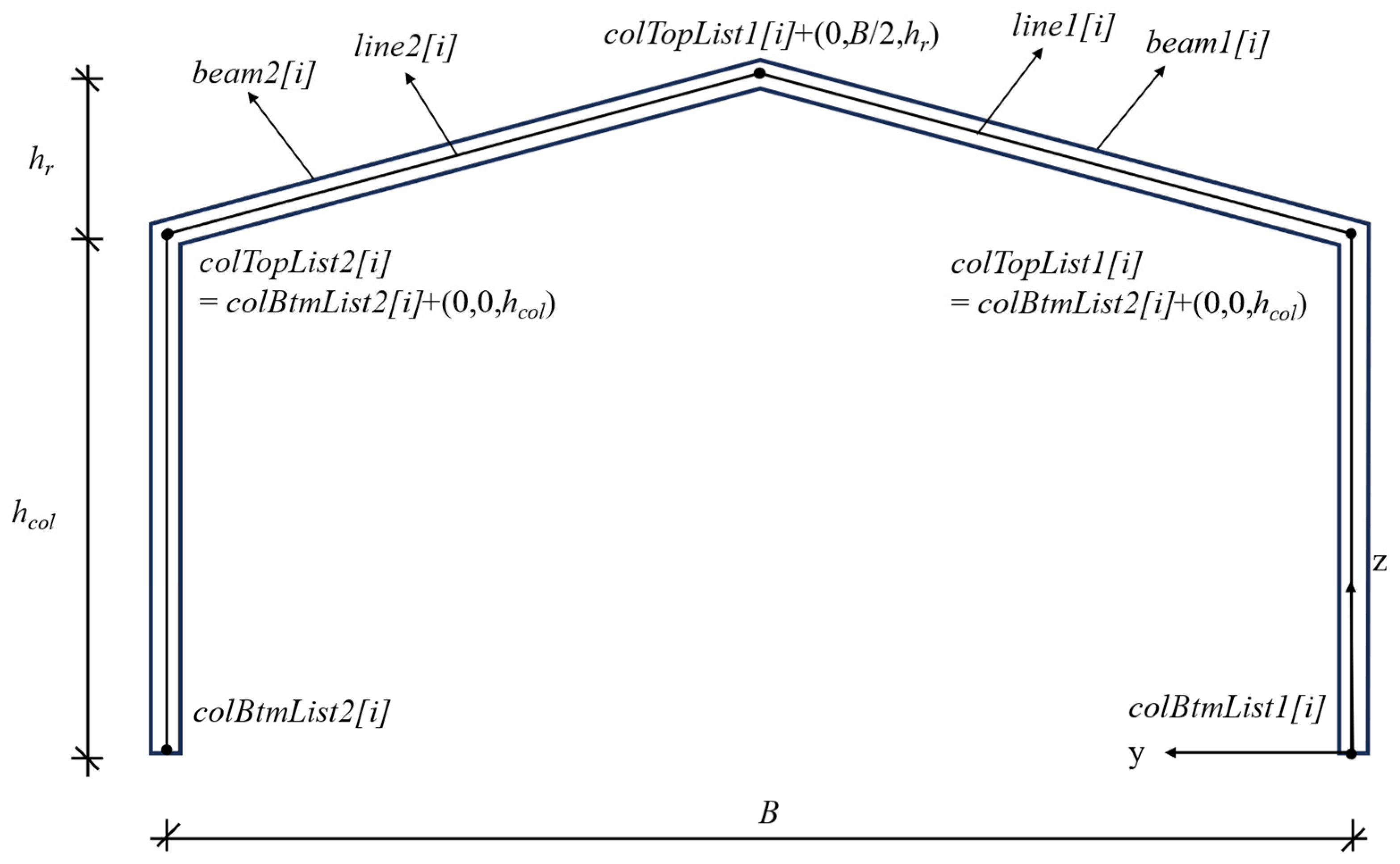
In contrast to column generation, which was based on a single location point, beam generation relies on a location curve. The steps for beam generation using Revit API are as follows:
Calculate the start and end coordinates of the beam by vector addition, using the column height and the roof height input by the designer.
Use the Line.CreateBound() method to create a location line based on the calculated coordinates of the two endpoints.
Invoke the Create.NewFamilyInstance() method, passing the established location line as a parameter to generate the beam instance.
Adjust the beam instance parameters, using the element.get_Parameter() method followed by the set() method for necessary modifications.
As demonstrated in
Figure 4,
colBtmList[
i] (
colBtmList1[
i] and
colBtmList2[
i]) represents the base coordinate of the column in the
i-th span frame,
is the column’s height, and
is the height of the roof. The two endpoints for
Line1[
i] and
Line2[
i] can be calculated as follows:
Based on the endpoint coordinates calculated above, we used Line.CreateBound() to generate the location lines that define the beam axes, and then passed these lines as parameters to the Create.NewFamilyInstance() method to generate the beam instances in Revit. Similar to the generation of columns, after the beam instances were generated, the material properties of the beams also needed to be adjusted.
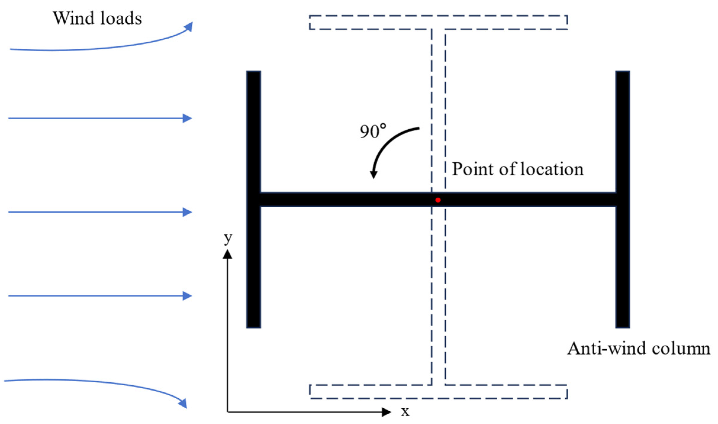
3.1.2. Generation of Anti-Wind Columns
The procedure for generating anti-wind columns was similar to the process for columns detailed in
Section 3.1.1. The difference for anti-wind columns lay in an additional step—rotating the columns by 90 degrees within the XY plane to ensure their cross-sections were appropriately oriented to resist wind loads. In the Revit API, the ElementTransformUtils class offers the RotateElement() method, which facilitates the rotation of elements. As depicted in
Figure 5, the rotation axis was a line object that was perpendicular to the XY plane and passed through the midpoint of the column, extending in the direction of the
Z-axis. It is important to note that the rotation angle must be expressed in radians, with 90 degrees being equivalent to π/2 radians.
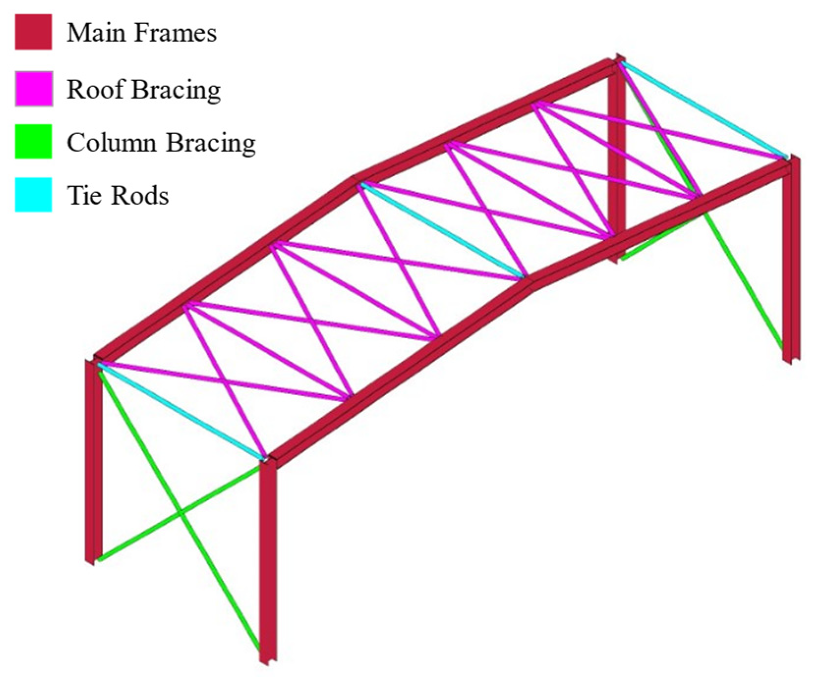
3.1.3. Generation of Bracing System
The bracing system includes tie rods, column bracing, and roof bracing. Tie rods are typically arranged along the full length of the structure at the top of the columns and at the ridge. Column bracing and roof bracing are commonly positioned within the same span, and they are usually implemented in a cross-bracing pattern to enhance structural stability.
The generation of bracing elements followed a methodology similar to that described for beams in
Section 3.1.1. The critical aspect was accurately acquiring the coordinates at both ends of the bracing elements. For tie rods, the end coordinates were derived from the column top or ridge coordinates of the adjacent frames. For column bracing, the end coordinates were determined by the column bottom coordinates and the column top coordinates of the adjacent frame. For roof bracing, it was imperative to perform calculations based on the specified number of roof braces to ensure an even distribution. Algorithm 1 provides the essential code for calculating the end coordinates of the roof bracing and generating the corresponding model.
Figure 6 shows the generated bracing system in Revit 2018.
Through the methodology presented above, the developed platform can rapidly construct the BIM model of a single-story steel structure factory as shown in
Figure 2. It is a shift from manual to automated modeling, significantly improving modeling efficiency.
| Algorithm 1: Generate the roof bracing using the Revit API |
| Require: colTopList containing column top coordinates, rofTopList containing roof top coordinates, n represents number of roof bracings, symbol represents FamilySymbol in the Revit API, level represents Reference Level in the Revit API. |
| 1 | if need to generate roof bracing in the i-th span then |
| 2 | for j = 0 to n do |
| 3 | start←colTopList[i] + j/n*(rofTopList[i] − colTopList[i]); |
| 4 | end←colTopList[i + 1] + (j + 1)/n*(rofTopList[i + 1] − colTopList[i + 1]); |
| 5 | line1←Line.CreateBound(start, end); |
| 6 | doc.Create.NewFamilyInstance(line1, symbol, level, StructuralType.Bracing); |
| 7 | end for |
| 8 | for j = 0 to n − 1 do |
| 9 | start←colTopList[i + 1] + j/n*(rofTopList[i + 1] − colTopList[i + 1]); |
| 10 | end←colTopList[i] + (j + 1)/n*(rofTopList[i] − colTopList[i]); |
| 11 | line2←Line.CreateBound(start, end); |
| 12 | doc.Create.NewFamilyInstance(line2, symbol, level, StructuralType.Bracing); |
| 13 | end for |
| 14 | end if |
3.2. Generation of Load Case, Load, and Load Combination
Based on the generated BIM model, load cases, loads, and load combinations were generated by using the Revit API, in accordance with the Chinese load standards.
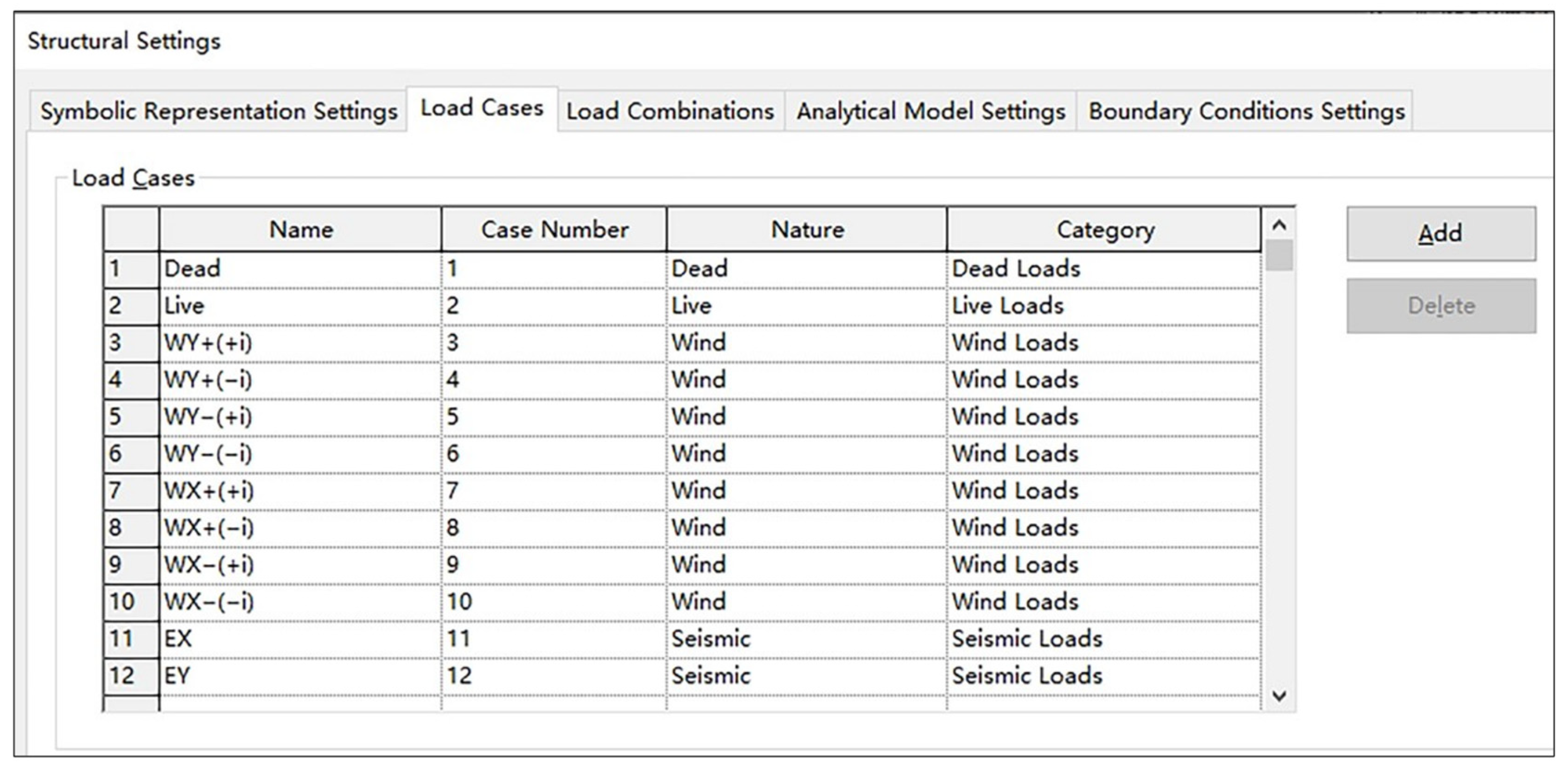
3.2.1. Generation of Load Case
When designing a single-story steel structure factory, the load cases typically include dead load case, live load case, wind load case, seismic load case, and others, depending on the specific project. These load cases could be defined by utilizing the LoadCase.Create() method. Once these load cases were defined, the designer could view and manage them through the Load Cases tab in Revit 2018, as shown in
Figure 7.
3.2.2. Generation of Load
In order to accurately apply loads in the Revit analysis model, it was crucial to convert area loads into equivalent line loads. The equivalence formulas for dead loads and live loads are as follows:
where
denotes the nominal value of dead load (kN/m
2),
denotes the nominal value of live load (kN/m
2), and
denotes the loaded width (m).
The equivalence formula for wind loads is as follows:
where
denotes the nominal value of wind load (kN/m
2),
denotes the basic wind pressure (kN/m
2),
denotes the wind load coefficient, and
is the coefficient for variation of wind pressure with height.
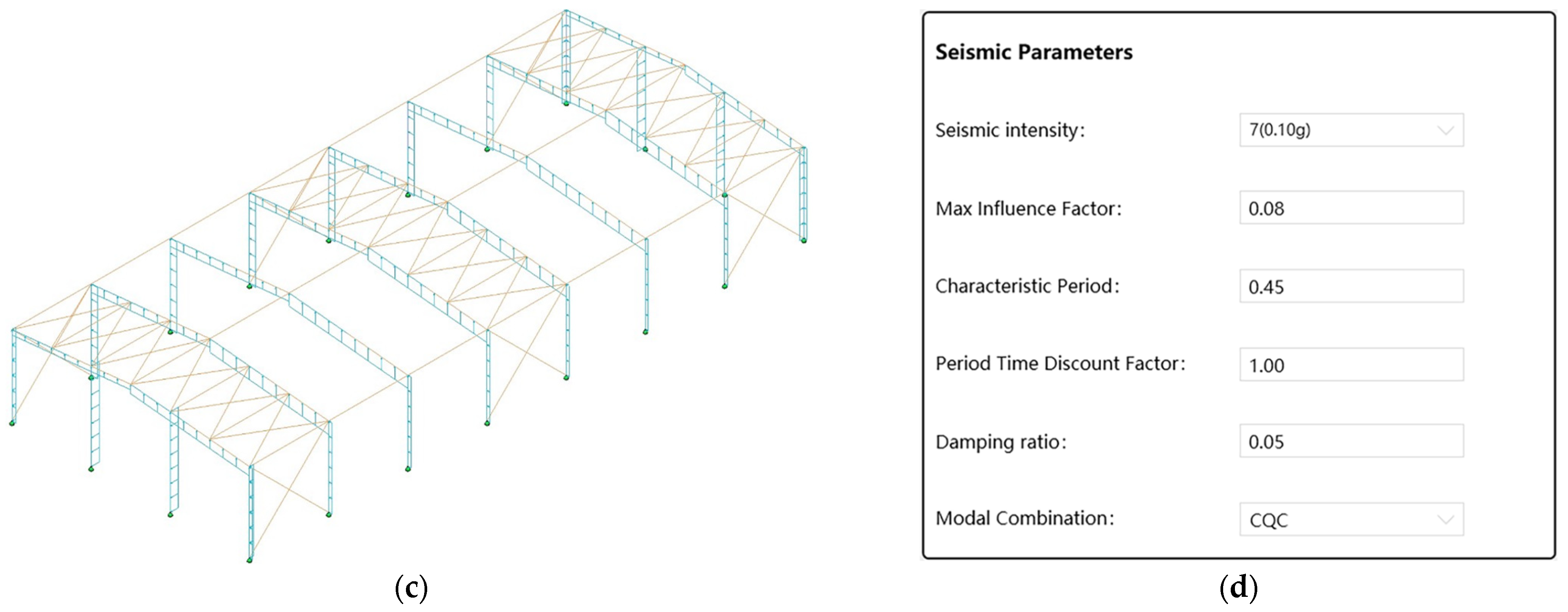
The steps to generate the loads are as follows:
The critical parameters for seismic analysis, such as seismic intensity, characteristic period, and damping ratio, were input by the designers into the platform interface. These parameters were then stored in the database.
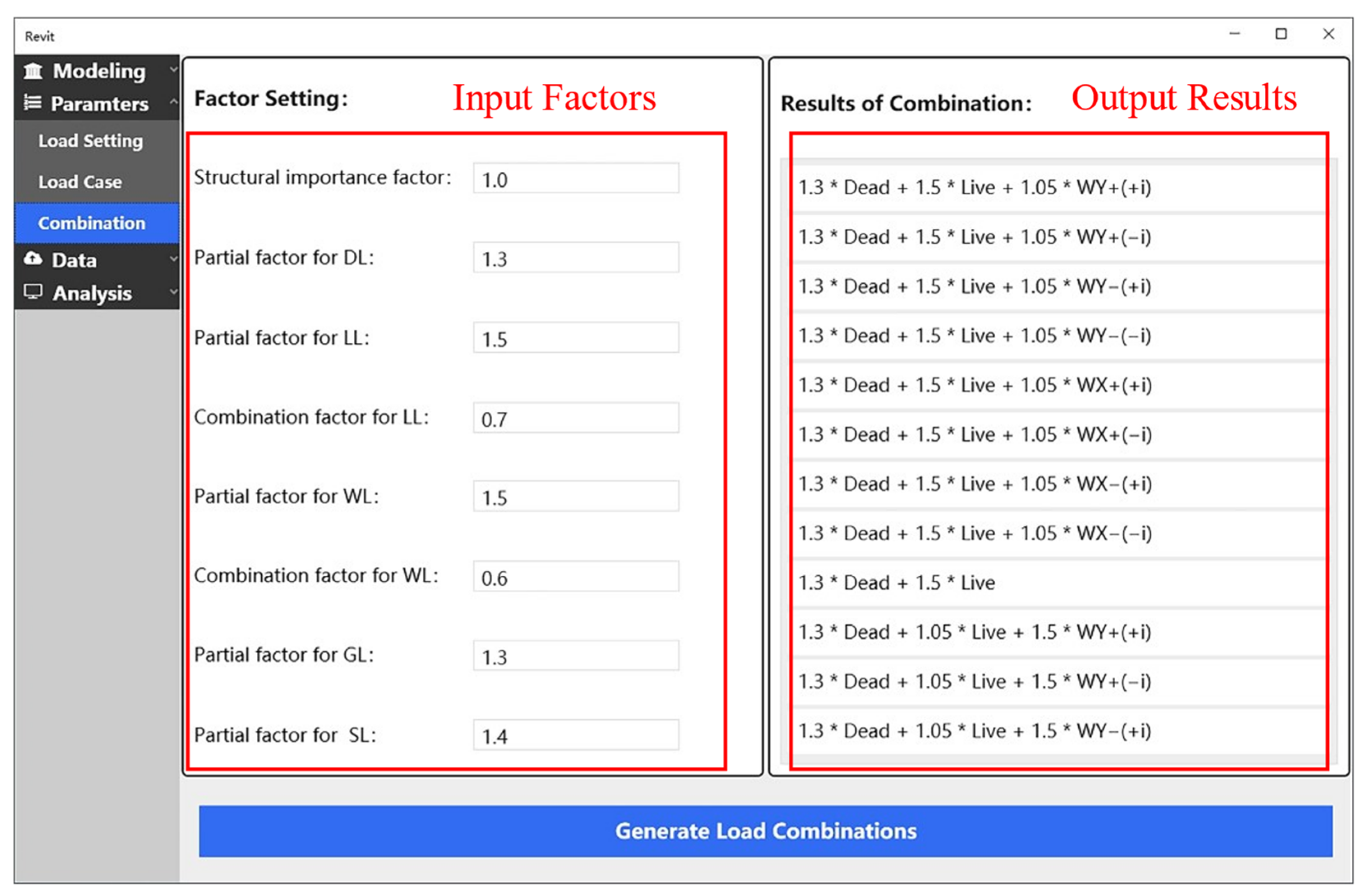
3.2.3. Generation of Load Combination
Load combinations typically include both basic and seismic load combinations. Basic load combinations comprise various mixes of dead, live, and wind loads, while seismic load combinations are designed to specifically consider the effects of seismic response on the structure.
Using the Revit API to generate load combinations requires following these steps:
Instantiate LoadComponent objects, initializing the loadCaseId and factor properties for each individual load case that will be included in the load combination.
Invoke the LoadCombination.Create() method to create a new load combination.
Utilize the SetComponents() method to set loadComponents assign an array of the previously instantiated LoadComponent objects to the newly created load combination.
Since different standards and countries have different load combination factors, the designer must input these load combination factors based on specific design criteria. The user interface that facilitates the input of these factors and the presentation of the corresponding results is illustrated in
Figure 8.
3.3. Data Exchange and Structural Analysis
The main advantages of BIM technology lie in its 3D visualization, parametric modeling, and data integration capabilities. However, it falls short in providing adequate capacity for structural calculation and analysis. Some tools within BIM software offer limited structural calculation functions, but compared to professional finite element software, their analytical capabilities and flexibility are constrained [
12]. This limitation prevents their widespread adoption among designers. The IFC format used for data exchange contains comprehensive information about the model, often resulting in large file sizes. In contrast, finite element software demands only critical parameters for creating a structural model [
14]. Therefore, this paper proposed a method that employs an intermediary database for data exchange between BIM software and finite element software. This approach efficiently transferred model and structural analysis results, addressing the issue of information isolation while also reducing unnecessary information redundancy.
3.3.1. Method of Data Exchange
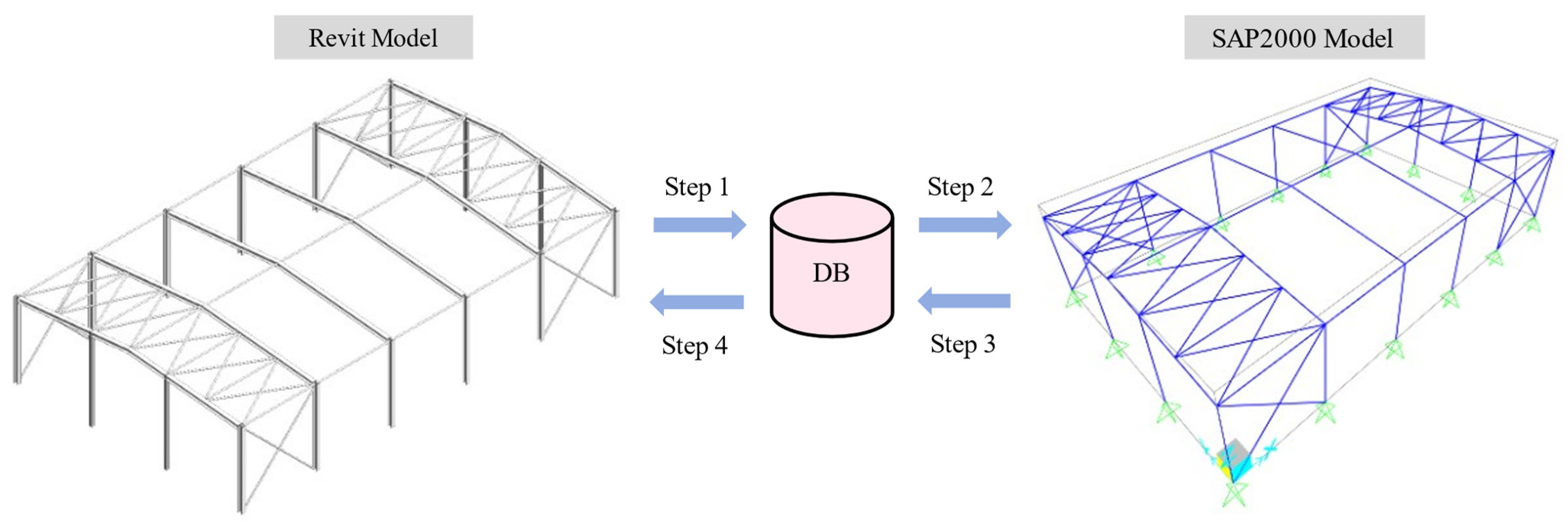
As shown in
Figure 9, this study utilized an SQL Server database to store and manage data in the process of data exchange. The specific steps of data exchange are as follows:
Step 1: Analyze and ascertain the key parameters needed for the SAP2000 model construction and structural analysis, such as the coordinates of each structural member, material properties, and cross-section shapes. Use the Revit API to acquire these parameters and store them into the database.
Step 2: Retrieve the key parameters from the database and utilize the SAP2000 OAPI to construct the SAP2000 model, followed by the automatic initiation of the structural analysis.
Step 3: Store the structural analysis results into the database, including modal periods, member forces, and joint displacements.
Step 4: Extract the structural analysis results from the database and display them through the interface of the developed platform.
3.3.2. Development of Database
The developed platform utilized an SQL Server database for the storage and management of exchange data. SQL Server 2019 is a comprehensive relational database management system (RDBMS) developed by Microsoft, designed to cater to a diverse range of applications. It has been extensively employed in various engineering fields [
31]. In addition, ADO.NET technology facilitates connecting, accessing, and manipulating an SQL Server database [
32]. The storage structure of the database developed in this study is shown in
Table 1.
3.3.3. Structural Analysis Using SAP2000 OAPI
SAP2000 v23 provides open application programming interfaces that enable developers to automate the model construction and analysis of structural model, as well as the extraction of analysis results [
33,
34]. In this study, the SAP2000 OAPI was utilized to construct the corresponding SAP2000 model and perform structural analysis, leveraging data exported from Revit 2018 software and stored in the database.
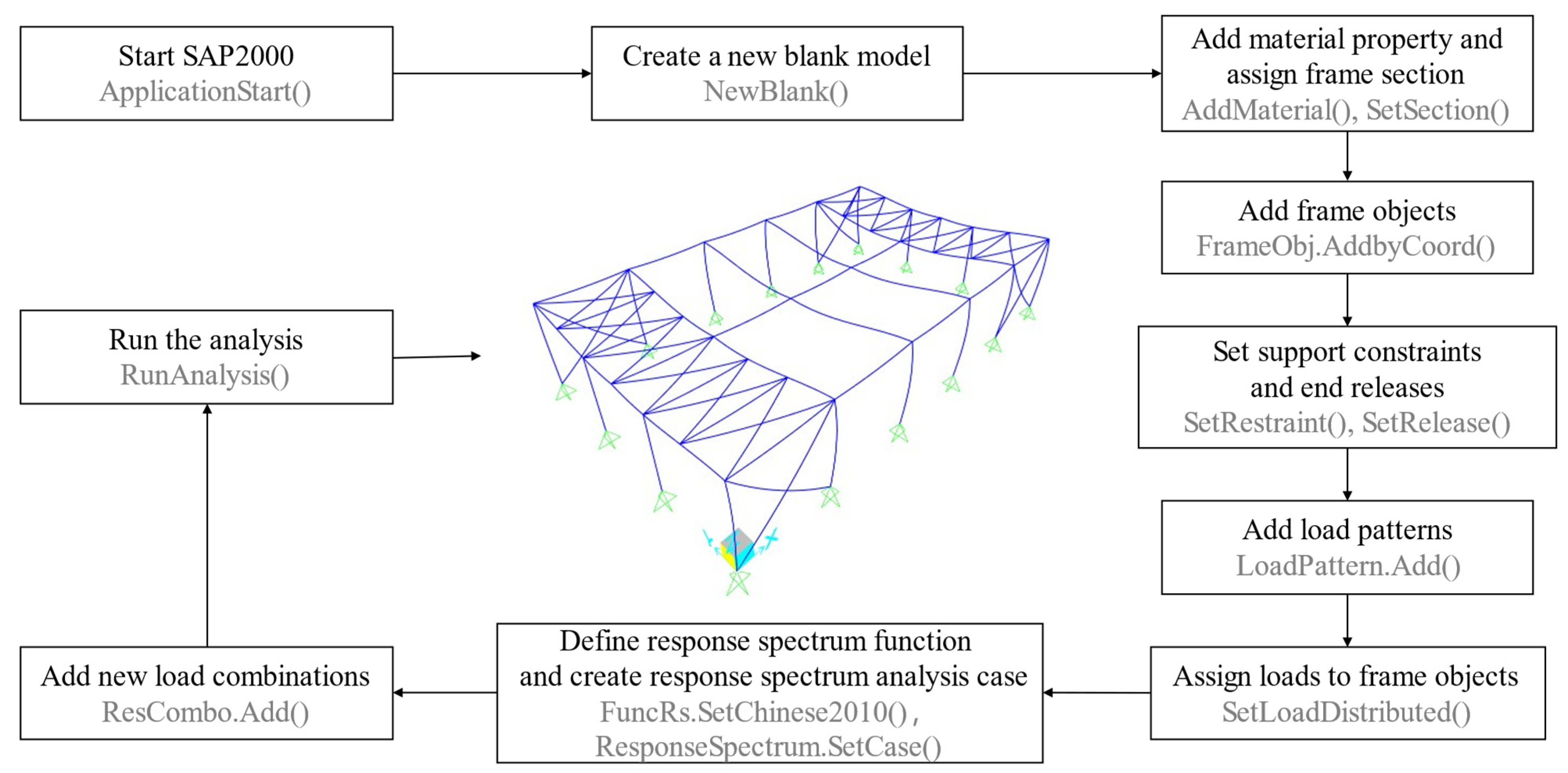
As shown in
Figure 10, the process began with the initialization of the SAP2000 application using the ApplicationStart() method, followed by the creation of a new SAP2000 model with the NewBlank() method. Afterwards, material properties and section attributes were added using the AddMaterial() and SetSection() methods, respectively. The basic construction of the SAP2000 model was then completed by defining the coordinates of each component from the database using the FrameObj.AddByCoord() method, while supports and node constraints required further adjustments. Subsequently, load patterns, load cases, and load combinations were established, and specified loads were applied to the SAP2000 model. For seismic analysis, the response spectrum function was defined using the FuncRs.SetChinese2010() method, where the damping ratio, modal combination method, and other parameters were set. Finally, the RunAnalysis() method was executed to perform the structural analysis, generating the structural analysis results in SAP2000.
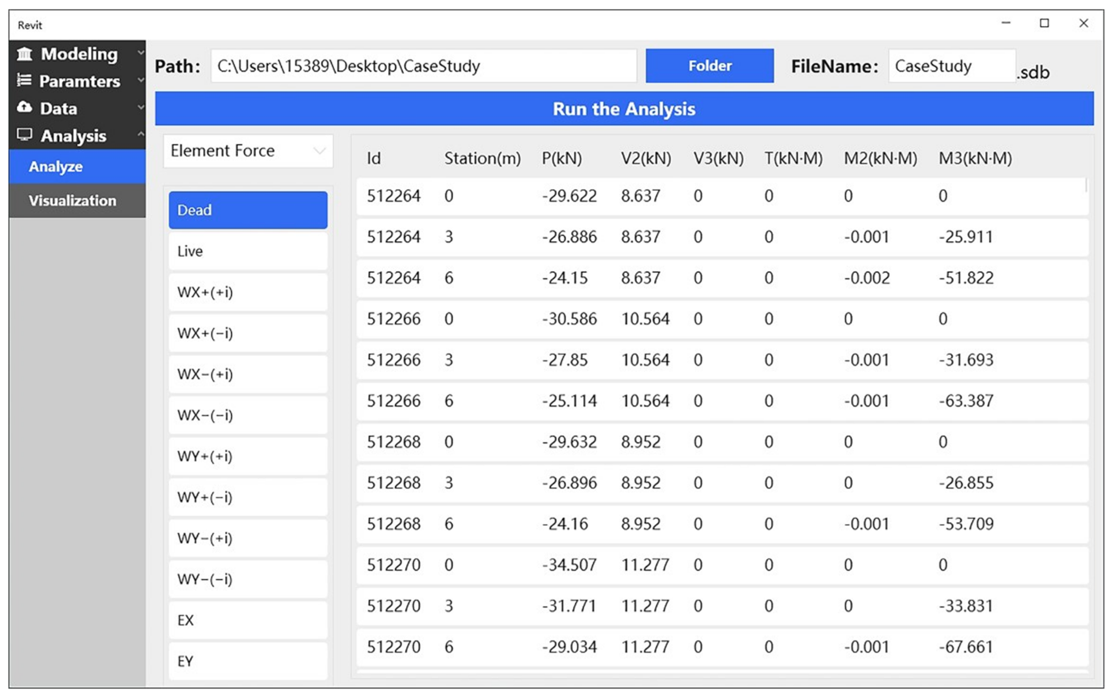
3.3.4. Analysis Results Export
In order to facilitate designers in querying structural analysis results and reusing them, it was essential to extract the analysis outcomes using the SAP2000 OAPI and store them in the database. The Result.ModalPeriod() method can be utilized to acquire the modal periods, frequencies, and other dynamic characteristics. The Result.FrameForce() method can be used to obtain the internal forces of members under specific load cases. Additionally, the Result.JointDispl() method is available to acquire the displacements of joints under specific load cases. In the platform developed in this paper, the designers can query the structural analysis results on the platform interface.
3.4. Visualization of Internal Force in Revit
To streamline the workflow for designers and enhance the visualization of analysis results, this paper introduced a solution that employs Dynamo–Revit API hybrid programming to draw the internal force diagrams under different load cases in Revit software. By integrating this functionality, designers can efficiently access and view the internal force results within Revit software without repeatedly switching between SAP2000, significantly saving time and improving the efficiency of the design process.
3.4.1. Dynamo–Revit API Hybrid Programming
Internal force diagrams of structural members are typically represented by spatial curves, derived by interpolating a series of control points. Solely depending on Revit API to generate these spatial curves can be a complex and labor-intensive endeavor. To streamline this task, this study employed Dynamo–Revit API hybrid programming, which leverages the capabilities of both Dynamo and the Revit API.
Dynamo is a parametric design platform that operates within the Revit environment, supporting visual programming and featuring a powerful library of geometric nodes [
35,
36]. The geometric node library in Dynamo, with its diverse array of graphical logic functions, effectively compensates for the shortcomings of Revit software in constructing complex spatial geometries.
In this paper, spatial curves that make up internal force diagrams were generated by invoking functions from Dynamo’s geometric node library. The process used a hybrid programming approach and avoided direct manipulation of the Dynamo interface. The first step was to include the necessary dynamic link libraries in the development environment, specifically DynamoRevitDS.dll, DynamoServices.dll, LibG.Interface.dll, ProtoGeometry.dll, and RevitNodes.dll. Subsequently, functions from the Dynamo geometric node library were employed to process control point data and generate the required spatial curves. After generating the spatial curves, due to the differences in the representation of geometric objects between the Revit API and Dynamo, the ToRevitType() method was utilized to convert Dynamo geometric objects into types recognizable by the Revit API.
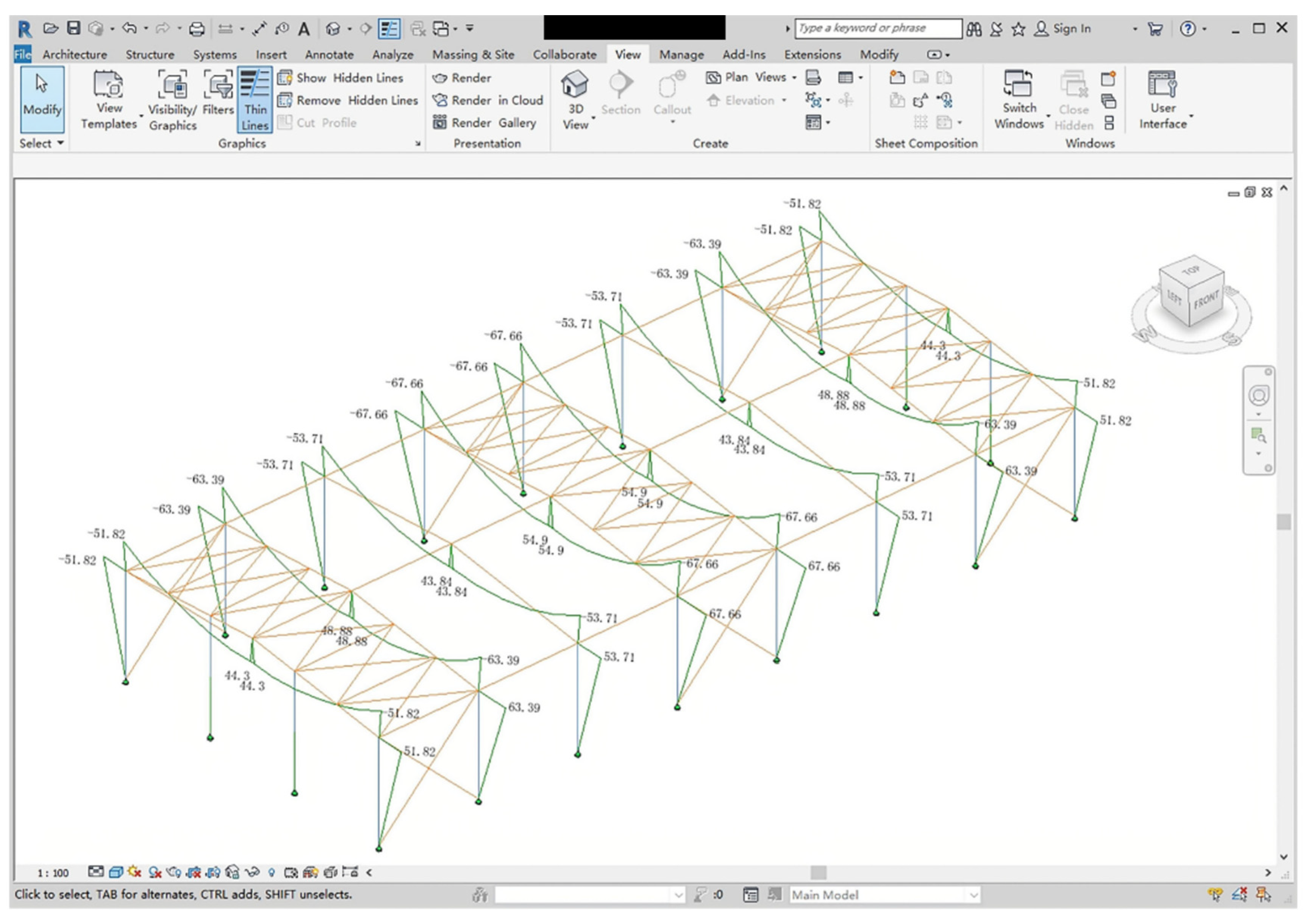
3.4.2. Drawing Internal Force Diagrams for Structural Components in Revit
To create internal force diagrams in Revit 2018, the process began by querying the internal force values for each structural member, such as axial force, shear force, and bending moment. These values could be obtained from the database. Then, the offsets for the control points were calculated based on the internal force values and the geometric properties of the member, ensuring that the offsets were proportional to the forces to represent the internal force distribution accurately. Next, smooth curves that represented the internal forces were generated using the NurbsCurve.ByPoints() method. Subsequently, these curves were converted into curve objects in Revit API by using the ToRevitType() method. Finally, these curve objects were passed as parameters to the Create.NewModelCurve() method to draw the internal force diagrams in the Revit environment. To indicate the magnitude of the internal forces, numerical or textual annotations were added to the diagram, ensuring readability. This approach minimizes the need for designers to repeatedly use SAP2000, thereby reducing dependency on finite element analysis software and enhancing overall design efficiency.
5. Conclusions
In this study, a BIM platform for the design of single-story steel structure factories was developed using Revit API, SAP2000 OAPI, and other technologies. The platform integrated the BIM modeling function of Revit software and the structural calculation function of SAP2000 software, which provided a new solution for the design of single-story steel structure factories. The specific conclusions are as follows:
The platform developed in this paper facilitates the automatic generation of BIM models, the application of loads, structural analysis, and the visualization of internal forces for single-story steel structure factories. A case study was successfully conducted using this platform, effectively demonstrating the entire process from BIM modeling to structural analysis. Furthermore, due to the geometric and design similarities, it is also applicable to other steel structures such as warehouses and buildings, thus contributing to the existing body of knowledge.
The platform developed in this paper significantly enhances the efficiency of designing single-story steel structure factories. Compared to traditional methods, the time required for BIM modeling and structural analysis is substantially reduced. Additionally, the platform notably decreases the learning cost of software for designers and simplifies operational complexity.
The accuracy of the analysis results obtained through the platform developed in this paper has been thoroughly validated. When compared with results from other calculation software, the maximum deviation is within 0.6%, which satisfies the precision needs of designers.
Although the platform developed in this paper dramatically optimizes the design process of single-story steel structure factories, there are still some limitations. The platform currently includes exclusive integration with SAP2000 for automatic structural analysis and calculation, with no interface for other finite element software. In the future, efforts will be focused on expanding the platform’s compatibility to include interfaces for other finite element analysis software.


