Article

Experimental Study on Seismic Performance of Prefabricated Monolithic Concrete–Polystyrene Panel Composite Wall Panels

1
School of Civil Engineering, Shandong Jianzhu University, Jinan 250101, China
2
Key Laboratory of Building Structural Retrofitting and Underground Space Engineering, Shandong Jianzhu University, Ministry of Education, Jinan 250101, China
3
Engineering Research Institute of Appraisal and Strengthening of Shandong Jianzhu University Co., Ltd., Jinan 250101, China
*
Authors to whom correspondence should be addressed.
Buildings 2024, 14(2), 442; https://doi.org/10.3390/buildings14020442
Submission received: 13 December 2023 / Revised: 23 January 2024 / Accepted: 2 February 2024 / Published: 6 February 2024
(This article belongs to the Special Issue Advances in Novel Precast Concrete Structures)

Abstract

:
A normal composite wall panel is a structural component composed of polystyrene insulation boards and concrete surface layers reinforced with steel wire mesh. It can be entirely prefabricated in a factory or constructed with the concrete surface layers cast on-site. A novel prefabricated monolithic concrete–polystyrene panel composite wall panel (CPC wall panel) is proposed in this study. The CPC panel features a middle part that is prefabricated in the factory while the reinforced concrete regions at its two side ends are cast on-site. To evaluate the seismic performance of the wall panel, 18 CPC specimens were designed, manufactured, and quasi-statically tested, through which the structural behaviors, failure mode, and load-bearing capacity were studied. In addition, the influences of the height-to-width ratio and the vertical compressive stress level on the seismic performance of the CPC panels were also investigated. The test results showed that the connectors spaced at 400 mm × 500 mm could ensure the concrete layers on both sides of the polystyrene board worked collectively under seismic conditions. When subjected to lateral loads, the interface between the newly poured concrete and the existing concrete exhibited good bonding. Moreover, the failure mode of the CPC wall panel was largely correlated to the height-to-width ratio that, for specimens having four steel bars of 12 mm diameter and a height-to-width ratio greater than 1, the flexural failure was initially developed, followed by diagonal shear failure. In specimens with a height-to-width ratio of 1, flexural and diagonal shear failures occurred almost simultaneously. For specimens with a height-to-width ratio of less than 1, the final diagonal shear failure was predominant. The longitudinal reinforcing bars at the two ends of the CPC panels could effectively improve their lateral load-bearing capacity, with the enhancement influenced by the height-to-width ratio, the vertical load applied to the wall panel, and the cross-sectional area of the steel bars. In practice, the lateral load-bearing capacity of the CPC panel can be conservatively evaluated using the calculation method of the reinforced concrete shear walls. Finally, the ductility of the CPC specimens was affected by the height-to-width ratio and the axial compressive stress level, such that the specimens with a larger height-to-width ratio and lower axial compressive stress exhibited better ductility.

1. Introduction

A composite wall panel is a component that allows the insertion of thermal insulation materials into the interior of a wall. The middle of the wall panel is composed of a thermal insulation material (such as polystyrene board), and the two sides of the polystyrene board are made of a steel mesh concrete surface layer or a mortar surface layer. Through the reasonable setting of connectors, the steel wire mesh concrete surface layers on both sides of the thermal insulation material can be connected as a whole to bear the entire force. This kind of wall panel not only improves the thermal insulation performance of the wall, but prevents the thermal insulation material in the external wall from falling off. Composite wall panels are divided into non-load-bearing wall panels for external maintenance structures only, and load-bearing wall panels used as vertical load-bearing components. There are more types of non-load bearing wall panels, such as Autoclaved Lightweight Aerated Concrete (ALC) wall panels in [1], Glass Fiber-Reinforced Cement (GRC) panels in [2], lightweight wall panels with a combination of foam concrete and cement fiber board developed by Fernando et al. [3], and lightweight sandwich wall panels consisting of Lightweight Foam Concrete (LFC) panels and Mineral Hydrated Foam Material (MHFM) insulation developed by Dong-Hyeon Shin et al. in [4]. Domestic and foreign scholars have carried out some research on the use of a composite wallboard as a vertical load-bearing component. In reference [5], a composite wallboard in which one side was a concrete load-bearing structure and the other side was a layer protecting the insulation board was studied. Under the action of a horizontal wind load, the protective layer, the insulation board, and the structure remained sound and did not fall off. Amran et al. [6] carried out a study on the vertical load-bearing capacity of sandwich composite wall panels faced with foam concrete, wherein both sides of the face contained a reinforcement mesh comprising 6 mm diameter steel trusses for tying. The study determined that the connection ensured the face sides of the wall panels were jointly loaded, and it was found that the wall panels’ load-bearing capacity was related to the height-to-width ratio. Pavese et al. [7] conducted seismic performance tests on a structural model of a two-story house with concrete sandwich composite wall panels, with field-sprayed concrete containing a galvanized steel wire mesh on both sides of the insulated panels, and tensile reinforcing bars with a diameter of 8 mm and a spacing of 300 mm between the upper and lower wall panels. The tests showed that openings in the wall panels reduced their bearing capacity, and the structure showed good integrality.
References [8,9,10,11,12,13] studied various types of wall panels with different connectors, such as GFRP restraint connectors and grid-type shear connectors, and obtained the mechanical properties of the wall panels with various types of connectors. In addition, there have also been some studies on composite sandwich panels with different fibers added to concrete panels. In reference [14], the seismic performance of a thermal insulation composite wall panel with steel mesh ceramsite concrete containing alkali-resistant glass fiber was studied. The wall panel was cast-in-place, and the vertical reinforcement of the steel mesh was used for reliable anchoring. The results showed that the alkali-resistant fiber improved the crack resistance of the wall panel, and the wall panel showed good ductility. The study in [15] conducted seismic performance tests on a structural model of a two-story building constructed with ultra-high-performance concrete sandwich composite wall panels on the face, and the upper and lower wall panels were reliably connected using pre-embedded bolts. The tests showed that the structure achieved good seismic performance, but the connecting structure was complicated. References [16,17,18] studied a new type of precast concrete sandwich wall panel composed of two basalt fiber-reinforced polymer (FRP)-reinforced geopolymer concrete wythes and an insulation layer. The results showed that the larger the slenderness ratio was, the lower the axial bearing capacity of the wall panel was. Additionally, as the ratio of load eccentricity-to-sectional thickness increased, the axial load capacity decreased.
References [19,20,21] studied a load-bearing composite wall panel with a thickness of 120 mm and a concrete surface layer of 25 mm; the wall panels were all prefabricated, and it was found that when a vertical load was applied, the thinner surface layer was damaged as a result of local instability, and the concrete surface layer could not fully play its role. For example, the steel mesh in the surface layer was either discontinuous or the upper and lower ends were not reliably anchored, and no other structural measures were taken. Under lateral loading, when the height-to-width ratio of the wall panel was small, the horizontal cracks running along the discontinuous section of the steel mesh were opened, and the steel mesh could not fully play its role, as a result of which the bearing capacity of the component was low. In summary, the research on load-bearing composite wall panels can be divided into two types: one is the research on cast-in-place composite wall panels, whereby the surface concrete on both sides of the wall insulation panel is cast-in-place on-site, and it is reliably anchored via the vertical reinforcement of the surface steel mesh, or the structural steel reinforcement is set up to ensure that the wall panels are fixed at the upper and lower ends and can thus transfer the horizontal force. In the other case, the wall panels are all prefabricated in the factory and assembled on site, and the connections between the wall panels, as well as the fixings of the upper and lower ends, require special connectors. If the composite wall panel is cast-in-place, the construction process will be more costly and the cycle will be longer. If all the panels are prefabricated, the structure becomes complicated, limiting the transfer of the lateral load and resulting in poor seismic performance.
To overcome the limitations associated with fully prefabricated or fully cast-in-place composite wall panels, we have developed a new solution—the prefabricated monolithic composite wall panel. The thickness of the wall panels is 200 mm, the middle is composed of 100 mm thick polystyrene panels, and the two sides are composed of 50 mm thick steel wire mesh coated in concrete. A special new type of connector is used to connect the two sides of the steel wire mesh into a whole, and this can be fixed accurately to the position of the steel reinforcement mesh. Each wall panel’s middle section is prefabricated in the factory and installed on-site. The steel wire mesh of the wall panel is discontinuous on the upper and lower layers without anchoring. The wall panels are mounted with a backing belt at the end and cast-in-place at the construction site, while the vertical reinforcement bars are set up on a post-pouring belt running through the upper and lower layers, and strong longitudinal reinforcement bars at the bottom of the structure are anchored into the foundation, forming a monolithic concrete–polystyrene composite load-bearing wall panel. No other connecting structures are inserted between and upon the upper and lower ends of the wall panels. In this paper, we designed and fabricated 18 specimens of prefabricated monolithic concrete–polystyrene panel composite wall panels. The seismic performance of the prefabricated monolithic composite wall panels under horizontal earthquake actions was investigated through quasi-static testing. The effects of the height-to-width ratio and vertical load on the seismic performance of the wall panels were analyzed, and the reliability of the connector arrangement was validated. The general flow chart for this is shown in Figure 1.

2. Test Overview

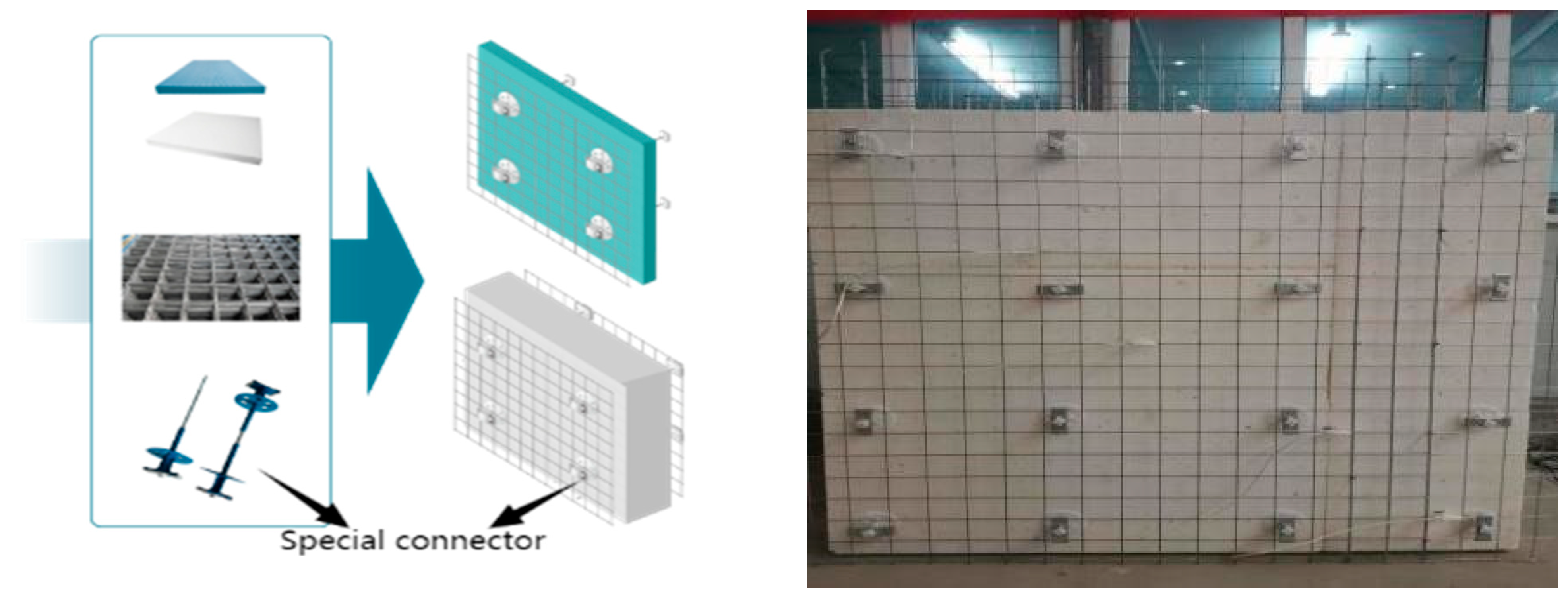
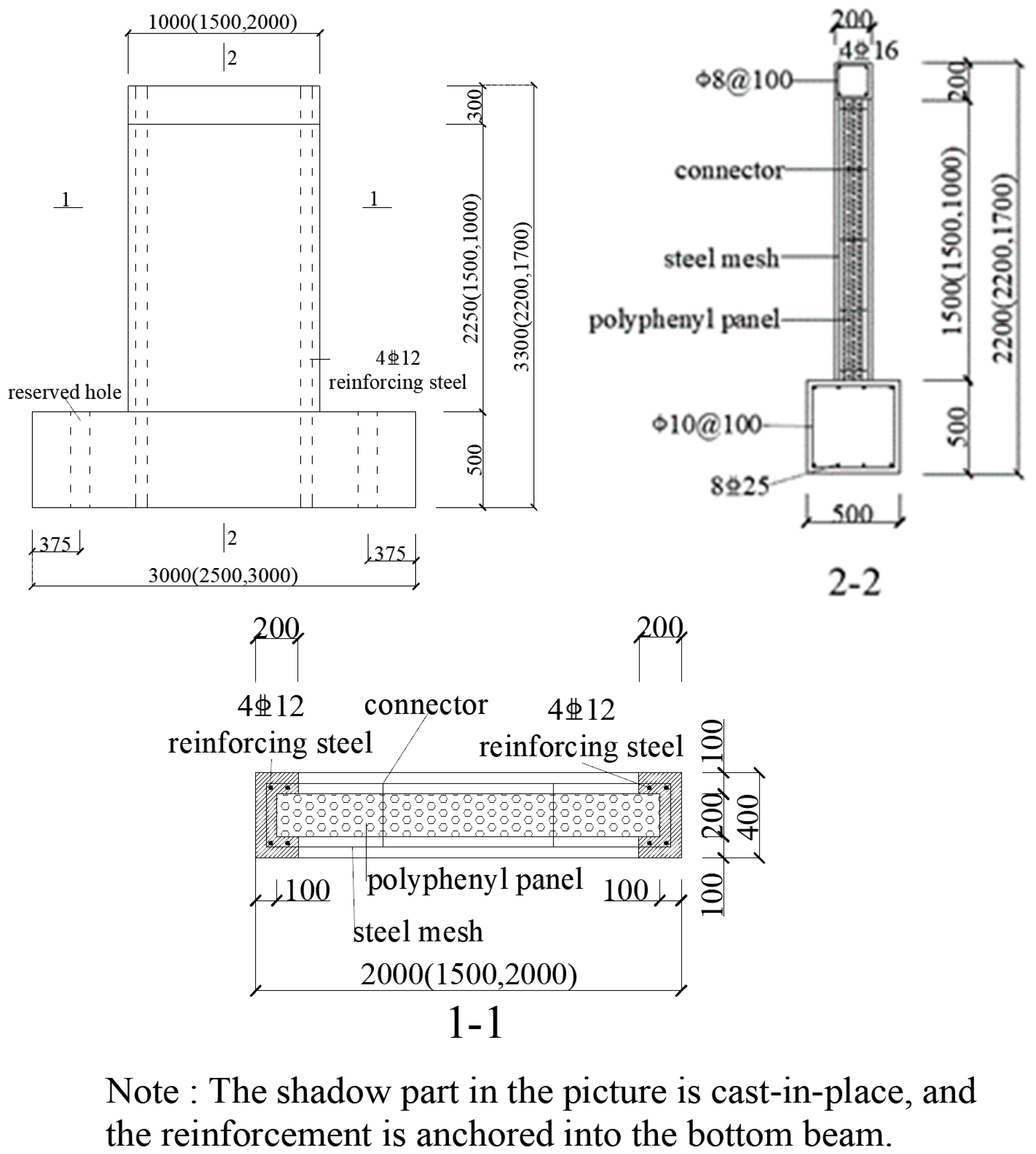
2.1. Composition of Concrete–Polystyrene Composite Wall Panels
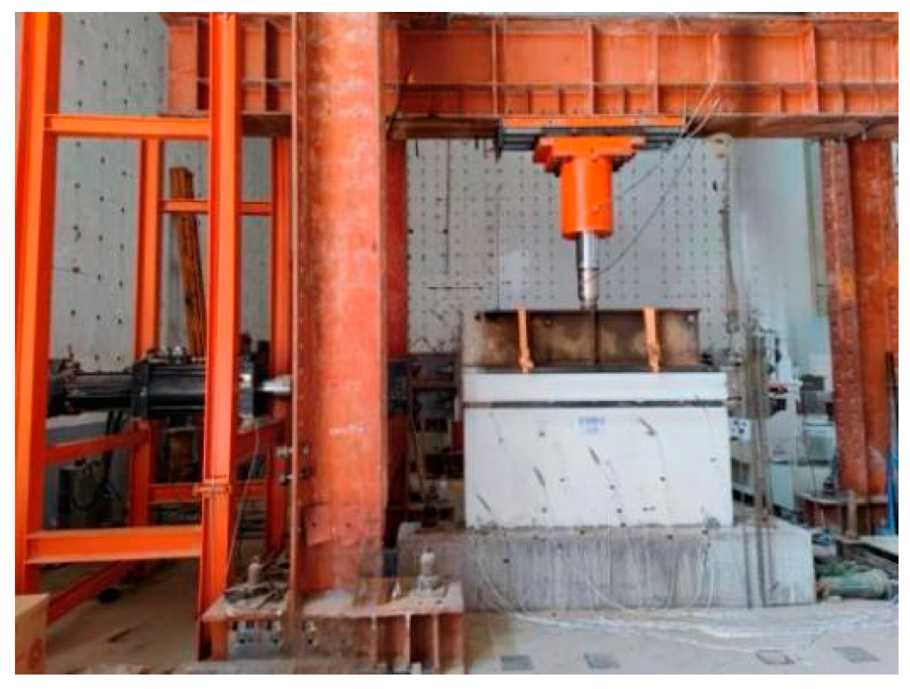
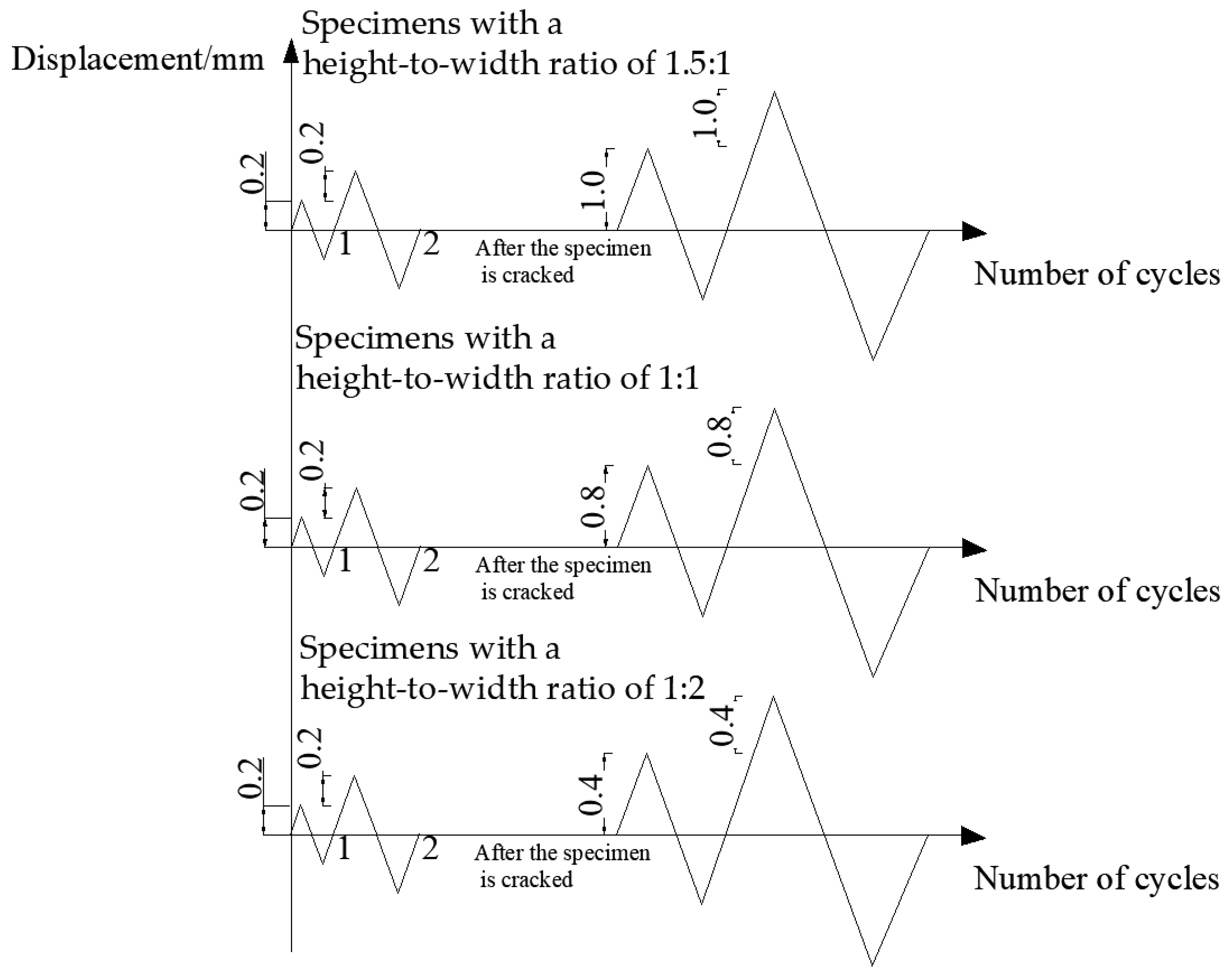
The CPC panel used in this study consists of a polystyrene board, steel wire mesh, and concrete facing applied on both sides, as shown in Figure 2. The wall panel has a thickness of 200 mm, with a 100 mm thick polystyrene board in the middle and a 50 mm thick concrete surface layer containing steel wire mesh on both sides. The two layers of steel wire mesh were fixed using special connectors, which not only conveniently connects the polystyrene boards with the steel mesh, but also accurately fixes the position of the steel mesh. This ensures that the concrete surface layer and the internal insulation sandwich layer can work effectively as a cohesive unit. The diameter of the steel mesh reinforcement is 3 mm, and the mesh size is 75 mm. The wall panel is prefabricated in specific factories and cast-in-place at both ends. Vertical reinforcement bars are incorporated through the upper and lower layers of the cast-in-place parts, forming an integrated composite wall panel structure.
Three different height-to-width ratios were tested in designing the specimens, with specific dimensions of 1500 × 1000 mm, 1500 × 1500 mm, and 1000 × 2000 mm, respectively. Vertical compressive stresses of 1.20 MPa, 0.80 MPa, and 0.40 MPa were applied to investigate the effects of vertical pressure on the seismic performance of the wall panels. A total of nine groups of 18 specimens was tested. The numbers and requirements of the specimens are shown in Table 1.
The specimens comprised a top beam and a floor beam to facilitate the application of vertical and lateral loads, with the anchoring of the specimens to the test stand. The top beam had a cross-section of 200 × 200 mm with 4C16 longitudinal reinforcement and A8@100 hoop reinforcement. The floor beam had a cross-section of 500 × 500 mm, with 8C25 longitudinal bars and A10@100 stirrups. The middle of the specimens was prefabricated, and the two ends comprised 200 mm of cast-in-place concrete. Each end of the specimens was equipped with 4C12 vertical reinforcement, with the reinforcement anchored in the top and bottom beams. The connectors were spaced vertically at 400 mm and horizontally at 500 mm.
The specific section size and reinforcement of the specimen are shown in Figure 3.
The concrete strength grade of the composite wall panel, top beam, and ground beam was C30, and the measured cube compressive strength of the composite wall panel concrete was 30.9 MPa. The yield strength of the C12 vertical reinforcement was measured to be 428 MPa, and the ultimate strength was 563 MPa. The ultimate strength of the steel wire mesh reinforcement was 650 MPa, and the conditional yield strength was 553 MPa (0.85 times the ultimate strength).

2.2. Loading Test

A vertical load was applied using a hydraulic pressure stabilizing loading system. During the test, a vertical load was first applied up to the required load value, which was kept constant during the application of the lateral load. An MTS electro-hydraulic servo loading system was used to apply the reciprocating lateral load, and the test loading device is shown in Figure 4.
This study employed a displacement-controlled low-cycle reversed loading method, which involved the repetitive loading and unloading of the specimens in both positive and negative directions. The three sizes of specimens were loaded with a rate of increase of 0.2 mm until cracking occurred. After cracking, the specimen with a height-to-width ratio of 1.5:1 was loaded with a displacement increment of 1.0 mm, the specimen with a height-to-width ratio of 1:1 was loaded with a displacement increment of 0.8 mm, and the specimen with a height-to-width ratio of 1:2 was loaded with a displacement increment of 0.4 mm. Each displacement level was cycled once, as depicted in Figure 5. The test was stopped when the specimen’s horizontal bearing capacity had reduced to 85% of its ultimate load-bearing capacity after cycling.

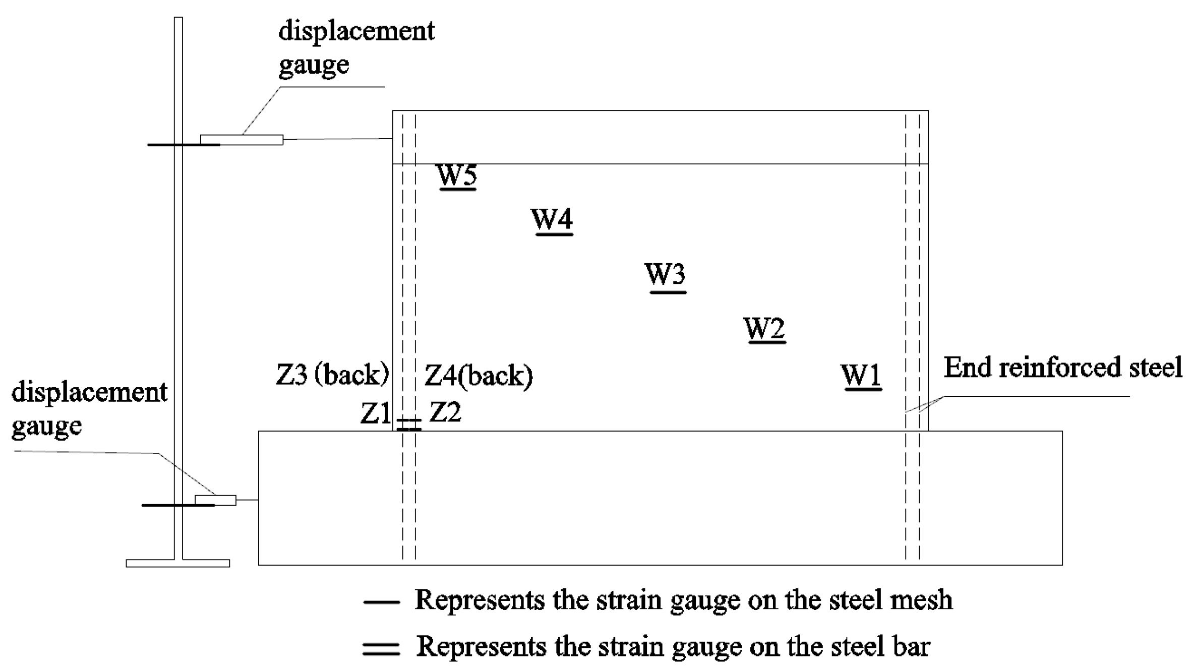
2.3. Layout of Measurement Points and Data Collection

The lateral load magnitude was automatically measured using the MTS loading system. External displacement gauges were placed in the centers of the top and bottom beams of the specimens, and data were collected using a high-performance data collector (TDS-540) to determine the real displacement of the specimen under lateral loading. Steel reinforcement strain gauges were arranged on the horizontal steel wire mesh and the reinforcing steel bar; the former were placed at five measurement points spaced evenly in the diagonal direction across the specimen, and the strain gauges on the reinforcing steel were placed at the bottom of the specimen. The arrangements of the displacement and reinforcement strain measurement points are shown in Figure 6.

3. Test Results and Analyses

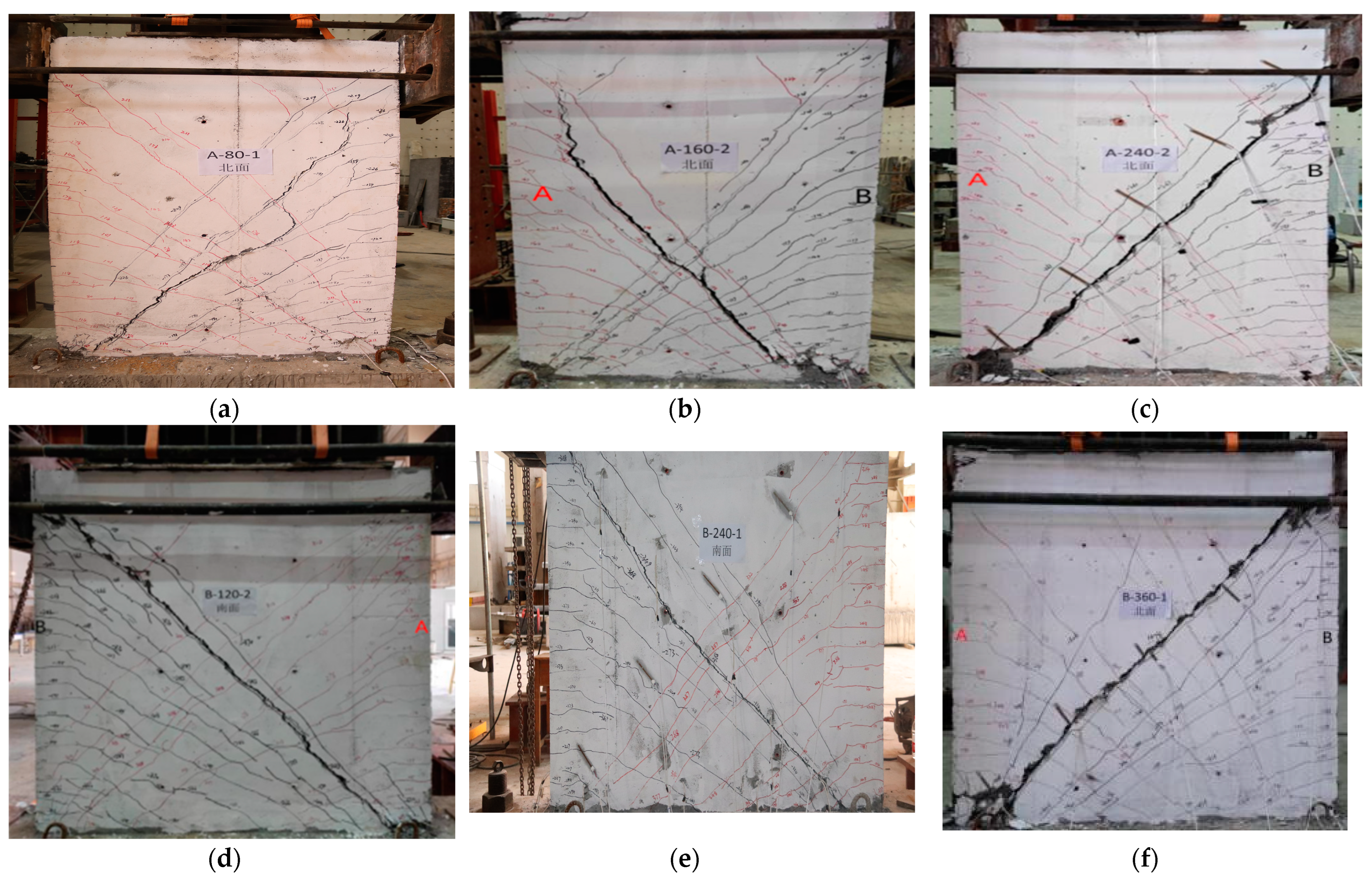
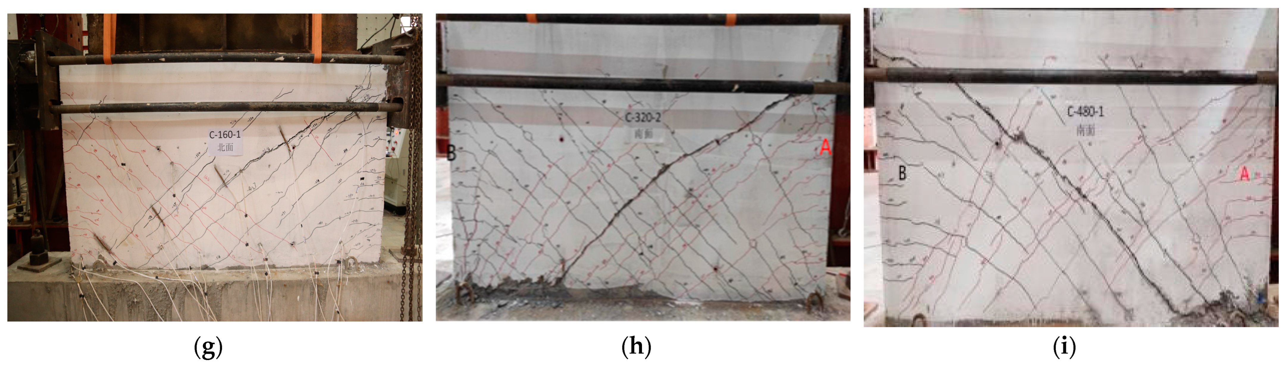
3.1. Failure Mode of Specimens

The modes of initial crack development in each specimen throughout the entire loading process were generally similar, with horizontal cracks emerging first under lateral loading. As the load increased, new horizontal cracks formed and gradually developed into oblique cracks. The reason for this was that the main tensile stress was generated in the specimen under both vertical and lateral loads. The main tensile stress at the ends was vertical, while the middle main tensile stress was at an angle with the cross-section of the specimen. When the main tensile stress exceeds the tensile strength of the concrete, cracks occur. Therefore, horizontal cracks were generated at the ends of the specimen, while oblique cracks developed in the middle. By observing the entire test phenomenon, it can be seen that specimens with different height-to-width ratios exhibited different failure modes. In the specimen with a height-to-width ratio of 1.5:1, the longitudinal reinforcements reached their yield point first, and noticeable horizontal cracks were observed at the bottom of the specimen. Subsequently, the concrete in the compression zone was crushed, marking the specimen’s maximum bearing capacity. With the application of further load, a prominent main oblique crack formed diagonally along the specimen, significantly reducing its bearing capacity. Consequently, the specimen exhibited flexural failure initially, followed by diagonal shear failure.
When the specimen with a height-to-width ratio of 1:1 approached its ultimate load-bearing capacity, the longitudinal reinforcements in the ends reached their yield strength, leading to the emergence of vertical cracks in the compression zone and signs of concrete crushing. Finally, the main oblique cracks that emerged in the diagonal direction along the specimen caused shear failure in the oblique section. Although the final damage mode was oblique cross-section shear failure, observations from the test indicated the longitudinal reinforcement in the specimen reached its maximum bearing capacity and also yielded, and the compression zone of the concrete showed signs of crushing. These observations suggest that flexural failure had occurred or was on the verge of occurring. Specimens with a height-to-width ratio of 1:2 eventually suffered shear failure due to the development of oblique cracks. When the specimens reached their ultimate horizontal bearing capacity, some of the end reinforcing bars yielded, but the concrete in the compression zone was not crushed. The final failure mode was diagonal shear failure, and no flexural failure occurred. After shear failure, further loading resulted in increased displacement, but the horizontal bearing capacity significantly decreased; no new cracks were generated. The original cracks gradually became wider or more extended, and the concrete in the corner of the wall panel became crushed and dislodged, exposing the steel mesh and longitudinal reinforcement.
The specimens exhibited two types of failure modes, namely, flexural failure and diagonal shear failure. The analysis of the reasons behind the different failure modes was as follows: For specimens with a height-to-width ratio of 1.5:1, under the applied vertical load condition, the shear resistance under lateral load exceeded the bending capacity of the normal section, resulting in the occurrence of flexural failure first. For specimens with a height-to-width ratio of 1:1, the shear resistance was approximately equal to the bending capacity of the normal section. Consequently, flexural failure and oblique section failure occurred almost simultaneously. In the case of specimens with a height-to-width ratio of 1:2, the bending capacity of the normal section significantly exceeded the shear bearing capacity. As a result, oblique section failure occurred while flexural failure did not occur.
Under the action of quasi-static cyclic loading, the concrete surface layers on both sides of the polystyrene board remained whole throughout the testing process. The prefabricated and cast-in-place concrete were well combined without separation, indicating that the concrete surface layer and the polystyrene board became a single unit via the fixation effect of the steel mesh and the pull bolt connector. The pull bolt connector balanced the vertical and lateral loads of the surface layers on the left and right sides, ensuring an overall force equilibrium and the cohesive behavior of the wall panel during seismic events.
The typical failure mode of the specimens is shown in Figure 7.

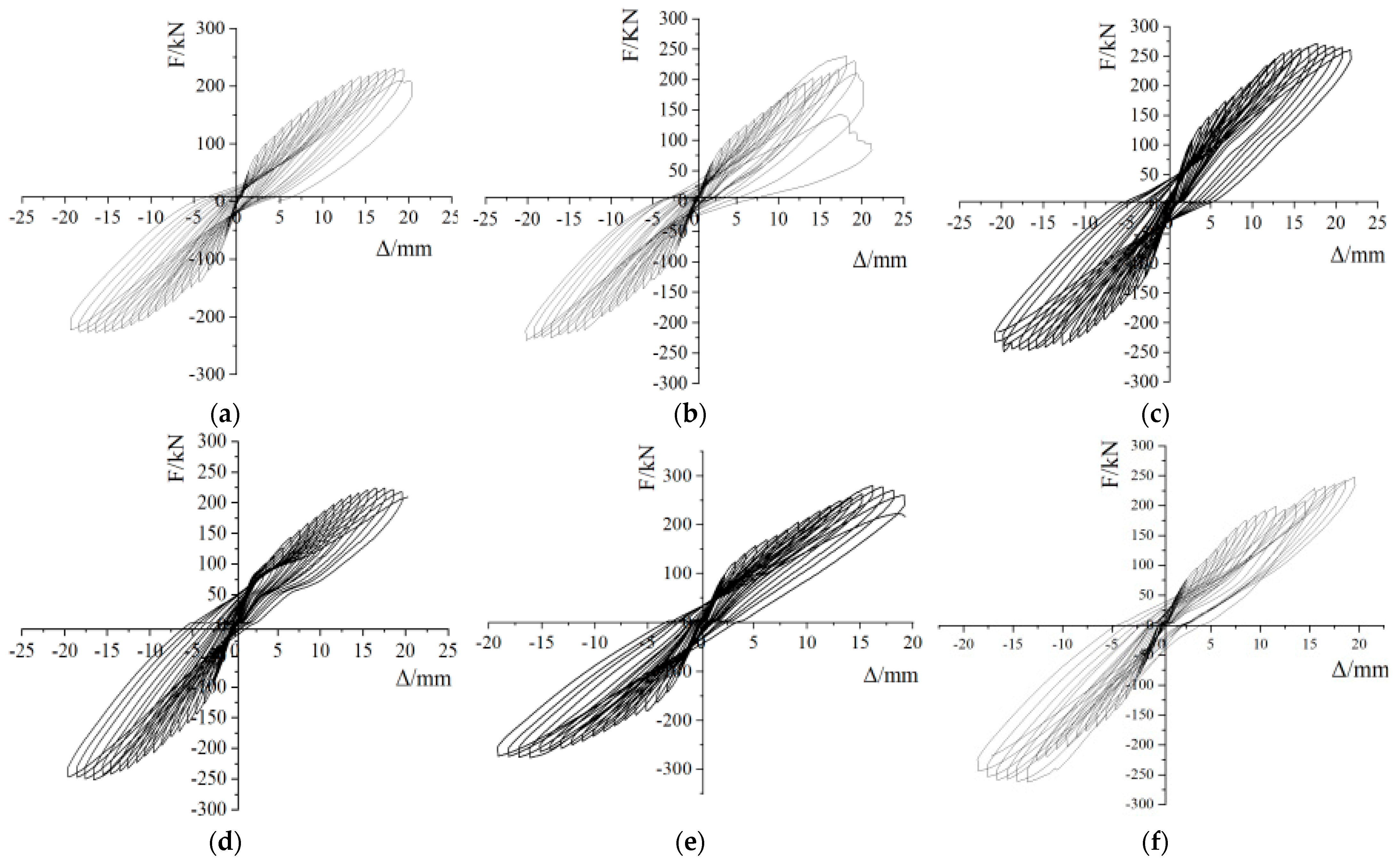
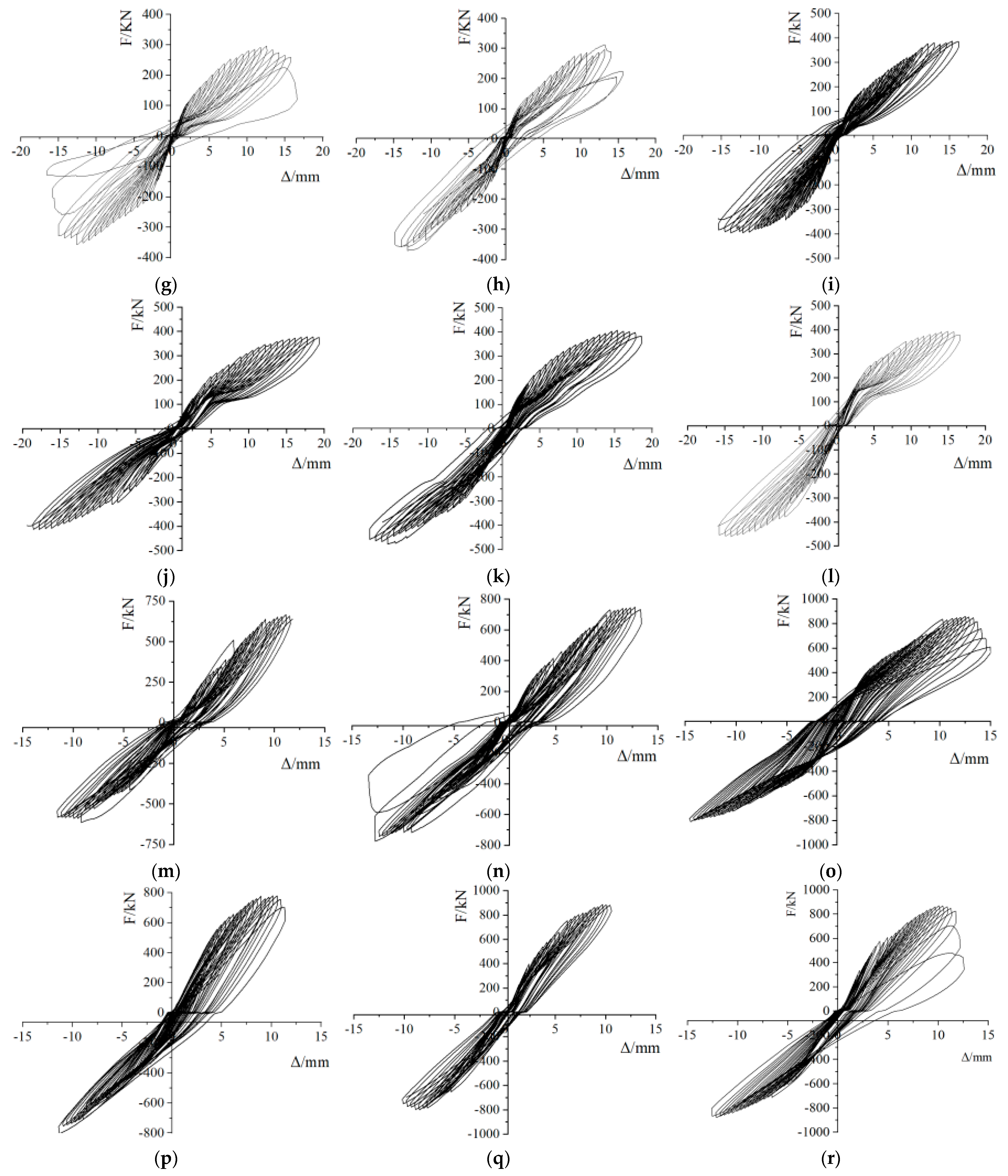
3.2. Hysteresis Curve and Energy Consumption

The hysteresis curves for each specimen are shown in Figure 8.
The hysteresis curves of the specimens generally adopted an inverted S shape, and there was a large shear slip. After reaching the ultimate load-bearing capacity, the stiffness and bearing capacity suddenly dropped. The reason was that the specimens all eventually underwent shear failure. Specimens with small height-to-width ratios and large axial pressure showed poor energy dissipation performances.

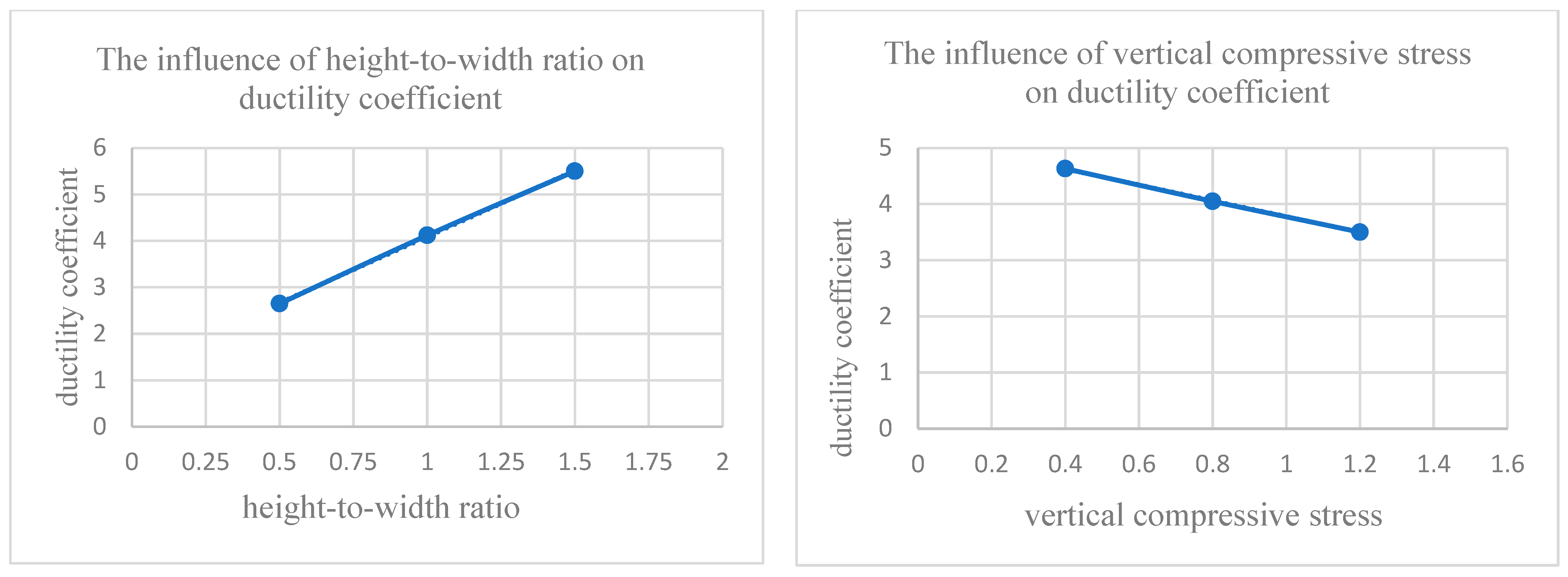
3.3. Ductility Analysis of Specimen

Ductility refers to the ability of materials, components, or structures to deform without significant reductions in post-yield bearing capacity under loading or other indirect effects. In this paper, the displacement ductility coefficient was used to analyze the ductility of our composite panel, which is calculated according to Formula (1):
μ = u / y
where u is the ultimate displacement and y is the yield displacement.
The test results regarding the ductility coefficient of each specimen are shown in Table 2.
The ductility coefficient of specimens with the same height-to-width ratio was averaged to establish the relationship between the specimen ductility and the height-to-width ratio. Similarly, the ductility coefficient of specimens with the same vertical compressive stress was averaged to determine the relationship between the specimen ductility and the vertical compressive stress. This relationship is illustrated in Figure 9.
It could be seen from Table 2 and Figure 9 that the greater the height-to-width ratio of the specimen, the better its ductility, and the greater the vertical pressure, the worse the ductility. The tests showed that specimens with a large height-to-width ratio experienced flexural failure, while those with a small height-to-width ratio exhibited diagonal shear failure. When the normal section was destroyed, the reinforcing steel bar yielded first, inducing a large deformation. The deformation ability of the component was strong, indicating good ductility. The deformation capacity of shear failure is related to the performance of the horizontal steel wire mesh. As the mesh was composed of cold-drawn low-carbon steel wire, its ductility was poor, meaning specimens with small height-to-width ratios have poor ductility.

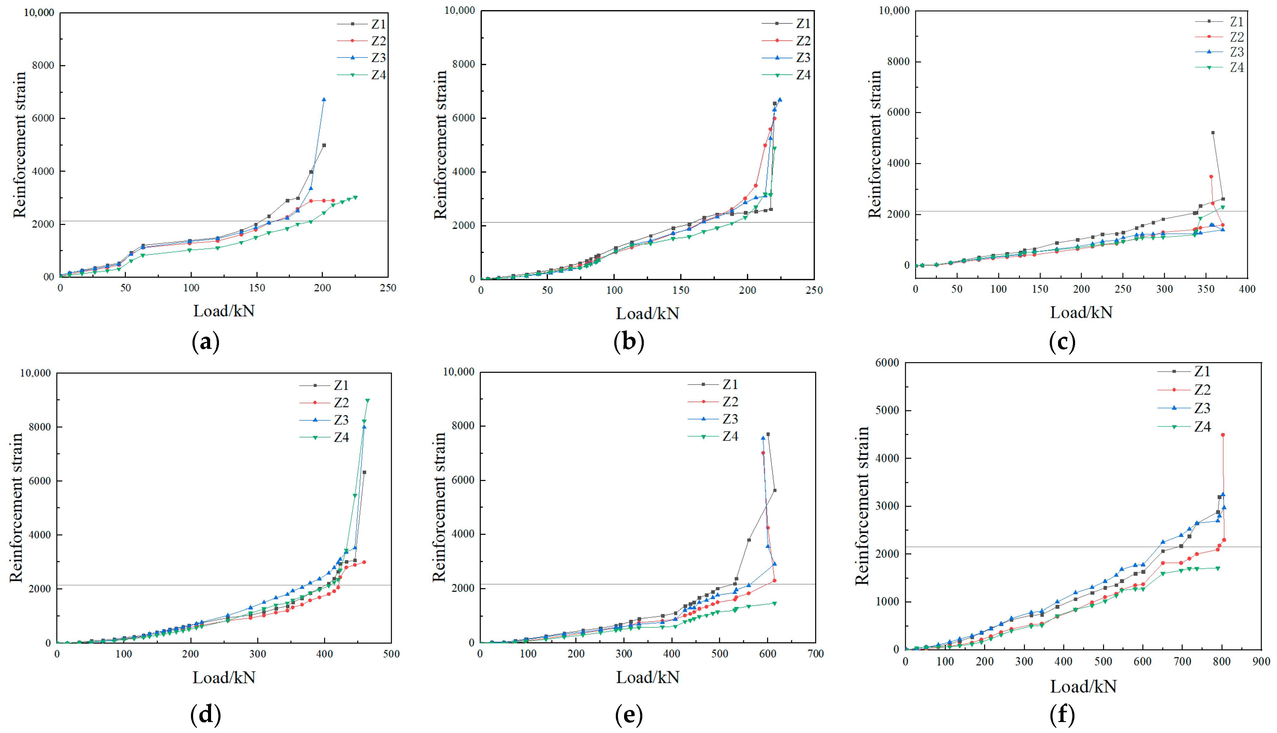
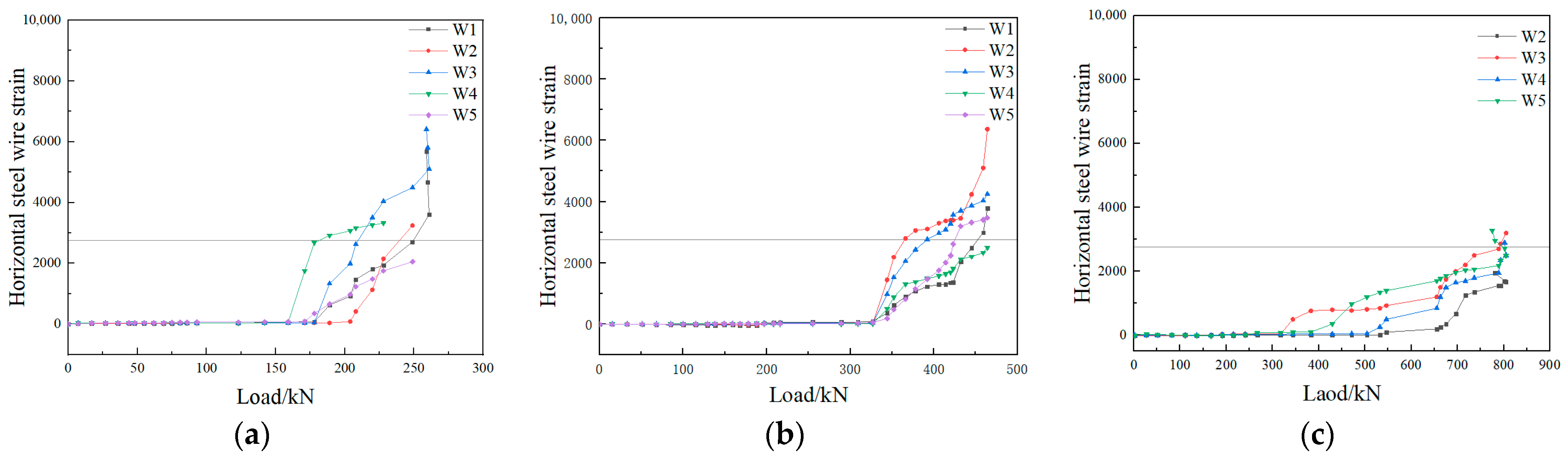
3.4. Analysis of Reinforcement Strain Test Results

Figure 10 shows the results of strain testing applied to the reinforcing bars positioned at the ends of some specimens.
Figure 10 shows that for specimens with a height-to-width ratio of 1.5:1 the steel bar yielded before it reached its ultimate load-bearing capacity. For specimens with height-to-width ratios of 1:1 and 1:2, when the ultimate load-bearing capacity was reached, the longitudinal reinforcement had also reached its yield state. Therefore, the longitudinal reinforcing steel played a significant role.
The results of strain tests applied to the horizontal steel wire in a typical specimen are shown in Figure 11.
Figure 11 shows that the strain tests applied to the horizontal steel wire mesh exhibited relatively large discreteness, and uneven stress could be observed, which was related to the location of the measuring point. The final strain measured at the crack was larger there. After oblique cracking occurred in the specimen, the strain in the steel wire at the position of the crack underwent a sudden change and reached its conditional yield point. At this point, even individual steel wires were broken, indicating that the steel wire mesh was subjected to a relatively large horizontal seismic force.

3.5. Test Results and Analysis of Lateral Bearing Capacity

The average values of ultimate load in the push and pull directions for each specimen were taken as the lateral bearing capacity of each specimen, and the average value of the lateral bearing capacity of two specimens from each group was taken as the lateral bearing capacity of that group; the results of the lateral bearing capacity tests are shown in Table 3. The test results showed that the lateral bearing capacity of a specimen was not only related to its cross-sectional area, but also to its height-to-width ratio and the vertical compressive stress applied. For specimens with the same height-to-width ratio, the higher the vertical pressure, the greater the lateral bearing capacity. The reason for this phenomenon can be analyzed as follows: Under the same lateral load, a larger vertical pressure results in a larger compression zone, which in turn reduces the tensile stress in the longitudinal reinforcement. Consequently, the reinforcement is less likely to yield, and the bending capacity of the specimen’s cross-section is improved.
Reference [20] carried out a seismic performance test on similar composite wall panels. Some specimens had a steel wire mesh anchorage, while others did not, and additional reinforcing bars were not provided in the wall panels. Through comparative test results, a prefabricated monolithic composite wall panel with reinforced steel bars, as presented in this paper, was compared to a wall panel without reinforced steel bars but with steel wire mesh anchorage. The lateral bearing capacity of the specimen with a height-to-width ratio of 1.5:1 increased by approximately 130%, while the lateral bearing capacity of the specimen with a height-to-width ratio of 1:1 increased by approximately 70%. Compared to specimens without anchorage and reinforcement, the lateral bearing capacity can be increased by approximately 160% when the height-to-width ratio is 1:2.
From the failure mode of the specimen, it was known that the precast and cast-in-place concrete were well combined without separation. The failure modes of the specimens resembled those of general reinforced concrete shear walls, meaning the bearing capacities of the former could be calculated with reference to the latter. In the calculation, only the effect of the concrete surface layer was considered, and the wall thickness was set as 100 mm. Due to the discontinuity between the upper and lower layers of vertical wires in the mesh and the lack of effective anchorage, the role of the wire mesh was not considered in the calculation of the bearing capacity of the normal section, and only the end reinforcing steel was considered. The calculation of shear in the oblique section should take into account the role of the horizontal steel wire in the steel wire mesh. Reference [22] provided the formula for calculating the bearing capacity of a reinforced concrete shear wall; the normal section bearing capacity of shear wall was calculated according to Equations (2)–(4), and the oblique section’s bearing capacity was calculated according to Equation (5). The test results showed that these equations were applicable to this specific situation.
N = A s f y A s σ s + α f c b w x
N ( e + h w o h w 2 ) = A s f y h w o α s + α f c b w x ( h w o x 2 )
e 0 = M N = V U H W N
V U 1 λ 0.5 0.5 f t b w h w 0 + 0.13 N A W A + f y h A s h S h w 0
When calculating the bearing capacities of wall panels according to the above formula, λ is the shear–span ratio, and λ = H h w o ; when λ ≤ 1.5, then λ = 1.5. V u is the ultimate load-bearing capacity of the specimen. f c is the axial compression strength of concrete (MPa), and f c = 23.48 MPa. f t is the axial tensile strength of concrete (MPa), and f t = 2.56 MPa. b w is wall panel thickness, which we gave a value of 100 mm.   h w o is the effective width of the wall panels; when h w o H , we assumed that h w o = H . H is the specimen height. f y h is the conditional yield strength of the steel wire (MPa), and f y h = 533 (MPa); A s h is the cross-sectional area of the horizontal steel wire in the mesh with the same cross-section (mm2); A s h = 14.14   m m 2 . S is the horizontal reinforcement spacing; S = 70 mm. f y is the yield strength of the reinforcement; f y = 428 MPa. σ s is the tensile reinforcement stress; if the steel bar yields, σ s = f y = 428 MPa. N is the vertical load applied to the wall panel. x is the height of the compression zone.
The lateral load bearing capacity was calculated using Formulas (2)–(4) and the theoretical values of lateral load bearing capacity were calculated using Formula (5) for each group of specimens that is shown in Table 3. The theoretical values of lateral bearing capacity for specimens should take the minimum value of the two, and the results are shown in Table 3.
As Table 3 shows, for the specimen with a height-to-width ratio of 1.5:1, the theoretical value of the lateral load capacity calculated for the normal section was much smaller than the theoretical value calculated for shear resistance, which was consistent with the failure mode of the specimen. The specimen first showed flexural failure, followed by diagonal shear damage. For a specimen with a height-to-width ratio of 1:1, the theoretical values of lateral bearing capacity calculated for its normal section and shear resistance were not very different, so diagonal shear failure and flexural failure occurred at almost the same time. For a specimen with a height-to-width ratio of 1:2, the theoretical value of the lateral bearing capacity calculated for the normal section was much larger than the theoretical value of the shear bearing capacity calculated according to the shear resistance, resulting in the specimen exhibiting only diagonal shear failure. According to Table 3, when considering the composite wall panel as a reinforced concrete shear wall, the calculated lateral load-bearing capacity based on the literature [22] was significantly lower than the experimental values. Thus, in practice, the lateral load-bearing capacity of the CPC panel can be conservatively evaluated using the calculation method of the reinforced concrete shear walls. In addition, it was known from the test results that the theoretical values of a specimen with a height-to-width ratio of 1.5:1 and 1:2 differed from their experimental values. The reason for this was that the theoretical bearing capacity of a specimen with a ratio of 1.5:1 was calculated according to the normal section, without considering the compression effect of the steel wire mesh. The strain test results on the reinforcing steel bar showed that when the specimen reached its ultimate load-bearing capacity, the reinforcing steel bar entered the strengthening stage. In addition, a 50 mm area of non-insulation material was present at the end of the specimen, which contributed to its bearing capacity. The specimen with a height-to-width ratio of 1:2 underwent shear failure. It was found that the partial horizontal steel wires of the steel mesh broke during shear failure. The theoretical value of the shear-bearing capacity, calculated according to the conditional yield strength, was small. The shear span ratio of the specimen was 0.5; thus, we can infer that when the shear span ratio is small, the lateral bearing capacity of the wallboard, calculated according to [22], will be sufficient.
From Table 3, it can be seen that the experimental values of each specimen were much higher than the theoretical values calculated according to [22], with large errors. The reason for this is that the load-bearing behavior of composite wall panels is complex, and there are many factors that affect their lateral load-bearing, especially for components with small height-to-width ratios that may experience shear failure. The shear effect can affect the load-bearing capacity of specimens [23,24,25,26]. Reference [22] is a technical standard for practical engineering design, and the calculation formula is based on experimental results with a certain safety margin. In particular, Formula (5) takes the lower envelope of the experimental results. Additionally, when calculating theoretical values according to [22], the strength of the steel reinforcement was taken as the yield strength, and when the specimens reached their ultimate load-bearing capacity, it exceeded the yield strength, indicating that the material strength used in theoretical calculations was slightly lower than expected. Additionally, the role of the insulation board was not considered, resulting in a significant discrepancy between the experimental and theoretical values. For practical engineering applications, the composite wall panels studied in this topic can be calculated based on [22] to meet the requirements and be considered safe.

4. Conclusions

Compared with a cast-in-place composite wall panel, the prefabricated monolithic composite wall panel can shorten the construction period and reduce the project cost. Compared with a prefabricated wall panel, it has better seismic performance. Through the quasi-static testing and theoretical analysis of 18 prefabricated monolithic composite wall panels, the following conclusions have been obtained:
(1)
The connectors spaced at 400 mm × 500 mm could ensure the concrete layers on both sides of the polystyrene board work collectively under seismic conditions In practical engineering, the spacing of connectors should not be greater than 400 mm.
(2)
The failure mode of the specimens is related to their height-to-width ratio and the number of reinforced steel bars. When 4C12 reinforced steel bars were set at both ends of a specimen with a height-to-width ratio of 1.5:1 and subjected to lateral loading, the longitudinal reinforcement at the end yielded first, followed by crushing of the concrete in the compression zone. Flexural failure occurred first, followed by diagonal shear failure in the diagonal direction along the main oblique cracks. For a specimen with an aspect ratio of 1:1, the shear failure caused by oblique cracks, the flexural failure caused by the yielding of tensile steel bars, and the crushing of concrete in the compression zone all occurred at almost the same time. A specimen with a height-to-width ratio of 1:2 ultimately underwent diagonal shear failure without flexural failure.
(3)
The installation of strengthened longitudinal reinforcements at the ends of the wall panels improved their lateral bearing capacity and deformation resistance, preventing them from slipping along the bottom and losing their bearing capacity. The magnitude of the raise was related to the height-to-width ratio of the wall panels, the vertical load on the wall panels, and the area of the reinforced steel bar. When the end reinforcing steel bars with 4C12 were installed, compared with the composite wall panel without reinforcing steel bars but with steel wire mesh anchorage measures, the lateral bearing capacity of the specimen with a height-to-width ratio of 1.5:1 increased by approximately 130%, while the lateral bearing capacity of the specimen with a height-to-width ratio of 1:1 increased by approximately 70%. Furthermore, compared to the specimens without anchorage and reinforcement, the lateral bearing capacity could be increased by approximately 160% when the height-to-width ratio is 1:2.
(4)
The lateral load-bearing capacity of the CPC panel can be conservatively evaluated using the calculation method of the reinforced concrete shear walls, with measured values exceeding theoretical values by 20–60%.
(5)
Specimens with large height-to-width ratios underwent flexural failure and exhibited good ductility, while specimens with small height-to-width ratios underwent diagonal shear failure and demonstrated poor ductility.

5. Future Work

Based on the above conclusions, in the future, we can study the seismic performance of this type of wall panel by exploring conditions such as adding different fibers, varying the specifications of the steel wire mesh, and investigating different connection methods between concrete panels and polystyrene boards. Shaking table tests can also be performed on the overall structural model using this type of wall panel. Additionally, the theoretical models proposed in references [27,28,29] regarding the behavior of cracked plate-like structures under dynamic loading are helpful for studying the vibration characteristics of structures. We also consider conducting research in this area in the future.

Author Contributions

Conceptualization, K.Z.; validation, Y.Z. and S.L.; investigation, Z.F., Y.X. and S.L.; data curation, Z.F. and Y.X.; writing—original draft preparation, Z.F.; writing—review and editing, K.Z., Y.Z., Y.X. and S.L.; supervision, K.Z. and Y.Z.; project administration, K.Z. All authors have read and agreed to the published version of the manuscript.

Funding

This research received no external funding.

Data Availability Statement

Data are contained within the article.

Conflicts of Interest

Authors Zijia Fan and Yufeng Xu were employed by the company Engineering Research Institute of Appraisal and Strengthening of Shandong Jianzhu University Co., Ltd. The remaining authors declare that the research was conducted in the absence of any commercial or financial relationships that could be construed as a potential conflict of interest.

References

  1. Li, H.; Wang, D.; Peng, L.; Zhou, J.; Zhang, C.; Wei, Q. Experimental study on wind resistance of autoclaved aerated concrete thermal insulation decorative composite exterior wallboard. Build. Sci. 2023, 39, 160–167. (In Chinese) [Google Scholar] [CrossRef]
  2. Zang, K.; Wang, Y. The advantages of GRC board exterior insulation composite wall. Brick 2007, 05, 55–56. (In Chinese) [Google Scholar] [CrossRef]
  3. Fernando, P.L.N.; Jayasinghe, M.T.R.; Jayasinghe, C. Structural feasibility of Expanded Polystyrene (EPS) based lightweight concrete sandwich wall panels. Constr. Build. Mater 2017, 139, 45–51. [Google Scholar] [CrossRef]
  4. Shin, D.H.; Kim, H.J. Composite effects of shear connectors used for lightweight-foamed-concrete sandwich wall panels. J. Build. Eng. 2020, 29, 101108. [Google Scholar] [CrossRef]
  5. Lei, S.; Wu, Z.; Zhang, C.; Huo, X.; Li, D. Experimental study on flexural performance of precast lightweight concrete thermal insulation exterior wallboard. Build. Technol. 2023, 54, 1611–1616. (In Chinese) [Google Scholar]
  6. Amran, Y.M.; Ali, A.A.; Rashid, R.S.; Hejazi, F.; Safiee, N.A. Structural behavior of axially loaded precast foamed concrete sandwich panels. Constr. Build. Mater. 2016, 107, 307–320. [Google Scholar] [CrossRef]
  7. Pavese, A.; Bournas, D.A. Experimental assessment of the seismic performance of a prefabricated concrete structural wall system. Eng. Struct. 2011, 33, 2049–2062. [Google Scholar] [CrossRef]
  8. He, Z.Z.; Pan, P.; Xiao, G.Q.; Shen, S.D.; Ren, J.Y. Test and analysis on axial performances of GFRP restraint connectors for sandwich insulation wall panels. J. Build. Eng. 2022, 45, 103457. [Google Scholar] [CrossRef]
  9. Sylaj, V.; Fam, A. UHPC sandwich panels with GFRP shear connectors tested under combined bending and axial loads. Eng. Struct. 2021, 248, 113287. [Google Scholar] [CrossRef]
  10. Pan, P.; He, Z.; Wang, H.; Kang, Y. Experimental investigation of C-shaped glass-fiber-reinforced polymer connectors for sandwich insulation wall panels. Eng. Struct. 2022, 250, 113462. [Google Scholar] [CrossRef]
  11. Choi, I.; Kim, J.; Kim, D.; Park, J. Effects of grid-type shear connector arrangements used for insulated concrete sandwich wall panels with a low aspect ratio. J. Build. Eng. 2022, 46, 103754. [Google Scholar] [CrossRef]
  12. Yan, M.; Wang, L.-G.; Chen, B.-L. Shear resistance and deflection prediction of steel–concrete–steel sandwich panel with headed stud connectors. Structures 2023, 54, 1690–1704. [Google Scholar]
  13. Lou, X.; Xue, W.; Bai, H.; Li, Y.; Huang, Q. Shear behavior of stainless-steel plate connectors for insulated precast concrete sandwich panels. Structures 2022, 44, 1046–1056. [Google Scholar] [CrossRef]
  14. Ma, S.; Hou, D.; Bao, P.; Wang, D. Influence of alkali-resistant glass fiber on seismic performance of precast ceramsite concrete sandwich wall panels. Structures 2022, 38, 94–107. [Google Scholar] [CrossRef]
  15. Ding, R.; Sun, Y.T.; Nie, X.; Chen, D.Q. Experimental study on seismic behaviour of an unreinforced precast wall-slab structure based on UHPC sandwich panels. J. Build. Eng. 2023, 68, 106197. [Google Scholar] [CrossRef]
  16. Kumar, S.; Chen, B.; Xu, Y.; Dai, J.G. Axial-flexural behavior of FRP grid-reinforced geopolymer concrete sandwich wall panels enabled with FRP connectors. J. Build. Eng. 2022, 47, 103907. [Google Scholar] [CrossRef]
  17. Huang, J.Q.; Dai, J.G. Flexural performance of precast geopolymer concrete sandwich panel enabled by FRP connector. Compos. Struct. 2020, 248, 112563. [Google Scholar] [CrossRef]
  18. Kumar, S.; Chen, B.; Xu, Y.; Dai, J.G. Structural behavior of FRP grid reinforced geopolymer concrete sandwich wall panels subjected to concentric axial loading. Compos. Struct. 2021, 270, 114117. [Google Scholar] [CrossRef]
  19. Sun, Q. Study on the Compressive Performance of Concrete Sandwich Composite Wall Panels. Ph.D. Thesis, Shandong Jianzhu University, Jinan, China, 2019. (In Chinese). [Google Scholar]
  20. Zhao, K.; Liu, M.; Huang, L. Experimental study on seismic performance of concrete sandwich composite slabs. Build. Struct. 2023, 53, 47–52. (In Chinese) [Google Scholar] [CrossRef]
  21. Zhao, K.; Li, J.; Wei, X. Experimental Study on the Mechanical Properties of Concrete-Polystyrene Composite Wallboard. J. Shandong Jianzhu Univ. 2023, 38, 9–16. (In Chinese) [Google Scholar]
  22. JGJ3-2010; Technical Specification for Concrete Structures of Tall Buildings. Construction Industry Press: Beijing, China, 2010. (In Chinese)
  23. Chen, C.S. Nonlinear vibration of a shear deformable functionally graded plate. Compos. Struct. 2005, 68, 295–302. [Google Scholar] [CrossRef]
  24. Kiani, K. Nonlocal and shear effects on column buckling of single-layered membranes from stocky single-walled carbon nanotubes. Compos. Part B Eng. 2015, 79, 535–552. [Google Scholar] [CrossRef]
  25. Kiani, K. Free vibration of in-plane-aligned membranes of single-walled carbon nanotubes in the presence of in-plane-unidirectional magnetic fields. J. Vib. Control. 2016, 22, 3736–3766. [Google Scholar] [CrossRef]
  26. Kiani, K.; Pakdaman, H. Nonlocal vibrations and potential instability of monolayers from double-walled carbon nanotubes subjected to temperature gradients. Int. J. Mech. Sci. 2018, 144, 576–599. [Google Scholar] [CrossRef]
  27. Liew, K.M.; Hung, K.C.; Lim, M.K. A solution method for analysis of cracked plates under vibration. Eng. Fract. Mech. 1994, 48, 393–404. [Google Scholar] [CrossRef]
  28. Nikkhoo, A.; Banihashemi, S.; Kiani, K. On non-stationary response of cracked thin rectangular plates acted upon by a moving random force. Sci. Iran. 2023. [Google Scholar] [CrossRef]
  29. Nikkhoo, A.; Banihashemi, S.; Kiani, K. Parametric investigations on dynamics of cracked thin rectangular plates, excited by a moving mass. Sci. Iran. 2023, 30, 860–876. [Google Scholar] [CrossRef]
Figure 1. Flow chart.
Buildings 14 00442 g001
Figure 2. The structure of CPC plate.
Buildings 14 00442 g002
Figure 3. Construction drawing of A-type (B-type, C-type) specimens.
Buildings 14 00442 g003
Figure 4. Test loading device.
Buildings 14 00442 g004
Figure 5. The relationship between the displacement and the number of cycles.
Buildings 14 00442 g005
Figure 6. Layout of measuring points.
Buildings 14 00442 g006
Figure 7. Specimen failure mode: (a) specimen A1-1, (b) specimen A2-2, (c) specimen A3-2, (d) specimen B1-2, (e) specimen B2-1, (f) specimen B3-1, (g) specimen C1-1, (h) specimen C2-2 (i) specimen C3-1.
Buildings 14 00442 g007aBuildings 14 00442 g007b
Figure 8. Hysteresis curves for (a) specimen A1-1, (b) specimen A1-2, (c) specimen A2-1, (d) specimen A2-2, (e) specimen A3-1, (f) specimen A3-2, (g) specimen B1-1, (h) specimen B1-2, (i) specimen B2-1, (j) specimen B2-2, (k) specimen B3-1, (l) specimen B3-2, (m) specimenC1-1, (n) specimenC1-2, (o) specimen C2-1, (p) specimenC2-2, (q) specimen C3-1, (r) specimen C3-2.
Buildings 14 00442 g008aBuildings 14 00442 g008b
Figure 9. The influence of various factors on the ductility coefficient.
Buildings 14 00442 g009
Figure 10. Reinforcement strain of specimens: (a) specimen A1-1, (b) specimen A2-2, (c) specimen B1-2, (d) specimen B3-1, (e) specimen C1-1, (f) specimen C3-1.
Buildings 14 00442 g010
Figure 11. Horizontal steel wire strain of specimens: (a) specimen A3−2, (b) specimen B3−1, (c) specimen C3−1.
Buildings 14 00442 g011
Table 1. Specimen number and requirements.
GroupsSpecimen NumberSize of Specimen (H × W) mmVertical Compressive Stress (MPa)Vertical Load (kN)
IA1-11500 × 10000.4080
A1-2
IIA2-11500 × 10000.80160
A2-2
IIIA3-11500 × 10001.20240
A3-2
IVB1-11500 × 15000.40120
B1-2
VB2-11500 × 15000.80240
B2-2
VIB3-11500 × 15001.20360
B3-2
VIIC1-11000 × 20000.40160
C1-2
VIIIC2-11000 × 20000.80320
C2-2
IXC3-11000 × 20001.20480
C3-2
Table 2. Ductility coefficient test results of specimens.
GroupsSpecimen NumberDuctility Coefficient rAverage Ductility Coefficient
IA1-16.36.6
A1-26.9
IIA2-15.25.0
A2-24.8
IIIA3-15.14.9
A3-24.7
IVB1-14.24.6
B1-24.9
VB2-13.94.1
B2-24.3
VIB3-14.03.7
B3-23.4
VIIC1-12.72.8
C1-22.8
VIIIC2-13.33.1
C2-22.8
IXC3-11.72.2
C3-22.6
Table 3. The ultimate load-bearing capacity test value and theoretical calculation value of the specimen.
GroupsIIIIIIIVVVIVIIVIIIIX
Experimental value V s u (kN)231.40248.45266.55334.30392.45431.55696.25815.05858.80
The theoretical value of lateral bearing capacity is calculated by Formulas (2)–(4) V u 1 (kN)141.47165.41187.54245.99299.86349.65545.08688.74821.51
The theoretical value of lateral bearing capacity is calculated by Formula (5) V u 2 (kN)226.14236.54246.94351.19366.79382.39476.24497.04517.84
The theoretical value of lateral bearing capacity of specimens V u (kN)141.47165.41187.54245.99299.86349.65476.24497.04517.84
V s u / V u 1.641.501.421.361.311.231.461.641.66
Disclaimer/Publisher’s Note: The statements, opinions and data contained in all publications are solely those of the individual author(s) and contributor(s) and not of MDPI and/or the editor(s). MDPI and/or the editor(s) disclaim responsibility for any injury to people or property resulting from any ideas, methods, instructions or products referred to in the content.

