Article

High-Temperature Behavior of Carbon Reinforced Concrete

1
Faculty of Civil Engineering, Leipzig University of Applied Sciences (HTWK Leipzig), 04251 Leipzig, Germany
2
Faculty of Civil Engineering, IU International University of Applied Sciences, 01067 Dresden, Germany
*
Author to whom correspondence should be addressed.
Buildings 2024, 14(2), 364; https://doi.org/10.3390/buildings14020364
Submission received: 15 October 2023 / Revised: 22 December 2023 / Accepted: 24 January 2024 / Published: 29 January 2024
(This article belongs to the Special Issue Research on the Performance of Non-metallic Reinforced Concrete)

Abstract

:
Carbon reinforced concrete is perceived by industry as a promising alternative to the currently established construction products. Previous building authority approvals and approvals for this construction method largely exclude questions of preventive fire protection with regard to load-bearing behavior under fire because there are hardly any reliable research results available in this field. This article shows the results of experimental investigations including thermogravimetric analyses of carbon reinforcement and tensile tests on the composite material carbon reinforced concrete. The thermogravimetric analyses show the loss of mass of the carbon reinforcement under a temperature load. A decomposition of the coating system of the carbon fibers and, with increasing temperature load, also of the carbon was observed. By varying various boundary conditions, such as the heating rate and the oxygen content present, their influences can be assessed. Stationary and non-stationary tensile tests on strip-shaped carbon reinforced concrete specimens were used to determine the load-bearing and deformation behavior in the high-temperature range up to 700 °C. The investigations were carried out under constant heating rates of 2 K/min and 10 K/min. This made it possible to obtain stress-strain curves and information on the various temperature-dependent deformation components from mechanical strains and load-independent strains. The time- and temperature-dependent decomposition of the carbon resulted in a reduction in the tensile load-bearing capacity of the reinforcement in the high-temperature range. This effect can be taken into account by considering the cross-sectional loss of the carbon reinforcement in a hot design.

1. Introduction

Carbon reinforced concrete is a high-strength composite material consisting of a mineral matrix with embedded carbon reinforcement. High-performance carbon fibers are used as reinforcement due to their high load-bearing capacity. The investigations by [1,2,3,4] are the basis of the characterization of the tensile behavior of concrete reinforced with textiles at normal temperature. For this purpose, uniaxial tensile tests were performed. It was shown that the interaction of the materials involved and their characteristic values, such as the cross-sectional area, the stiffness and strength, as well as the composite properties between the fibers and between fiber and matrix influence the load-bearing behavior. Influences from the manufacture of textile reinforcements can also have effects. According to Lorenz et al. [5], a waviness of the yarns in the textile can lead to additional deformations and spalling of the concrete cover due to deflection forces.
The material carbon is not resistant under atmospheric conditions in the high-temperature range. From a temperature of approx. 500 °C, an oxidation reaction of the carbon start: see [6,7,8]. This reaction leads to a loss of substance with the release of carbon dioxide and carbon monoxide: see [9]. The temperature range at which oxidation begins depends on various influencing factors, such as the carbon fiber precursors and the process temperature during fiber production, which defines the modulus of elasticity of the fibers: see [10]. Refs. [11,12,13] have found that initial oxidation reactions can begin even at lower temperatures of about 300 °C and higher. Further influencing factors on the oxidation behavior are the fiber diameter and the maximum temperature [14,15]. According to Hennig [16] and Long [13], various elements or substances such as alkali metals, platinum, silver oxides, and boron act as catalysts which accelerate the oxidation reaction of carbon.
So far there have been only a few investigations on the fire behavior of carbon reinforced concrete. For thin-walled one-sided flamed I-profiles, Krüger et al. [17] showed a dependence of the component behavior on the fiber material used for the textile and the behavior of the concrete at high temperatures. Flaking of the fine concrete and a failure of the textile reinforcement were observed and the fire resistance class R30 was achieved.
Brameshuber et al. [18] carried out fire tests with one-sided flaming on 10 mm thick lost textile concrete formwork with a 10 cm top-up concrete supplement of normal concrete on undamaged (non-cracked) specimens without static load during the fire. The space-closing function was not influenced, but spalling occurred in the plane of the composite joint (“sloughing off”) as well as explosive spalling up to 2 cm deep into the top concrete. The fire resistance class reached was R30.
Ehlig et al. [19] showed the tensile behavior of carbon reinforced concrete under direct flame treatment according to the unit temperature curve based upon ISO 834 [20]. For this purpose, test specimens with dimensions of 1000 mm × 60 mm × 8 mm were produced and directly flamed on all sides in the small test rig. As textile reinforcement, carbon filament yarns with a fineness of 800 tex were used and installed in different numbers of layers (2, 3 and 4). During flame treatment, the test specimens were subjected to different load levels (16.5%, 33%, 50%, and 62.5% of the load capacity). The specimens showed an increase in deformations under flame exposure. After 4 to 5 min of temperature loading, large-area, partially explosive spalling occurred. The failure occurred after 5 to 15 min due to tensile fracture of the exposed reinforcement depending on the load level.
Based on these findings, this publication presents experimental investigations showing the mass loss of carbon fibers in the high-temperature range and the tensile behavior of carbon reinforced concrete under temperature stress.

2. Investigations on the Mass Change of the Textile Carbon Reinforcement under Temperature Load

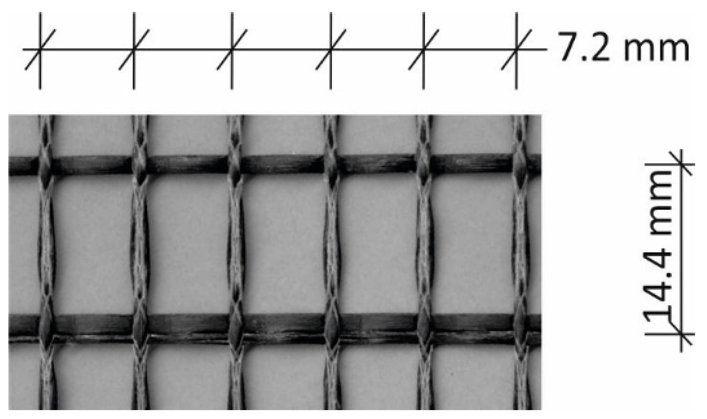
2.1. Specimens and Test Procedure

Thermogravimetric analyses (TGA) were performed to determine the mass loss of the textile carbon reinforcement under temperature loading [21]. The mass change was determined as a function of temperature and time under defined environmental conditions. For a realistic reference, air was selected as the general environment and nitrogen as the comparison to prevent oxidation of the carbon. The temperature increase took place under a constant heating rate of 2 K/min or 10 K/min. Approximately 20 mg of the textile reinforcement was heated per test.
As textile reinforcement, stitch-bonded fabrics of carbon filament yarns with a fineness of 800 tex (1 tex = 1 g/km) were investigated. The warp knitting technique used was developed mainly by HAUSDING [22]. The distance between the filament yarns in warp direction amounts 7.2 mm and in weft direction 14.4 mm (see Figure 1). The statically effective reinforcement area of the filament yarn is At = 0.45 mm2.
The textile reinforcement was tested uncoated and coated with an aqueous dispersion based on self-crosslinking, carboxylated styrene-butadiene copolymers (SBR) according to Mäder et al. [23]. The coating content is 18%.

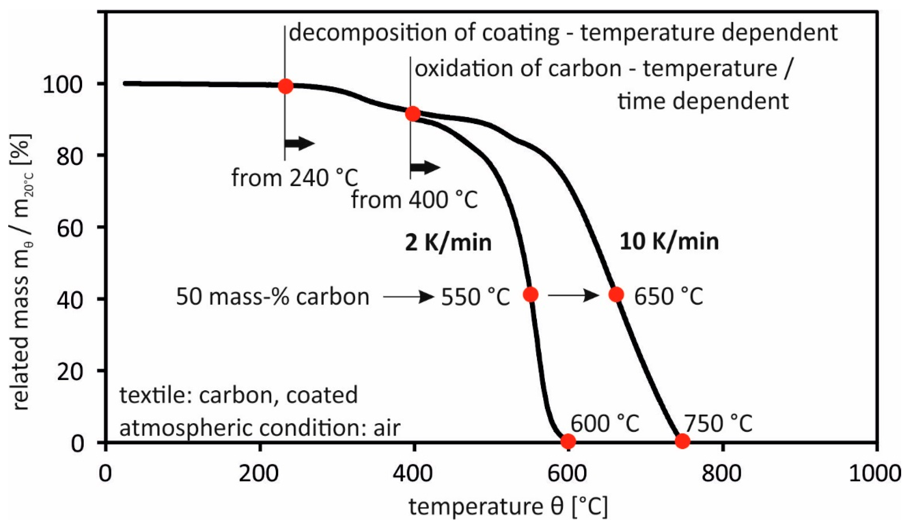
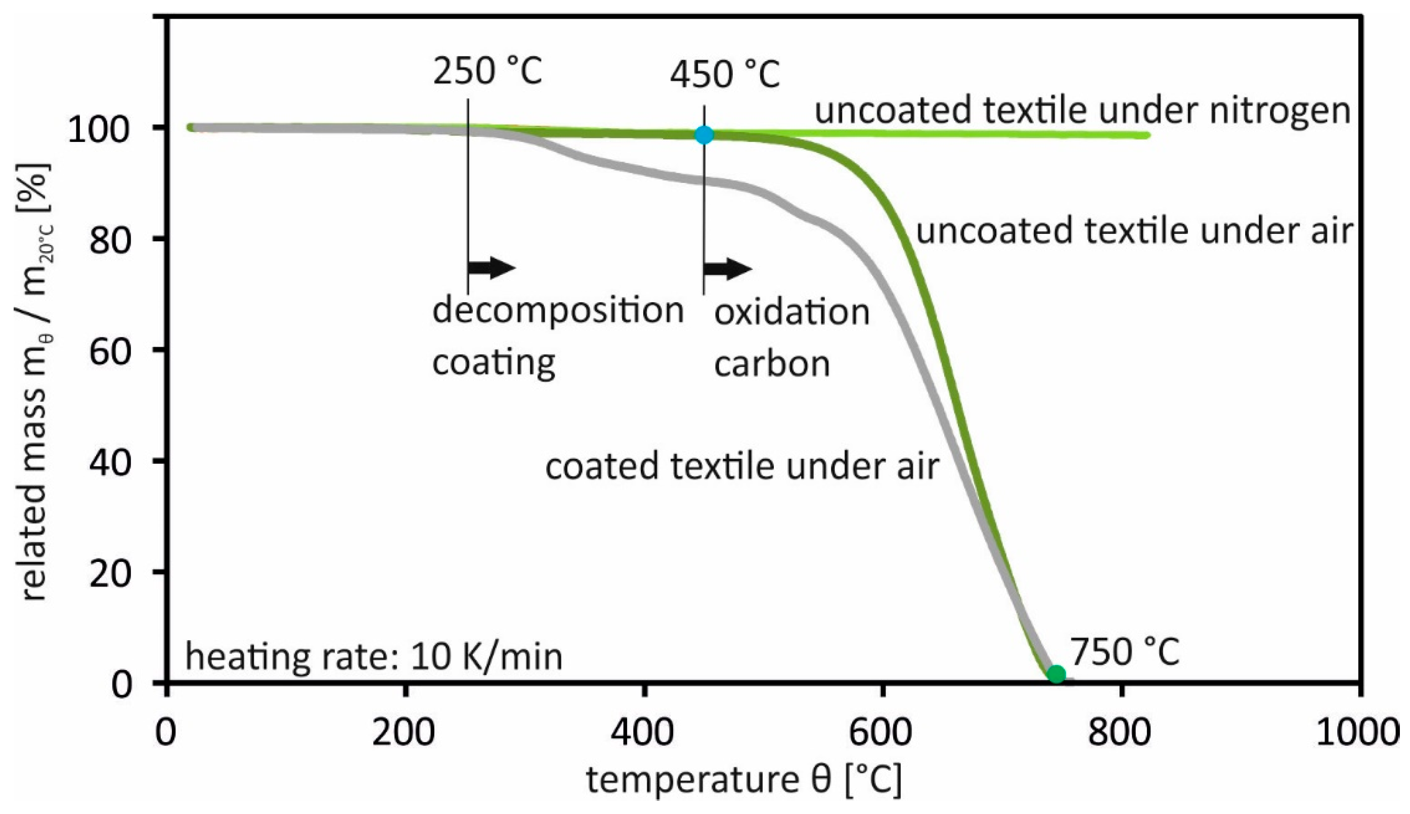
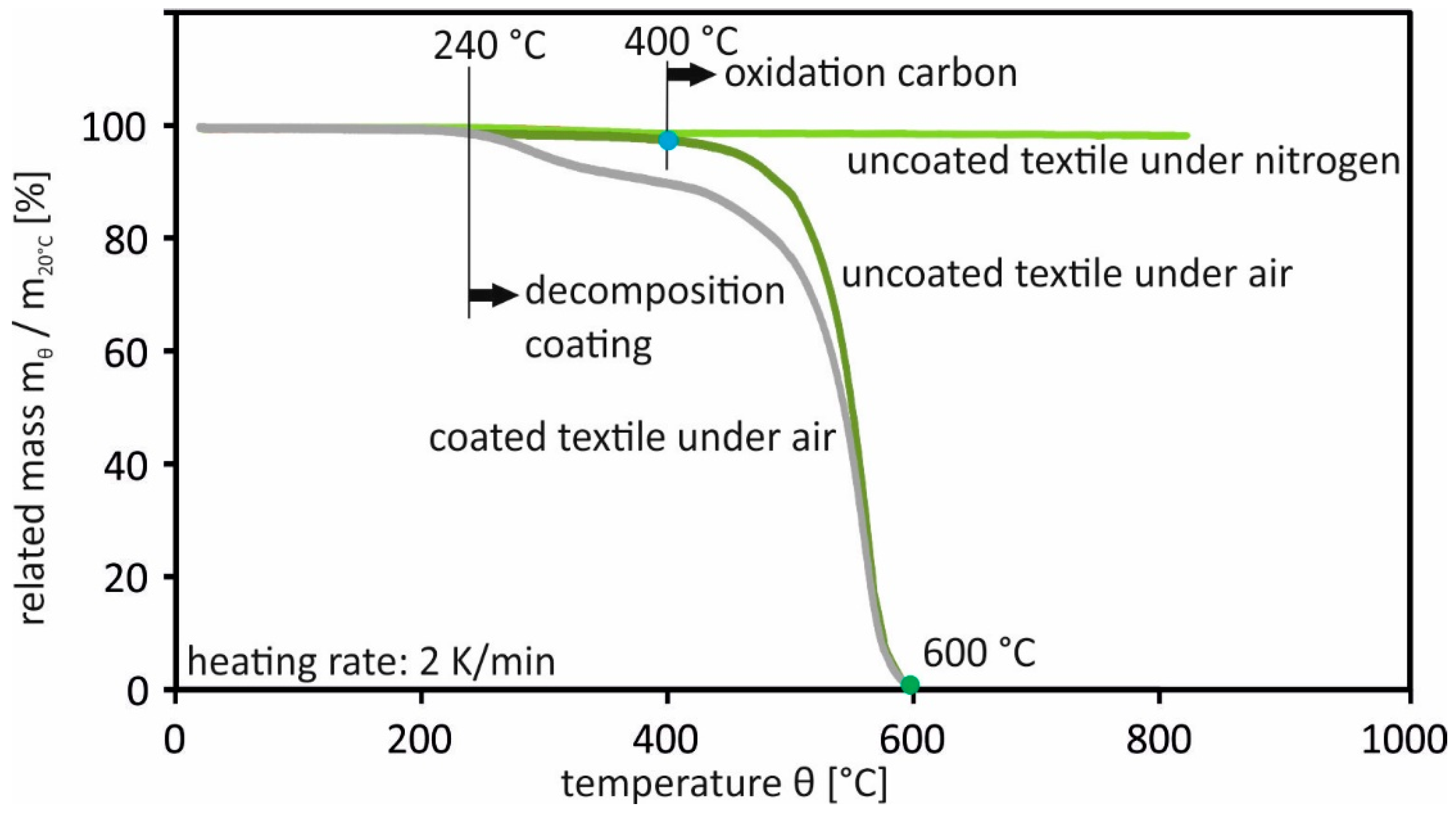
2.2. Results of the Experimental Investigations

In the following, the relevant temperatures are considered in connection with the duration of the temperature load and the heating rate. For this purpose, the mass loss under air atmosphere of the coated textile reinforcement above the temperature at a heating rate of 2 K/min as well as 10 K/min is plotted in Figure 2. The program shows the results of individual tests. The mass loss curves can be divided into two areas:
  • Evolution of decomposition of the coating until start of oxidation of the carbon:
Up to approx. 240 °C, there is only a slight loss of mass of approx. 1.5%. This increases with increasing temperature load, whereby the decomposition of the coating is temperature-dependent but independent of the heating rate of the temperature load.
  • Beginning of oxidation of the carbon until complete decomposition of the textile reinforcement:
Experiments with uncoated textiles yielded information on the course of the mass loss due to the oxidation of the carbon: see Figure 3 and Figure 4. It was observable that no oxidation reaction of the carbon occurs under nitrogen due to the lack of oxygen.
The oxidation of the carbon under oxygen begins at a heating rate of 2 K/min at 400 °C and 10 K/min at 450 °C. The temperature of the carbon then is heated to 2 K/min at 400 °C and 10 K/min at 450 °C, respectively. The course of the oxidation reaction shows a small loss of mass at the beginning and a disproportionate increase with increasing temperature load. The reaction depends on time and temperature. An increase in the heating rate causes faster decomposition of the carbon over time. Complete decomposition of the carbon occurs at temperatures below 750 °C and 600 °C respectively.
However, no information about the load-bearing behavior can be derived directly from the experiments. Therefore, tensile tests were carried out on carbon reinforced concrete specimens. Under different combinations of static and thermal loading, fundamental questions regarding the load-bearing and deformation behavior as well as the failure mechanisms have to be answered.

3. Investigation of the Tensile Behavior of Carbon Reinforced Concrete under Temperature Stress

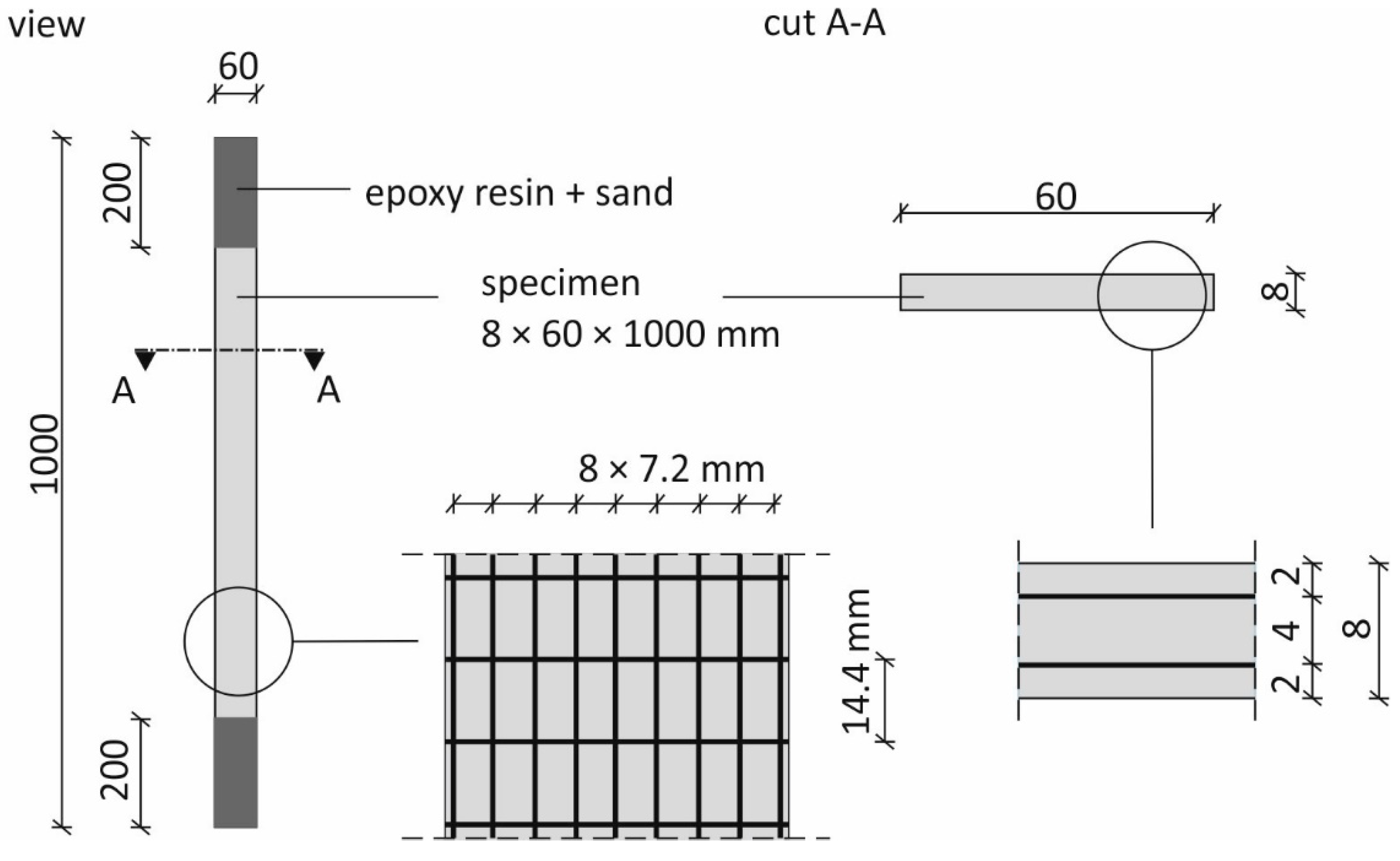
3.1. Material and Specimens

Carbon reinforced concrete slabs with dimensions of 1.20 m × 0.7 m × 8 mm were initially produced for the production of the test specimens. The cut-to-size textile reinforcement pieces were first coated with epoxy resin over a length of approx. 200 mm in the end clamping areas and embedded in sand. This served to improve the bond in order to avoid bond failure, compare [24]. Then, the panels were manufactured using a manual lamination process into a smooth, non-absorbent steel formwork. After the application of an approx. 3 mm thick first fine concrete layer, the first textile layer was installed by gently pressing the textile fabric into the fine concrete matrix with the aid of a smoothing trowel. After the application of another 3 mm thick fine concrete layer, the second textile layer was applied in the same way, and a final 2 mm thick layer of fine concrete resulted in a total slab thickness of approx. 8 mm. The formulation of the fine concrete used is based on research by Curbach and Jesse [25] and is shown in Table 1.
To prevent the fresh concrete from drying out, the concrete surfaces of the slabs were covered with damp cloths and foil after concreting. After three days, the slabs were stripped and stored under water at approx. 20 °C until the seventh day, followed by storage in a climatic chamber at 20 °C and 65% relative humidity. After about 21 days, ten specimens were sawn from each plate. The specimen shape and geometric dimensions as well as the arrangement of the textile reinforcement are shown in Figure 5.
The mechanical properties of the fine concrete listed in Table 2 were determined on prismatic specimens measuring 40 mm × 40 mm × 160 mm. The storage and post-treatment of the prisms were carried out in the same way as for the carbon reinforced concrete specimens. The specimen’s age was 28 days.

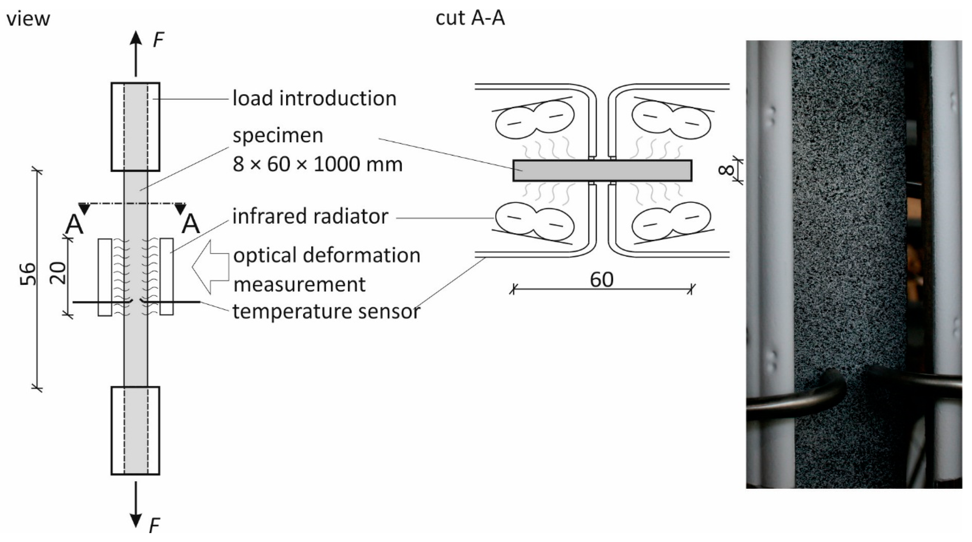
3.2. Experimental Setup and Test Program

To carry out the tensile tests under normal and elevated temperatures, the specimen was installed in a servohydraulic testing machine with a capacity of 100 kN. In order to ensure a constant introduction of forces into the specimen over the entire cross-section, load distribution devices were attached to the upper and lower ends of the specimen. The main components of these devices are two steel plates between which the specimen was clamped. Between the steel plates and the specimen surface, there was a 0.5 mm thick rubber leveling layer to avoid local stress peaks, e.g., due to unevenness of the concrete surface. The contact pressure was selected to prevent the sample from slipping within the load application. The compressive strength of the sample was not exceeded. The load introduction length was 220 mm. This resulted in a free specimen length of 560 mm: see Figure 6. To align and stabilize the specimen, a preload of approx. 0.2 kN was applied and kept constant during the stationary tests. The temperature load was applied in the middle part of the free sample length in a range of approx. 200 mm by means of four short-wave twin-tube infrared radiators made of quartz glass with nanoreflector (IR radiator). The arrangement of the IR radiators is shown schematically in the cross-sectional view A-A in Figure 6. In addition, insulation boards on the sides and insulation wool in the upper area of the test stand were installed to protect the test equipment and to separate the two IR radiators belonging to the test specimen surfaces and to minimize air circulation.
The load and displacement of the testing machine heads were measured by a load cell and an inductive displacement transducer integrated in the loading frame. The temperatures were measured with temperature sensors type K (NiCr-Ni) selectively on the specimen surface. In each case, one temperature sensor controlled the IR radiator setup for the area. The deformations in the temperature load area were measured using 3D photogrammetry on a measuring field of 60 × 140 mm2 on one side of the sample. In all tests with temperature loading, the test specimens were pre-damaged by a tensile load of 65% of their load capacity. This was conducted immediately before the actual temperature test in the same test rig, i.e., without additional removal or installation of the specimen. This created a uniform crack pattern of the specimen at the start of the test and thus made it possible to compare the tests with each other, regardless of the degree of loading during heating. The test program comprised stationary and non-stationary temperature tests. In the stationary tests, the pre-damaged statically unloaded specimen was heated at a constant heating rate of 2 or 10 K/min to a predetermined test temperature. The test specimens were positioned in such a way that, during the heating phase, no stresses were generated as a result of thermal expansion. After the heating phase, the target temperature was kept constant until all the specimen’s volumes arrived at a constant temperature distribution. A tensile load was then applied in a displacement-controlled manner and the resulting force measured. In addition to the stationary tests, non-stationary warm creep tests were carried out, which represent the real conditions of a fire event: compare [26,27]. In these tests, the specimens were loaded with a tensile force of 25%, 35%, 50%, 65%, and 75% of the reference tensile strength and then heated with 2 K/min or 10 K/min until failure. The static load was kept constant during the temperature load.

4. Results and Discussion

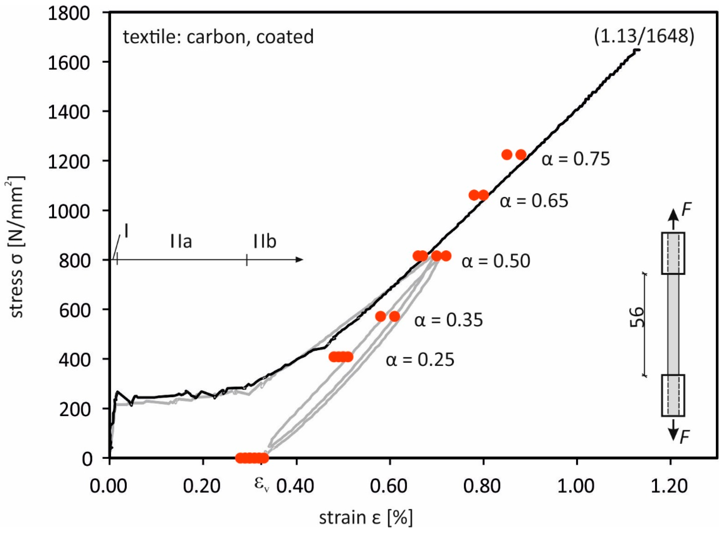
4.1. Load-Bearing Behavior at Normal Temperature

Reference tests were used to determine the load-bearing behavior at normal temperature. Figure 7 shows an example of the stress–strain curve of such a test. The typical tensile behavior for carbon reinforced concrete can be seen, consisting of the areas state I (non-cracked), state IIa (multiple crack formation), and state IIb (completed crack formation).
The maximum elongation for the test shown is 1.13%, with a maximum load of 1648 N/mm2. The mean values of elongation and stress at failure over all reference tests are 1.12% and 1633 N/mm2. Figure 7 was supplemented with the course of the hysteresis loops from the previous damage. Due to the respective applied load level of α = 0.65, the test specimens reached state IIb, so that at the beginning of the temperature load a complete crack pattern was present. The specimens showed a fine crack pattern with distances between 15 mm and 25 mm. The applied pre-damage causes a plastic elongation εv between 0.29% and 0.55%. This could be measured in the relieved state and is a measure of the manufacturing-related waviness in the textile structure.

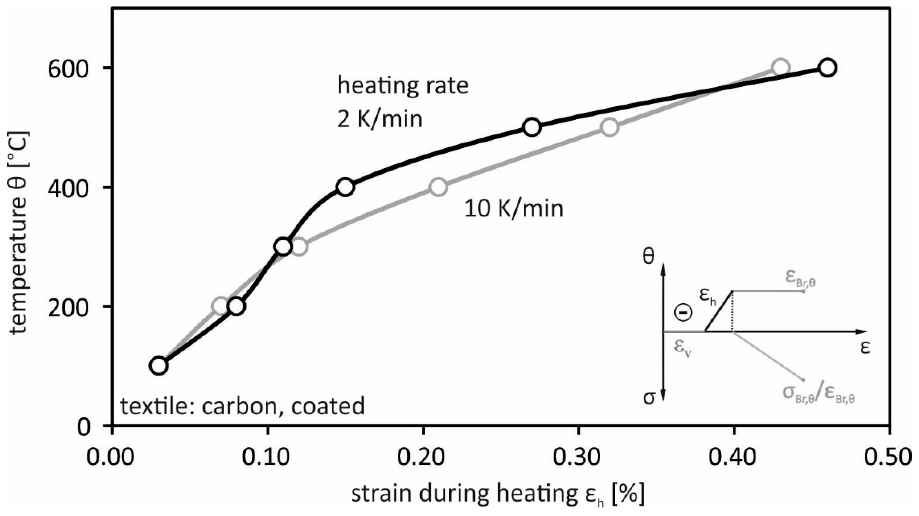
4.2. Load-Independent Strains from the Stationary Tests

According to Kordina and Meyer-Ottens [28] and Schneider [29], the load-independent strains derive from the heating phase of the stationary experiments. Figure 8 shows mean values from 16 tests of these strains above the temperature of the considered heating rates.
It can be seen that the strains increase with increasing temperature. A significant dependence between the considered heating rates could not be determined. However, the measured expansion of the composite sample does not correspond to the thermal behavior of the material carbon. At room temperature, for carbon, the coefficient of expansion is negative in the range from −0.05 to −0.3–10−6 K−1 and increases with increasing temperature into the positive range up to 2.5–10−6 K−1 at 2400 °C [30]. This suggests that additional effects influence the expansion during heating, for example from design faults, such as the waviness of the filaments in the yarn from textile production and/or component production or due to the interaction of carbon and concrete, which has a higher thermal coefficient of expansion [31].
Since no direct measurement of the deformations of the carbon reinforcement was carried out, but rather a measurement of the concrete surface, it cannot be ruled out that constraining stresses due to the prevented expansion between reinforcement and concrete matrix could occur. However, a measured increase in the crack width and an extension of the entire specimen during heating, measured by the machine path, allow for the assumption that a largely free expansion of the individual components of the composite was possible.

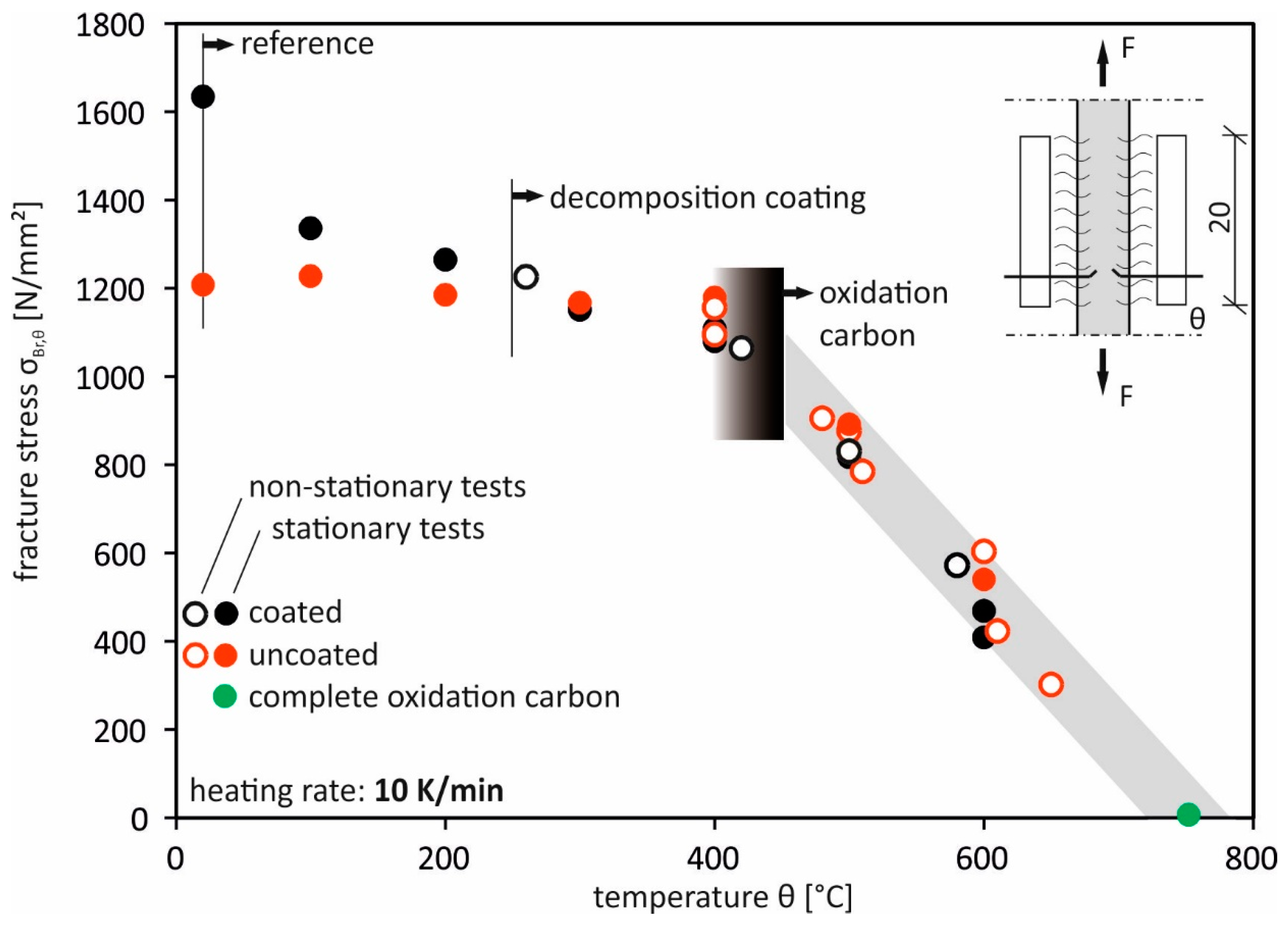
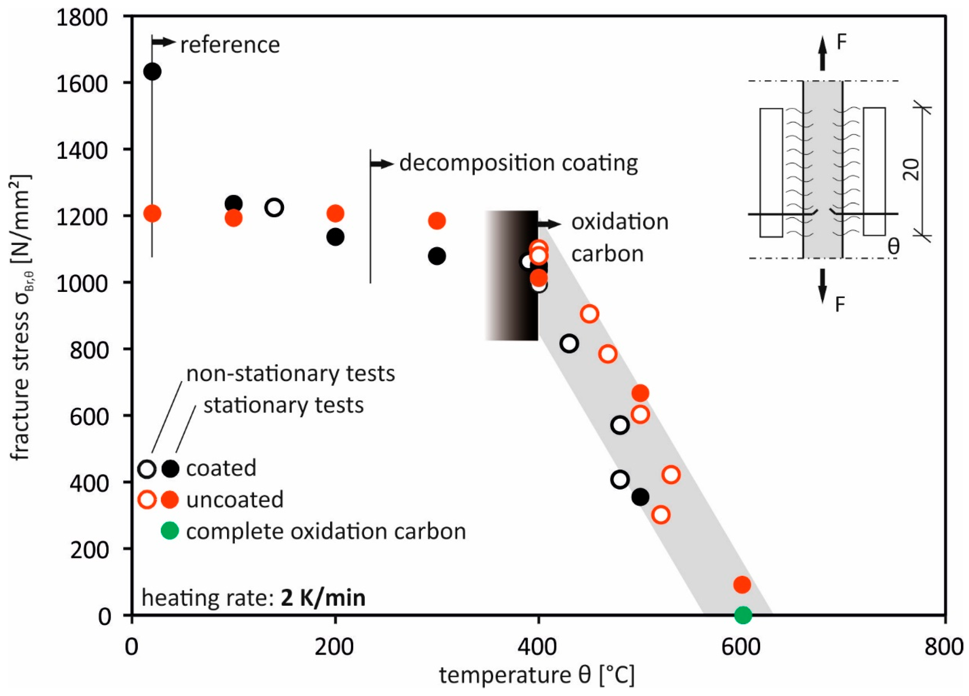
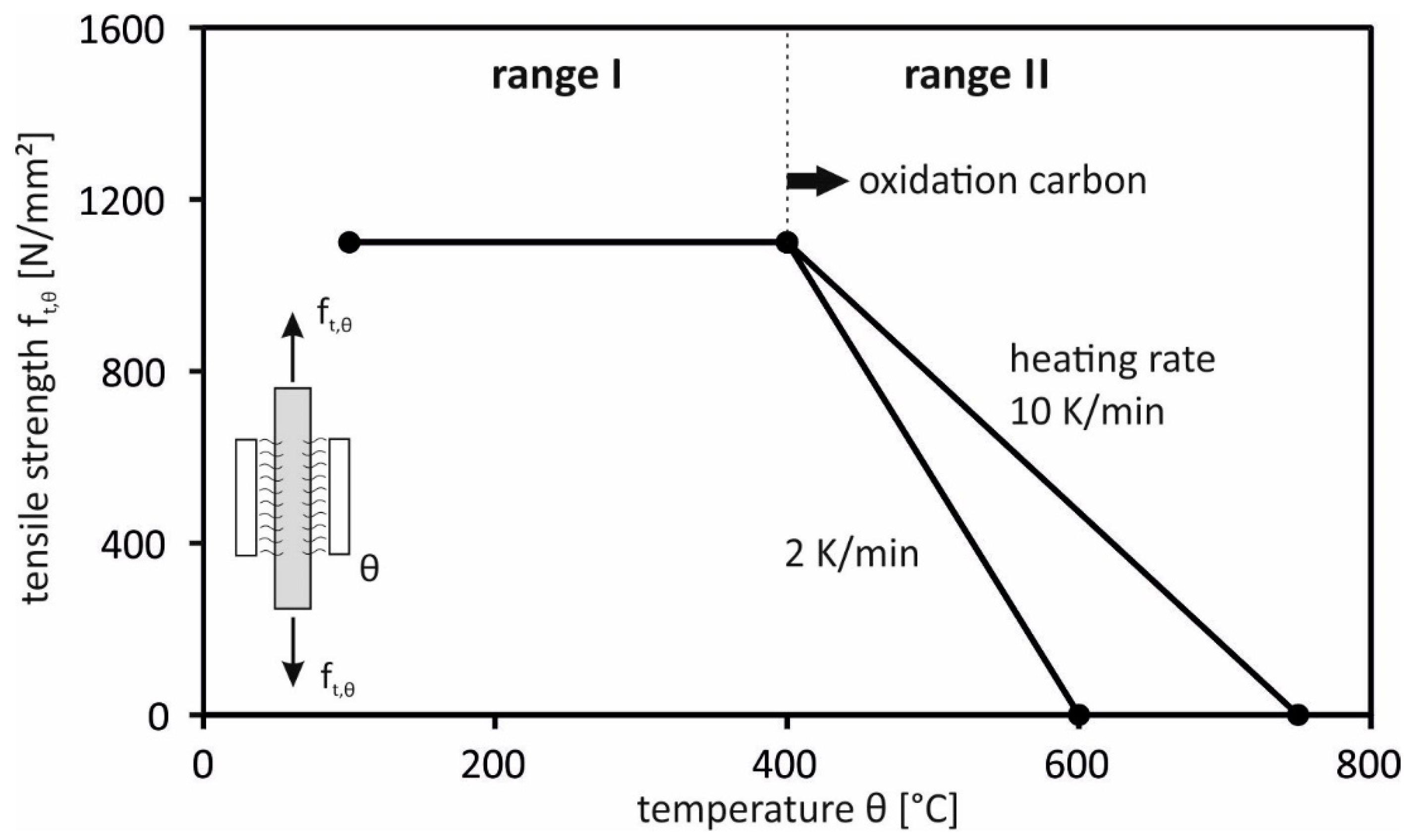
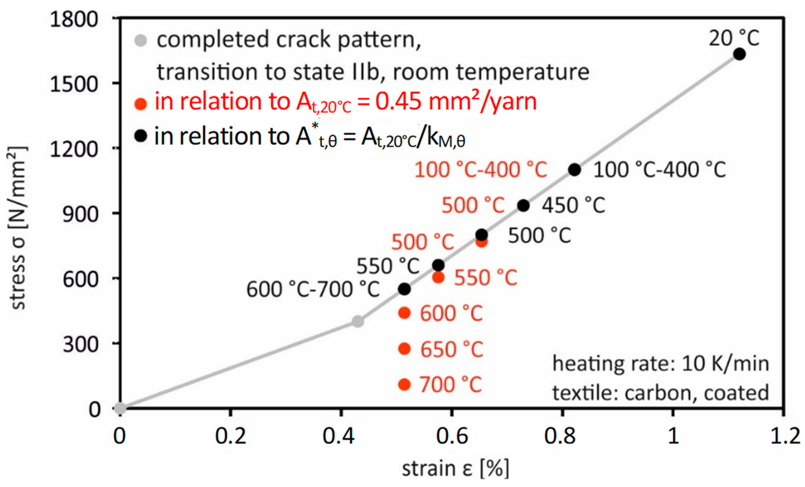
4.3. Tensile Carrying Capacity

The failure of all tested specimens occurred due to tensile failure of the textile reinforcement within the temperature load range. The measured breaking stresses of the stationary and non-stationary tests are plotted in Figure 9 for the heating rate of 10 K/min and in Figure 10 for 2 K/min. The course of the fracture stress over the temperature can be divided into the following two ranges:
  • Temperatures up to 400 °C:
Starting from the reference tests under normal temperature up to 400 °C, i.e., the starting temperature for the carbon oxidation from the TGA tests, a material behavior dependent on the textile configuration was observed. In the samples with uncoated textiles, no or only a small drop in the load-bearing capacity could be determined, while the results of the coated structure dropped below the load-bearing capacity as the temperature load raised up. As in the TGA tests, there is no dependence on the heating rate in this area.
  • Temperatures from 400 °C to the temperature of complete loss of load-bearing capacity:
In this temperature range, an almost straight-line drop in load-bearing capacity was observed, independent of the load level α, up to a temperature which, according to the TGA tests, corresponds to the complete decomposition of the carbon. This temperature depends on the heating rate and was 750 °C at a temperature load of 10 K/min and 600 °C at 2 K/min.
It should be noted that the stresses refer to the cross-sectional area of the carbon filament yarns at normal temperature and not to a cross-section reduced by the oxidation reaction. The actual stresses of the reinforcement are higher by the ratio of the area of the initial cross-section to the non-oxidized cross-section.

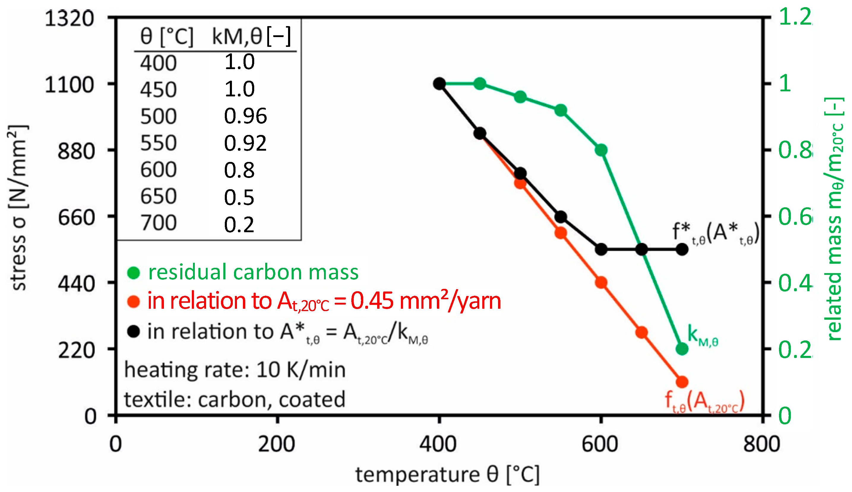
4.4. Derivation of Temperature-Dependent Material Parameters

The tensile strength behavior can be divided into two temperature ranges: see Figure 11. In range I between room temperature and 400 °C, the tensile strength can be assumed to be ft,θ = 1100 N/mm2, which is comparable to an uncoated textile configuration. An SBR coating that increases the load under room temperature is lost in this temperature range. The heating rate of the temperature load has no significant influence.
In range II, a load loss occurs with increasing the temperature load, which is dependent on the respective heating rate. The course of the tensile strength over the temperature decreases linearly until complete decomposition of the carbon. The factors for the different mass loss under the heating rates considered were not the subject of the investigations. The observed behavior could be a function of the different chemical kinetics or the different temperature values that the fibers experience during the thermal load. As mentioned before, the oxidation of the carbon in area II results in a reduction in the cross-sectional area of the carbon filaments. This reduction can be derived from the described thermogravimetric analyses (TGA) under atmospheric conditions and indicated by a temperature-dependent factor kM,θ. In this case, kM,θ = 1.0 corresponds to the initial mass of the carbon without coating. Figure 12 shows the factor kM,θ, the tensile strength ft,θ and the strength f*t,θ for a heating rate of 10 K/min. The tensile strength f*t,θ is calculated taking into account the reduced cross-section. It can be seen that, despite consideration of the mass loss of the carbon, a load loss of about 50% to approx. 550 N/mm2 occurs in the temperature range between 400 °C and 600 °C. This is due to the fact that the carbon has a reduced tensile strength of approx. 50%.
Figure 13 shows the schematic stress–strain curves of the tensile tests of the coated carbon textile reinforcement at normal temperature. The fracture stresses in red as well as the associated mechanical fracture strains of the tests under temperature load are supplemented. The fracture stress refers to the initial reinforcement area At,20°C = 0.45 mm2/carbon yarn (red dots). The mechanical elongations result from the total elongation minus the load-independent elongation during heating. It can be seen that the mechanical strains up to temperatures of around 500 °C are identical to the strain curve under normal temperature. As the temperature load further increases up to 600 °C, there is a decrease in elongation at the rupture, deviating from the stress–strain curve at normal temperature. The elongation at the rupture remains almost constant at above 600 °C.
Using reduced cross-sections, determined from thermogravimetric analyses (black dots), tensile strengths f*t,θ are obtained where the stress–strain curves are similar to those at normal temperature. This allows the temperature load due to the loss of cross-sectional area to be taken into account. The remaining cross-sectional area of the reinforcement has the same modulus of elasticity as under normal temperature.

5. Conclusions

The thermogravimetric analyses show a temperature-dependent decomposition of the coating of styrene-butadiene copolymers under air atmosphere from 240 °C as well as a temperature- and time-dependent oxidation of the carbon from 400 °C. Under inert atmospheric conditions, no oxidation of the carbon takes place up to temperatures of 800 °C. The carbon then is oxidized at a temperature of up to 400 °C. Decomposition of the coating cannot be prevented. With regard to the tensile behavior of carbon reinforced concrete, it was found that the polymer coating of the textiles used decomposes up to temperatures of 400 °C and the load-bearing capacity drops to a comparable level for uncoated textiles. An influence of the heating rate is not discernible in this temperature range. Above 400 °C, the incipient oxidation reaction of the carbon causes an increasing loss of load-bearing capacity as the temperature rises. The heating rate thus influences the fire resistance duration. The stress–strain curves drawn up using mechanical strains show that, up to temperatures of about 500 °C, the modulus of elasticity corresponds to that at normal temperature. Above 500 °C, the modulus of elasticity decreases. The results of the various strain components show that, during the heating phase, the different thermal strains of the various building materials do not lead to any constraining stresses that influence the load-bearing behavior of the composite material.

Author Contributions

Conceptualization, D.E. and A.S.; methodology, D.E.; software, D.E.; validation, D.E., A.S. and L.N.; formal analysis, D.E.; investigation, D.E. and A.S.; resources, D.E. and L.N.; data curation, D.E.; writing—original draft preparation, D.E.; writing—review and editing, A.S. and L.N.; visualization, D.E.; supervision, D.E.; project administration, D.E.; funding acquisition, D.E. All authors have read and agreed to the published version of the manuscript.

Funding

The research work presented in the publication has been funded by the Deutsche Forschungsgemeinschaft (DFG, German Research Foundation)—SFB 528; Project-ID: 5483454.

Data Availability Statement

The data presented in this study are available on request from the corresponding authors. The data are not publicly available due to privacy.

Conflicts of Interest

The authors declare no conflict of interest. The funders had no role in the design of the study; in the collection, analyses, or interpretation of data; in the writing of the manuscript; or in the decision to publish the results.

References

  1. Jesse, F. Tragverhalten von Filamentgarnen in Zementgebundener Matrix. Ph.D. Thesis, Technische Universität Dresden, Fakultät Bauingenieurwesen, Dresden, Germany, 2004. [Google Scholar]
  2. Eckers, V.; Gries, T. Entwicklung eines Prüfplans für Bewehrungen für Textilbeton. Bautechnik 2012, 89, 754–763. [Google Scholar] [CrossRef]
  3. Brameshuber, W. RILEM TC 232-TDT: Uniaxial tensile test—Test method to determine the load bearing behaviour of tensile specimens made of Textile Reinforced Concrete. Mater. Struct. 2016, 49, 4923–4927. [Google Scholar]
  4. Lorenz, E.; Schütze, E.; Weiland, S. Textilbeton—Eigenschaften des Verbundwerkstoffs. Beton Stahlbetonbau 2015, 110, 29–41. [Google Scholar] [CrossRef]
  5. Lorenz, E.; Ortlepp, R.; Hausding, J.; Cherif, C. Effizienzsteigerung von Textilbeton durch Einsatz textiler Bewehrungen nach dem erweiterten Nähwirkverfahren. Beton Stahlbetonbau 2011, 106, 21–30. [Google Scholar] [CrossRef]
  6. Manocha, L.M.; Manocha, S. Studies on solution-derived ceramic coatings for oxidation protection of Carbon-Carbon composites. Carbon 1995, 33, 435–440. [Google Scholar] [CrossRef]
  7. Wang, Y.Q.; Zhou, B.L.; Wang, Z.M. Oxidation protection of Carbon fibers by coatings. Carbon 1995, 33, 427–433. [Google Scholar] [CrossRef]
  8. Spaseska, D. The thermal behaviour of low-temperature produced carbon fibres for a special application. Bull. Chem. Technol. Maced. 1995, 18, 179–185. [Google Scholar]
  9. Hatta, H.; Aoki, T.; Kogo, Y.; Yarii, T. High-temperature oxidation behavior of SiC-coated carbon fiber reinforced carbon matrix composites. Compos. Part A 1999, 30, 515–520. [Google Scholar] [CrossRef]
  10. Morgan, P. Carbon Fibres and Their Composites; Taylor & Francis: Boca Raton, FL, USA, 2015. [Google Scholar]
  11. Iacocca, G.; Duquette, D.J. The catalytic effect of platinum on the oxidation of carbon fibres. J. Mater. Sci. 1993, 28, 1113–1119. [Google Scholar] [CrossRef]
  12. Sheehan, J.E.; Strife, J.R. Ceramic coatings for carbon–carbon composites. Am. Ceram. Soc. Bull. 1988, 67, 369–374. [Google Scholar]
  13. Long, G.T. Influence of Boron Treatment on Oxidation of Carbon Fibre. J. Appl. Polym. Sci. 1996, 59, 915–921. [Google Scholar]
  14. Yin, Y.; Binner, J.G.P.; Cross, T.E.; Marshall, S.J. The oxidation behaviour of carbon fibres. J. Mater. Sci. 1994, 29, 2250–2254. [Google Scholar] [CrossRef]
  15. Eckel, A.J.; Cawley, J.D.; Parthasarathy, T.A. Oxidation Kinetics of a Continuous Carbon Phase in a Nonreactive Matrix. J. Am. Ceram. Soc. 1995, 78, 972–980. [Google Scholar] [CrossRef]
  16. Hennig, G.R. Catalytic oxidation of graphite. J. Mater. Sci. 1962, 29, 1129–1132. [Google Scholar] [CrossRef]
  17. Krüger, M.; Reinhardt, H.W. Fire Resistance of Textile-Reinforced Elements. In Proceedings of the Technical Session: Textile-Reinforced Concrete, Proceedings of ACI Fall Convention, Kansas City, MI, USA, 6–10 November 2005; Dubey, A., Ed.; SP-250CD-4. pp. 226–234. [Google Scholar]
  18. Brameshuber, W.; Gries, T.H.; Hegger, J.; Reinhardt, H.-W. Praxisgerechte Weiterentwicklung eines Bauteilintegrierten Schalungssystems aus Textilbeton; Forschungsbericht Nr. F 77 zum Vorhaben DBV 229/AIF 47 ZN; Universität Stuttgart: Stuttgart, Germany, 2004; pp. 92–132. [Google Scholar]
  19. Ehlig, D.; Jesse, F.; Curbach, M. Textile Reinforced Concrete (TRC) Strain Specimens under High Temperatures. In Proceedings of the ACI 2010 Spring Convention, Chicago, IL, USA, 21–25 March 2010. [Google Scholar]
  20. ISO 834-1; Feuerwiderstandsprüfungen—Bauteile—Teil 1: Allgemeine Anforderungen. ISO: Geneva, Switzerland, 1999.
  21. DIN 51006; Thermische Analyse (TA)—Thermogravimetrie (TG)—Grundlagen. ANSI: Washington, DC, USA, 2005.
  22. Hausding, J. Multiaxiale Gelege auf Basis der Kettenwirktechnik—Technologie für Mehrschichtverbunde mit Variabler Lagenanordnung. Ph.D. Thesis, Technische Universität Dresden, Fakultät Bauingenieurwesen, Dresden, Germany, 2010. [Google Scholar]
  23. Mäder, E.; Plonka, R.; Gao, S.-L. Coatings for Fibre and Interphase Modifications in a Cementitious Matrix. In Textile Reinforced Structures: Proceedings of the 2nd Colloquium on Textile Reinforced Structures (CTRS2); Curbach, M., Hegger, J., Eds.; Technische Universität Dresden: Dresden, Germany, 2003; pp. 121–132. [Google Scholar]
  24. Lorenz, E. Endverankerung und Übergreifung Textiler Bewehrungen in Betonmatrices. Ph.D. Thesis, Technische Universität Dresden, Fakultät Bauingenieurwesen, Dresden, Germany, 2015. [Google Scholar]
  25. Curbach, M.; Jesse, F. Beton im Textilbeton. In Ingenieurbaustoffe—Konstruktive Wege in die Zukunft. Festschrift zum 60. Geburtstag von Prof. Dr.-Ing. Harald Schorn; Universität Bochum: Bochum, Germany, 2001; pp. 29–44. [Google Scholar]
  26. Ruge, J.; Linnemann, R. Festigkeits- und Verformungsverhalten von Bau-, Beton- und Spannstählen bei hoher Temperatur. In Sonderforschungsbereich 148—Brandverhalten von Bauteilen, Arbeitsbericht 1984–1986, Teil 2, Teilprojekt B4; Technische Universität Braunschweig: Braunschweig, Germany, 1987; pp. 237–265. [Google Scholar]
  27. Schneider, R.; Lange, J. Untersuchungen zum zeitabhängigen mechanischen Materialverhalten von S460 im Brandfall. Stahlbau 2012, 81, 379–390. [Google Scholar] [CrossRef]
  28. Kordina, K.; Meyer-Ottens, C. Beton Brandschutz—Handbuch, 2nd ed.; Verlag Bau+Technik: Düsseldorf, Germany, 1999. [Google Scholar]
  29. Schneider, U. Ingenieurmethoden im Baulichen Brandschutz, 5th ed.; Expert Verlag GmbH: Renningen, Germany, 2007. [Google Scholar]
  30. Sauder, C.; Lamon, J.; Pailler, R. Thermomechanical Properties of Carbon Fibres at High Temperatures (up to 2000 °C). Compos. Sci. Technol. 2002, 62, 499–504. [Google Scholar] [CrossRef]
  31. Diederichs, U.; Jumppanen, U.M.; Penttala, V. Behaviour of High Strength Concrete at High Temperatures; Report 92; Techniche Universität Helsinki: Helsinki, Finland, 1989. [Google Scholar]
Figure 1. Textile made of carbon filaments of 800 tex fineness.
Buildings 14 00364 g001
Figure 2. Loss of mass-temperature lines of textile carbon reinforcement under temperature load.
Buildings 14 00364 g002
Figure 3. Mass loss under various atmospheric conditions at a heating rate of 10 K/min.
Buildings 14 00364 g003
Figure 4. Mass loss under various atmospheric conditions at a heating rate of 2 K/min.
Buildings 14 00364 g004
Figure 5. Structure of the specimens.
Buildings 14 00364 g005
Figure 6. Experimental setup of the main experiments under temperature load.
Buildings 14 00364 g006
Figure 7. Reference test, previous damage, and load levels α.
Buildings 14 00364 g007
Figure 8. Temperature expansions of carbon reinforced concrete samples under different heating rates.
Buildings 14 00364 g008
Figure 9. Fracture stress as a function of temperature under a heating rate of 10 K/min.
Buildings 14 00364 g009
Figure 10. Fracture stress as a function of temperature under a heating rate of 2 K/min.
Buildings 14 00364 g010
Figure 11. Tensile strength of carbon textile reinforced concrete as a function of temperature loading.
Buildings 14 00364 g011
Figure 12. Tensile strength as a function of temperature taking into account the mass loss of the carbon.
Buildings 14 00364 g012
Figure 13. Stress–strain curve under temperature load at a heating rate of 10 K/min.
Buildings 14 00364 g013
Table 1. Formulation of fine-grained concrete according to Curbach and Jesse [25].
ComponentMass Parts
[-]
Quantity
[kg/m3]
Cement CEM III/B 32.5 NW/HS/NA (Schwenk)0.6667628.0
Coal fly ash (BauMineral Herten)0.282265.6
Microsilicon suspension (Woermann/Degussa/BASF)0.1067100.5
Sand 0/1 (Ottendorf-Okrilla)1.00942.0
Water0.2278214.6
Superplasticizer Woerment FM 30 (Woermann)0.012510.5
Table 2. Mechanical characteristics of the used fine-grained concrete (mean values).
CharacteristicsUnitValue
Compressive strengthN/mm276.3
Flexural strengthN/mm27.11
Young’s modulusN/mm228,500
DensityN/mm22.17
Disclaimer/Publisher’s Note: The statements, opinions and data contained in all publications are solely those of the individual author(s) and contributor(s) and not of MDPI and/or the editor(s). MDPI and/or the editor(s) disclaim responsibility for any injury to people or property resulting from any ideas, methods, instructions or products referred to in the content.

