Article

Seismic Performance of Steel Buildings with Eccentrically Braced Frame Systems with Different Configurations

1
Facultad de Ingeniería Culiacán, Universidad Autónoma de Sinaloa, Culiacán de Rosales 80040, Mexico
2
Facultad de Ingeniería Civil, Universidad Michoacana de San Nicolás de Hidalgo, Morelia 58040, Mexico
3
Instituto de Ingeniería, Universidad Nacional Autónoma de México, Mexico City 04510, Mexico
4
ENEA Italian National Agency for New Technologies, Energy and Sustainable Economic Development, 00196 Rome, Italy
*
Authors to whom correspondence should be addressed.
Buildings 2024, 14(1), 118; https://doi.org/10.3390/buildings14010118
Submission received: 29 September 2023 / Revised: 17 November 2023 / Accepted: 19 November 2023 / Published: 2 January 2024
(This article belongs to the Special Issue Structural Engineering in Building)

Abstract

:
Although eccentrically braced frames (EBFs) can be used with different configurations according to architectural requirements, it has not yet been indicated which configuration has a better seismic performance; therefore, this paper presents an analytical study focused on evaluating the seismic behavior of various steel buildings with EBF systems, factoring in different configurations. Furthermore, the objective is to compare the performances of EBF systems with one another, to learn more about their structural efficiency. The results obtained indicate that seismic response, in terms of peak interstory drifts, depends on the structural period and hysteretic behavior of the links, because high levels of plastic rotation increase lateral displacement. In addition, it was observed that maximum drift demands are concentrated in the lower floors where the links exhibit inelastic behavior, while the level of interstory drift decreases as height increases.

1. Introduction

Seismic performance problems due to the interaction of civil structures with earthquakes in regions of high seismicity have resulted in numerous research efforts, which have focused mainly on lateral stability. During the last decades, this issue has led researchers in the fields of seismic and structural engineering to propose different structural systems, which are necessarily characterized by their ability to demonstrate adequate seismic behavior under several ground motions. These structures must provide sufficient stiffness to exhibit elastic behavior, limiting lateral displacement in order to avoid damage to non-structural elements during minor to moderate earthquakes. The structure must also prevent collapse during a major earthquake by accepting structural damage; in this case, the inelastic behavior of the structure is allowed [1,2,3,4,5]. One structural system, which is recognized for its high lateral stiffness and its capacity to dissipate large amounts of energy and to provide good inelastic capacity under cyclic loads, is the eccentrically braced frame (EBF).
Firstly, in the 1930s, the EBF was used to resist loads generated by the action of the wind [6]. Later, this structural system was proposed for seismic applications in Japan, as indicated by Fujimoto et al. [7] and Tanabashi et al. [8]. Subsequently, Roeder and Popov [9,10,11] developed experimental tests to evaluate the behavior of this system with a diagonal bracing arrangement under cyclic loads; they concluded that the system is suitable for earthquake-resistant structures. Engelhardt et al. [12], Ricles and Popov [13], Engelhardt and Popov [14,15], Bosco and Rossi [16], and Azad and Topkaya [17], in their research and results, have presented general characteristics, basic concepts related to structural behavior, and overviews of energy dissipation mechanisms; they have also provided design recommendations for different EBF configurations.
The performance of EBF systems, factoring in different bracing arrangements, is a salient topic that has been investigated by various authors. Roeder and Popov [9,11] designed and analyzed a one-third scale model of a three-story single bay, in which they used diagonal bracing. Based on the analytical results of the cyclic loading tests, they concluded that the diagonal bracing system is very stiff with excellent energy dissipation. Hjelmstad and Popov [1] analyzed three systems of frames with three one-story bays, employing different bracing arrangements of the same size as the structural elements. The types of bracing they used were two single diagonals and the split K. All the cases were subjected to a single, concentrated force applied at the top of the structures. It was determined that the split-K bracing arrangement appears to have an advantage under the situation studied. Malley and Popov [2] mentioned a number of bracing arrangements designed to meet both architectural and structural requirements, demonstrating the appropriate configurations depending on the architectural openings within the frame; however, they did not examine the structural behavior of these bracing arrangements. Based on collapse mechanisms, Kasai and Popov [3] proposed displacement fields for three types of EBF, which can be used for systems with any number of stories and bracing arrangements, thus presenting an alternative approach that is more general and simpler to apply than that previously developed by Manheim [18]. Whittaker et al. [19] conducted an investigation of a six-story structural model using the K-brace configuration. The structure was subjected to a series of simulated ground motions and, according to the analytical results, the researchers deduced that this system has the necessary characteristics to perform adequately under severe earthquake shaking. Roeder et al. [20] analyzed a six-story steel building equipped with eccentric K-braces, conducting inelastic testing focused on determining strength, ductility, and failure mechanisms. Ricles and Popov [21] assessed a six-story, three-bay structure, providing two different bracing arrangements. Eccentric K-bracing was located in the upper three floors of the middle bay; eccentric D-bracing was located in the lower three floors of the exterior bays. Ricles and Popov designed and tested three different systems with the same frame configuration but with variations in the structural modeling and, based on the nonlinear response to intense earthquake ground motions, they made meaningful comparisons between the behavior of the three designs. Whittaker et al. [22,23] investigated the performance of a six-story, eccentrically braced dual steel system subjected to a series of earthquake ground motions.
In recent years, numerous researchers have focused on displacement to estimate seismic demand. For example, O’Reilly and Sullivan [24], Mohebkhah and Farahani [25], Zahedi and Saffari [26], and Fakhraddini et al. [27] designed a series of EBFs and subjected them to nonlinear analysis in order to implement displacement demand recommendations, all employing a displacement-based design approach. In these investigations, the same frame configuration, the K-brace, was used in the structural models. On the other hand, structural performance has also been studied for different eccentric bracing configurations. For example, Nourbakhsh [28], and Rinu and Sarif [29], investigated the structural behavior of different EBF configurations through nonlinear static analysis; they evaluated performance based on the maximum displacement of the roof and base shear (capacity curves). Osat et al. [30] evaluated the seismic response of EBFs of four, eight, and 12 stories, each with a vertical link, which were subjected to earthquake ground motion. Zhuang and Zhao [31] performed a numerical study of an EBF with a vertical link; they developed the finite element model to analyze energy dissipation mechanisms.
The many investigations carried out on the behavior of EBFs have concluded that this structural system, in its different configurations, is suitable as an efficient structural system in seismic design.
During the last few years, in the practice of structural engineering, the use of EBFs has become common, since this earthquake-resistant system is an excellent alternative to moment resisting frames (MRFs) and concentrically braced frames (CBFs), specifically in regions of high seismic hazard. It is known that MRFs have a high capacity to dissipate energy but lack lateral stiffness; on the other hand, CBFs have high lateral stiffness but their energy dissipation mechanisms are limited [32]. The EBF, as a structural system, is a good alternative that can offset the limitations associated with MRFs and CBFs. Thus, EBFs combine the individual advantages of MRFs and CBFs, in such a way that they are characterized by having both high lateral stiffness and the capacity to dissipate large amounts of energy; as such, they are considered a hybrid system [14].
Generally, a typical EBF system is constituted by beams, columns, and one or two braces, with the unique feature that at least one end of the brace is attached to another brace or column through a section called a “link”, as shown in Figure 1 [5,28]. In the brace-to-beam joint, an eccentric connection is generated, which causes this small and potentially weaker segment of the beam to be subjected to shear and moment forces. Design procedures for this type of structural system assume that the dissipation of energy is exclusively handled by the links while the adjacent element remains essentially elastic, thus maintaining link deformations below an acceptable limit [33,34,35,36].
The links and braces are the elements that govern the behavior of the EBF system, but the link is the most important because it controls lateral stiffness and energy dissipation. Due to the fact that the link exhibits inelastic behavior under severe earthquakes and dissipates energy, it is considered to be a structural fuse [37,38,39,40]. Link length is one of the key parameters that control the strength, stiffness, ductility, and overall performance of the frame. Two types of behavior can occur in the link: shear and moment yielding. In a link of short length (short link) with respect to the bay, the yielding of the web is produced due to shear; in a link of greater length (long link), its behavior will be governed by the yielding of the flanges due to moment. Roeder and Popov [9,10], Hjelmstad and Popov [41], and Malley and Popov [2] have proven that, under severe cyclic loading, the performance of short links, in terms of strength and ductility, is considerably better than that of long links.
The structural design of EBF systems must primarily take into account these three variables: (1) the configuration of the braces, (2) the type of link (short, intermediate, or long), and (3) the properties of the cross sections of the link. The configuration of the brace and the type of link depend on the architectural requirements, such as door and window openings, or the functional restrictions of the structure. Figure 1 shows different configurations for EBFs.
Due to growing interest in incorporating EBFs into steel buildings, it is important to understand the potential structural behavior that different frame configurations (see Figure 1) may experience when subjected to lateral loads. In addition to good seismic performance, the EBF system is appropriate as it easily adapts to architectural requirements (door and window openings); this is because the eccentric brace and openings can be positioned differently within the frame, as shown in Figure 1. These architectural requirements can also be adjusted in the case of MRFs and CBFs; the difference is that, depending on the system, there would be little lateral stiffness, or loss of capacity to dissipate energy.
As was previously indicated, several investigations have studied the behavior of EBFs using different configurations of bracing arrangements, particularly employing static load conditions and controlled cyclic displacements; however, few researchers have focused on estimating the seismic performance of different EBFs subjected to ground motion records. The present investigation therefore focuses on evaluating structural response through the nonlinear dynamic analysis of five-, 10-, and 15-story steel buildings with four different bracing arrangements subjected to 20 ground motion records. The main objective is to understand, as realistically as possible, the seismic behavior of each bracing configuration and to compare the performance of each of them, evaluating their responses in terms of maximum interstory drift and the plastic rotation of the link element. It is important to carry out this type of study because, when analyzing different forms of the same structural system, significant differences in the seismic response can occur, even though the design standards provide the same design requirements for any type of EBF.

2. Methodology

2.1. Structural Models

Steel buildings with five, 10, and 15 levels, structured with EBFs, were designed according to the Mexico City Building Code. The cross sections of the structural members corresponding to each building are recorded in Appendix A. The buildings were assumed to be designed for office occupancy and located in the lake zone of Mexico City, which consists of very soft soils. The steel sections of the structural elements were proposed according to ordinary use in construction, following the recommendations of design standards. For the design of the columns, beams, and links, W sections of A572 steel with a nominal yield strength Fy = 50 ksi were used; for the braces, HSS sections of A500GrB steel with a nominal yield strength Fy = 46 ksi were used. The link was specified as having a length equal to or less than 15% of the length of the bay where the eccentric brace is located, with the objective that this element would develop yielding due to shear force (shear link).
Figure 2 shows the elevations, plan, story heights, bay lengths, bracing location, element orientation, and different EBF configurations for all structural models. In this figure, it can be observed that the eccentric bracing system was located at the ends of the perimeter frames, while the remaining frames consisted of moment-resistant frames. The perimeter columns were oriented with the strong axis in the direction of the Y-axis; for the central columns, the opposite was the case. In all cases, the beam-to-column connections were considered to be fully restrained. As is evident, the buildings were essentially symmetrical in plan; thus, no significant torsional moments would be produced. The nomenclature used to identify the different models is expressed as number of levels (S), bays (B), and frame configuration. This is established in Table 1, together with the fundamental periods of vibration for each structure.

2.2. Structural Modeling

For seismic analysis purposes, different eccentrically braced steel building systems were modeled as plane frames in the OpenSees program [42]. In this process, the perimeter frames were coupled with the central frames, linking them through rigid horizontal bars with the aim of simulating a rigid diaphragm. The modeled frames were those oriented in the direction of the X-axis. Columns were assumed to be fixed in the base. Panel zone was not modeled since the shear forces in EBFs are much less than those in MRFs; thus, the rotations in this zone were also neglected [43]. In addition, a Rayleigh damping of 2% of critical damping was considered in the first two vibration modes of the structure. Figure 3 shows the five-story building modeled with EBFs with a V-inverted bracing arrangement in the Opensees program. It is notable that all the structures were modeled similarly.
In order to model the structural elements (columns, beams, and braces), a distributed plasticity was employed. This was an effective way to capture nonlinearity throughout the elements, because the nonlinear behavior of the material can be produced in any section of the element and is derived from point integration response sections [44]. In this study, the structural elements were assigned with five integration points and the cross sections were discretized into fibers, as shown in Figure 4. The discretization of structural elements was carried out accounting for the findings of Kosic and Filippou [45], which determined that using four fibers in each flange and four fibers in the web, totaling twelve fibers, produces results of remarkable accuracy for the hysteretic behavior of structural steel elements under complex cyclic load histories. To model the behavior of steel assigned to columns, beams, and braces, the Giuffre–Menegotto–Pinto model was used, because it simulates the cyclic response of steel structures and describes the behavior of steel in discretized cross sections by means of fibers [46]. This model is able to simulate isotropic strain hardening, a characteristic observed in steel, but it is unable to simulate strength degradation; this is one limitation of that model.
The link element was modeled based on a technique used by Ramadan and Ghobarah [47] and, later, modified by Richards [37] and Prinz [4]. Employing this technique, the link was modeled as a linear elastic element with a nonlinear hinge at each end, that is, the element was divided into three parts: two hinges (one at each end), and a linear elastic central region. This is known as the “complete element”; thus, all inelastic action is assumed to be concentrated at the hinges in the form of shear forces or bending moments [21]. Figure 5a represents the analytical model of the link, which consisted of translational springs acting in parallel to simulate a shear hinge at the ends; the linear element would not act in shear. The shear force-deformation behavior at the end of each of the links is shown in Figure 5b. This material was assigned to a zero-length element defined by two nodes (internal and external), both located in the same position and configured to have the same horizontal displacement (see Figure 5a).
For the elastic design of the different structural models, A572 and A500GrB steel were used with nominal yield strengths equal to 50 ksi and 46 ksi, respectively; however, recent studies on the quality of the structural steel available in the Mexican market have shown that the W profiles of A572 steel and the HSS profiles of A500GrB steel produce average yield strengths of 60 ksi and 56 ksi, respectively [48,49]. In this study, the average yield strengths of the steel were used for nonlinear analysis.

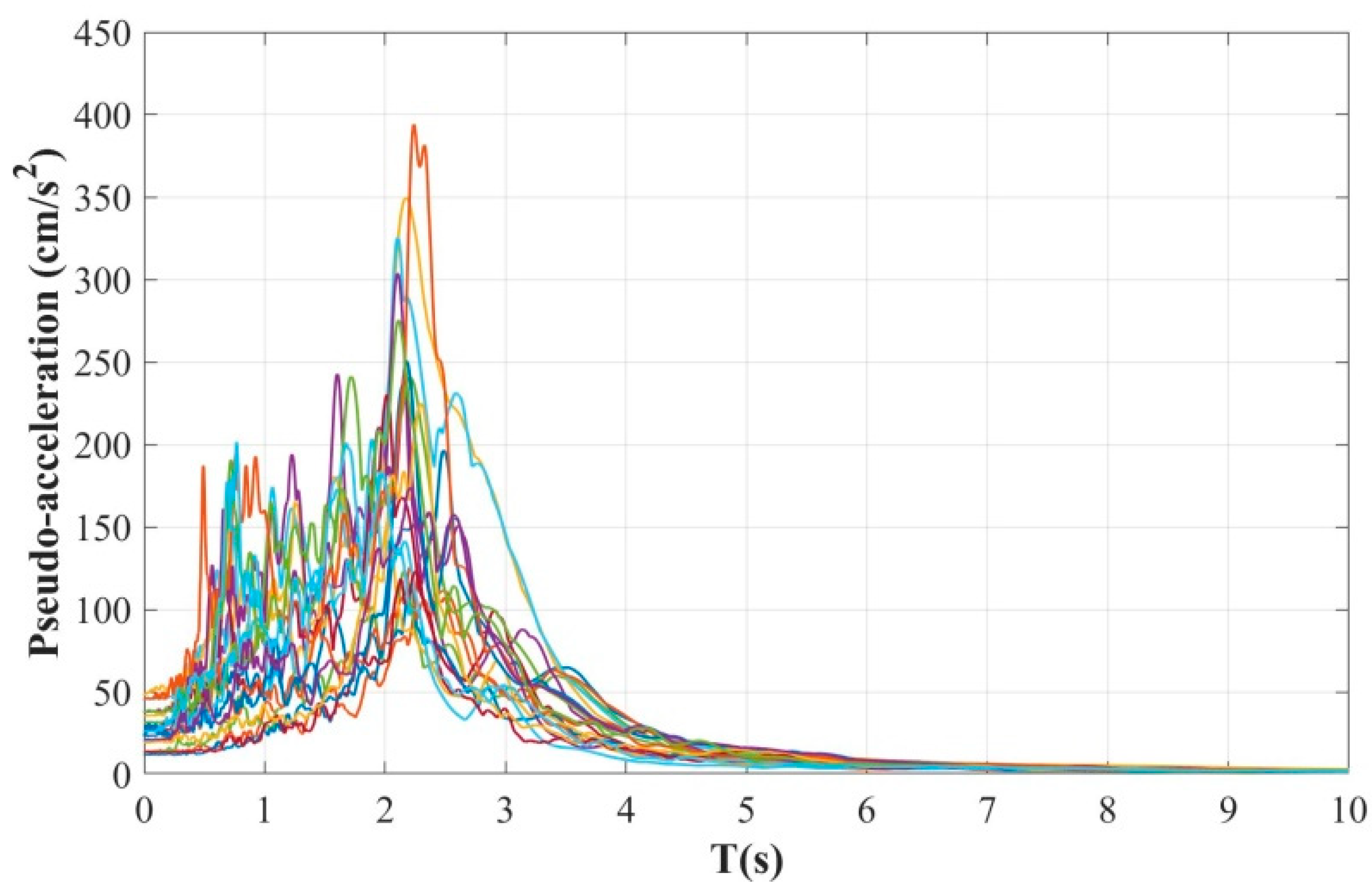
2.3. Earthquake Ground Motions

The dynamic response of a structure is dependent on several factors, including the frequency content of the seismic excitation time history and the dynamic properties of the structure. An estimation of the seismic response of a structure in an earthquake may not reflect its behavior properly, due to the different content of frequencies that earthquakes can present, even if they occur in the same place. To study the structural behavior of the selected building models carefully, the models were subjected to a set of 20 ground motion records, as illustrated in Table 2. It is important to note that these ground motions were recorded at stations located on soft soil in Mexico City.
The recorded earthquakes used here have characteristics in common, such as very similar magnitudes, durations, frequency contents, accelerations, and peak ground velocities. Figure 6 shows the response spectra in terms of pseudo-acceleration for all the selected ground motion records.
In order to directly compare the responses of the different structural models, they were subjected to the same ground motion recorded at the SCT station during an earthquake that occurred in Mexico City in 1985, which had a magnitude of 8.1. This acceleration record was used because that earthquake was one of the most destructive seismic events in the history of Mexico City.

3. Seismic Analysis and Numerical Results

The structural performance of the different steel buildings subjected to seismic loads was evaluated by applying incremental dynamic analysis (IDA), a type of analysis extensively described in Vamvatsikos and Cornell [50]. To ensure that the structural models experienced significant behavior in their inelastic range, they were excited by a set of 20 ground motions, scaled at multiple levels of seismic intensity in terms of the spectral acceleration at the first mode of vibration. The scaling of the seismic records for different intensity levels allowed each structure to present a behavior that ranges from the elastic to inelastic range or to exhibit a certain behavior associated with a level of performance, all in search of specific objectives.
The intensity measure commonly used in earthquake engineering is spectral pseudo-acceleration, which corresponds to the fundamental period of vibration of the structure, expressed as Sa(T1). It is convenient to use an intensity measure of the scalar type, because it allows for a clear understanding of the destructive potential of a seismic motion [51,52,53]. To perform an IDA, the acceleration history of each seismic record was scaled with the objective of reaching intensity levels from Sa(T1) = 0.1 g to Sa(T1) = 2.0 g, at increments of Sa(T1) = 0.1 g. In this study, the seismic response parameters of interest for each time history, scaled to a specific intensity, correspond to the peak interstory drifts and hysteretic behavior of the links.
The analytical results obtained from the nonlinear dynamic analysis have been divided into three parts. In the first part, the IDAs used to evaluate the peak interstory drifts are presented, in which each earthquake ground motion was scaled to different target intensity levels. It is important to note that the scale factors employed here were not identical for each acceleration history at a given level of Sa(T1), due to variability in spectral ordinates (see Figure 6) and the different vibration periods of the structural models (see Table 1). In the second part, a direct comparison of the vertical profiles, in terms of the peak interstory drifts of the structural models with different configuration of EBFs, is presented. Here, a single earthquake ground motion was used, which was scaled for a certain target intensity level. In addition, the hysteretic behavior of the links corresponding to the critical story, that is, where the structural damage was most concentrated, is shown. Finally, in the third part, the incremental dynamic analysis used to evaluate peak residual interstory drift is presented, in which each structural model was left in free vibration for a period of 40 s after the seismic excitation finished.

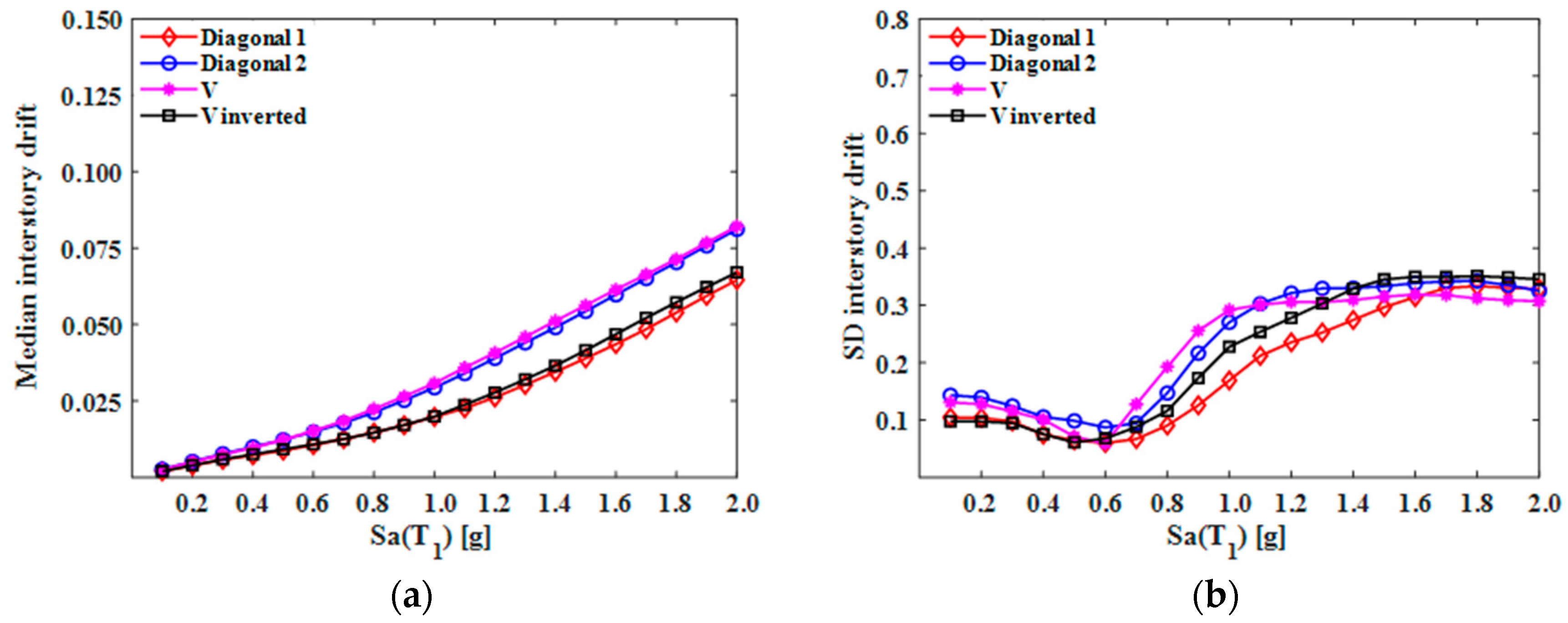
3.1. Peak Interstory Drifts

IDAs are shown in Figure 7, Figure 8 and Figure 9 for the steel buildings of five, 10, and 15 levels, structured with different bracing configurations. In these figures, it is evident that different structural models with the same number of stories exhibited similar seismic performance in terms of peak interstory drift. The evaluated seismic demand increased as the level of intensity increased. As is evident in Figure 7, the behavior of the structural response had a linear increasing trend for the first levels of intensities; beyond the lower levels, a greater dispersion in the values of the interstory drifts can be observed, increasing considerably as the level of intensity increased. This can be explained by the behavior of the link. Because it is the weak element within the structural system, the link assumes the inelastic response; therefore, when the intensity of the ground motion increases, it will enter a state beyond yield and hysteresis will take place, producing loss of strength and lateral stiffness in the system and, consequently, high lateral displacement.
For all the cases depicted in the figures that present the IDAs (models of five, 10, and 15 levels), the efficiency, in terms of reducing peak drifts for each type of configuration of the EBF, is not clearly observed because the models with the same number of stories exhibited almost the same level of response; thus, this way of exposing the results of the peak interstory drifts is not appropriate if the purpose is to identify the efficiency of each structural system. For this reason, the median values of the responses were determined at different intensity levels. In addition, standard deviations (SDs) were calculated in order to observe the degree of variability of the values (see Figure 10b, Figure 11b and Figure 12b). It is evident that, as the intensity increased in terms of spectral acceleration, the SD for all the steel buildings under consideration also tended to increase.
Analyzing the median values of the peak interstory drifts for the five- and 10-level models, it can be observed that the frame configurations named Diagonal_1 and V_Inverted presented a lower level of structural response, maintaining a very similar behavior at all intensity levels; in contrast, the configuration named V exhibited a higher level of seismic response. In the case of the 15-level models, identifying which of them presented better behavior is complicated, since they demonstrated similar performance across different intensity values. In general, the configurations of EBFs that showed more efficiency in reducing seismic response, in terms of drift, were the Diagonal_1 and V_Inverted. These configurations are the most commonly used in the practice of earthquake engineering.

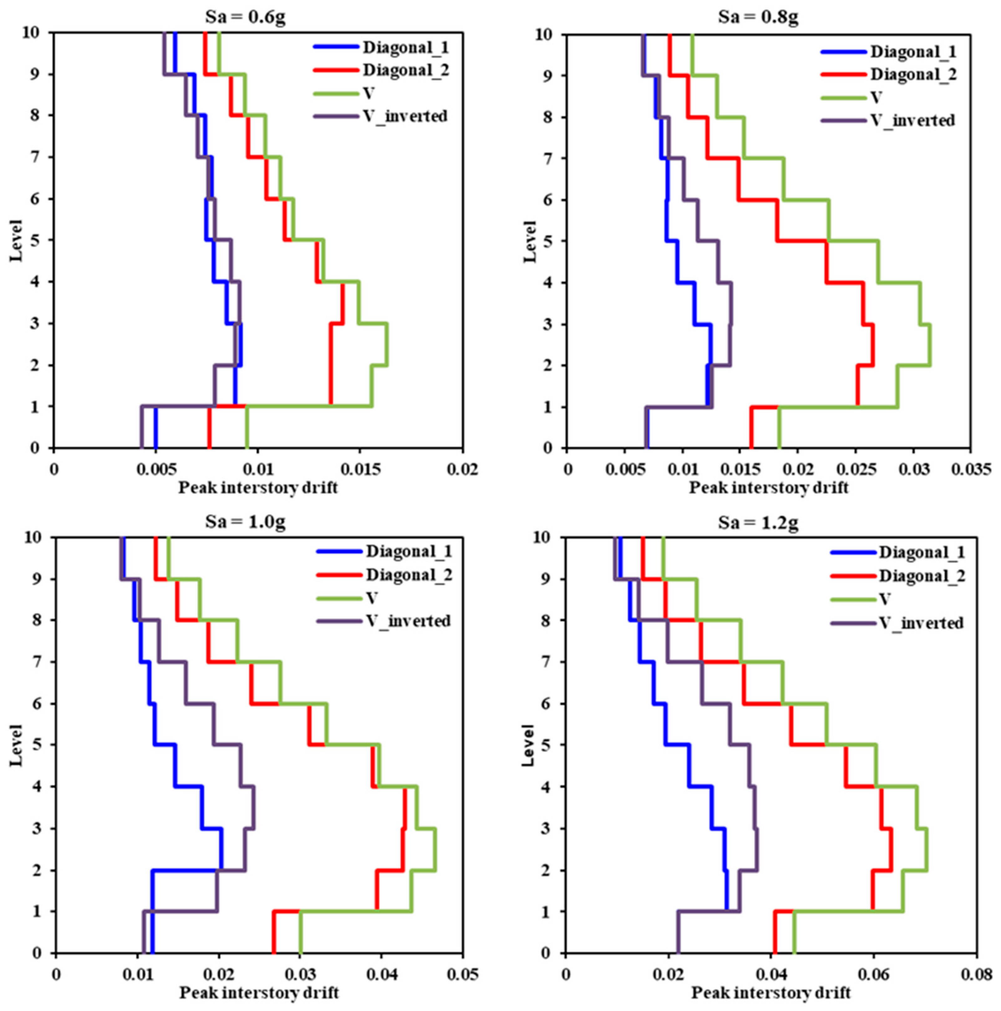
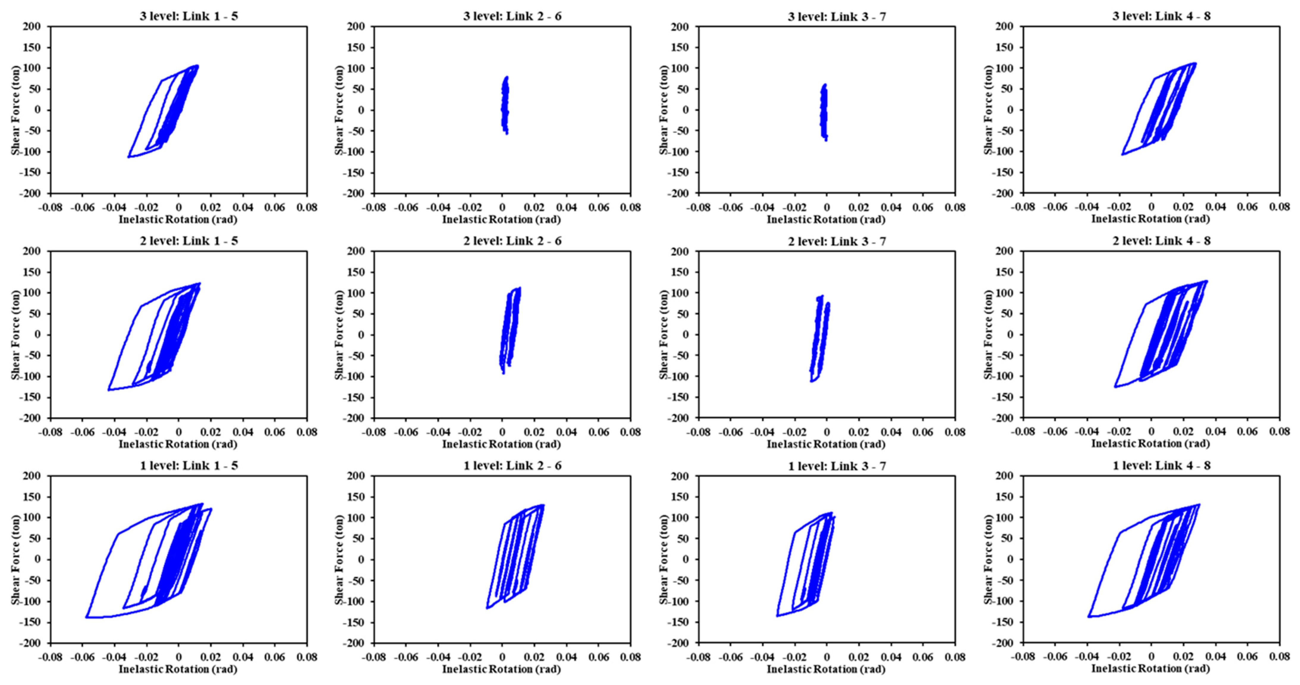
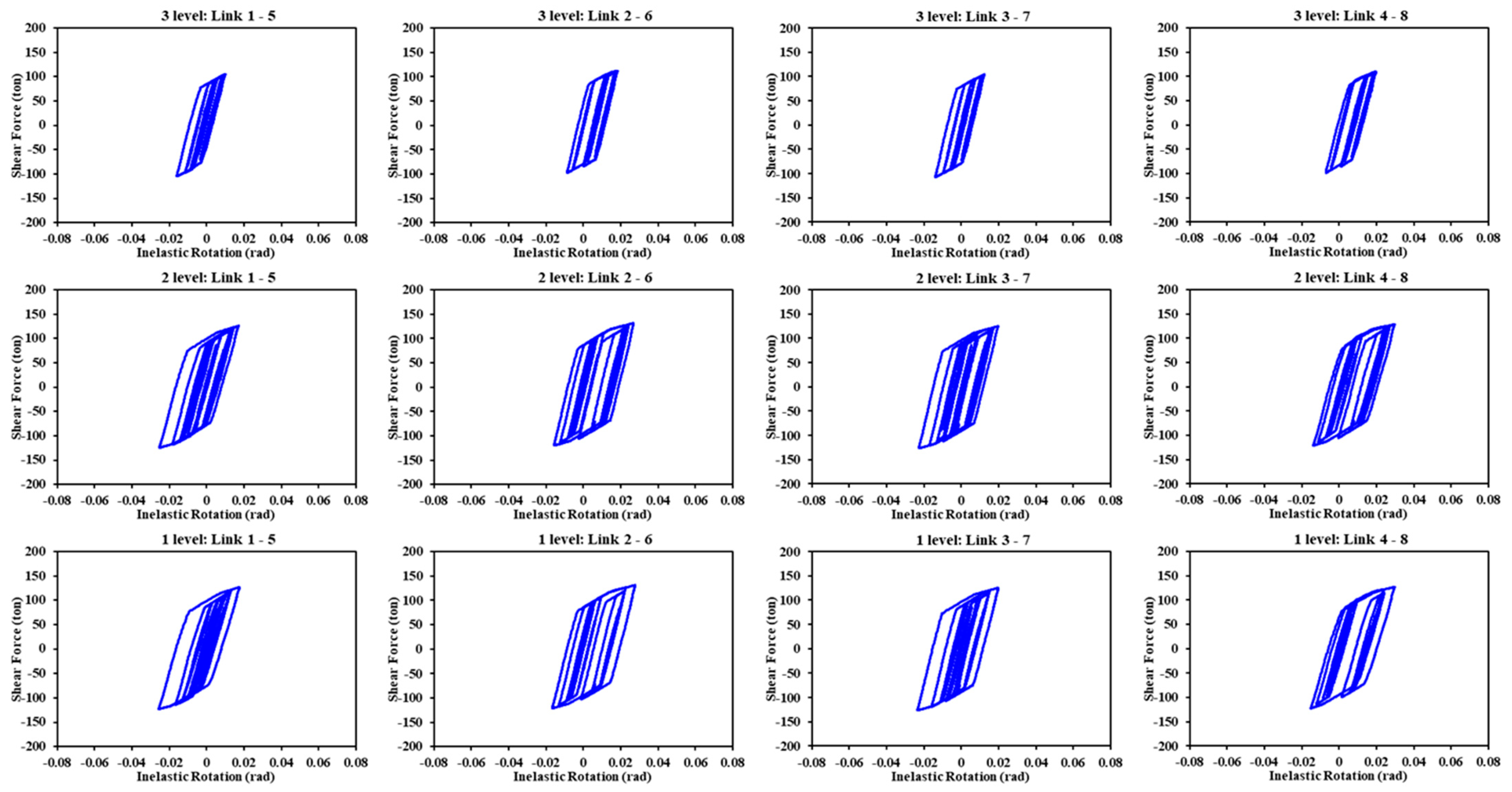
3.2. Comparison of Peak Interstory Drift Profiles and the Behavior of the Link

As mentioned earlier, in order to perform a direct comparison between the seismic responses of the different structural models, in terms of peak interstory drift and the hysteretic behavior of the links, they were subjected to the same single ground motion recorded during the 1985 Mexico earthquake and scaled at different target intensity levels, which allowed us to make meaningful comparisons. Figure 13, Figure 14 and Figure 15 show the vertical profiles of the peak interstory drifts corresponding to intensity levels 0.6 g, 0.8 g, 1.0 g, and 1.2 g for the frame configurations of the models of five, 10, and 15 floors, respectively.
Comparison of the drift profiles of the different models enabled us to observe that, in most cases, across intensity levels, the buildings structured with the Diagonal_1 bracing configuration developed the lowest seismic response levels; conversely, the models called “V” exhibited the greatest interstory drifts. Evidently, the seismic response depends on the period of the structure. If, however, the behavior of the Diagonal_1 and V_Inverted models is analyzed in detail, it is evident that their responses did not depend directly or only on this dynamic property, given that, practically speaking, they underwent the same period of vibration.
It is therefore necessary to study the behavior of the elements that govern the performance of this type of structural system (EBF); in this case, that element is the link.
In order to understand the peak interstory drift levels that each structural model developed, the behavior of the links was analyzed. The hysteretic curves of all the links comprising the different models were drawn; however, only those graphs of the elements that developed the greatest inelastic rotation are presented here. Typically, these correspond to the story where the most structural damage was concentrated; in the other words, the story that presented the peak drift (see Figure 16, Figures 19 and 20). It is important to note that, according to the modeling and idealization of the structures in the OpenSees program, the Diagonal_1 and V_Inverted models have four links in each story, while the Diagonal_2 and V models contain eight each.
The hysteresis curves presented correspond to those analyses where the seismic load was scaled to target intensity level Sa = 1.0 g; in these figures, the X-axis contains the inelastic rotation and the Y-axis, the shear force.
Figure 16 illustrates the hysteretic curves of the links in the five-level models. Here, it is evident that the links corresponding to the Diagonal_1 and V_Inverted models developed very similar levels of inelastic rotation, producing comparable interstory drifts, which can be verified by looking at the vertical profile of the peak interstory drifts (see Figure 13, Sa = 1.0 g). On the other hand, the links in the V and Diagonal_2 models exhibited the lowest and highest levels of inelastic rotation, respectively. Despite this, the V model that experienced the greatest lateral displacement presented the least rotation in its links, which can be explained by the number of links it had per floor compared to the Diagonal_1 and V_Inverted models. Here, the difference in structural performance is associated with the fact that all the links in the same story in the V model developed similar values of inelastic rotation and a stable hysteretic behavior; these are characteristics that were not manifested in the links in the Diagonal_2 model.
In order to clearly identify the structural behavior of the Diagonal_2 and V models, the hysteretic curves of the links corresponding to the floors where at least one of these elements entered an inelastic range are presented. In both models, this occurred in the first three levels; thereafter, all links remained within their elastic range.
Figure 17 and Figure 18 show the hysteretic curves of the links in the Diagonal_2 and V models, respectively. Analyzing Figure 17, it can be observed that, as mentioned above, the links behaved differently even when they belonged to the same floor. In addition, the links located at the ends of the frames (links 1–5 and 4–8) developed a greater structural response and the hysteretic curves were stable as the height of each model increased. Conversely, the rotation of the links located inside the frames (links 2–6 and 3–7) was less, and their incursion into the inelastic range, from the second story, was almost null. This behavior was not exhibited by the links in the V model (see Figure 18); on the contrary, these exhibited a very similar behavior and the hysteretic curves were stable in each floor. Accordingly, it is evident that the V model developed the greatest drift.
Figure 19 shows the hysteretic curves of the links in the 10-level models. This figure illustrates that the link belonging to the Diagonal_1 model experienced the least inelastic rotation; consequently, this model presented the lowest levels of lateral displacement. In the V and V_Inverted models, the hysteretic curves of their elements were similar, reaching an almost identical level of seismic response. The magnitude of link rotation in the V_Inverted model was slightly higher, but the peak interstory drifts were lower than those corresponding to the V model, given that the V model contained twice the number of the links per story; thus, there was a greater loss of lateral strength when yield occurred in these elements. In particular, the seismic performance of the 10-level models was similar to that previously presented and described in analyses of the responses of the 5-level models. In both sets of models, the links exhibited a different behavior in each floor and the differences became more evident as the height of the model increased. Finally, the hysteretic curves of the links in the 15-level models are analyzed in Figure 20. It is evident that, in all cases, the hysteretic behavior cycles were quite similar across the five-, 10-, and 15- level models. In general, based on the numerical results, it can be observed that the Diagonal_1 bracing configuration demonstrated a better performance, in terms of controlling peak interstory drift, under the seismic excitation selected for the present study.
Figure 19. Hysteretic curves of the links corresponding to the 10-level model: (a) Diagonal_1; (b) Diagonal_2; (c) V; and (d) V_Inverted.
Buildings 14 00118 g019
Figure 20. Hysteretic curves of the links corresponding to the 15-level model: (a) Diagonal_1; (b) Diagonal_2; (c) V; and (d) V_Inverted.
Buildings 14 00118 g020

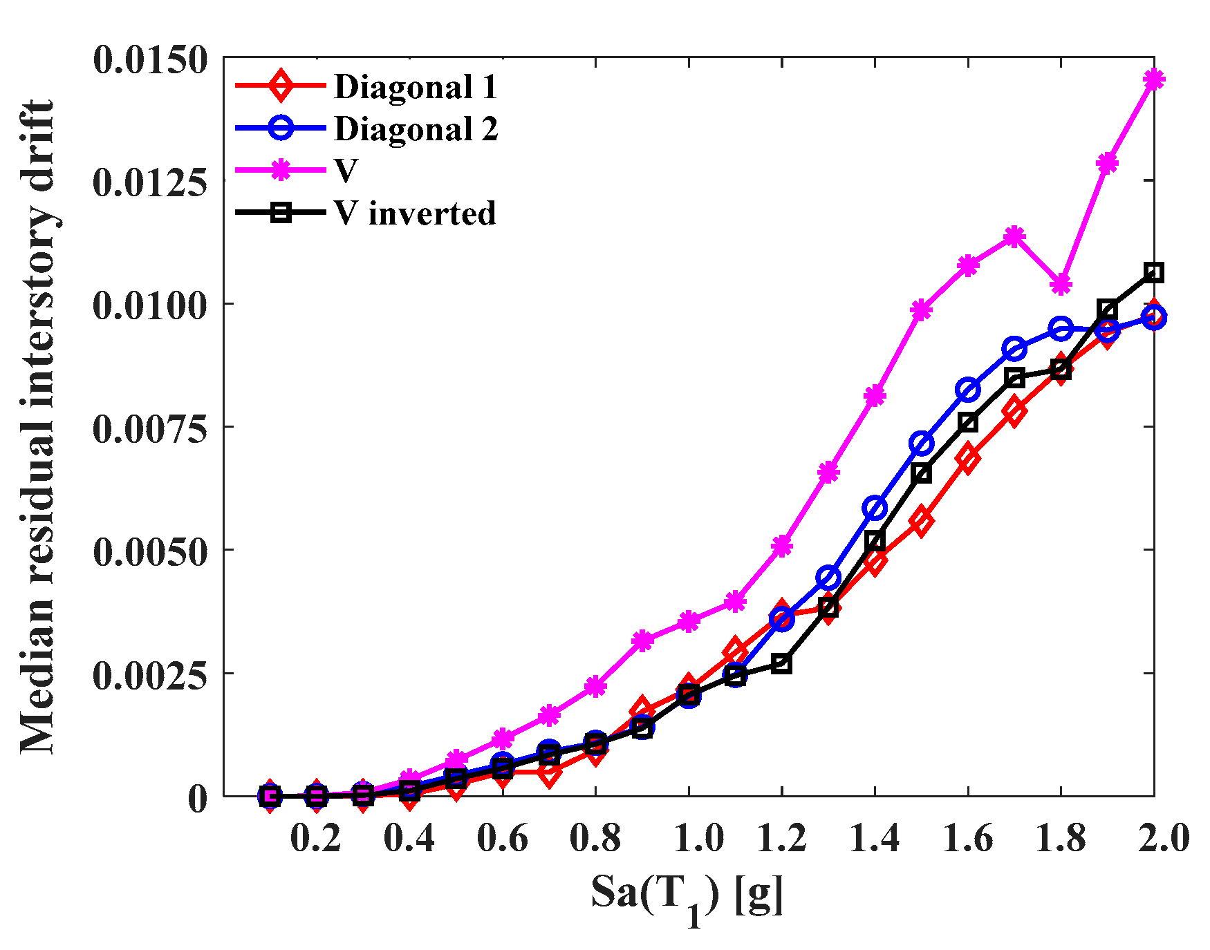
3.3. Peak Residual Interstory Drifts

Residual drift is a response parameter that, like peak drifts, must be taken into account in structural design and in the evaluation of damage to existing structures. Estimating residual drift plays an important role in determining the technical and economic feasibility of repairing or demolishing a structure that has been damaged by severe earthquake ground motions.
In order to determine this parameter, the structural analyses were configured so that, once each seismic record was finished, the models were left in free vibration for 40 s; this is enough time for the effect of the earthquake to be absorbed by the structural model. The drift exhibited in this 40 s period was considered residual in this study.
Figure 21, Figure 22 and Figure 23 present the incremental dynamic analysis of the five-, 10-, and 15-story buildings for the different frame configurations, respectively. These figures show that the response levels of the models with the same number of floors were comparable; in most cases, response levels increased as the intensity of the excitation increased. This type of behavior was also observed in the analysis of peak interstory drifts.
In Figure 21, it is possible to identify that, for different levels of intensity, the discrete data (peak residual interstory drifts) for model V have a greater magnitude and dispersion. The responses of the structural models presented a linear trend, increasing in the first eight or 10 intensity levels; and, thereafter, an important dispersion of data was shown as the seismic intensity increased. It is important to note that the different frame types reflected a decrease in residual demand when some ground motion records were scaled to 1.9 g and 2.0 g; moreover, the results of the structural response of the 10-level models (see Figure 22) show that the Diagonal_1 and V_Inverted models developed the lowest levels of response, with the exception of one particular seismic event. On the other hand, the Diagonal_2 model exhibited uniform discrete data dispersion, where there was an increasing linear trend as the intensity increased. The 10-level V model, as was the case in the 5-level V model, exhibited the highest values for certain seismic intensities. In these models, much like the 5-level models, the residual drift values for a certain level of intensity may be less than those of the previous level, which means that there does not necessarily have to be an increase in the magnitude of this parameter as the intensity of the seismic excitation increases.
It is notable that, regarding the 15-level models, the peak residual interstory drifts behaved in a similar way across different intensities (see Figure 23). A clear trend, in terms of the response between one type of frame and another, cannot be identified; however, it is evident that, for high intensity levels, the V_Inverted model experienced the highest drift values. Additionally, as previously observed in the five- and 10-level models, the residual drifts can decrease as the seismic intensity increases, making it difficult to predict this response parameter.
Identifying the best frame configuration to assist in limiting residual interstory drifts becomes complicated if we analyze peak values alone, such as those presented in the previous figures. In order to study this response parameter in more detail, Figure 24, Figure 25 and Figure 26 present the medians of the peak residual interstory drifts for the different levels of intensity.
In Figure 24, which illustrates the median interstory drifts in the 5-level models, it is clear that the V model was the least effective in reducing this type of structural response; the other frame configurations performed similarly at the first 10 intensities, that is, up to 1.0 g. Beyond 1.0 g, the behavior became variable, which makes it difficult to define which model is better than another; however, it can be recognized that, in most intensities, the Diagonal_1 model exhibited drift values equal to or lower than the other models. On the other hand, in Figure 25, it is possible to identify that the 10-level models of the Diagonal_1 and V_Inverted types maintained a structural response in lower magnitudes. Both models behaved in a similar way up to an intensity of 1.5 g; beyond 1.5 g, the response of the V_Inverted model tended to be higher. The Diagonal_2 and V configurations performed in a similar way up to 1.3 g. Beyond that intensity, their behavior was variable; in some cases, the residual drift of a specific frame configuration was higher and, in others, lower. Finally, in Figure 26, the medians of the responses of the 15-level models are analyzed. A similarity in terms of the drift can be observed across the different types of frames up to an intensity of 1.0 g. Beyond 1.0 g, an alternative behavior was presented. In the ranges from 1.0 g to 1.4 g, the Diagonal_1 and V_Inverted models exhibited interstory drift levels equal to or less than the Diagonal_2 and V models; however, for intensities greater than 1.5 g, the response in the Diagonal_1 and V_Inverted models, compared to the Diagonal_2 and V models, was greater.

4. Conclusions

Configurations of different types of eccentrically braced frames (EBFs) were subjected to a set of earthquake ground motions recorded on the soft soil of Mexico City and scaled at different target intensity levels in terms of the spectral acceleration at the first mode of vibration. The results obtained from the nonlinear dynamic analysis, in terms of peak interstory drifts and peak residual interstory drifts, suggest that the brace configurations with the best structural performance are Diagonal_1 and V_Inverted. Their median drifts present lower values and a very similar behavior. Analyzing the structural models under a particular ground motion record, it can be observed that peak interstory drift demands are highly dependent on the behavior of the link element, demonstrating that, in this type of structural system (EBF), the link is a fundamental element that controls lateral stiffness and energy dissipation. In addition, a non-uniform distribution of energy dissipation along the height was observed due to the hysteretic behavior of the links. In the lower stories, the links exhibit an inelastic behavior; in the upper stories, they remain in the elastic range. This non-uniform behavior prevents the system from taking full advantage of its energy dissipation capacity.

Author Contributions

Conceptualization, E.B.; methodology, E.B. and J.A.; software, J.A. and E.B.; validation, E.B., J.B., A.R.-S., J.R.-G., S.E.R. and I.I.; formal analysis, J.A. and J.B.; investigation, J.A., E.B. and J.R.-G.; resources, E.B.; data curation, J.B.; writing—original draft preparation, J.A., E.B. and J.B.; writing—review and editing, E.B., A.R.-S., S.E.R., J.R.-G. and I.I.; visualization, J.A. and J.B.; supervision, E.B. and J.B.; project administration, E.B. and J.B.; funding acquisition, E.B. and J.B. All authors have read and agreed to the published version of the manuscript.

Funding

This research was developed thanks to economic support provided by the Consejo Nacional de Humanidades, Ciencias y Tecnologías (CONAHCYT) for the scholarship of the student and under Grant Ciencia de Frontera CF-2023-G-1636 and Ciencia Básica 287103. Finally, the support received from the Autonomous University of Sinaloa within the PROFAPI project is appreciated.

Data Availability Statement

The data are available under reasonable request to the corresponding authors. The data are not publicly available due to privacy.

Conflicts of Interest

The authors declare no conflict of interest. The funders had no role in the design of the study; in the collection, analyses, or interpretation of data; in the writing of the manuscript; or in the decision to publish the results.

Appendix A

Table A1. Summary of the cross sections of the structural elements of the five-level steel buildings.
Structural Model5S4B_V_Inverted5S4B_V5S4B_Diagonal_15S4B_Diagonal_2
Internal columns
Story 1W21X93W21X93W21X93W21X93
Story 2W21X93W21X93W21X93W21X93
Story 3W21X73W21X73W21X83W21X83
Story 4W21X73W21X73W21X83W21X83
Story 5W21X62W21X62W21X62W21X62
External columns
Story 1W21X73W21X73W21X83W21X83
Story 2W21X73W21X73W21X83W21X83
Story 3W21X62W21X62W21X62W21X62
Story 4W21X62W21X62W21X62W21X62
Story 5W21X57W21X57W21X57W21X57
Internal beams
Story 1W21X50W21X44W21X50W21X44
Story 2W21X50W21X44W21X50W21X44
Story 3W18X46W21X44W21X50W21X44
Story 4W18X46W21X44W21X50W21X44
Story 5W18X46W18X40W18X46W18X40
External beams
Story 1W18X55W18X55W18X60W18X55
Story 2W18X55W18X55W18X60W18X55
Story 3W18X50W18X50W18X55W18X50
Story 4W18X50W18X50W18X55W18X50
Story 5W16X45W16X45W16X45W16X45
Braces
Story 1HSS6X6X3/8HSS6X6X5/16HSS8X8X5/8HSS8X8X3/8
Story 2HSS6X6X3/8HSS6X6X5/16HSS8X8X5/8HSS8X8X3/8
Story 3HSS6X6X5/16HSS6X6X5/16HSS8X8X5/8HSS8X8X3/8
Story 4HSS6X6X5/16HSS6X6X5/16HSS8X8X1/2HSS8X8X3/8
Story 5HSS6X6X5/16HSS6X6X5/16HSS8X8X3/8HSS8X8X3/8
Table A2. Summary of the cross sections of the structural elements of the 10-level steel buildings.
Structural Model10S4B_V_Inverted10S4B_V10S4B_Diagonal_110S4B_Diagonal_2
Internal columns
Story 1W36X256W36X194W36X262W36X210
Story 2W36X256W36X194W36X262W36X210
Story 3W36X256W36X194W36X262W36X210
Story 4W36X231W36X182W36X247W36X194
Story 5W36X231W36X182W36X247W36X194
Story 6W36X231W36X182W36X247W36X194
Story 7W36X194W36X170W36X231W36X182
Story 8W36X194W36X170W36X231W36X182
Story 9W36X160W36X160W36X182W36X160
Story 10W36X160W36X160W36X182W36X160
External columns
Story 1W36X231W36X182W36X247W36X194
Story 2W36X231W36X182W36X247W36X194
Story 3W36X231W36X182W36X247W36X194
Story 4W36X194W36X170W36X231W36X182
Story 5W36X194W36X170W36X231W36X182
Story 6W36X194W36X170W36X231W36X182
Story 7W36X160W36X160W36X182W36X160
Story 8W36X160W36X160W36X182W36X160
Story 9W36X150W36X150W36X150W36X150
Story 10W36X150W36X150W36X150W36X150
Internal beams
Story 1W24X76W24X76W24X84W24X76
Story 2W24X76W24X76W24X84W24X76
Story 3W24X68W24X68W24X84W24X76
Story 4W24X68W24X68W24X76W24X62
Story 5W24X62W24X62W24X76W24X62
Story 6W24X62W24X62W24X76W24X62
Story 7W21X50W21X50W24X62W21X55
Story 8W21X50W21X50W24X62W21X55
Story 9W18X46W18X40W18X46W18X40
Story 10W18X46W18X40W18X46W18X40
External beams
Story 1W21X93W21X83W21X101W21X83
Story 2W21X93W21X83W21X101W21X83
Story 3W21X83W21X73W21X101W21X83
Story 4W21X83W21X73W21X93W21X73
Story 5W21X73W21X68W21X93W21X73
Story 6W21X73W21X68W21X93W21X73
Story 7W18X71W18X60W21X73W21X68
Story 8W18X71W18X60W21X73W21X68
Story 9W16X45W16X45W18X55W18X55
Story 10W16X45W16X45W18X55W18X55
Braces
Story 1HSS10X10X5/8HSS10X10X5/8HSS12X12X5/8HSS10X10X5/8
Story 2HSS10X10X5/8HSS10X10X5/8HSS12X12X5/8HSS10X10X5/8
Story 3HSS10X10X5/8HSS10X10X5/8HSS12X12X5/8HSS10X10X5/8
Story 4HSS8X8X5/8HSS10X10X1/2HSS10X10X5/8HSS10X10X1/2
Story 5HSS8X8X5/8HSS10X10X1/2HSS10X10X5/8HSS10X10X1/2
Story 6HSS8X8X5/8HSS10X10X1/2HSS10X10X5/8HSS10X10X1/2
Story 7HSS8X8X1/2HSS8X8X1/2HSS10X10X1/2HSS10X10X3/8
Story 8HSS8X8X1/2HSS8X8X1/2HSS10X10X1/2HSS10X10X3/8
Story 9HSS8X8X3/8HSS8X8X3/8HSS8X8X1/2HSS8X8X3/8
Story 10HSS8X8X3/8HSS8X8X3/8HSS8X8X1/2HSS8X8X3/8
Table A3. Summary of the cross sections of the structural elements of the 15-level steel buildings.
Structural Model15S4B_V_Inverted15S4B_V15S4B_Diagonal_115S4B_Diagonal_2
Internal columns
Story 1W36X441W36X395W36X487W36X395
Story 2W36X441W36X395W36X487W36X395
Story 3W36X441W36X395W36X487W36X395
Story 4W36X395W36X361W36X441W36X361
Story 5W36X395W36X361W36X441W36X361
Story 6W36X395W36X361W36X441W36X361
Story 7W36X330W36X330W36X395W36X330
Story 8W36X330W36X330W36X395W36X330
Story 9W36X330W36X330W36X395W36X330
Story 10W36X302W36X302W36X361W36X282
Story 11W36X302W36X302W36X361W36X282
Story 12W36X282W36X282W36X302W36X262
Story 13W36X282W36X282W36X302W36X262
Story 14W36X262W36X247W36X247W36X232
Story 15W36X262W36X247W36X247W36X232
External columns
Story 1W36X395W36X361W36X441W36X361
Story 2W36X395W36X361W36X441W36X361
Story 3W36X395W36X361W36X441W36X361
Story 4W36X330W36X330W36X395W36X330
Story 5W36X330W36X330W36X395W36X330
Story 6W36X330W36X330W36X395W36X330
Story 7W36X302W36X302W36X361W36X282
Story 8W36X302W36X302W36X361W36X282
Story 9W36X302W36X302W36X361W36X282
Story 10W36X282W36X282W36X302W36X262
Story 11W36X282W36X282W36X302W36X262
Story 12W36X262W36X247W36X247W36X232
Story 13W36X262W36X247W36X247W36X232
Story 14W36X247W36X232W36X194W36X194
Story 15W36X247W36X232W36X194W36X194
Internal beams
Story 1W27X129W27X129W30X132W27X129
Story 2W27X129W27X129W30X132W27X129
Story 3W27X129W27X129W30X132W27X129
Story 4W27X114W27X114W30X124W27X114
Story 5W27X114W27X114W30X124W27X114
Story 6W27X114W27X114W30X124W27X114
Story 7W27X102W27X94W30X108W27X102
Story 8W27X102W27X94W30X108W27X102
Story 9W27X102W27X94W30X108W27X102
Story 10W27X94W27X84W30X99W27X84
Story 11W27X94W27X84W30X99W27X84
Story 12W27X84W24X68W27X84W24X68
Story 13W27X84W24X68W27X84W24X68
Story 14W24X68W21X50W24X55W21X50
Story 15W24X68W21X50W24X55W21X50
External beams
Story 1W24X146W24X131W24X162W24X146
Story 2W24X146W24X131W24X162W24X146
Story 3W24X146W24X131W24X162W24X146
Story 4W24X131W24X117W24X146W24X131
Story 5W24X131W24X117W24X146W24X131
Story 6W24X131W24X117W24X146W24X131
Story 7W24X117W24X103W24X131W24X117
Story 8W24X117W24X103W24X131W24X117
Story 9W24X117W24X103W24X131W24X117
Story 10W24X103W24X94W24X117W24X94
Story 11W24X103W24X94W24X117W24X94
Story 12W24X94W24X84W24X94W24X84
Story 13W24X94W24X84W24X94W24X84
Story 14W24X84W24X62W21X62W21X62
Story 15W24X84W24X62W21X62W21X62
Braces
Story 1HSS16X16X5/8HSS14X14X5/8HSS16X16X5/8HSS14X14X5/8
Story 2HSS16X16X5/8HSS14X14X5/8HSS16X16X5/8HSS14X14X5/8
Story 3HSS16X16X5/8HSS14X14X5/8HSS16X16X5/8HSS14X14X5/8
Story 4HSS14X14X5/8HSS12X12X5/8HSS16X16X5/8HSS12X12X5/8
Story 5HSS14X14X5/8HSS12X12X5/8HSS16X16X5/8HSS12X12X5/8
Story 6HSS14X14X5/8HSS12X12X5/8HSS16X16X5/8HSS12X12X5/8
Story 7HSS14X14X5/8HSS12X12X5/8HSS14X14X5/8HSS12X12X5/8
Story 8HSS14X14X5/8HSS12X12X5/8HSS14X14X5/8HSS12X12X5/8
Story 9HSS14X14X5/8HSS12X12X5/8HSS14X14X5/8HSS12X12X5/8
Story 10HSS12X12X5/8HSS10X10X1/2HSS14X14X5/8HSS10X10X1/2
Story 11HSS12X12X5/8HSS10X10X1/2HSS12X12X1/2HSS10X10X1/2
Story 12HSS10X10X1/2HSS8X8X1/2HSS12X12X1/2HSS8X8X1/2
Story 13HSS10X10X1/2HSS8X8X1/2HSS12X12X1/2HSS8X8X1/2
Story 14HSS8X8X3/8HSS8X8X3/8HSS10X10X1/2HSS8X8X3/8
Story 15HSS8X8X3/8HSS8X8X3/8HSS10X10X1/2HSS8X8X3/8

References

  1. Hjelmstad, K.D.; Popov, E.P. Seismic Behavior of Active Beams Links in Eccentrically Braced Frames; Earthquake Engineering Research Center, University of California: Berkeley, CA, USA, 1983. [Google Scholar]
  2. Malley, J.O.; Popov, E.P. Design Considerations for Shear Links in Eccentrically Braced Frames; Earthquake Engineering Research Center, University of California: Berkeley, CA, USA, 1983. [Google Scholar]
  3. Kasai, K.; Popov, E.P. A Study of Seismically Resistant Eccentrically Braced Steel Frame Systems; Earthquake Engineering Research Center, University of California: Berkeley, CA, USA, 1986. [Google Scholar]
  4. Prinz, G.S. Using Buckling-Restrained Braces in Eccentric Configurations. Ph.D. Thesis, Brigham Young University, Provo, UT, USA, 2010. [Google Scholar]
  5. Yiğitsoy, G. A numerical Study on Beam Stability in Eccentrically Braced Frames. Master´s Thesis, Middle East Technical University, Ankara, Turkey, 2010. [Google Scholar]
  6. Spurr, H.V. Wind Bracing: The Importance of Rigidity in High Towers; McGraw-Hill: New York, NY, USA, 1930. [Google Scholar]
  7. Fujimoto, M.; Aoyagi, T.; Ukai, K.; Wada, A.; Saito, K. Structural characteristics of eccentric K-braced frames. Trans. Arch.-Tectural Inst. Jpn. 1972, 195, 39–49. [Google Scholar] [CrossRef] [PubMed]
  8. Tanabashi, R.; Kaneta, K.; Ishida, T. On the rigidity and ductility of Steel bracing assemblage. In Proceedings of the 5th World Conference on Earthquake Engineering, Rome, Italy, 25–29 June 1973; IAEE: Rome, Italy, 1974; pp. 834–840. [Google Scholar]
  9. Roeder, C.W.; Popov, E.P. Inelastic Behavior of Eccentrically Braced Steel Frames under Cyclic Loadings; Earthquake Engineering Research Center, University of California: Berkeley, CA, USA, 1977. [Google Scholar]
  10. Roeder, C.W.; Popov, E.P. Cyclic shear yielding of wide-flange beams. J. Eng. Mech. Div. 1978, 104, 763–780. [Google Scholar] [CrossRef]
  11. Roeder, C.W.; Popov, E.P. Eccentrically braced steel frames for earthquakes. J. Struct. Div. 1978, 104, 391–412. [Google Scholar] [CrossRef]
  12. Engelhardt, M.D.; Kasai, K.; Popov, E.P. Advances in design of eccentrically braced frames. Earthq. Spectra 1987, 3, 43–55. [Google Scholar] [CrossRef]
  13. Ricles, J.M.; Popov, E.P. Experiments on Eccentrically Braced Frames with Composite Floors; Earthquake Engineering Research Center, University of California: Berkeley, CA, USA, 1987. [Google Scholar]
  14. Engelhardt, M.D.; Popov, E.P. Seismic eccentrically braced frames. J. Constr. Steel Res. 1988, 10, 321–354. [Google Scholar] [CrossRef]
  15. Engelhardt, M.D.; Popov, E.P. On design of eccentrically braced frames. Earthq. Spectra 1989, 5, 495–511. [Google Scholar] [CrossRef]
  16. Bosco, M.; Rossi, P.P. Seismic behavior of eccentrically braced frames. Eng. Struct. 2009, 31, 664–674. [Google Scholar] [CrossRef]
  17. Azad, S.K.; Topkaya, C. A review of research on steel eccentrically braced frames. J. Constr. Steel Res. 2017, 128, 53–73. [Google Scholar] [CrossRef]
  18. Manheim, D.N. On the Design of Eccentrically Braced Frames. Ph.D. Thesis, Department of Civil and Environmental Engineering, University of California, Berkeley, CA, USA, 1982. [Google Scholar]
  19. Whittaker, A.S.; Uang, C.M.; Bertero, V.V. Earthquake Simulation Tests and Associated Studies of a 0.3-Scale Model of a Six-Story Eccentrically Braced Steel Structure; Earthquake Engineering Research Center, University of California: Berkeley, CA, USA, 1987. [Google Scholar]
  20. Roeder, C.W.; Foutch, D.A.; Goel, S.C. Seismic Testing of Full-Scale Steel Building—Part II. J. Struct. Eng. 1987, 113, 2130–2145. [Google Scholar] [CrossRef]
  21. Ricles, J.M.; Popov, E.P. Dynamic Analysis of Seismically Resistant Eccentrically Braced Frames; Earthquake Engineering Research Center, University of California: Berkeley, CA, USA, 1987. [Google Scholar]
  22. Whittaker, A.S.; Uang, C.M.; Bertero, V.V. Seismic Testing of Eccentrically Braced Dual Steel Frames. Earthq. Spectra 1989, 5, 429–449. [Google Scholar] [CrossRef]
  23. Whittaker, A.S.; Uang, C.M.; Bertero, V.V. Experimental behavior of dual steel system. J. Struct. Eng. 1989, 115, 183–200. [Google Scholar] [CrossRef]
  24. O’Reilly, G.J.; Sullivan, T.J. Direct displacement-based seismic design of eccentrically braced steel frames. J. Earthq. Eng. 2016, 20, 243–278. [Google Scholar] [CrossRef]
  25. Mohebkhah, A.; Farahani, S. Seismic behavior of direct displacement-based designed eccentrically braced frames. Int. J. Eng. 2016, 29, 752–761. [Google Scholar] [CrossRef]
  26. Zahedi, M.J.; Saffari, H. Seismic Yield Displacement Profile in Steel Eccentrically Braced Frames. Int. J. Eng. 2019, 32, 1248–1259. [Google Scholar] [CrossRef]
  27. Fakhraddini, A.; Fadae, M.J.; Saffari, H. A Target Displacement for Pushover Analysis to Estimate Seismic Demand of Eccentrically Braced Frames. J. Rehabil. Civ. Eng. 2019, 7, 103–116. [Google Scholar] [CrossRef]
  28. Nourbakhs, S.M. Inelastic Behavior of Eccentric Braces in Steel Structure. Master´s Thesis, Eastern Mediterranean University, Famagusta, North Cyprus, 2011. [Google Scholar]
  29. Rinu, G.D.; Sarif, N. Seismic performance of eccentrically braced frames. In Proceedings of the IOP Conference Series: Materials Science and Engineering, Chennai, India, 16–17 July 2020; Volume 989. [Google Scholar] [CrossRef]
  30. Osat, V.; Darvishan, K.; Ashoori, M. Seismic Behaviour of Eccentrically Braced Frames with Vertical Link. Mech. Mater. Sci. Eng. 2017. [Google Scholar]
  31. Zhuang, L.D.; Zhao, J.Z. Numerical Study on the Seismic Behavior of Eccentrically Braced Composite Frames with a Vertical Low-Yield-Point Steel Shear Link. Buildings 2022, 12, 1359. [Google Scholar] [CrossRef]
  32. Popov, E.P. Recent research on eccentrically braced frames. J. Eng. Struct. 1983, 5, 3–9. [Google Scholar] [CrossRef]
  33. Richards, P.W.; Uang, C.M. Testing protocol for short links in eccentrically braced frames. J. Struct. Eng. 2006, 132, 1183–1191. [Google Scholar] [CrossRef]
  34. Rozon, J.; Koboevic, S.; Tremblay, R. Study of global behavior of eccentrically braced frames in response to seismic loads. In Proceedings of the 14th World Conference on Earthquake Engineering, Beijing, China, 12–17 October 2008. [Google Scholar]
  35. Berman, J.W.; Okazaki, T.; Hauksdottir, H.O. Reduced link sections for improving the ductility of eccentrically braced frames link-to-column connections. J. Struct. Eng. 2010, 136, 543. [Google Scholar] [CrossRef]
  36. Bosco, M.; Marino, E.M.; Rossi, P.P. Modeling of steel link beams if short, intermediate or long length. J. Eng. Struct. 2015, 84, 406–418. [Google Scholar] [CrossRef]
  37. Richards, P.W. Cyclic Stability and Capacity Design of Steel Eccentrically Braced Frames. Ph.D.Thesis, University of California, San Diego, CA, USA, 2004. [Google Scholar]
  38. Mahdi, Z.S.; Moslehitabar, A. Cyclic behavior of steel braced frames having shear panel system. Asian J. Civ. Eng. 2006, 7, 13–26. [Google Scholar]
  39. Okazaki, T.; Engelhardt, M.D. Cyclic loading behavior of EBF links constructed of ASTM A992 steel. J. Constr. Steel Res. 2007, 63, 751–765. [Google Scholar] [CrossRef]
  40. Neitsch, J.E. Development of Dual Replaceable-Link Eccentrically Braced Frames Using Equivalent Energy Based Design Procedure. Master´s Thesis, University of British Columbia, Vancouver, BC, Canada, 2017. [Google Scholar]
  41. Hjelmstad, K.D.; Popov, E.P. Cyclic behavior and design of link beams. J. Struct. Eng. 1983, 109, 2387–2403. [Google Scholar] [CrossRef]
  42. McKenna, F.; Fenves, G.L.; Scott, M.H.; Jeremic, B. Open System for Earthquake Engineering Simulation (OpenSees); Earthquake Engineering Research Center, University of California: Berkeley, CA, USA, 2000. [Google Scholar]
  43. Richards, P.W.; Uang, C.M. Development of testing protocol for links in eccentrically braced frames. In Proceedings of the 13th World Conference on Earthquake Engineering, Vancouver, BC, Canada, 1–6 August 2004. [Google Scholar]
  44. Taucer, F.F.; Spacone, E.; Filippou, F.C. A Fiber Beam-Column Element for Seismic Response Analysis of Reinforced Concrete Structures; Earthquake Engineering Research Center, College of Engineering, University of California: Berkeley, CA, USA, 1991. [Google Scholar]
  45. Kostic, S.M.; Filippou, F.C. Section discretization of fiber beam-column elements for cyclic inelastic response. J. Struct. Eng. 2012, 138, 592–601. [Google Scholar] [CrossRef]
  46. Bosco, M.; Ferrara, E.; Ghersi, A.; Marino, E.M.; Rossi, P.P. Improvement of the model proposed by Menegotto and Pinto for steel. J. Eng. Struct. 2016, 124, 442–456. [Google Scholar] [CrossRef]
  47. Ramadan, T.; Ghobarah, A. Analytical model for shear-link behavior. J. Struct. Eng. 1995, 121, 1574–1580. [Google Scholar] [CrossRef]
  48. García, J.S.; Tapia, E. Observaciones Sobre el Diseño de la viga Enlace en Marcos de Acero con Contraventeo Excéntrico; Memorias XIX Congreso Nacional de Ingeniería Sísmica, Sociedad Mexicana de Ingeniería Estructural: Puerto Vallarta, Jalisco, México, 2014. [Google Scholar]
  49. García, J.S. Respuesta Inelástica de Edificios Regulares Estructurados con Marcos Dúctiles de Acero con Contraventeo Excéntrico. Master’s Thesis, Universidad Autónoma Metropolitana, unidad Azcapotzalco, Mexico City, México, 2015. [Google Scholar]
  50. Vamvatsikos, D.; Cornell, C.A. Incremental dynamic analysis. Earthq. Eng. Struct. Dyn. 2002, 31, 491–514. [Google Scholar] [CrossRef]
  51. Bojórquez, E.; Iervolino, I. Spectral shape proxies and nonlinear structural response. Soil Dyn. Earthq. Eng. 2011, 31, 996–1008. [Google Scholar] [CrossRef]
  52. Bojórquez, E.; Iervolino, I.; Reyes-Salazar, A.; Lozoya, H.R.; Rivera-Salas, J.L. Una medida de intensidad sísmica basada en un parámetro para caracterizar la forma espectral denominado Np. Rev. Ing. Sísmica 2012, 86, 1–26. [Google Scholar] [CrossRef]
  53. Bojórquez, E.; Baca, V.; Bojórquez, J.; Reyes-Salazar, A.; Chávez, R.; Barraza, M. A simplified procedure to estimate peak drift demands for mid-rise steel and R/C frames under narrow-band motions in terms of the spectral-shape-based intensity measure INp. Eng. Struct. 2017, 150, 334–345. [Google Scholar] [CrossRef]
Figure 1. Eccentrically braced frame (EBF) configurations.
Buildings 14 00118 g001
Figure 2. Elevation, plan, and element location for the five-level models (units in meters).
Buildings 14 00118 g002
Figure 3. Modeling of the 5S4B_V_Inverted model in OpenSees program.
Buildings 14 00118 g003
Figure 4. Discretization of cross sections.
Buildings 14 00118 g004
Figure 5. (a) Schematic representation of the analytical model and (b) force-deformation relationships for the combined translational spring action at each end.
Buildings 14 00118 g005
Figure 6. Response spectra of the earthquakes used.
Buildings 14 00118 g006
Figure 7. IDAs of the five-level models: (a) Diagonal_1; (b) Diagonal_2; (c) V; and (d) V_Inverted.
Buildings 14 00118 g007
Figure 8. IDAs of the 10-level models: (a) Diagonal_1; (b) Diagonal_2; (c) V; and (d) V_Inverted.
Buildings 14 00118 g008
Figure 9. IDAs of the 15-level models: (a) Diagonal_1; (b) Diagonal_2; (c) V; and (d) V_Inverted.
Buildings 14 00118 g009
Figure 10. (a) Medians and (b) standard deviations (SDs) of peak interstory drifts (five-level model).
Buildings 14 00118 g010
Figure 11. (a) Medians and (b) standard deviations (SDs) of peak interstory drifts (10-level model).
Buildings 14 00118 g011
Figure 12. (a) Medians and (b) standard deviations (SDs) of peak interstory drifts (15-level model).
Buildings 14 00118 g012
Figure 13. Vertical profile of peak interstory drifts corresponding to the five-level model.
Buildings 14 00118 g013
Figure 14. Vertical profile of peak interstory drifts corresponding to the 10-level model.
Buildings 14 00118 g014
Figure 15. Vertical profile of peak interstory drifts corresponding to the 15-level model.
Buildings 14 00118 g015
Figure 16. Hysteretic curves of the links corresponding to the five-level model: (a) Diagonal_1; (b) Diagonal_2; (c) V; and (d) V_Inverted.
Buildings 14 00118 g016
Figure 17. Hysteretic curves of the links in the five-level Diagonal_2 model.
Buildings 14 00118 g017
Figure 18. Hysteretic curves of the links in the five-level V model.
Buildings 14 00118 g018
Figure 21. IDAs in terms or residual drifts of the five-level models: (a) Diagonal_1; (b) Diagonal_2; (c) V; and (d) V_Inverted.
Buildings 14 00118 g021
Figure 22. IDAs in terms or residual drifts of the 10-level models: (a) Diagonal_1; (b) Diagonal_2; (c) V; and (d) V_Inverted.
Buildings 14 00118 g022
Figure 23. IDAs in terms or residual drifts of the 15-level models: (a) Diagonal_1; (b) Diagonal_2; (c) V; and (d) V_Inverted.
Buildings 14 00118 g023
Figure 24. Medians of peak residual interstory drifts (five-level model).
Buildings 14 00118 g024
Figure 25. Medians of peak residual interstory drifts (10-level model).
Buildings 14 00118 g025
Figure 26. Medians of peak residual interstory drifts (15-level model).
Buildings 14 00118 g026
Table 1. Fundamental periods of structural models.
ModelPeriod, Te (s)
5S4B_V_Inverted0.762
5S4B_V0.938
5S4B_Diagonal_10.785
5S4B_Diagonal_20.882
10S4B_V_Inverted1.121
10S4B_V1.335
10S4B_Diagonal_11.114
10S4B_Diagonal_21.308
15S4B_V_Inverted1.368
15S4B_V1.524
15S4B_Diagonal_11.363
15S4B_Diagonal_21.531
Table 2. Earthquake ground motions.
RecordDateMagnitudeStation
111 January 19976.9Valle Gómez
209 October 19957.3Valle Gómez
325 April 19896.9Tlatelolco
414 September 19957.4Tlatelolco
511 January 19976.9Tlatelolco
625 April 19896.9Garibaldi
714 September 19957.2Garibaldi
809 October 19957.3Garibaldi
911 January 19976.9Garibaldi
1014 September 19957.2Alameda
1125 April 19896.9Alameda
1225 April 19896.9Tlatelolco
1314 September 19957.2Tlatelolco
1409 October 19957.3Liverpool
1511 January 19976.9Liverpool
1614 September 19957.2Córdoba
1709 October 19957.3Córdoba
1811 January 19976.9Córdoba
1925 April 19896.9C.U. Juárez
2014 September 19957.2C.U. Juárez
Disclaimer/Publisher’s Note: The statements, opinions and data contained in all publications are solely those of the individual author(s) and contributor(s) and not of MDPI and/or the editor(s). MDPI and/or the editor(s) disclaim responsibility for any injury to people or property resulting from any ideas, methods, instructions or products referred to in the content.

