Review

Macro-Modelling of IP-OoP Interaction in Unreinforced Solid Masonry Infills under Earthquake-Induced Actions: A Review

European Centre for Training and Research in Earthquake Engineering (EUCENTRE), 27100 Pavia, Italy
*
Author to whom correspondence should be addressed.
Buildings 2023, 13(9), 2326; https://doi.org/10.3390/buildings13092326
Submission received: 15 July 2023 / Revised: 31 August 2023 / Accepted: 11 September 2023 / Published: 13 September 2023
(This article belongs to the Collection Structural Analysis for Earthquake-Resistant Design of Buildings)

Abstract

:
Unreinforced masonry-infilled reinforced concrete frames are a prevalent taxonomy class not only in the Mediterranean region but also in Europe and worldwide, where buildings of this type abound or are ubiquitous. Thus, somewhat expectedly, various earthquake events and sequences have repeatedly shown the poor seismic behaviour of masonry infill walls, which, in turn, have brought into question issues of the variability, uncertainty, and interaction of in-plane (IP) and out-of-plane (OoP) responses. The latter aspect is examined in this paper, which provides a systematic review concerning the conceptualisation and development of numerical macro-models for simulating the behaviour of solid infill wall panels taking their IP–OoP interaction into account. To this end, the most important parameters involved in the cyclic behaviour of unreinforced solid masonry infill walls are addressed first, and then the main models currently available in the literature are scrutinised and key features discussed, with emphasis posed on issues of accuracy/suitability and easiness or level of complexity/sophistication.

1. Introduction

In many parts of the globe, especially those characterised by high seismic risk, such as Italy, infilling reinforced concrete (RC) and sometimes steel frames with unreinforced masonry (URM) walls are quite common construction methods, not only for architectural reasons [1,2,3]. The construction of these frame typologies was made possible by the fact that masonry infills are easy to install as exterior compartments and interior partitions and are composed of materials that are good at insulating against heat, sound, and light. Furthermore, URM infills are generally resistant to fire and moisture, and they have high indoor quality. Finally, yet importantly, they are cheap to build [2,4,5].
The infill walls’ impact on the building’s seismic performance might be positive or negative [6,7,8] depending on a variety of phenomena, detailing aspects, and mechanical properties, including (i) the relative stiffness and strength between the frames and the masonry walls, (ii) the type of connection and interface condition between the masonry and structures, (iii) the frame geometry, and (iv) the distribution of the infills in elevation and in the plan. Therefore, it is not possible to determine which of the advantages and disadvantages is superior [6,9]. That said, however, nowadays it is at least widely accepted that URM infill walls are an integral part of the lateral-force resisting system of a building, most likely influencing its dynamic properties (among others, see [3,8,10,11,12,13,14,15,16,17,18,19,20,21,22]), although they are not necessarily treated as such in current design practice. In a variety of cases, in fact, design does not consider the building system as a whole, and infills are simply treated as non-structural elements with thermal insulation purposes only, rather than as one of the main reasons for economic loss (see, e.g., [8,23,24,25,26,27,28,29]). The effect of masonry infills, one of the primary causes of property and functional losses during seismic events, was shown to be a significant contributor to the poor performance of many structures [30,31,32,33,34]. Due to the breakdown of pipes and electrical wires that are incorporated into the walls, infill damage often results in severe economic and functional losses [35].
Whereas the damage modes are often a mix of in-plane (IP) and out-of-plane (OoP) actions, the damage seen in URM infill walls is categorised as either IP or OoP damage [36]. Readers are referred to [5,6,7,8,11,13,15,16,23,27,32,33,37,38,39,40,41,42,43,44,45,46,47,48,49,50,51,52,53,54,55,56] as some examples of real-world cases of the damage.
By functioning as a diagonal strut, infill walls may significantly enhance stiffness. This can not only change the seismic capacity of the structure but also modify the seismic demand due to a substantial decrease in the natural period of the structural system [9,20]. An important short-column mechanism could be observed in this situation, which is characterised by the fact that infill walls leave a small section of the column height bare, accumulating more demands on a short element [7,8]. The infill walls’ contribution to the frame’s lateral stiffness is significantly decreased when reversed cyclic loads are applied to the structure [9]; another key mechanism associated with the lack of infill panels on the ground or a middle level is known to cause an abrupt transition in the stiffness and strength of the storeys in height, increasing the susceptibility of the whole structure to a soft-storey mechanism [2,7,8,14,57]. Additionally, the unbalanced distribution of infill panels (in plane) may cause global torsion in the structure, which can result in greater demands on columns than were originally intended [7,8,14,57]. The utilisation of infills in structural systems can make a noteworthy contribution towards enhancing the energy dissipation capacity, which can lead to a reduction in the energy dissipation demands of frame elements [10,57,58].
Debris from severely damaged masonry infills has been known to fall during many past earthquakes [51,52,53,54], posing a substantial threat to life safety [47]. Infills are exposed to inertial actions normal to their plane during earthquakes, which, depending on the features of the infill walls and the damage induced by the concurrent IP effects, could cause their collapse in the OoP direction and impose an additional life safety risk as well as an obstruction to evasion and rescue operations in the aftermath of a seismic event [4,59]. Thus, to accurately evaluate the performance of a three-dimensional (3D) structure, it is deemed necessary to be able to predict an infill wall’s OoP behaviour and how it would impact the IP response, and/or vice versa. Damage imposed by IP seismic forces on an infill wall because of the frame’s inter-storey drift may degrade its OoP resistance and increase the possibility of OoP failure [1,2]. Particularly, in structures with torsional asymmetry, IP demand in one direction may have a considerable impact on the OoP response in the opposite direction due to the elevated demands in both directions brought on by torsional effects [6]. Another noteworthy aspect is that unreinforced thin clay masonry infills were found to be the most vulnerable of all different types of panels, owing to the significant interaction between their IP and OoP response [2].
Within such context and with all of the above in mind, behavioural issues pertaining to IP loading, as well as OoP loading and IP-OoP interaction, are first examined so as to provide an overview of the seismic response of URM infills as part of multi-storey RC frame systems, thereby shedding some light into commonly available mechanics-based approaches for the modelling, the latter intended as a key step towards seismic analysis for performance evaluation of these building archetypes. More in detail, the macro-model concepts by Hashemi and Mosalam (2007) [60], Kadysiewski and Mosalam (2008) [49], Mosalam and Günay (2015) [6], Furtado et al. (2016) [7], Oliaee and Magenes (2016) [47], Asteris et al. (2017) [59], di Trapani et al. (2018) [1], Ricci et al. (2018) [4], Pradhan and Cavaleri (2020) [36], Donà et al. (2022) [2], and Blasi et al. (2022) [61], 11 in total, are scrutinised to highlight advantages and drawbacks in terms of accuracy and easiness.

2. Behavioural Aspects

2.1. IP Behaviour

Since the 1950s, experimental research on the IP performance of infill panel walls has been carried out, focusing on their failure mechanisms and interactions with RC frames [2].
Experimental observations indicate that infilled frame structures demonstrate highly nonlinear/inelastic behaviour [62]. The nonlinear behaviour of infilled frames is primarily attributed to material nonlinearity in the infill panel, surrounding frame, and infill–frame interfaces [3]. The models that have been proposed exhibit a range of characteristics, including but not limited to: (i) the number of struts employed, which can be either singular or multiple; (ii) the arrangement of the struts, which can be either concentric or eccentric; and (iii) the material properties of the model, which can range from linear elastic to nonlinear hysteretic [8].
Using multi-struts in each diagonal direction to include more localised interactions between the frame and employing shear springs to reflect the sliding shear mode of the infill are two important improvements among the newly suggested macro-models. However, this increased accuracy in capturing localised behaviour also adds to the challenge of identifying the controlling characteristics [63].

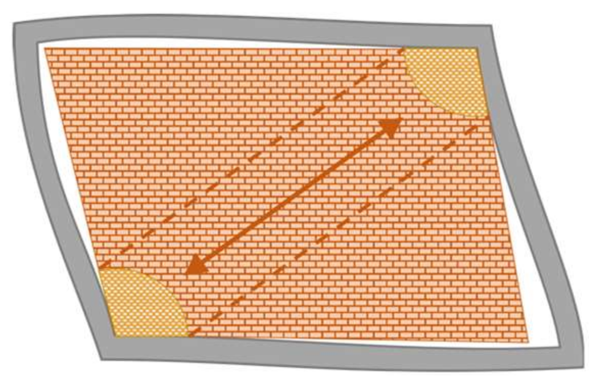
2.1.1. Diagonal Action

The strategy of substituting an infill wall with an equivalent diagonal strut to represent the influence of masonry panels on the IP response of infilled frames is the most effective and was originally presented in the literature by Polyakov in the early 1960s [3,8,9,36]. The infill walls deform in a shear mode, while the frame deformation is governed by a flexural mode. Due to this difference in the deformation patterns, during an earthquake excitation, Infill walls may partly detach from the frame before the walls collapse. The infill wall transfers a single-axis force diagonally between the opposite corners of the frame as a consequence of this gap (Figure 1). As a result, and due to this truss action mechanism in the panel, the infill is often idealised using diagonal struts [6,8].
Mohammad Noh et al. (2017) [64] investigated three different hysteretic models available in OpenSees [65]: Concrete01 material, Hysteretic material, and Pinching4 material for a single-strut macro-model, calibrated with two sets of experimental tests. They considered both distributed- and lumped-plasticity models for the RC frame members, finding out that the Pinching4 models was the optimal uniaxial constitutive material to replicate the cyclic response of infill walls, and that an excellent balance between precision and simplicity could be achieved with the Concrete01 material model available in OpenSees [65]. Additionally, the distributed-plasticity approach used for the RC members demonstrated its capability to represent the degradation of strength and stiffness, which is another non-negligible aspect.
Recent publications on the state of the art include a variety of infill wall macro-modelling methodologies employing the equivalent strut approach [3,8,9,64,66,67]. However, multiple diagonal struts have been developed in the early 1990s to replicate/mimic the behaviour of masonry infill walls because various features of the frame–wall interaction cannot be adequately reflected by a single diagonal strut [9], [36]. The numerical simulations suggest that a suitable infill wall macro-model for this purpose should have at least double struts [2].

2.1.2. Infill Wall–Frame Interaction

Because of insufficient shear and confinement reinforcement, concrete frames are often vulnerable to shear failure in columns and beams. In infilled frames, the interaction of the infill wall with the frame, which is another result of the infill–frame detachment, can further result in localised column shear failure. This failure mode, which depends on the infill’s strength, is a consequence of applied shear force on the column due to the lateral component of the diagonal force formed in the infill [6]. This shear failure often takes place at modest drift levels, even lower than in a bare frame, before flexural yielding of the columns, and might result in the loss of gravity load-bearing capacity of the columns [68,69]. This involves the infill wall’s ability to prevent the columns from experiencing substantial bending deformations.
The shear behaviour of columns under additional shear loads should be accurately predicted [6]. In the literature, one of the following methods is generally used to reach this goal, depending on how vulnerable the columns are expected to be to shear and on how complicated the modelling needs to be.
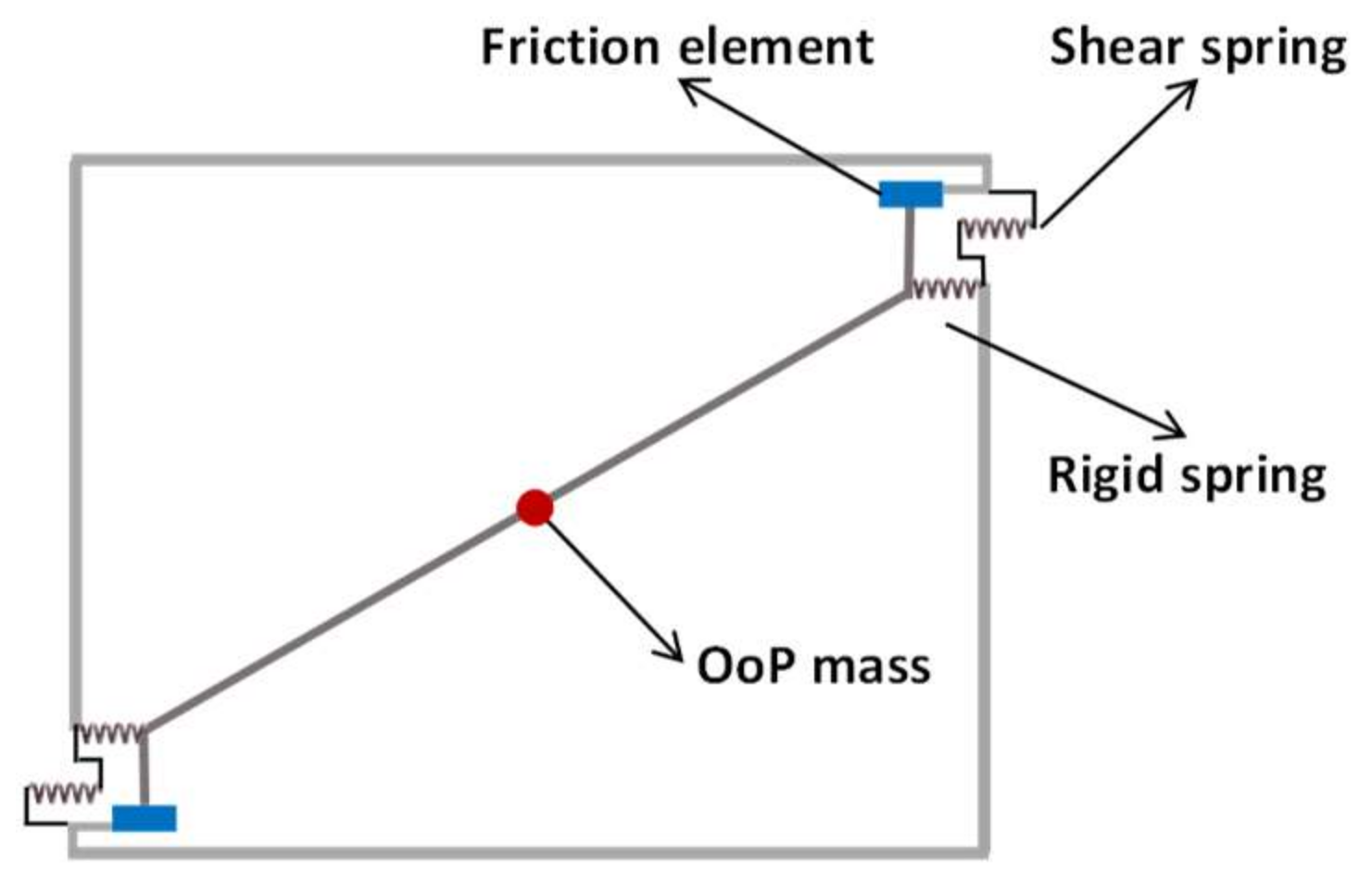
  • The use of nonlinear shear springs, usually a rigid softening material model;
  • the use of coupled shear-axial springs from Elwood (2004) [70], employed in Huang et al. (2020) [63];
  • the use of a shear spring that changes the shear strength depending on axial force.
Celarec and Dolšek (2013) [71] claimed that a considerable part—in some cases even half—of the horizontal component of the force in the diagonal strut is conveyed to the beam through friction. As such, the implementation of a friction element that transmits the force to the beam and a rigid spring for compatibility may enhance the modelling technique, as suggested by Mosalam and Günay (2015) [6] and shown in Figure 2.

2.2. OoP Behaviour

There have not been as many research studies looking at the OoP response of infill walls as there have been for the many experimental and analytical studies performed to understand the IP behaviour of infilled frames [59]. Recent experimental tests have been conducted to evaluate the OoP behaviour of infill walls both with and without considering prior IP damage, thus showing that the OoP capacity of the infill walls is mostly based on the highest level of lateral pressure (generally assumed as uniform along the infill’s height) that can cause a panel to collapse.

2.2.1. Flexural Action

A relationship that measures the displacement of the centre of a uniformly loaded elastic isotropic plate has been analytically derived from Timoshenko theory [72]. Using this relationship, it is possible to represent the infill wall’s initial stiffness until the first breaking point. It was the first estimate for the maximum lateral pressure causing collapse of the infill [4].
The proportional relationship of maximum lateral pressure q u might be determined using a linear elastic, isotropic, homogeneous material with tensile strength f t , thickness t , and height h [59]:
q u f t h t 2 ,
with a proportional coefficient depending on one-way or two-way action, aspect ratio, and restraint conditions of the panel. In fact, assuming the flexural regime governing the issue, the OoP capacity limit is achieved. As a result, the flexural tensile strength is referred to as the tensile capacity [59].

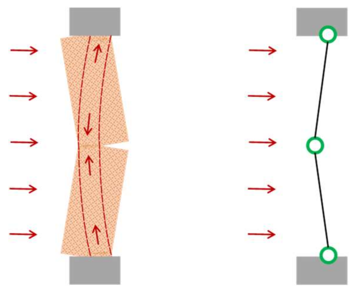
2.2.2. Arching Action

Experimental results [73,74,75,76,77] have shown that the main mechanism of resistance is the arching action that the infill walls can develop beyond the cracking deflection of the panel, and it was recommended to use a novel approach for the development of models [59]. As the initial cracks spread and widen, the panel sustains more significant damage. Two masonry blocks may turn as rigid bodies around their supported ends, which results in a gradual reduction of stiffness under rising OoP loads and the onset of three hinges and a resisting arch [4].
If this arch can develop, a resisting mechanism known as the “arching action” is responsible for the strength to OoP loads, first introduced by McDowell et al. (1956) [78] (Figure 3). When a limit state, which may be described as a maximal strain or stress, is reached at the outer compressed fibre, the developed arch collapses [4]. By ignoring the arching mechanism, the OoP strength is calculated at the point when the masonry tensile strength is reached at the outer fibre under tension.
Based on the different suggestions, the proportional relationship for determining the ultimate capacity can be expressed as:
q u f m h t 2 ,
The proportional coefficient depends on the thickness of the wall, the h / t ratio, the frame flexibility, the existence of openings inside the infill [79], and, in Angel et al. (2023) [80], the effect of IP prior loading. Since masonry’s compressive strength ( f m ) predominates over its tensile strength ( f t ), a higher ultimate load might be anticipated in comparison to flexural capacity.
FEMA356 (2000) [81] employs a more simplified and practical approach. The lower limit OoP strength of an infill wall must be evaluated as follows, if arching action is considered:
q u = 0.7 f m λ 2 h t ,
where, f m is the lower bound of masonry compressive strength, and λ 2 is the slenderness parameter, as defined in Table 1.
The code [81] states that arching action should be taken into account if all the following requirements are met. The panel is fully in touch with the components of the surrounding frame; in the most flexible member of the frame, the product of the elastic modulus, E f e , and the moment of inertia, I f , is more than 3.6 E 09 l b i n 2 ; the frame’s structural elements are strong enough to withstand thrusts caused by an infill wall’s arching; and the h / t ratio is not more than 25 . The first claim about the boundary conditions of infill walls appears to be the most important, as pointed out by Ricci et al. (2018) [4].
The common crack patterns seen following OoP experimental testing imply that the infill wall’s performance, which is constrained by the structural frame, may be compared to a plate’s behaviour. As a result, the arching phenomenon has a two-way generation [59]. Dawe and Seah (1989) [75] developed strength-based theories that took into account both two-way action and arching in the models and that were based on the virtual work principle. The effect of the support’s deformability was also considered in their investigation.

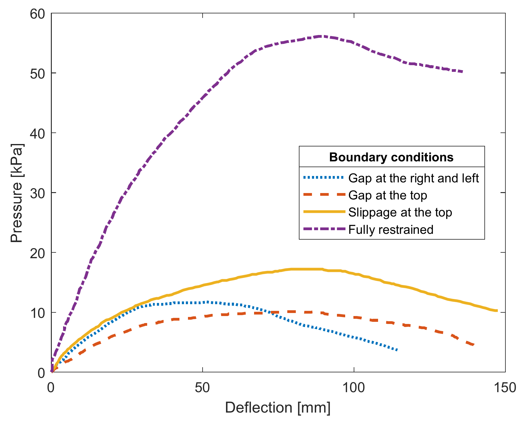
2.2.3. Boundary Conditions

As previously stated, the boundary conditions of infills are critical when it comes to the arching effect, as claimed by Shing et al. (2016) [82], who emphasised that a well-restrained infill on all sides is a requirement for a two-way generation of arching action. The findings of the experimental studies of Dawe and Seah (1989) [75] revealed that the boundary conditions have a considerable impact, demonstrating that the ultimate load capacity of panels with fully restrained infills was 4 5 times that of panels with gaps or where interfaces slipped (see Figure 4).
Di Domenico et al. (2019) [83] experimentally tested the OoP response of URM infills differently restrained at their edges. Along two, three, or four sides, they mortared the infill walls to the structural frame and showed that the type of boundary conditions drives the shape of the force-displacement response curves of the specimens. In the first case, a single-way vertical arching action formed. In the case where the wall was mortared on all sides, the OoP resistance was due to two-way (horizontal and vertical) arching action. One-way horizontal arching was initially seen in the wall specimen that was not in touch with the RC beam on the top, and then double arching was formed when the infill contacted the beam. It was also proven that two-way arching provides higher OoP strength than one-way arching.

2.3. IP–OoP Interaction

2.3.1. Overview

Infill walls are required to concurrently withstand IP and OoP actions due to the spatial variation of the ground—as well as floor—motion. This interaction may result in reciprocal damage [59].
It is granted that predicting how IP and OoP actions interact with damage modes is a complex issue [84]. Several experimental investigations on the infill walls’ OoP behaviour were carried out over the past 20 years (see, e.g., [55,77,83,85,86,87,88]) because of the understanding of their high seismic vulnerability, while only a small number of them, typically more recent ones, concentrated on the IP–OoP interaction [2]. However, using macro-element models, very little previous research has attempted to replicate the interactions between IP and OoP behaviour [1].
Despite that, several studies have been conducted on the interaction between IP and OoP forces in unreinforced masonry walls to obtain capacity interaction curves (see [89,90,91,92]). A comprehensive review of experimental studies by Gavilán et al. (2023) [37] covers the IP and OoP behaviour of confined masonry structures in many aspects in common with infills. However, as the main objective of this work is to review URM infill panels; the discussion of these studies is deferred to those who are specifically interested in that topic.
Studies showed that IP damage may have a considerable impact on the OoP strength and infill failure mechanisms [61]. IP damage can lead to a significant reduction in the panels’ OoP strength (by even half), depending on the slenderness ratios and the extent of the IP damage [80]. The IP displacement demand imposed by the structural frame may cause URM infill to separate from the surrounding frame during the early phases of seismic shaking [5]. Experiments have shown that the infills may collapse not because of a loss of strength but rather because of the instability caused by excessive OoP displacement [59]. The nonlinear finite element (FE) study conducted by Al-Chaar (2002) [79] revealed a substantial reduction in the IP capacity of infilled frames when subjected to OoP demands above 20 % of the OoP capacity.
The requirement for the creation of an integrative three-dimensional IP–OoP macro-model emerged as a result of the widespread use of time-history analysis for the evaluation of the seismic performance of structures. The primary goal was to update existing IP equivalent strut models so that the IP and OoP response, as well as their interaction, could potentially be predicted simultaneously. However, it was difficult to modify existing equivalent strut macro-models, and the incorporation of the two-way arching action presented the most significant challenges [59]. Therefore, there are still some seemingly unresolved issues with the evaluation of OoP behaviour and its reciprocal interaction with IP damage [82].

2.3.2. Codification Efforts

It is widely accepted that masonry infill walls create possibly serious problems for the seismic behaviour of structures since they are routinely categorised as non-structural components/elements and are frequently disregarded in the design process [2,3,10,11,12,15,29,56,57,93].
Because of limited awareness of the behaviour of semi-brittle materials in URM and the absence of convincing experimental and analytical data to support a trustworthy design technique for this kind of structure, infills are generally neglected throughout the design process [3,8,9]. Although there is experimental information in this area, there are no generally acknowledged standards for the modelling (and validation) of infills that contain consideration of their vulnerability, including their IP–OoP interaction [2]. However, due to the numerous interconnected factors, a modelling issue emerges when the infills are taken into account during the analysis and design procedure. This is because there are so many potential failure modes that must be assessed, and doing so with such a significant level of uncertainty can be challenging [9]. Based on experimental research, FEMA306 (1998) [94] offers an equation for the OoP infill strength that considers a reduction coefficient of the arching resisting capacity as a function of IP damage for the expedited IP–OoP verification of infill walls.

2.3.3. Macro/Micro-Modelling

Buildings with infilled frames are still being constructed quickly and regularly in many countries and developing nations around the world to keep up with increasing urbanisation needs. Therefore, the correct modelling of infills is crucial for determining their positive and negative impacts as well as for reliably assessing the seismic performance and vulnerability of these kinds of structures [6].
In the literature, a variety of methods, from simple macro-models to complicated micro-models, have been used to predict the behaviour of infilled frames [9]. In micro-models, the frame, the infill, and the interface between the frame and the infill wall can be modelled either in a continuum approach through nonlinear finite elements or in a discrete approach by means of the discrete element method. The constitutive models for this kind of modelling, which may be the most precise, involve a lot of data, and the considerable computing effort they need causes evaluation to be prolonged, especially for big/entire structures [5,64], particularly when it comes to integrating such modelling approach within frameworks for seismic fragility analysis. As a result, they are often only used to simulate single-infill panels [2]. Macro-models, on the other hand, are relatively simple and can predict the general infill force-deformation behaviour derived from experimental results with less computational cost, making them more suitable for simulating the general behaviour of entire structures [5,64]. A reduced quantity of variables, such as those related to the interaction between brick and mortar, is needed by macro-models since they employ fewer elements and do not distinguish between masonry units and joints [7,64]. Nonetheless, their calibration may be challenging to achieve [1,7,48].
As stated by Di Trapani et al. (2018) [1], appropriate macro-model specifications are as follows:
1.
The infill’s arching action under OoP loads must be taken into consideration in the model.
2.
The interaction between IP and OoP actions must be taken into consideration in the model; specifically, it must be taken into account how IP damage on infill may affect the OoP response and vice versa. In other words, the model should consider OoP strength and stiffness degradation due to IP damage and vice versa.
3.
The model must be simple enough to be used for static or dynamic analysis of an entire structural system.
More recently, macro-models have been developed with the intention of assessing the mixed IP and OoP behaviour of infills [59]. Among these, the first was that of Hashemi and Mosalam (2007) [60], which is discussed in what follows, soon after a brief review of common characteristics that available macro-modelling methodologies featuring IP–OoP interaction possess.

3. Macro-Modelling Approaches Featuring IP-OoP Interaction

Macro-models for the infill walls considering their IP-OoP interaction are provided chronologically in the following sub-sections, with one per each model concept. The structure and the idea behind each of these are explained in detail, and their advantages and drawbacks are mentioned subsequently. It is worth noting that the models under consideration in this paper have the following specifications:
  • all of these macro-models were developed using OpenSees [65];
  • each model represents a one-bay infill panel in a single storey frame;
  • the models are usable for a single-leaf infill;
  • the proposed models are validated for solid infills (without opening).

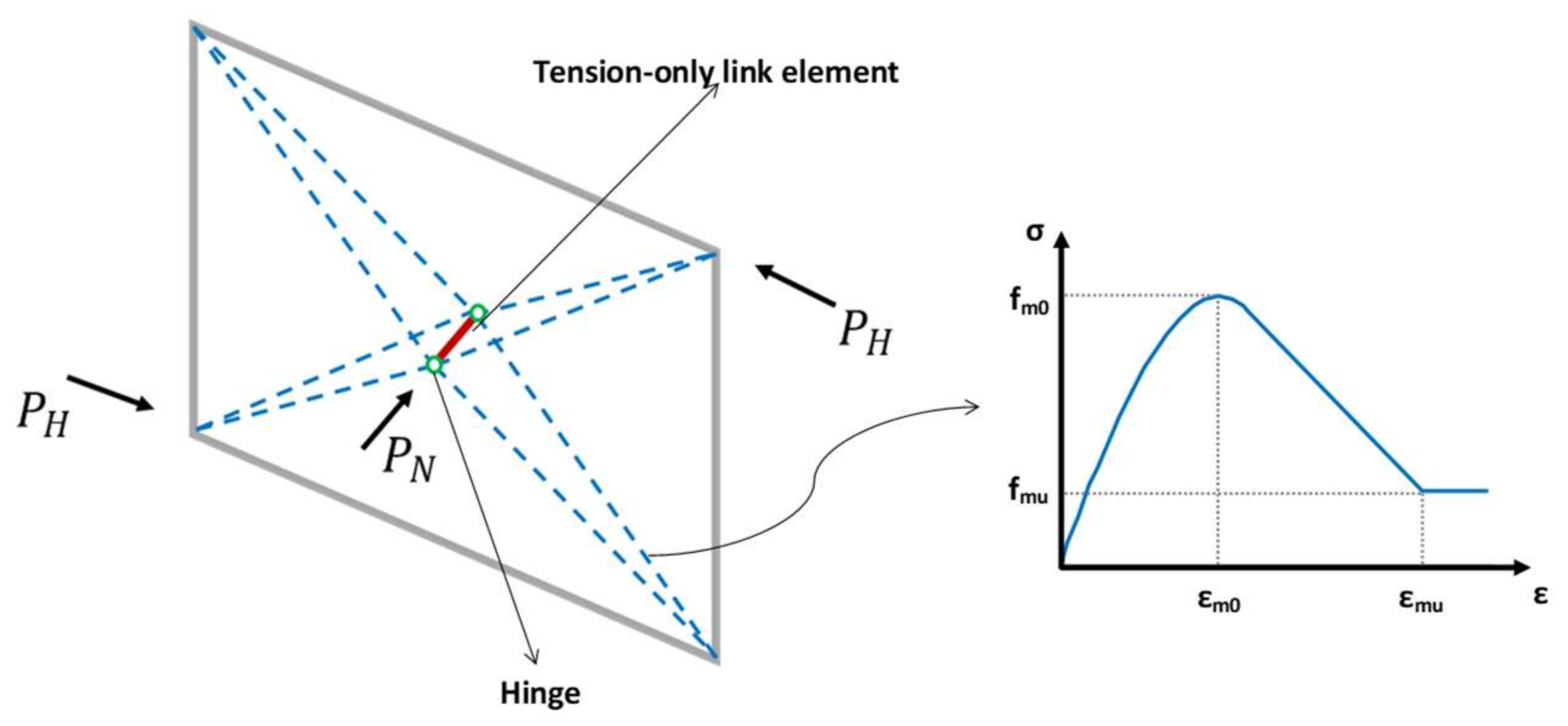
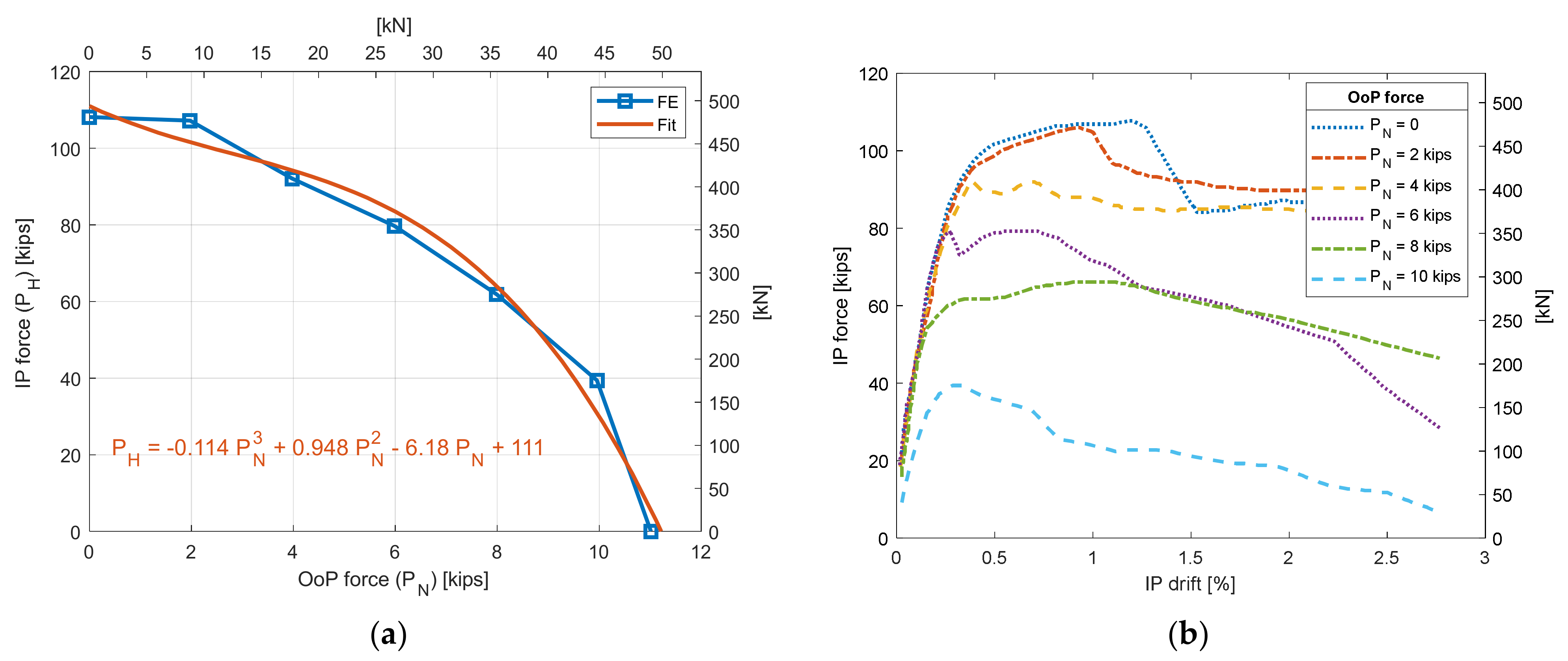
3.1. Strut-and-Tie (SAT) Model by Hashemi and Mosalam (2007) [60]

The first model that took into account the IP and OoP resistance of infills against coupled IP and OoP loads was provided by Hashemi and Mosalam (2007) [60]. A 3D strut-and-tie (SAT) system is used in this methodology to simulate the infill, as shown in Figure 5. The model features a double-diagonal strut, consisting of four pin-connected elements (eight resistant beams in total) with a specific compression-only stress-strain law. The diagonal struts are joined by a tie that is shared by both.
A tension-only elastic link element is shown in Figure 5 as a continuous line in the middle of the infill, whereas the dashed lines indicate nonlinear compression-only members. In order to reduce the capacity of the infill because of cyclic loading or prior damage, the material model for the link may be modified to tolerate permanent deformation caused by severe IP or OoP forces. This may be accomplished by loading and unloading the connecting element to the farthest point previously achieved on the plastic plateau while employing a rigid-plastic tension-only material. To distinguish between the infill’s before and after cracking behaviour, the hinges can be replaced with rotational springs with a specified moment capacity threshold corresponding to the beginning of cracking.
By moving each strut’s midspan joint normal to the plane of the infill, this model accounts for the arching action. This pioneering model provides a realistic method for simulating the OoP forces’ impact on the URM infill and the reciprocal interactions between the IP and OoP. The model is easy to use and can be adjusted to fit any failure surface found through testing or FE analysis.
A failure surface depicting the reciprocal IP-OoP damage status was defined as part of the model calibration process (Figure 6a). The formulation of this interaction domain was performed numerically using a FE model in DIANA [95], taking into account the outcomes of IP pushover analyses for various amounts of a constant OoP force (Figure 6b). If available, experimental data may be used for the calibration. It was discovered that a variety of factors, including the aspect ratio and the elastic and inelastic material characteristics in tension, had an impact on the interaction extent and the shape of the interaction curves [5].
Kadysiewski and Mosalam (2008) [49] discovered that this model displays several questionable responses in some circumstances. One is that it is feasible that the intended interaction curve will be violated by the IP and OoP force paths. Additionally, when significant IP displacement and high OoP loads are combined, the model may become unstable. Hysteretic damping and cyclic behaviour are further problems that should have been addressed. On the basis of these issues, Kadysiewski and Mosalam (2008) [49] proposed a different infill model, as described in Section 3.2.

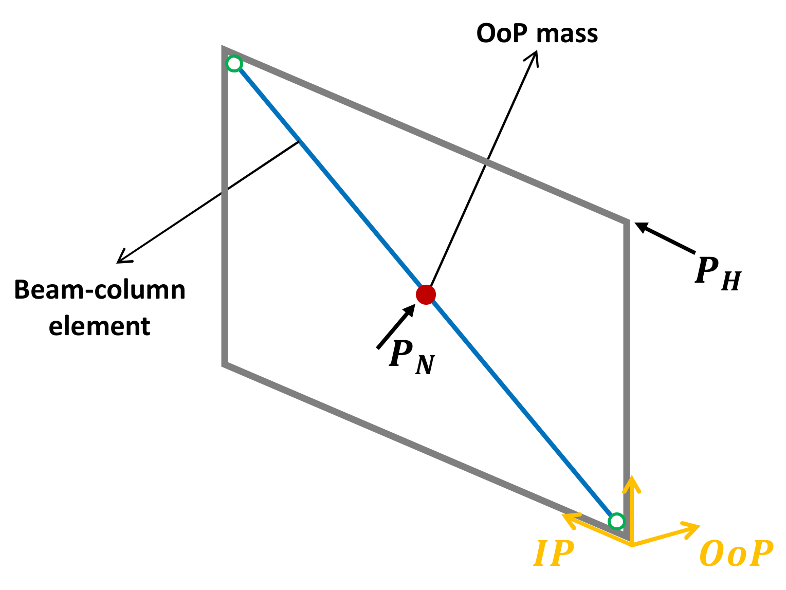
3.2. Single-Strut Model by Kadysiewski and Mosalam (2008) [48,49]

Considering the issues with the SAT infill model, another model was proposed by Kadysiewski and Mosalam (2008) [49] that uses fibre discretisation (Figure 7). This model clearly addresses the interaction between the IP and OoP through the cross section’s discretisation, making it simpler than the previous one in terms of the number of elements.
Kadysiewski and Mosalam (2008) [48,49] suggested a single-strut (one diagonal) model composed of two fibre-section beam-column elements joined at the centre node, where a lumped mass is allocated for the assessment of the behaviour of the infill panel in the OoP direction. The diagonal strut is given both tensile and compressive properties since utilising only one diagonal strut is enough to meet the IP–OoP interaction. The surrounding frame and the infill diagonal element are pin-connected. A nonlinear P M hinge is placed in the middle of the strut and produces the nonlinear behaviour using a fibre section.
It was intended for the model to have the following characteristics:
  • the model needs to include the required axial stiffness and strength for pure IP simulation;
  • the model’s natural period should be equal to that of the infill wall for OoP deflections;
  • for a certain support motion, the model has to provide the same OoP support reactions as the real infill wall;
  • at the same amount of excitation that makes the infill yield, the model should first yield in the OoP direction;
  • the model must display the defined IP-OoP interaction strength;
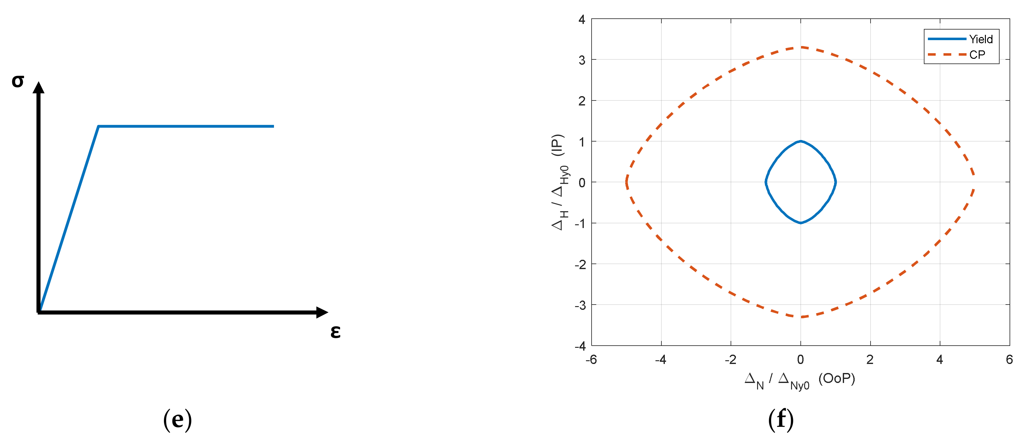
  • for the sake of simplicity, the model is intended to behave perfectly plastically in the post-yield area, meaning that there is no stress degradation in the material when strain increases.
In the previous model, Hashemi and Mosalam (2007) [60] presented a polynomial of third degree as an estimation of the IP–OoP interaction function based on a nonlinear FE model of the infill. In this model, the strength interaction curve is taken as a 3 / 2 -power curve, as provided below:
P N P N 0 3 2 + P H P H 0 3 2 1.0 ,
where P N is the OoP capacity in the presence of IP force, P N 0 is the OoP capacity without IP force, P H is the IP capacity in the presence of OoP force, and P H 0 is the IP capacity without OoP force. The proposed relationship is compared with the previously proposed third-degree polynomial, as well as the FE results, in Figure 8a. It is convex and shows a great fit to the FE outcomes.
For the OoP action, the ratio of bending moment strength may be used in lieu of the ratio of the force capacities since the elements are pinned to the frame. According to Figure 8b, which represents the chosen curve as a P M interaction, it is doubly symmetric. In fact, the assumption that the performance of the infill wall is the same for both IP and OoP is one of the problems with the development.
Following the interaction curve’s determination, the P M hinge calibration is examined in the cross section’s fibres by giving each fibre a unique set of material attributes. They are arranged symmetrically along the local z axis and with a distinct weight within the cross section (Figure 8c). To fit the intended IP-OoP failure curve, the properties of the fibres are allocated in terms of area A i , distance from the y axis z i , yielding strength F y i , and yielding strain y i using Equations (5) and (6):
F y i = 1 2 P j P j + 1 ,
z i = 1 2 M j + 1 M j F y i ,
P j is the axial IP load, and M j is the OoP moment strength of the cross section for the j t h point of the interaction curve (see Figure 8d).
To ensure numerical stability, all the fibres in OpenSees [65] are modelled as “hardening” materials with a tiny strain-hardening ratio (less than 1 % of the initial elastic tangent) (Figure 8e). The characteristics of fibres are therefore almost identical to those of an elastic-perfectly plastic material. There is a step-by-step computation for the infill fibre-section model in the study by Kadysiewski and Mosalam (2008) [49].
Infill failure criteria, used in this calibration as the “collapse prevention” (CP) level, were adopted from FEMA356 (2000) [81]. These criteria, which are based on the IP and OoP deformations of the infill, are given for unidirectional displacements only. Because the use of the 3 / 2 -power function for the yield displacement curve was deemed a reasonable assumption, Kadysiewski and Mosalam (2008) [49] chose to utilise the same relationship for the CP displacement, although more data would have been needed to justify this and show/quantify how IP and OoP collapse deformations interact (see Figure 8f and Equation (7)).
D I R t = Δ H ( t ) Δ H c p 0 3 2 + Δ N ( t ) Δ N c p 0 3 2 2 3 ,
In Equation (7), Δ H ( t ) is the IP deformation of the infill at time t, Δ H c p 0 is the IP deformation to cause the infill to reach CP in the absence of OoP deflection, Δ N ( t ) denotes the OoP deformation of the infill at time t, and Δ N c p 0 represents the OoP deformation making the infill reach CP in the absence of IP deflection.
According to Kadysiewski and Mosalam (2008) [49], one issue with their model is that it cannot achieve the desired sharp yield point for all loadings, despite the fact that the fibres are all elastic-perfectly plastic. This non-sharp yielding has the effect of causing certain fibres to yield before the deflections reach the yield surface on the displacement pathways or before the pair of IP forces and the OoP moment arrive at the interaction limit. This will lead to some unintended premature hysteretic damping. Kadysiewski and Mosalam (2008) [49] identified the following issue in their model when they discovered that the moment decreased after yielding but the axial force rose. They proposed changing the fibres’ post-yield characteristics to create post-yield model behaviour that is more consistent with empirically observed one.
The fact that the IP axial and OoP moment strengths do not completely decay when reaching the CP limit state in the interaction curve is a more significant problem with this model, as stated by Kadysiewski and Mosalam (2008) [49]. One option, they said, would be to change the analysis algorithm such that, when an element collapses, it is removed before continuing the analysis uninterrupted.

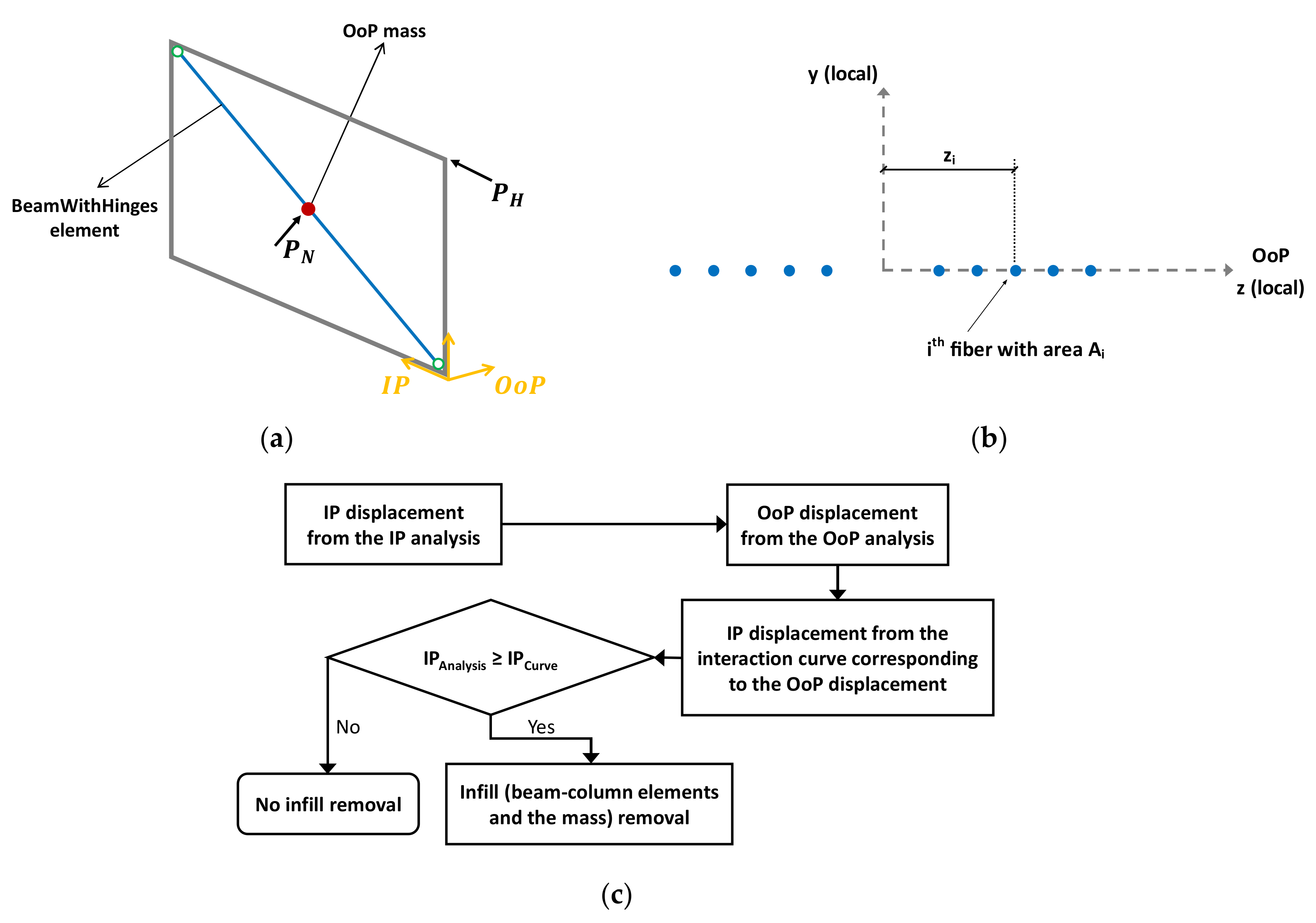
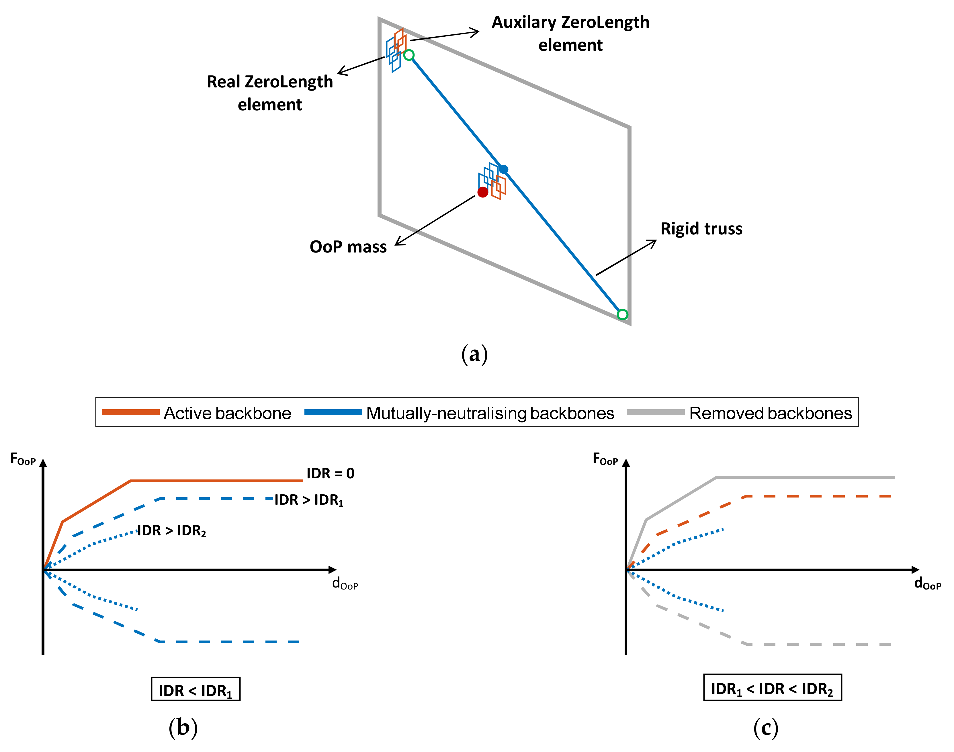
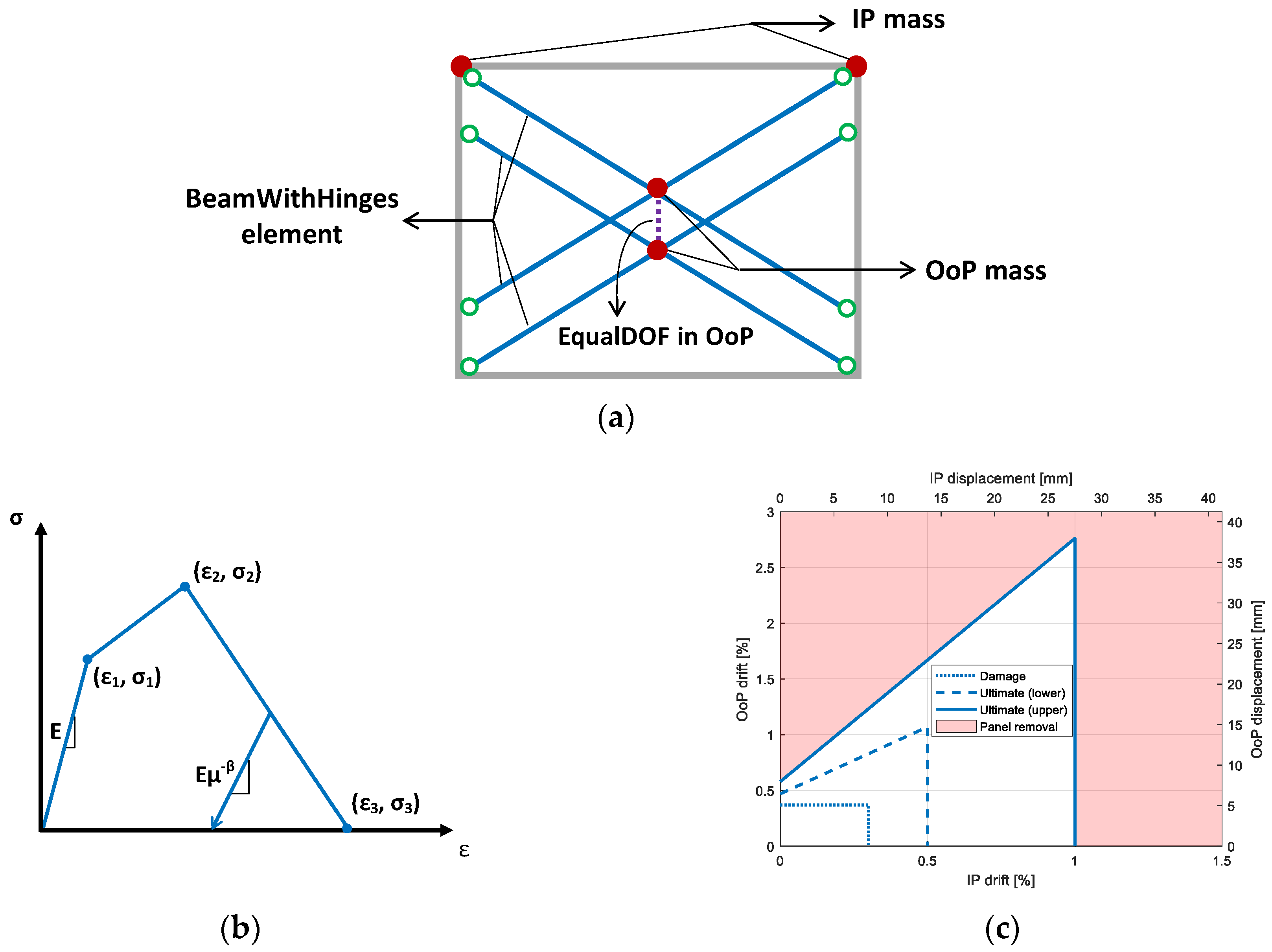
3.3. Single-Strut-Element Removal Model by Mosalam and Günay (2015) [6]

Mosalam and Günay (2015) [6] improved the previous model introduced by Kadysiewski and Mosalam (2008) [49] in two aspects. First, they added an element removal mechanism based on an IP–OoP displacement interaction curve to consider the failure of the infill wall. Second, they introduced column shear damage due to infill wall–column interaction.
Each infill in this model is defined by a single diagonal, joined at the centre with a mass allocated in the OoP direction, and is composed of two beam-column elements, known as “BeamWithHinges” in OpenSees [65] (Figure 9a). The element’s cross section is represented by placing nonlinear fibres across a single row that runs in the OoP direction (Figure 9b). As a result, in the IP and OoP directions, the beam-column element performs the roles of a truss element and a flexural member, respectively. The position and nonlinear properties of the fibres are chosen to achieve the desired strength interaction as well as the IP axial and OoP bending stiffness. In order to determine the IP stiffness and strength, equations from FEMA356 (2000) [81] are employed. According to the Kadysiewski and Mosalam (2008) [49] model, the OoP mass, stiffness, and bending strength are calculated to satisfy the aforementioned requirements about the fibre sections. The 3/2-power curve from the previous model is used to depict the strength interaction between IP axial and OoP bending.
The infill model was incorporated in a progressive collapse procedure created by Talaat and Mosalam (2009) [96] to consider the collapse of URM infills under combined IP and OoP actions. By introducing new criteria, that are established on the IP-OoP displacement interaction in the progressive collapse algorithm, as seen in Figure 9c, it is possible to deactivate the infill model [97]. As recommended by Kadysiewski and Mosalam (2008) [49], the displacement interaction is modelled using the same equation used for the strength interaction. Although using displacements to determine collapse is a reasonable option, choosing a 3 / 2 -power relationship should be supported by the results of tests to come. The two beam-column components and the central node, which represent the infill, are deleted to reflect the collapse of the infill when the IP and OoP displacement couple exceeds the curve limit.
In this model, nonlinear shear springs are added between the diagonal struts and the columns. This considers the horizontal forces applied from the infill to the columns as well as the potential column shear damage. This model employs the third model of a column’s shear behaviour, as listed in Section 2.1.2. This spring is modelled in OpenSees [65] as a uniaxial material, taking into account the ACI 318-08 (2008) [98] shear strength equations [99].
The damage development in this straightforward macro-model is tracked only in terms of significant masonry cracking and collapse of the infill. More computational models, and further experimental information regarding URM infill OoP ultimate displacements would have been needed to explain the panel wall response in depth with more substantial damage thresholds, to represent certain collapse mechanisms or damage distribution of the URM, or to explicitly include the arching action [5].
This model was implemented by Günay and Mosalam [97] in the open-source software framework OpenSees [65] and has been used in a number of subsequent studies, including, for instance, that by Longo et al. (2018) [5]. Another study, by Asteris et al. (2017) [59], listed the following drawbacks of the first three models introduced so far:
  • in either model, the arching motion is not explicitly taken into consideration;
  • in all three models, the assumption that fibres behave elastic-perfectly plastic results in fewer required parameters, but it also prevents cracks from forming. Consequently, any reduction in capacity beyond the maximum strength is unexpected for both IP and OoP behaviour;
  • due to the ambiguities about the real characteristics of the infill-frame structure, it is challenging to calibrate all of these models;
  • the second and third models provide a single-strut that can resist in both tension and compression, but this arrangement is incompatible with the system’s true physics and has an impact on how the internal forces are distributed in the frame.

3.4. Five-Beam Model by Furtado et al. (2016) [7]

Another simple macro-model to approximate the IP and OoP behaviour of infills was suggested by Furtado et al. (2016) [7]. This model is composed of five BeamWithHinges elements and two central nodes with panel mass, and it considers element removal mechanisms based on a displacement interaction curve (Figure 10a).
The model is based on a method developed by Rodrigues et al. (2010) [38] that was initially designed to just capture IP behaviour. Each infill in this model is represented by four rigid diagonal struts and a single centre element that mostly exhibits nonlinear hysteresis (five BeamWithHinges elements). The IP hysteretic behaviour may be simulated using the Pinching4 uniaxial material model. Two central nodes with evenly distributed masses— 0.405 of the panel mass for each—are inserted to mimic the OoP behaviour, and the behaviour is assumed to follow a linear elastic hysteretic curve.
The model adopts a different form for IP–OoP interaction to detect the damaged struts (Figure 10b), and it applies the same element removal procedure as in the model of [6] (Figure 10c). According to FEMA 356 (2000) [81], the collapse IP drift and collapse OoP drift are assumed to be 1.5 % and 3 % , respectively, for the undamaged panel in the linear domain. The five elements, as well as their associated central nodes and masses, are then eliminated.
Further research and calibrations are required to capture the true interaction that corresponds to the involved infill characteristics in the IP–OoP displacement interaction curve. This simplified macro-model does not account for the infill wall–frame interaction and, as a result, a potential short-column effect. For infilled frames where the short-column effect can be induced, a multiple-strut model strategy should be adopted.

3.5. Four-Element, Thickness Reduction Model by Oliaee and Magenes (2016) [47]

This model consists of four elements and a mass in the middle node. Each strut is composed of two different in-series elements, and the damage effect is considered through a thickness reduction of the elements instead of element removal, as clarified further hereinafter (Figure 11).
In this model, the infill wall is presented with two diagonals that each include two non-interacting, in-series, compression-only elements: an inelastic truss and a distributed-inelasticity fibre element that represent IP and OoP behaviour, respectively. The left diagonal halves (elements in the solid line in Figure 11) represent the IP behaviour, while the right diagonal halves (elements in the dashed line) provide the OoP resistance to inertial forces without compromising the IP behaviour. The IP–OoP interaction is designed in two phases: (i) modifying the strain of the fibres’ material at peak load to consider the OoP stiffness decay, and (ii) reducing the thickness of the elements to consider the OoP strength reduction. This approach simulates the dismissal of the outermost shell of masonry units caused by IP damage and is linearly dependent on the highest experienced IP displacement divided by the IP displacement pertaining to the limit state.
The IP elements are inelastic truss elements with modified compression-only stress-strain constitutive laws and original Crisafulli hysteresis rules. That is, there is a plateau where strength does not degrade after strain at maximal resistance. The OoP elements are displacement-based elements with distributed-inelasticity fibres. With a Kent-Park closing crack unloading rule, the uniaxial material at each fibre can only withstand compression stresses. The fibre elements experience arching action and withstand OoP load on the central node when they are subjected to double flexure. None of the four parts can withstand tension; instead, linear constraints on the extensibility of the fibre elements provide the boundary conditions with the beam columns and symmetry at the infill’s centre. Using this strategy, damage effects may be directly controlled since the OoP behaviour interacts with the IP reaction only through the interaction equations.
Specifically, the maximum compressive strain in the truss elements is used to compute the maximum IP drift, which is then adjusted at each time step by altering the material and section characteristics of the fibre elements. When the damage limit state is exceeded, the constitutive law of the material is revised by increasing the strain at peak strength ε 0 . Further than the damage limit state, a decrease in the thickness of the fibre section accounts for a reduction in the effective wall thickness, which then lowers the resistance to OoP loads because of flexural bending or arching action. The ratio between the IP drift and drift at the specified damage limit state is used to determine the amplification factor. Equation (8) is the relationship for how the stiffness of the panel changes in only the OoP direction.
ϵ 0 d m g ϵ 0 v i r g = δ m a x δ D L ,
where ε 0 d m g is the new strain at peak strength of the damaged material, ε 0 v i r g is the original strain at peak strength of the virgin material, δ m a x is the maximum inter-storey drift, and δ D L is the inter-storey drift of the damage limit state. The constitutive law and hysteretic characteristics of the nonlinear truss elements will determine how the IP stiffness/strength degrade.
The initial section thickness of the fibre elements is the same as the infill. Material loss from the masonry units’ outer shells seen in experimental investigations would point to a decrease in effective thickness leading to lower OoP stiffness through arching action. According to the damage limit inter-storey drift ratio, Equation (9) shows the thickness reduction beyond the damage limit state relative to the original wall thickness.
t r e d = 0.1 δ m a x δ D L 2 0 ,
It would also be helpful to include local effects caused by how the infill wall and frame members interact with each other.

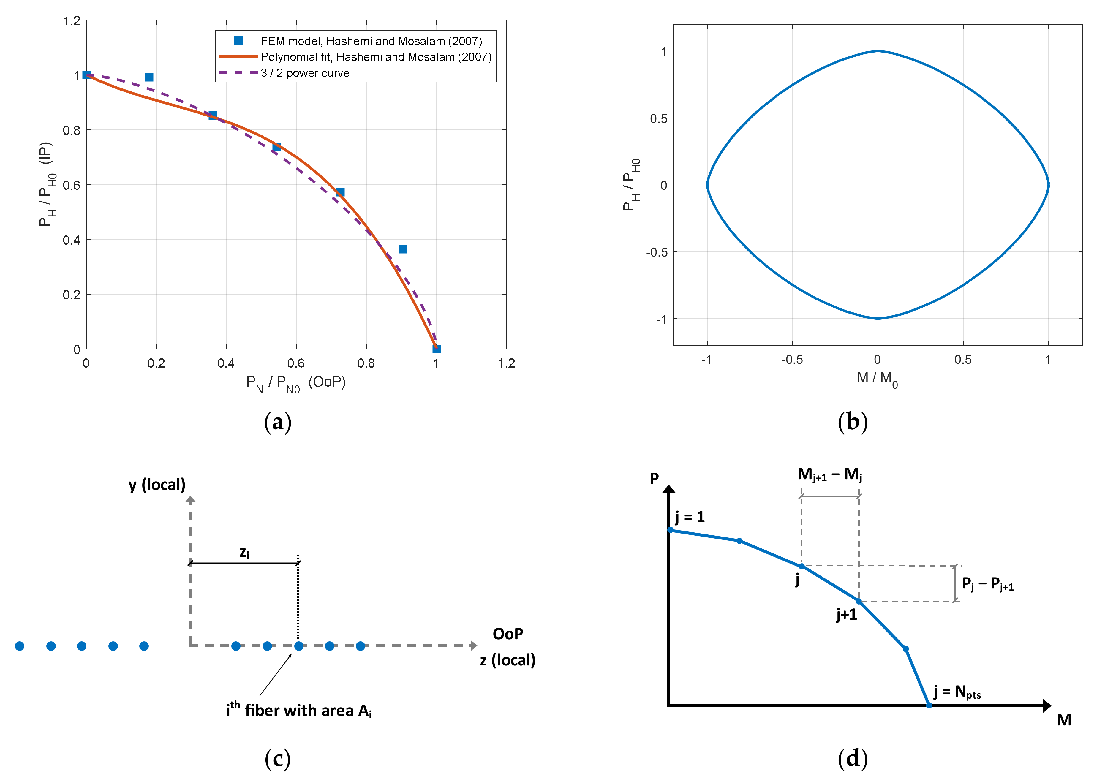
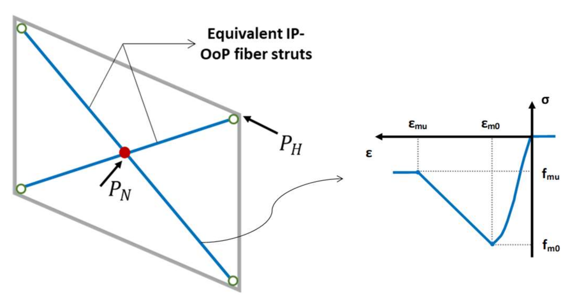
3.6. Equivalent IP–OoP Fibre Strut Model by Asteris et al. (2017) [44]

The first application of fully fibre section elements was provided by Asteris et al. (2017) [59], who considered the struts as fibre elements to account explicitly (and not only indirectly) for the arching action effect. As a way of explicitly accounting for the arching action, the usage of fibre-section elements with distributed plasticity utilised as diagonal struts may provide a highly desirable approach. The fact that these elements can be used to calculate a masonry beam’s flexural capacity makes them especially ideal for the task as a result of the coupled axial load and bending moment following the cracked phase.
This model takes into account a pair of diagonals, each of which is split by a joint in the centre (Figure 12). Nonlinear fibre elements that have been given a concrete-type constitutive material law compose the diagonals. This will allow for the recognition of the cracking of the cross sections in OoP and the neutral axis moving, which will consider the arching action. Whereas the fibre sections are able to account for the arching mechanism, the equivalent struts simultaneously match the IP and OoP strength and stiffness. The possible shear failure in column ends, due to the increase in shear demand locally, is incorporated with the aim of completely adaptive 3D modelling. This may be achieved simply by eccentrically positioning the struts and adding shear hinges at the column ends, as has previously been recommended by Stavridis and Shing (2014) [39].
The ability to create the numerical model without performing several prior computations to define the geometry of the struts is one benefit of using fibre elements to explicitly consider the arching action of infills under OoP load. The disadvantage of this model, however, is the need to identify the mechanical parameters that will characterise the compressive behaviour of the struts, as the empirical behaviour parameters are not based on a unified method. Therefore, this modelling methodology was proposed as a conceptual framework that still requires thorough structural diagnostic research and experimental confirmation, as admittedly acknowledged by the authors themselves.

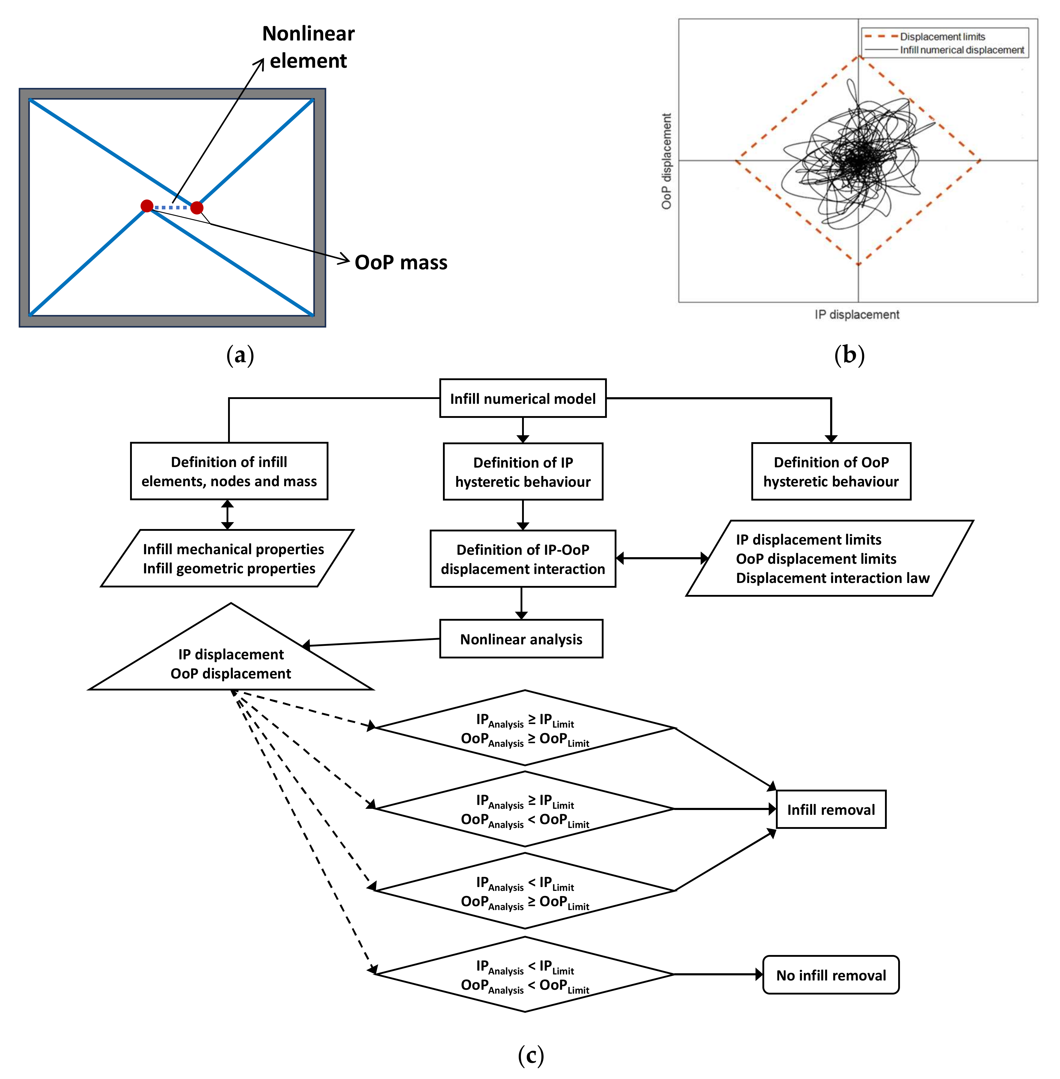
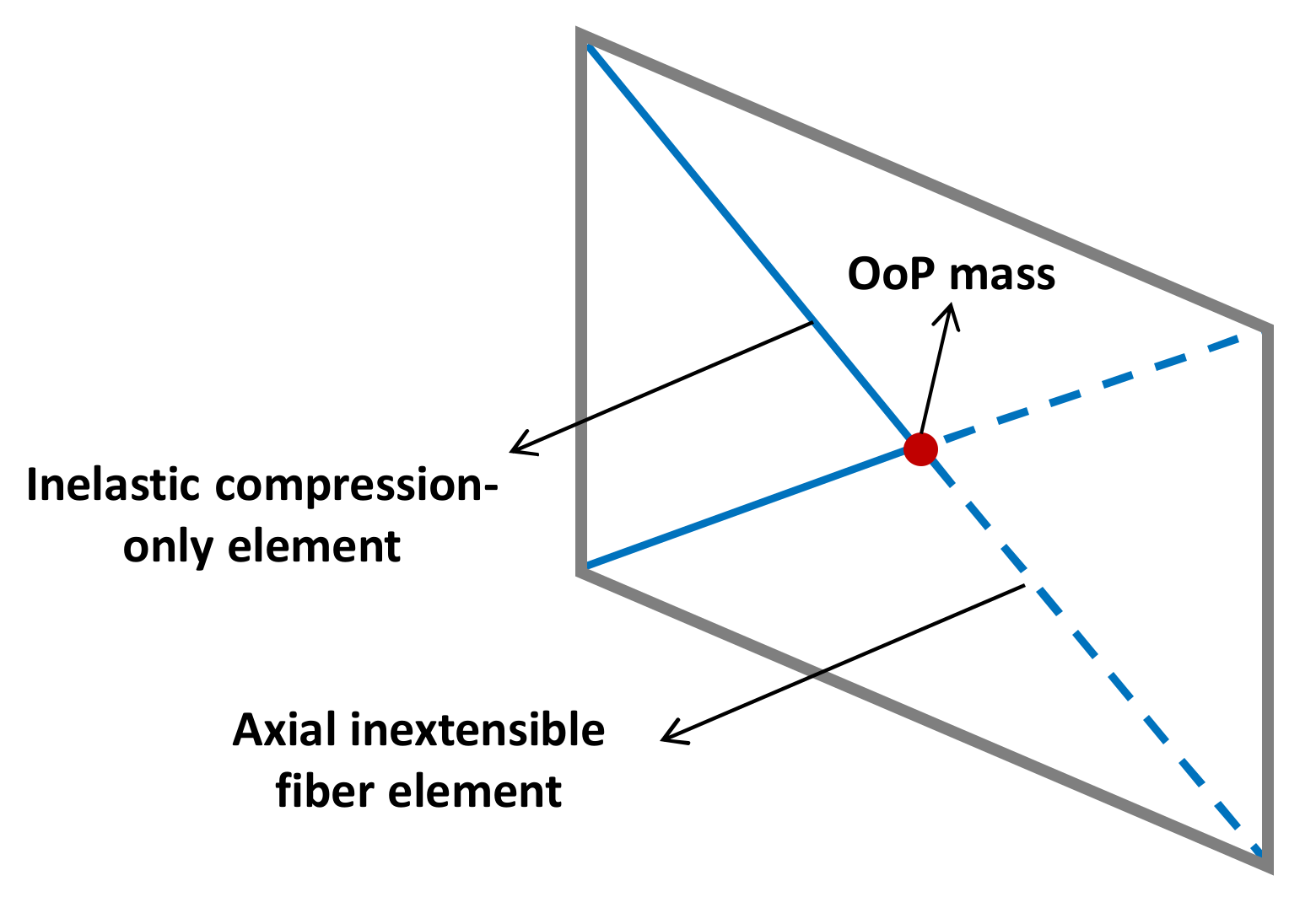
3.7. Four Pin-Jointed Strut Model by di Trapani et al. (2018) [1]

A model proposed by di Trapani et al. (2018) [1] added two struts to the model introduced by Asteris et al. (2017) [59] and constrained all the middle nodes to be able to shift together in the OoP (Figure 13).
Di Trapani et al. (2018) [1] suggested a four-strut macro-element model that not only considers the IP and OoP response of infills but also their interaction. This model comprises one horizontal, one vertical, and two diagonal struts, each of which is divided into two fibre beam-column elements made of Concrete02 material and joined by a node in the centre. This model has four central nodes, all of which may move individually in the IP direction, but all are constrained to move in the OoP direction together so that each strut can contribute to the OoP reaction.
The entire IP response of the infill wall and a large amount of the OoP capacity are provided by the diagonal struts. Although they do not affect the IP response, the vertical and horizontal struts provide a supplemental OoP contribution that reflects the two-way development of the arching action. This model uses empirical stress and strain parameters to describe the compressive behaviour of the non-oblique struts, whereas real infill wall strength and empirical values for the peak and ultimate strains are used to describe the compressive behaviour of the diagonals (Figure 13). The dimensions of the diagonals are determined by setting the width as 1 / 3 of the internal diagonal length and the thickness as the real value. Regardless of the relative stiffness of the infill wall and the frame, the “one-third” ratio was proposed as being appropriate [9].
In the case of slender struts, they considered the geometric nonlinearity of the beam-column elements to account for the significant displacement impact using the co-rotational coordinate transformation. To overcome the drawback of the model proposed by Asteris et al. (2017) [59], di Trapani et al. (2018) [1] attempted to get the empirical parameters for the IP analysis of infills using a correlation-based methodology. It can be observed that the model of di Trapani et al. (2018) [1] obtains compelling IP behaviour, despite OoP responses that are relatively less accurate [36].

3.8. Single-Strut Model by Ricci et al. (2018) [4]

This model adds several plastic hinges to the model proposed by Mosalam and Günay (2015) [6] for each of the IP and OoP behaviours and defines a step-by-step plastic hinge removal process using displacement criteria. Each infill in this model is depicted by a diagonal two-element that reflects the infill’s IP response (Figure 14a). Each of these elements has a node that connects to a lumped mass equal to the participating mass in the first OoP mode of vibration. It may be estimated to be 81 % of the infill’s overall mass in general [49]. In this model, 2 n + 1 plastic hinges are used to maintain the contact between these core nodes. It is necessary to construct a plastic hinge with the first backbone using a hysteretic material, and then to define two plastic hinges for each further backbone (Figure 14b,c).
When the IP inter-storey drift ratio goes higher than the formerly established damage threshold, a process in the model algorithm eliminates relevant plastic hinges from the model to reflect the resultant deterioration. This backbone removal strategy allows for modifying OoP behaviour due to IP action. Additionally, a second removal method is considered that removes all the infill elements from the model if the OoP displacement goes beyond the ultimate limit. The later removal approach is the same as that introduced by Mosalam and Günay (2015) [6] and then used by different researchers. The modelling of IP strength and stiffness degradation as well as the element removal due to IP drift is similar to the one explained for the OoP direction.
Even though it could become smoother as the number of considered backbones grows, the transition from one to the next cannot be completely smooth. Implementing interaction domains in the OpenSees [65] code may address this problem.

3.9. Modified Four-End Fixed-Strut Macro Model by Pradhan and Cavaleri (2020) [36]

This macro-model comes as an improvement of the model suggested by di Trapani et al. (2018) [1], with some modifications being made to improve the simulation’s accuracy for both the IP and OoP behaviour of the infills. The most important modifications consist in putting rotational restraints at the strut-frame joints and in using different cross sections for the equivalent struts (Figure 15).
The redesigned model keeps the same four-strut arrangement as the original one, which consists of two diagonal struts, one vertical strut, and one horizontal strut. Every strut in this model, as in the model of di Trapani et al. (2018) [1], is composed of two beam-column elements with fibre sections joined at the middle by a node. Between the suggested updated macro-model and the model of di Trapani et al. (2018) [1], the following significant differences can be listed:
  • In this model, rotation at the connection of all struts with the surrounding frame is constrained, unlike the model of di Trapani et al. (2018) [1], in which all struts are pinned to the frames. The middle span of a pin-ended strut has an early failure in flexure because of the excessive OoP deflection, which prevents the struts from fully arching. Rotational constraints at the ends of the struts improve the arching mechanism by preventing significant deflection at the struts’ centres and increasing compression at the ends.
  • In contrast to the model provided here, which uses a surrogate thickness value for all struts, the model proposed by di Trapani et al. (2018) [1] only uses the surrogate thickness value for the diagonal struts.
  • The compressive behaviour of all struts is defined in the proposed model using empirical strength, in contrast to employing an experimental compressive strength of panel for the non-oblique struts and an effective compressive strength for diagonal struts as in di Trapani et al. (2018) [1].
  • In contrast to the introduced model, which uses correlation equations to obtain the empirical stress-strain properties needed to simulate the compressive behaviour, the mechanical properties of the infill wall are defined empirically in the model by di Trapani et al. (2018) [1].
Geometric nonlinearity is considered in this model, as in the model of di Trapani et al. (2018) [1], using a co-rotational geometric transformation. In this model, each of the diagonal, horizontal, and vertical struts effectively participate in the OoP resistance. Comparing their contributions, Pradhan and Cavaleri (2020) [36] showed that the diagonal and vertical struts provide more OoP resistance than the horizontal struts. Although this model was validated to consider the influence of former IP damage on OoP response (but not vice versa), its ability to represent OoP behaviour was deemed more accurate than the model by di Trapani et al. (2018) [1].

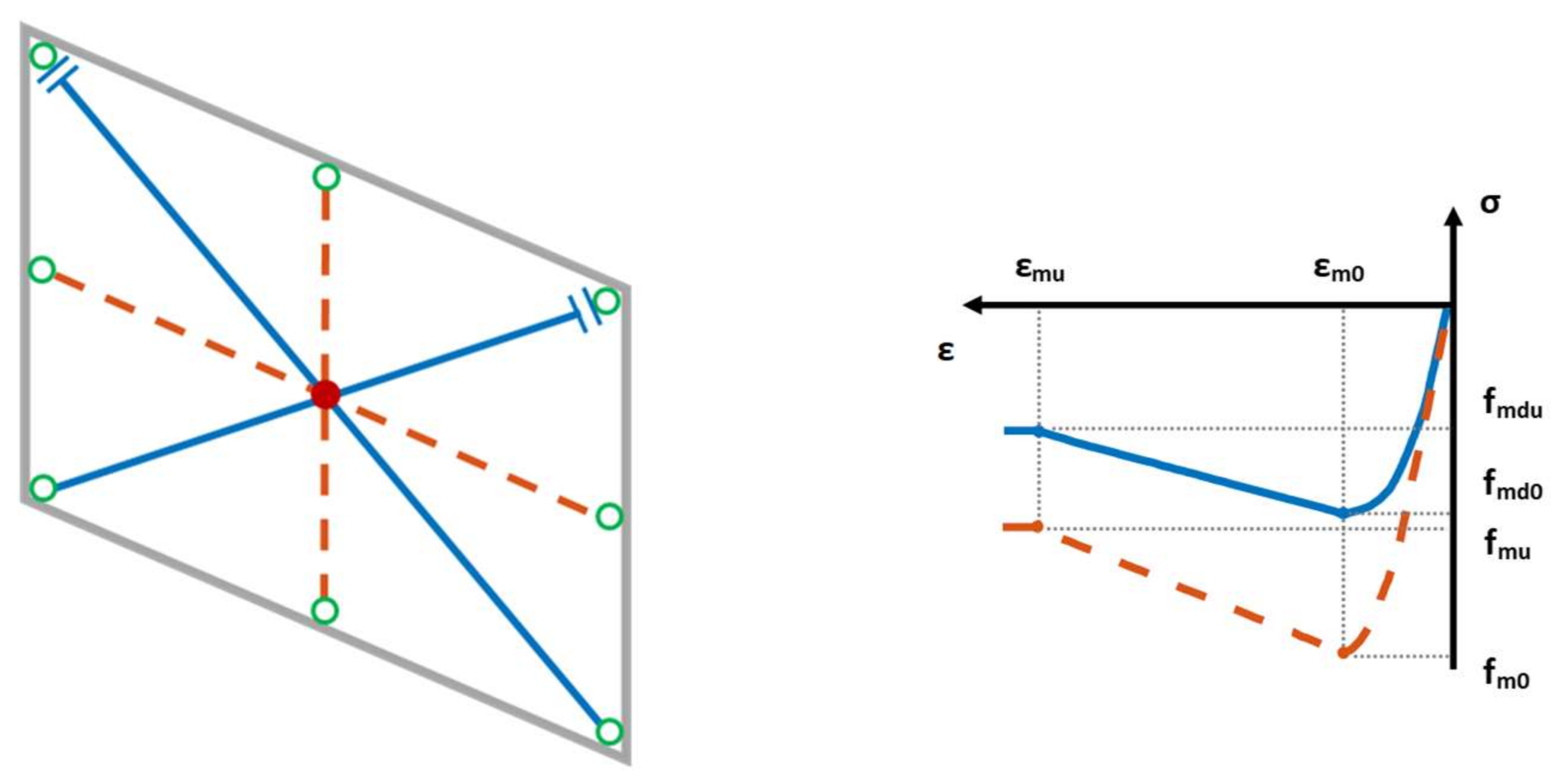
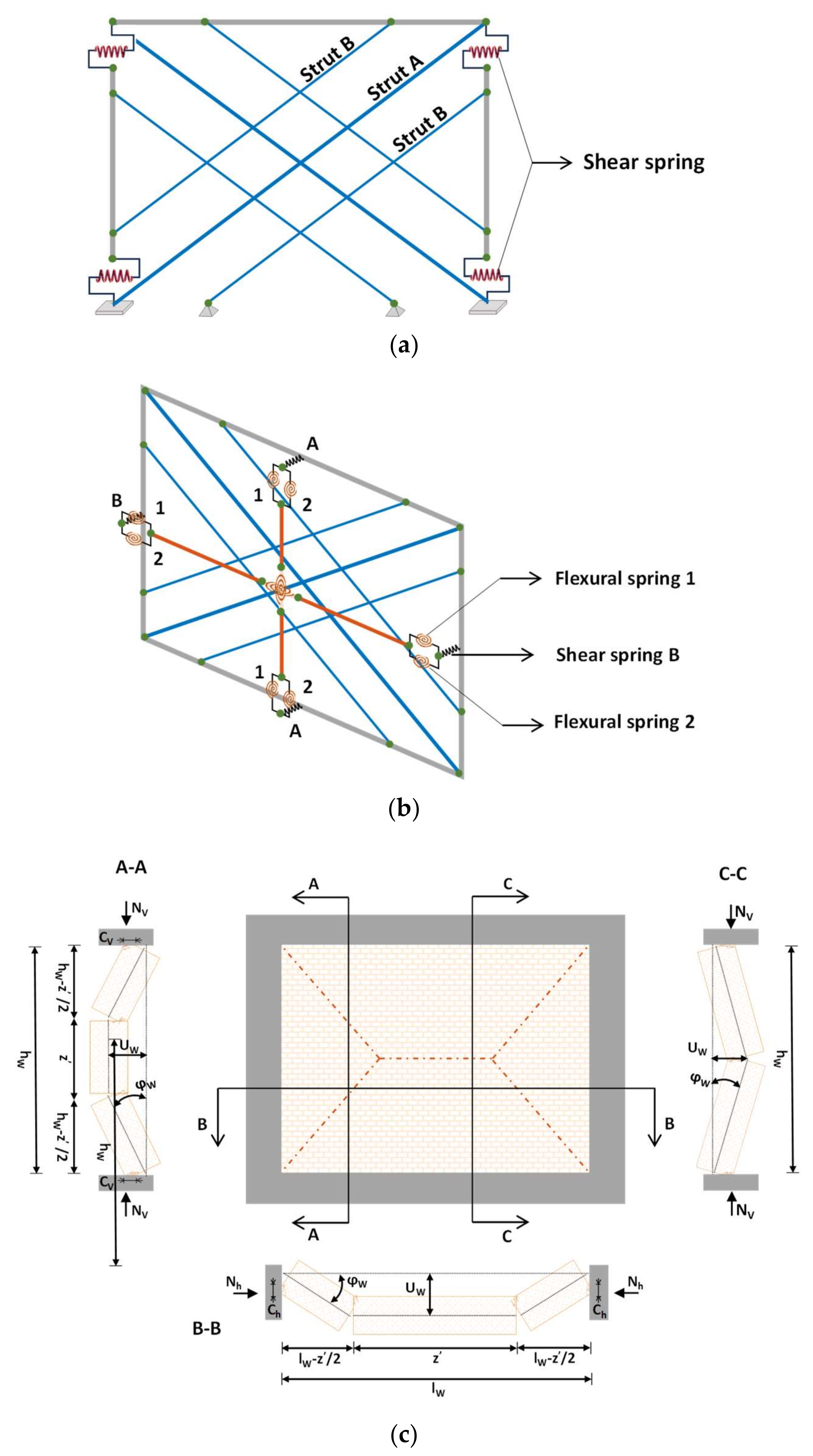
3.10. Four Off-Diagonal Struts Model by Donà et al. (2022) [2]

This fibre-based macro-model by Donà et al. (2022) [2] proposes a novel IP-OoP infill model derived from Mosalam and Günay (2015) [6]. This model is composed of two elements for each diagonal of the infill and two equal masses positioned in the middle (Figure 16a). The mass in the normal direction is used to activate the degree of freedom in the OoP direction, and each represents one-fourth of the overall mass of the wall. On the other hand, the wall mass in the IP direction is located on top of the columns. Each strut consists of two force-based beam-column elements. Nonlinear fibre sections with fibres placed in the OoP direction are modelled in the centre to create two central plastic hinges, where the nonlinearity caused by the IP–OoP interaction is concentrated. The struts are connected to the surrounding frame through linear hinge pins.
In the suggested macro-model, which is based on the concept of Mosalam and Günay (2015) [6], the fibres are instead defined by a tri-linear hysteretic compression-only material (Figure 16b). This modelling approach enables more accurate prediction of the nonlinear behaviour of the infills. Additionally, it enables the decoupling of the struts in IP, while the infill wall masses are coupled in the OoP direction using an EqualDOF command (i.e., translational kinematic constraints).
As in the model of Mosalam and Günay (2015) [6], the elastic behaviour of the infill is defined based on the IP–OoP interaction curve (Figure 8d). Unlike Mosalam and Günay (2015) [6], who computed the IP axial and OoP bending capacities in accordance with FEMA 356 (2000) [81], the values in this new model are calibrated based on experimental results for both elastic and post-elastic behaviour.
Upon entering a certain IP–OoP displacement region, a displacement control method is used to remove the infill elements. In this model, the interaction field is also calibrated experimentally and is quite different from the 3 / 2 -law domain proposed by Mosalam and Günay (2015) [6]. Donà et al. (2022) [2] defined infill limit states for various combinations of IP and OoP drifts, as shown in Figure 16c and Table 2.
To provide a richer evaluation of the IP–OoP interaction behaviour of different infills, the suggested model should be applied to more thorough time-history analyses, as admittedly conveyed by the same authors [2].

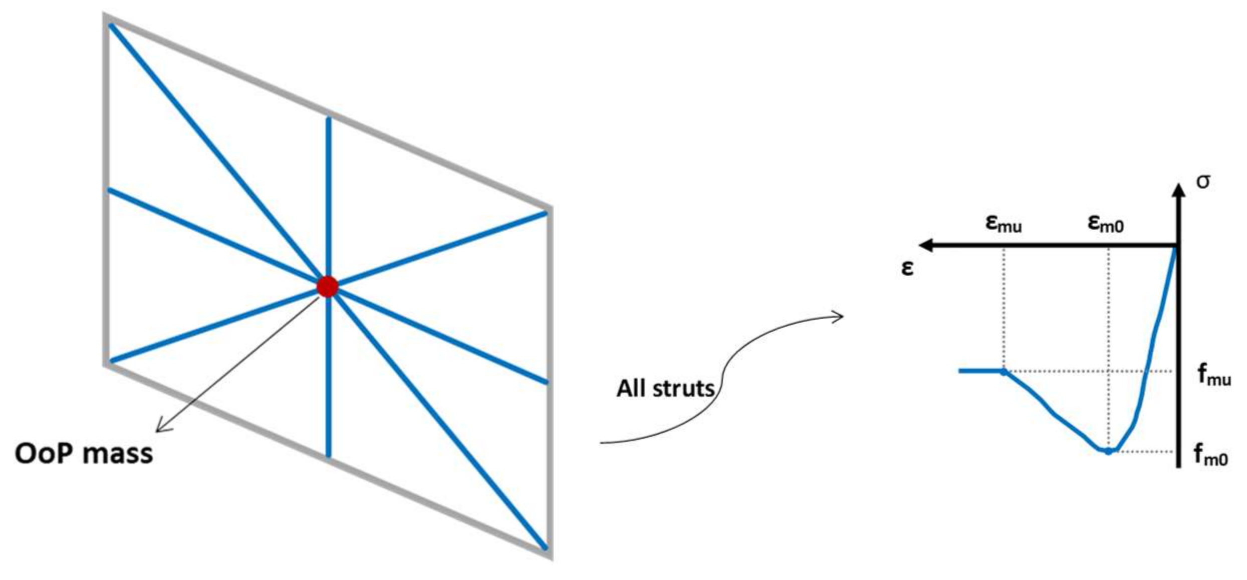
3.11. Six-Strut, Two-Beam Model by Blasi et al. (2022) [61]

The IP-OoP infill macro-model proposed by Blasi et al. (2022) [61] is based on the model introduced by di Trapani et al. (2018) [1] but includes infill–frame interaction and considers the resisting moment of the cross section of the masonry as well as the arching resisting mechanism. In this model, the IP behaviour of the infill wall is modelled using two sets of three diagonal struts to properly and conservatively predict the local IP interaction between the infill and the frame (Figure 17a) by their tri-linear compression-only constitutive law. As a result, the overall stiffness of the system is shared, with one-half going to the middle strut and the remaining half going to each off-diagonal strut equally, and shear springs having rigid-softening behaviour are located at the column ends.
Through two vertical and two horizontal beam elements, the OoP response of the infill is modelled in such a way that, to prevent affecting the IP response, their IP flexural and axial stiffness are both adjusted to a slight amount (Figure 17b). To replicate the nonlinear OoP flexural behaviour, these four beam elements are joined through a bi-directional zero-length flexural spring at the middle. Meanwhile, zero-length shear and flexural springs connect them to the surrounding frame.
To characterise these shear springs (A and B), a bilinear elastic softening behaviour is assumed to show the OoP failure of mortar connections at the contact between the infill and the frame. The flexural springs are located in parallel at the central node as well as between the frame elements and the infill elements. The moment–curvature relationship of the infill’s cross section is used to figure out the first spring (spring 1) with rigid-softening behaviour. By considering the maximum resisting moment as a result of the tensile strength of the masonry, this spring represents the crushing or cracking mechanism of the infill:
M w i m = σ c w l i w x w 12 3 t w 2 x w + f t w l i w t w x w 12 t w + 2 x w ,
where i indicates the rotation axis considered, and l i w is equal to either l w (moment around the x -axis) or h w (moment around the z -axis). Additionally, x w is the depth of the neutral axis, f t w is the tensile strength of masonry, t w is the thickness of the infill, and σ C W is the maximum compressive stress in masonry.
Using the method recommended by Dawe and Seah (1989) [75], which uses the principle of virtual work, the second kind of flexural spring (spring 2) is designed to provide moment-rotation behaviour as a result of the arching mechanism (Figure 17c). The total internal virtual work δ W i , as a result of the vertical and horizontal internal forces, is presented in Equations (11) and (12).
δ W i v = 2 0 h w 2 2 N w v . φ w t w c v + u w z h w 1 d x + 0 l w h w 2 N w v . φ w t w c v + u w d x ,
δ W i h = 2 0 h w 2 2 N w h . φ w t w c h + u w z l w h w d z ,
where N W V and N W h are the vertical and horizontal axial forces generated by the arching mechanism, respectively; c v and c h are the depths of the compressed region of the infill’s cross section in the vertical and horizontal directions, respectively; and u w is the OoP displacement of the infill at mid-height. The external work is computed with q e x t as the external unit loads, F e x t , j as the external point loads, and u w , j as the external displacement corresponding to F e x t , j .
δ W e = 0 h w 0 l w q e x t . u x , z w d x d z + F e x t , j . u w , j
The used modelling strategy requires that IP and OoP elements representing the infill do not interact with each other. Most of the experimental studies considering the IP-OoP interaction consider the OoP response after imposing IP damage. Therefore, the previously introduced models characterise the degradation of OoP behaviour as a function of IP drift. The objective of this model, however, is to examine the impact of infill wall OoP deflection on IP deterioration. To account for the interaction between IP and OoP behaviour, a real-time modification of the mechanical properties of IP truss elements, depending on the OoP damage extent of the infill wall, is defined. With the assumption of zero IP strength at the OoP failure of the infill wall, five linear steps are considered for IP strength and stiffness degradation based on the ratio of OoP deformation.
This model uses multi-struts, namely three struts for each diagonal, as well as shear springs to capture the added shear actions on the columns, which together generate the most accepted approach to simulate the IP behaviour of infill panels. Moreover, many significant OoP damage modes, such as arching action, shear failure at the infill-frame joint, and flexural failure of the cross section of the masonry, are predicted in this model. However, further research is necessary to confirm the idea of using a linear dependency of the IP strength/stiffness degradation to the OoP drift, which seems to be connected to the dearth of experimental support. Another issue is that this model considers parallel springs to account for flexural and arching actions. As previously described, an arching mechanism can develop beyond the cracking deflection. One solution may be deploying a gap element for the arching action.

4. Closing Remarks

This paper provides a review of current numerical modelling practices for simulating the behaviour of unreinforced solid masonry infills accounting for the interaction of in-plane (IP) and out-of-plane (OoP) responses under earthquake-induced actions. More specifically, after giving an overview on a series of behavioural aspects, 11 macro-modelling approaches available in the literature were revisited and scrutinised extensively. Each modelling strategy evidently has benefits and disadvantages that should be compared, bearing in mind issues of calibration difficulties, computational costs, application range, and simulation precision.
Multiple-strut models are deemed more effective because they can more accurately represent the distribution of forces in the entire frame and take into account the local interactions between the infill wall and the surrounding frame; in this respect, readers are referred to the models by Donà et al. (2022) [2] and Blasi et al. (2022) [61]. Elements with nonlinear fibre sections are likely to be the best choice because they simulate the arching mechanism explicitly, not just indirectly (see, for instance, the models by di Trapani et al. (2018) [1], Pradhan and Cavaleri (2020) [36], and Asteris et al. (2017) [59]). Limiting the elements to consider only one of the IP and OoP actions, or in other words, decoupling IP and OoP actions, not only makes the model further away from simulating the real IP-OoP interaction but also causes subsequent issues in estimating the reciprocal effects. Focussing on the arching mechanism and partial infill wall-frame separation during earthquake excitation, it is theoretically possible to form diagonal arching. Although no experimental studies are available at the moment in this regard due to the complexity of the simulation, many of the models are deemed capable of capturing this action. However, only the models by di Trapani et al. (2018) [1], Pradhan and Cavaleri (2020) [36], Asteris et al. (2017) [59], and Blasi et al. (2022) [61] are meant to be able to simulate the two-way arching mechanism. Regarding the boundary conditions, the model proposed by Blasi et al. (2022) [61] properly gives the option to simulate different conditions at the interface between the infill wall and the surrounding frame, even in special cases like slip and delayed connection, which may result in a one-way arching action followed by a two-way arching mechanism.
With respect to their frequency of usage, the models under evaluation in this paper were incrementally developed over a period of 16 years, with the bulk of them (9 out of 11) being introduced during the latter half of the initial model’s lifespan. It is anticipated/expected that as experimental research on the actual interaction between IP–OoP advances in the future, all of these models will attain even greater maturity and completeness, and the accuracy of all or part of them will be even further scrutinised and/or backtracked.
In closing, it is noted further that the models presented and scrutinised in this paper were concerned with solid infill walls, bringing into question the issue of how these models can adapt/handle the case of infills with openings, the latter being equally seen as a limitation of the models or a research gap/need for reliable seismic performance assessment at a structure level.

Author Contributions

Conceptualization, S.R., S.P. and E.B.; methodology, S.R., S.P. and E.B.; validation, S.R., S.P. and E.B.; formal analysis, S.R.; investigation, S.R.; resources, S.P.; data curation, S.R.; writing—original draft preparation, S.R.; writing—review and editing, S.P. and E.B.; supervision, S.P. and E.B. All authors have read and agreed to the published version of the manuscript.

Funding

This study was developed under the auspices of the Italian Department of Civil Protection and within the activities of the Eucentre-DPC 2022–2023 research programme, WP14 “Caratterizzazione della risposta sismica di elementi non strutturali”. The authors would like to express their gratitude to the Italian Department of Civil Protection for the financial support received through a two-year framework programme established with the European Centre for Training and Research in Earthquake Engineering.

Conflicts of Interest

The authors declare no conflict of interest. The funders had no role in the design of the study; in the collection, analyses, or interpretation of data; in the writing of the manuscript; or in the decision to publish the results.

References

  1. Di Trapani, F.; Shing, P.B.; Cavaleri, L. Macroelement model for in-plane and out-of-plane responses of masonry infills in frame structures. J. Struct. Eng. 2018, 144, 04017198. [Google Scholar] [CrossRef]
  2. Donà, M.; Minotto, M.; Verlato, N.; da Porto, F. A new macro-model to analyse the combined in-plane/out-of-plane behaviour of unreinforced and strengthened infill walls. Eng. Struct. 2022, 250, 113487. [Google Scholar] [CrossRef]
  3. Crisafulli, F.J.; Carr, A.J.; Park, R. Analytical modelling of infilled frame structures—A general review. Bull. N. Z. Soc. Earthq. Eng. 2000, 33, 30–47. [Google Scholar] [CrossRef]
  4. Ricci, P.; Di Domenico, M.; Verderame, G.M. Empirical-based out-of-plane URM infill wall model accounting for the interaction with in-plane demand. Earthq. Eng. Struct. Dyn. 2018, 47, 802–827. [Google Scholar] [CrossRef]
  5. Longo, F.; Wiebe, L.; da Porto, F.; Modena, C. Application of an in-plane/out-of-plane interaction model for URM infill walls to dynamic seismic analysis of RC frame buildings. Bull. Earthq. Eng. 2018, 16, 6163–6190. [Google Scholar] [CrossRef]
  6. Mosalam, K.M.; Günay, S. Progressive collapse analysis of reinforced concrete frames with unreinforced masonry infill walls considering in-plane/out-of-plane interaction. Earthq. Spectra 2015, 31, 921–943. [Google Scholar] [CrossRef]
  7. Furtado, A.; Rodrigues, H.; Arêde, A.; Varum, H. Simplified macro-model for infill masonry walls considering the out-of-plane behaviour. Earthq. Eng. Struct. Dyn. 2016, 45, 507–524. [Google Scholar] [CrossRef]
  8. Tarque, N.; Candido, L.; Camata, G.; Spacone, E. Masonry infilled frame structures: State-of-the-art review of numerical modelling. Earthq. Struct. 2015, 8, 225–251. [Google Scholar] [CrossRef]
  9. Asteris, P.G.; Antoniou, S.T.; Sophianopoulos, D.S.; Chrysostomou, C.Z. Mathematical macromodeling of infilled frames: State of the art. J. Struct. Eng. 2011, 137, 1508–1517. [Google Scholar] [CrossRef]
  10. Calvi, G.M.; Bolognini, D. Seismic response of reinforced concrete frames infilled with weakly reinforced masonry panels. J. Earthq. Eng. 2001, 5, 153–185. [Google Scholar] [CrossRef]
  11. El-Dakhakhni, W.W.; Hamid, A.A.; Hakam, Z.H.R.; Elgaaly, M. Hazard mitigation and strengthening of unreinforced masonry walls using composites. Compos. Struct. 2006, 73, 458–477. [Google Scholar] [CrossRef]
  12. Celarec, D.; Ricci, P.; Dolšek, M. The sensitivity of seismic response parameters to the uncertain modelling variables of masonry-infilled reinforced concrete frames. Eng. Struct. 2012, 35, 165–177. [Google Scholar] [CrossRef]
  13. Hak, S.; Morandi, P.; Magenes, G.; Sullivan, T.J. Damage control for clay masonry infills in the design of RC frame structures. J. Earthq. Eng. 2012, 16, 670575. [Google Scholar] [CrossRef]
  14. Cavaleri, L.; Di Trapani, F. Cyclic response of masonry infilled RC frames: Experimental results and simplified modeling. Soil Dyn. Earthq. Eng. 2014, 65, 224–242. [Google Scholar] [CrossRef]
  15. Sassun, K.; Sullivan, T.J.; Morandi, P.; Cardone, D. Characterising the in-plane seismic performance of infill masonry. Bull. N. Z. Soc. Earthq. Eng. 2016, 49, 98–115. [Google Scholar] [CrossRef]
  16. Morandi, P.; Hak, S.; Magenes, G. Performance-based interpretation of in-plane cyclic tests on RC frames with strong masonry infills. Eng. Struct. 2018, 156, 503–521. [Google Scholar] [CrossRef]
  17. Surana, M.; Pisode, M.; Singh, Y.; Lang, D.H. Effect of URM infills on inelastic floor response of RC frame buildings. Eng. Struct. 2018, 175, 861–878. [Google Scholar] [CrossRef]
  18. De Risi, M.T.; Del Gaudio, C.; Ricci, P.; Verderame, G.M. In-plane behaviour and damage assessment of masonry infills with hollow clay bricks in RC frames. Eng. Struct. 2018, 168, 257–275. [Google Scholar] [CrossRef]
  19. Ricci, P.; Di Domenico, M.; Verderame, G.M. Experimental assessment of the in-plane/out-of-plane interaction in unreinforced masonry infill walls. Eng. Struct. 2018, 173, 960–978. [Google Scholar] [CrossRef]
  20. Perrone, D.; Brunesi, E.; Filiatrault, A.; Nascimbene, R. Probabilistic estimation of floor response spectra in masonry infilled reinforced concrete building portfolio. Eng. Struct. 2020, 202, 109842. [Google Scholar] [CrossRef]
  21. Mucedero, G.; Perrone, D.; Brunesi, E.; Monteiro, R. Numerical modelling and validation of the response of masonry infilled rc frames using experimental testing results. Buildings 2020, 10, 182. [Google Scholar] [CrossRef]
  22. Furtado, A.; Rodrigues, H.; Arêde, A. Effect of the infill panels in the floor response spectra of an 8-storey RC building. Structures 2021, 34, 2476–2498. [Google Scholar] [CrossRef]
  23. Manfredi, G.; Prota, A.; Verderame, G.M.; De Luca, F.; Ricci, P. 2012 Emilia earthquake, Italy: Reinforced concrete buildings response. Bull. Earthq. Eng. 2014, 12, 2275–2298. [Google Scholar] [CrossRef]
  24. Cardone, D.; Perrone, G. Damage and loss assessment of Pre-70 RC frame buildings with FEMA P-58. J. Earthq. Eng. 2017, 21, 23–61. [Google Scholar] [CrossRef]
  25. O’Reilly, G.J.; Perrone, D.; Fox, M.; Monteiro, R.; Filiatrault, A. Seismic assessment and loss estimation of existing school buildings in Italy. Eng. Struct. 2018, 168, 142–162. [Google Scholar] [CrossRef]
  26. Blasi, G.; De Luca, F.; Aiello, M.A. Brittle failure in RC masonry infilled frames: The role of infill overstrength. Eng. Struct. 2018, 177, 506–518. [Google Scholar] [CrossRef]
  27. Rossi, A.; Morandi, P.; Magenes, G. A novel approach for the evaluation of the economical losses due to seismic actions on RC buildings with masonry infills. Soil Dyn. Earthq. Eng. 2021, 145, 106722. [Google Scholar] [CrossRef]
  28. Mucedero, G.; Perrone, D.; Monteiro, R. Nonlinear static characterisation of masonry-infilled RC building portfolios accounting for variability of infill properties. Bull. Earthq. Eng. 2021, 19, 2597–2641. [Google Scholar] [CrossRef]
  29. Mucedero, G.; Perrone, D.; Monteiro, R. Seismic risk assessment of masonry-infilled RC building portfolios: Impact of variability in the infill properties. Bull. Earthq. Eng. 2023, 21, 957–995. [Google Scholar] [CrossRef]
  30. Vicente, R.S.; Rodrigues, H.; Varum, H.; Costa, A.; da Silva, J.A.R.M. Performance of masonry enclosure walls: Lessons learned from recent earthquakes. Earthq. Eng. Eng. Vib. 2012, 11, 23–34. [Google Scholar] [CrossRef]
  31. Hashmi, A.K.; Madan, A. Fragility analysis of infilled reinforced concrete frames subjected to near-field ground motions. KSCE J. Civ. Eng. 2020, 24, 122–130. [Google Scholar] [CrossRef]
  32. Gautam, D.; Adhikari, R.; Rupakhety, R. Seismic fragility of structural and non-structural elements of Nepali RC buildings. Eng. Struct. 2021, 232, 111879. [Google Scholar] [CrossRef]
  33. Sathurshan, M.; Thamboo, J.; Mallikarachchi, C.; Wijesundara, K. Seismic fragility of lightly reinforced concrete school building typologies with different masonry infill configurations. Structures 2023, 47, 1710–1728. [Google Scholar] [CrossRef]
  34. Jeon, J.S.; Park, J.H.; Desroches, R. Seismic fragility of lightly reinforced concrete frames with masonry infills. Earthq. Eng. Struct. Dyn. 2015, 44, 1783–1803. [Google Scholar] [CrossRef]
  35. FEMA E-74. Reducing the Risks of Nonstructural Earthquake Damage—A Practical Guide. 2012. Available online: http://www.fema.gov/earthquake-publications/fema-e-74-reducing-risks-nonstructural-earthquake-damage (accessed on 15 July 2023).
  36. Pradhan, B.; Cavaleri, L. IP-OOP interaction in URM infilled frame structures: A new macro-modelling proposal. Eng. Struct. 2020, 224, 111211. [Google Scholar] [CrossRef]
  37. Escalante, J.J.P.G.; Brzev, S.; Cazarin, E.F.E.; Ganzerli, S.; Quiun, D.; Reiter, M.T. Experimental research studies on seismic behaviour of confined masonry structures: Current status and future needs. Buildings 2023, 13, 1776. [Google Scholar] [CrossRef]
  38. Rodrigues, H.; Varum, H.; Costa, A. Simplified macro-model for infill masonry panels. J. Earthq. Eng. 2010, 14, 390–416. [Google Scholar] [CrossRef]
  39. Stavridis, A.; Shing, P.B. Analysis of seismic response of masonry-infilled RC frames through collapse. ACI Struct. J. 2014, 297, 1–20. [Google Scholar]
  40. Sattar, S. Influence of Masonry Infill Walls and Other BUILDING characteristics on Seismic Collapse of Concrete Frame Buildings. Ph.D. Thesis, University of Colorado, Boulder, CO, USA, 2013. [Google Scholar]
  41. Furtado, A.; Rodrigues, H.; Arêde, A.; Varum, H. Experimental evaluation of out-of-plane capacity of masonry infill walls. Eng. Struct. 2016, 111, 48–63. [Google Scholar] [CrossRef]
  42. Palieraki, V.; Zeris, C.; Vintzileou, E.; Adami, C.E. In-plane and out-of plane response of currently constructed masonry infills. Eng. Struct. 2018, 177, 103–116. [Google Scholar] [CrossRef]
  43. Marinković, M.; Butenweg, C. Experimental testing of decoupled masonry infills with steel anchors for out-of-plane support under combined in-plane and out-of-plane seismic loading. Constr. Build. Mater. 2022, 318, 126041. [Google Scholar] [CrossRef]
  44. Manfredi, V.; Masi, A. Combining in-plane and out-of-plane behaviour of masonry infills in the seismic analysis of RC buildings. Earthq. Struct. 2014, 6, 515–537. [Google Scholar] [CrossRef]
  45. Morandi, P.; Hak, S.; Milanesi, R.R.; Magenes, G. In-plane/out-of-plane interaction of strong masonry infills: From cyclic tests to out-of-plane verifications. Earthq. Eng. Struct. Dyn. 2022, 51, 648–672. [Google Scholar] [CrossRef]
  46. Mazza, F.; Donnici, A. In-plane and out-of-plane seismic damage of masonry infills in existing r.c. structures: The case study of De Gasperi-Battaglia school in Norcia. Bull. Earthq. Eng. 2021, 19, 345–376. [Google Scholar] [CrossRef]
  47. Oliaee, M.; Magenes, G. In-plane—Out-of-plane interaction in the seismic response of masonry infills in RC frames. In Proceedings of the 16th International Brick and Block Masonry Conference (IBMAC 2016), Padova, Italy, 26–30 June 2016; Modena, C., da Porto, F., Valluzzi, M.R., Eds.; CRC Press: London, UK, 2016; pp. 1309–1316. [Google Scholar]
  48. Kadysiewski, S.; Mosalam, K.M. Modelling of unreinforced masonry infill walls considering in-plane and out-of-plane interaction. In Proceedings of the 11th Canadian Masonry Symposium, Toronto, ON, Canada, 31 May–3 June 2009; Available online: http://canadamasonrydesigncentre.com/download/11th_symposium/C4-3.pdf (accessed on 15 July 2023).
  49. Kadysiewski, S.; Mosalam, K.M. Modelling of Unreinforced Masonry Infill Walls Considering In-Plane and Out-of-Plane Interaction; PEER 2008/102; University of California: Berkeley, CA, USA, 2008; Available online: https://peer.berkeley.edu/sites/default/files/web_peer8102_stephen_kadysiewski_khalid_m._mosalam_.pdf (accessed on 15 July 2023).
  50. Milanesi, R.R.; Morandi, P.; Hak, S.; Magenes, G. Experiment-based out-of-plane resistance of strong masonry infills for codified applications. Eng. Struct. 2021, 242, 112525. [Google Scholar] [CrossRef]
  51. Braga, F.; Manfredi, V.; Masi, A.; Salvatori, A.; Vona, M. Performance of non-structural elements in RC buildings during the L’Aquila, 2009 earthquake. Bull. Earthq. Eng. 2011, 9, 307–324. [Google Scholar] [CrossRef]
  52. Inel, M.; Ozmen, H.B.; Akyol, E. Observations on the building damages after 19 2011 Simav (Turkey) earthquake. Bull. Earthq. Eng. 2013, 11, 255–283. [Google Scholar] [CrossRef]
  53. Masi, A.; Chiauzzi, L.; Santarsiero, G.; Manfredi, V.; Biondi, S.; Spacone, E.; Del Gaudio, C.; Ricci, P.; Manfredi, G.; Verderame, G.M. Seismic response of RC buildings during the Mw 6.0 24 August 2016 Central Italy earthquake: The Amatrice case study. Bull. Earthq. Eng. 2019, 17, 5631–5654. [Google Scholar] [CrossRef]
  54. Perrone, D.; Calvi, P.M.; Nascimbene, R.; Fischer, E.C.; Magliulo, G. Seismic performance of non-structural elements during the 2016 Central Italy earthquake. Bull. Earthq. Eng. 2019, 17, 5655–5677. [Google Scholar] [CrossRef]
  55. Akhoundi, F.; Vasconcelos, J.G.; Lourenco, P.; Silva, L.M. Out-of-plane response of masonry infilled RC frames: Effect of workmanship and opening. In Proceedings of the 16th International Brick and Block Masonry Conference (IBMAC 2016), Padova, Italy, 26–30 June 2016; Modena, C., da Porto, F., Valluzzi, M.R., Eds.; CRC Press: London, UK, 2016; pp. 1147–1154. [Google Scholar]
  56. Tasligedik, A.S.; Pampanin, S.; Palermo, A. Damage mitigation strategies of ‘non-structural’ infill walls: Concept and numerical-experimental validation program. In Proceedings of the 9th Pacific Conference on Earthquake Engineering, Building an Earthquake-Resilient Society, Paper Number 120; Civil and Natural Resources Engineering; University of Canterbury: Auckland, New Zealand, 2011. [Google Scholar]
  57. Negro, P.; Colombo, A. Irregularities induced by nonstructural masonry panels in framed buildings. Eng. Struct. 1997, 19, 576–585. [Google Scholar] [CrossRef]
  58. Liberatore, L.; Decanini, L.D.; Liberatore, D. Seismic lateral deformation and energy demands in bare and infilled RC frames. In Proceedings of the 13th World Conference on Earthquake Engineering, Paper 7007, Vancouver, BC, Canada, 1–6 August 2004. [Google Scholar]
  59. Asteris, P.G.; Cavaleri, L.; Di Trapani, F.; Tsaris, A.K. Numerical modelling of out-of-plane response of infilled frames: State of the art and future challenges for the equivalent strut macromodels. Eng. Struct. 2017, 132, 110–122. [Google Scholar] [CrossRef]
  60. Hashemi, A.; Mosalam, K.M. Seismic Evaluation of Reinforced Concrete Buildings Including Effects of Masonry Infill Walls (PEER Report 2007/100); University of California: New York, NY, USA, 2007. [Google Scholar]
  61. Blasi, G.; Perrone, D.; Aiello, M.A. In-plane and out-of-plane model for retrofitted infill walls in reinforced concrete framed buildings. Bull. Earthq. Eng. 2022, 20, 8277–8304. [Google Scholar] [CrossRef]
  62. Soroushian, P.; Kienuwa, O.; Ki-Bong, C. Nonlinear modeling and seismic analysis of masonry shear walls. J. Struct. Eng. 1988, 114, 1106–1119. [Google Scholar] [CrossRef]
  63. Huang, H.; Burton, H.V.; Sattar, S. Development and utilization of a database of infilled frame experiments for numerical modeling. J. Struct. Eng. 2020, 146, 04020079. [Google Scholar] [CrossRef]
  64. Noh, N.M.; Liberatore, L.; Mollaioli, F.; Tesfamariam, S. Modelling of masonry infilled RC frames subjected to cyclic loads: State of the art review and modelling with OpenSees. Eng. Struct. 2017, 150, 599–621. [Google Scholar] [CrossRef]
  65. McKenna, F.; Fenves, G.L.; Scott, M.H. Open System for Earthquake Engineering Simulation (OpenSees); University of California: Berkeley, CA, USA, 2000; Available online: http://opensees.berkeley.edu (accessed on 15 July 2023).
  66. Crisafulli, F.J.; Carr, A.J. Proposed macro-model for the analysis of infilled frame structures. Bull. N. Z. Soc. Earthq. Eng. 2007, 40, 69–77. [Google Scholar] [CrossRef]
  67. Sattar, S.; Liel, A.B. Seismic performance of nonductile reinforced concrete frames with masonry infill walls—II: Collapse assessment. Earthq. Spectra 2016, 32, 819–842. [Google Scholar] [CrossRef]
  68. Burton, H.; Deierlein, G. Simulation of seismic collapse in nonductile reinforced concrete frame buildings with masonry infills. J. Struct. Eng. 2014, 140, A4014016. [Google Scholar] [CrossRef]
  69. Sattar, S.; Liel, A.B. Seismic performance of nonductile reinforced concrete frames with masonry infill walls—I: Development of a strut model enhanced by finite element models. Earthq. Spectra 2016, 32, 795–818. [Google Scholar] [CrossRef]
  70. Elwood, K.J. Modelling failures in existing reinforced concrete columns. Can. J. Civ. Eng. 2004, 31, 846–859. [Google Scholar] [CrossRef]
  71. Celarec, D.; Dolšek, M. Practice-oriented probabilistic seismic performance assessment of infilled frames with consideration of shear failure of columns. Earthq. Eng. Struct. Dyn. 2013, 42, 1339–1360. [Google Scholar] [CrossRef]
  72. Timoshenko, S.; Woinowsky-Krieger, S. Theory of Plates and Shells, 2nd ed.; McGraw-Hill Book Company Inc.: New York, NY, USA, 1959. [Google Scholar]
  73. Lönhoff, M.; Dobrowolski, C.; Sadegh-Azar, H. Analysis of the out-of-plane capacity of unreinforced masonry infill walls. Procedia Eng. 2017, 199, 693–698. [Google Scholar] [CrossRef]
  74. Kariotis, J.C. Methodology for Mitigation of Seismic Hazards in Existing Unreinforced Masonry Buildings: Wall Testing, Out-of-Plane; ABK-A Joint Venture: EI Segundo, CA, USA, 1981. [Google Scholar]
  75. Dawe, J.L.; Seah, C.K. Out-of-plane resistance of concrete masonry infilled panels. Can. J. Civ. Eng. 1989, 16, 854–864. [Google Scholar] [CrossRef]
  76. Flanagan, R.D.; Bennett, M.R. Arching of masonry infilled frames: Comparison of analytical methods. Pract. Period. Struct. Des. Constr. 1999, 4, 105–110. [Google Scholar] [CrossRef]
  77. Derakhshan, H.; Griffith, M.C.; Ingham, J.M. Airbag testing of multi-leaf unreinforced masonry walls subjected to one-way bending. Eng. Struct. 2013, 57, 512–522. [Google Scholar] [CrossRef]
  78. McDowell, E.L.; McKee, K.E.; Sevin, E. Arching action theory of masonry walls. J. Struct. Div. 1956, 82, 1–8. [Google Scholar] [CrossRef]
  79. Al-Chaar, G. Evaluating Strength and Stiffness of Unreinforced Masonry Infill Structures. Washington, DC, USA. 2002. Available online: https://www.researchgate.net/publication/235149444 (accessed on 15 July 2023).
  80. Angel, R.; Abrams, D.; Shapiro, D.; Uzarski, J.; Webster, M. Behaviour of Reinforced Concrete Frames with Masonry Infills. 1994. Available online: https://www.researchgate.net/publication/39066987_Behavior_of_Reinforced_Concrete_Frames_with_Masonry_Infills (accessed on 15 July 2023).
  81. FEMA 356. Prestandars and COMMENTARY for the SEISMIC REHABILITATION of BUILDINGS. 2000. Available online: https://www.fema.gov/sites/default/files/2020-08/fema_earthquakes_prestandard-and-commentary-for-the-seismic-rehabilitation-of-buildings-fema-p-356.zip (accessed on 15 July 2023).
  82. Shing, P.S.; Cavaleri, L.; Di Trapani, F. Prediction of the out-of-plane response of infilled frames under seismic loads by a new fiber-section macro-model. In Proceedings of the 16th International Brick and Block Masonry Conference (IBMAC 2016), Padova, Italy, 26–30 June 2016; Barreto, M.F.O., Brandão, P.R.G., Eds.; CRC Press: Boca Raton, FL, USA, 2016; pp. 1427–1432. [Google Scholar] [CrossRef]
  83. Di Domenico, M.; Ricci, P.; Verderame, G.M. Experimental assessment of the out-of-plane strength of URM infill walls with different slenderness and boundary conditions. Bull. Earthq. Eng. 2019, 17, 3959–3993. [Google Scholar] [CrossRef]
  84. Liberatore, L.; AlShawa, O.; Marson, C.; Pasca, M.; Sorrentino, L. Out-of-plane capacity equations for masonry infill walls accounting for openings and boundary conditions. Eng. Struct. 2020, 207, 110198. [Google Scholar] [CrossRef]
  85. Lam, N.T.K.; Griffith, M.; Wilson, J.; Doherty, K. Time-history analysis of URM walls in out-of-plane flexure. Eng. Struct. 2003, 25, 743–754. [Google Scholar] [CrossRef]
  86. Hrynyk, T.D.; Myers, J.J. Out-of-plane behavior of URM arching walls with modern blast retrofits: Experimental results and analytical model. J. Struct. Eng. 2008, 134, 1589–1597. [Google Scholar] [CrossRef]
  87. Varela-Rivera, J.L.; Navarrete-Macias, D.; Fernandez-Baqueiro, L.E.; Moreno, E.I. Out-of-plane behaviour of confined masonry walls. Eng. Struct. 2011, 33, 1734–1741. [Google Scholar] [CrossRef]
  88. Varela-Rivera, J.; Moreno-Herrera, J.; Lopez-Gutierrez, I.; Fernandez-Baqueiro, L. Out-of-plane strength of confined masonry walls. J. Struct. Eng. 2012, 138, 1331–1341. [Google Scholar] [CrossRef]
  89. Dolatshahi, K.M.; Aref, A.J.; Yekrangnia, M. Bidirectional behavior of unreinforced masonry walls. Earthq. Eng. Struct. Dyn. 2014, 43, 2377–2397. [Google Scholar] [CrossRef]
  90. Dolatshahi, K.M.; Aref, A.J.; Whittaker, A.S. Interaction curves for in-plane and out-of-plane behaviors of unreinforced masonry walls. J. Earthq. Eng. 2015, 19, 60–84. [Google Scholar] [CrossRef]
  91. Najafgholipour, M.A.; Maheri, M.R.; Lourenço, P.B. Definition of interaction curves for the in-plane and out-of-plane capacity in brick masonry walls. Constr. Build. Mater. 2014, 55, 168–182. [Google Scholar] [CrossRef]
  92. Najafgholipour, M.A.; Maheri, M.R.; Lourenço, P.B. Capacity interaction in brick masonry under simultaneous in-plane and out-of-plane loads. Constr. Build. Mater. 2013, 38, 619–626. [Google Scholar] [CrossRef]
  93. Dymiotis, C.; Kappos, A.J.; Chryssanthopoulos, M.K. Seismic reliability of masonry-infilled RC frames. J. Struct. Eng. 2001, 127, 296–305. [Google Scholar] [CrossRef]
  94. FEMA 306. Evaluation of Earthquake Damaged Concrete and Masonry Wall Buildings. 1998. Available online: https://www.fema.gov/sites/default/files/2020-08/fema_earthquakes_evaluation-of-earthquake-damaged-concrete-and-masonry-wall-buildings-basic-procedures-manual-fema-p-306.zip (accessed on 15 July 2023).
  95. TNO Building and Construction Research (TNO). DIANA Software. TNO Building and Construction Research (TNO), Delft, The Netherlands. 2011. Available online: http://tnodiana.com/content/DIANA (accessed on 15 July 2023).
  96. Talaat, M.; Mosalam, K.M. Modeling progressive collapse in reinforced concrete buildings using direct element removal. Earthq. Eng. Struct. Dyn. 2009, 38, 609–634. [Google Scholar] [CrossRef]
  97. Gunay, M.S.; Mosalam, K.M. Infill Wall Model and Element Removal. OpenSeesWiki, 01. 2010. Available online: https://opensees.berkeley.edu/wiki/index.php/Infill_Wall_Model_and_Element_Removal (accessed on 15 July 2023).
  98. ACI 318-08; Building Code Requirements for Structural Concrete (ACI 318-08) and Commentary. American Concrete Institute: Farmington Hills, MI, USA, 2008.
  99. Lee, H.; Mosalam, K.M. Seismic evaluation of the shear behavior in reinforced concrete bridge columns including effect of vertical accelerations. Earthq. Eng. Struct. Dyn. 2014, 43, 317–337. [Google Scholar] [CrossRef]
Figure 1. Partial infill wall-frame separation and resulting force transfer mechanism [6].
Buildings 13 02326 g001
Figure 2. Modelling of column shear damage due to infill walls. Adapted from [6].
Buildings 13 02326 g002
Figure 3. The arching mechanism: physical scheme and three-pin arch [59].
Buildings 13 02326 g003
Figure 4. Effect of boundary conditions on the OoP response. Adapted from [75].
Buildings 13 02326 g004
Figure 5. Three-dimensional SAT model of the URM infill wall. Adapted from [60].
Buildings 13 02326 g005
Figure 6. Results of the FE model of infilled RC frame by Hashemi and Mosalam (2007): (a) IP–OoP interaction diagram; (b) IP pushover curves with varying OoP forces. Adapted from [60].
Buildings 13 02326 g006
Figure 7. Single-strut infill model using beam-column elements with fibre discretization by Kadysiewski and Mosalam (2008). Adapted from [49].
Buildings 13 02326 g007
Figure 8. Characteristics of the model by Kadysiewski and Mosalam for a typical infill panel: (a) comparison of interaction curves with the FE results [60]; (b) P M interaction curve; (c) fibre layout at plastic hinge region; (d) calculation of the fibres’ area and distance; (e) inner fibre constitutive law; (f) displacement limit state interaction curves. Adapted from [49].
Buildings 13 02326 g008aBuildings 13 02326 g008b
Figure 9. Single-strut-element removal model by Mosalam and Günay (2015): (a) infill wall model; (b) fibre layout in the cross section from; (c) algorithm for infill wall removal. Adapted from [6].
Buildings 13 02326 g009
Figure 10. Five-beam macro model by Furtado et al. (2016): (a) model’s scheme; (b) IP and OoP IM wall behaviour linear interaction; (c) IM wall numerical strategy layout scheme. Adapted from [7].
Buildings 13 02326 g010
Figure 11. Proposed infill macro-model by Oliaee and Magenes (2016). Adapted from [47].
Buildings 13 02326 g011
Figure 12. Macro-model and stress-strain behaviour of fibre sections in the macro-model by Asteris et al. (2017). Adapted from [59].
Buildings 13 02326 g012
Figure 13. Model proposed by di Trapani et al. (2018): schematic and typical shape of the stress-strain models used for diagonal, horizontal, and vertical struts. Adapted from [1].
Buildings 13 02326 g013
Figure 14. Macro-model by Ricci et al. (2018)—FE representation and modelling strategy of the IP/OoP interaction: (a) graphical representation of macro modelling; (b) initial active and mutually neutralising OoP backbones; (c) active, mutually neutralizing, and removed backbones after the first threshold. Adapted from [4].
Buildings 13 02326 g014
Figure 15. Four-end fixed-strut micromodel by Pradhan and Cavaleri (2020). Adapted from [36].
Buildings 13 02326 g015
Figure 16. Macro-model of infill panel introduced by Donà et al. (2022): (a) general presentation; (b) hysteretic material of fibres in nonlinear hinges; (c) IP–OOP interaction domains of all limit states. Adapted from [2].
Buildings 13 02326 g016
Figure 17. Macro-model developed by Blasi et al. (2022): (a) macro-model’s scheme, shear spring behaviour, and struts’ backbone for IP response; (b) macro-model, shear springs, and flexural springs for OoP response; (c) arching mechanism characterization. Adapted from [61].
Buildings 13 02326 g017
Table 1. Values of λ 2 for use in the equation of OoP strength. Adapted from [81].
h i n f / t i n f 5101525
λ 2 0.1290.0600.0340.013
Table 2. IP drifts ( D r i f t I P ) and OoP drifts at limit states. Adapted from [2].
Limit StateIP Drift (%)OoP Drift (%)
Damage0.30.37
Ultimate (lower)0.5 1.20   D r i f t I P + 0.47
Ultimate (upper)1.0 2.18   D r i f t I P + 0.58
Disclaimer/Publisher’s Note: The statements, opinions and data contained in all publications are solely those of the individual author(s) and contributor(s) and not of MDPI and/or the editor(s). MDPI and/or the editor(s) disclaim responsibility for any injury to people or property resulting from any ideas, methods, instructions or products referred to in the content.

