Article

Flexural Performance of Cracked Reinforced Concrete Beams Strengthened with Prestressed CFRP Sheets under Repeated Loads

1
Low-Carbon Eco-Building Materials Technology Innovation Center of Xuchang City, Civil Engineering and Architecture School, Zhongyuan Institute of Science and Technology, Zhengzhou 450046, China
2
International Joint Research Lab for Eco-Building Materials and Engineering of Henan, Collaborative Innovation Center for Efficient Utilization of Water Resources, North China University of Water Resources and Electric Power, Zhengzhou 450045, China
3
School of Civil Engineering and Communications, North China University of Water Resources and Electric Power, Zhengzhou 450045, China
4
China Construction Seventh Engineering Bureau Co., Ltd., Zhengzhou 450004, China
*
Author to whom correspondence should be addressed.
Buildings 2023, 13(8), 2115; https://doi.org/10.3390/buildings13082115
Submission received: 26 July 2023 / Revised: 6 August 2023 / Accepted: 17 August 2023 / Published: 21 August 2023
(This article belongs to the Special Issue Recent Advances in Structural Engineering)

Abstract

:
Because researchers are aiming to restore the deformation and minimize the crack width of existing concrete structures, the strengthening technology of prestressed carbon-fiber-reinforced plastic (CFRP) is currently the focus of many studies and applications. In terms of the strengthening of a prestressed CFRP sheet on the flexural performance of cracked reinforced concrete beams under repeated loads, a four-point bending test of 12 beams was conducted considering the prestress degree reflected by the amount and the prestress force of the CFRP sheet. The longitudinal strengthened CFRP sheet was bonded on the bottom surface of the test beam and fixed by U-jacket CFRP sheets at the ends after tensioning. The strains of concrete, longitudinal tensile steel bars and CFRP sheets were measured at the pure bending segment of test beams, while the cracks, midspan deflection and failure pattern were recorded. The results show that the normal strain on the mid-span section of the strengthened beams by the prestress CFRP sheets was fitted for the assumption of plane section, the cracks and mid-span deflection decreased with the prestress degree of the CFRP sheets to provide better serviceability for the strengthened beams, the load capacity could be increased by 41.0–88.8% at the yield of longitudinal tensile steel bars and increased by 41.9–74.8% at the ultimate state and the ductility at the failure state was sharply reduced by 54.9–186%. The peeling off of broken CFRP sheets played a role in controlling the failure pattern of the strengthened beams under repeated loads. Finally, methods for predicting the bending performance of reinforced concrete beams strengthened by prestressed CFRP sheets were proposed. This study enriches the knowledge about damaged reinforced concrete beams that were strengthened with prestressed CFRP sheets.

1. Introduction

Within the service life of building concrete structures, retrofitting and strengthening are necessary activities due to the deterioration of structural materials and changes in structural function. This ensures the serviceability of existing concrete structures with rational loading reliability [1,2]. With the advantage of being self-lightweight and high-strength and having the right corrosion resistance, fiber-reinforced plastic (FRP) composites, including glass FRP (GFRP), basalt FRP (BFRP) and carbon FRP (CFRP), are becoming the preferred materials for strengthening concrete structures. Normally, FRP sheets are externally bonded along tensile surfaces or vertical sections of concrete flexural members to enhance their bending capacity or shear resistance [3,4,5,6]. It is easier to bond reasonable layers and numbers of FRP sheets on the surface of concrete with an adhesive, while rational measures, including fiber nails, fiber/steel depression strips and fiber/steel stirrups, can be used to ensure the bond of FRP sheets to the surface of concrete with deformation under load [3,7,8,9,10,11]. Another approach utilizes near-surface-mounted FRP strips by placing the FRP strips in the cutting grooves of the concrete surface with epoxy paste, which can help prevent the FRP from debonding from the concrete and improve the bearing capacity of strengthened reinforced concrete beams compared with those of externally bonded FRP in the case of an equal amount of reinforcement being used [12,13,14]. However, methods that utilize directly bonded FRP sheets/strips cannot make use of the advantage of FRP’s high strength. Therefore, they are more applicable to GFRP and BFRP with tensile strengths below 1500 MPa rather than CFRP with high tensile strength of over 2300 MPa [4]. In addition to its high mechanical properties, CFRP has the advantage of excellent resistance to corrosion, fatigue and creep compared to GFRP and BFRP. This also confirms that CFRP can be used as the main load-bearing component in engineering applications to ensure the long-term safety and reliability of structures [15,16].
Theoretically, prestressing CFRP can not only help us reduce the total amount of CFRP required to effectively utilize its high strength but can also help restore deformations, and the width of existing cracks can be minimized for strengthened structures with restored serviceability [17,18,19,20,21,22,23,24,25]. In regard to prestressed CFRP sheets, effective strength utilization certainly relies on the anchorage approach. During the development of prestressing technology, different anchorage systems have been innovated, including the full-length self-anchored with adhesive [19,20,21], flat anchorage [22], steel depression plate [24], CFRP sheet bonded with steel sheet fixed in a steel pocket [25], flat anchorage with circular tooth [26,27] and a wedge-extrusion bond anchorage system [28]. Anchorage efficiency has become high with the development of new types of anchorage systems. Most research has indicated that reinforced concrete beams strengthened with prestressed CFRP sheets presented higher cracking, yielding and ultimate resistances as compared to beams with directly bonded CFRP sheets and that increasing the prestressing level has a significant positive influence on loading performance while decreasing the ductility of strengthened beams. Meanwhile, in one study, the initial prestress loss was around 5%, which was dominated by slippage of the end anchorage system, and the average prestress loss was less than 2% in dry and wet environmental conditions under sustained load; however, the adhesive bonding was weakened by the moisture penetration [29]. After a year of exposure under sustained loading, the strengthened beams were subjected to a four-point bending test in which the cracking load decreased by up to 23.9%, and there were insignificant reductions of both the yield and ultimate loads, while the cracking load and stiffness could be improved through moisture exposure [30]. Additionally, reinforced concrete slabs and beams strengthened using prestressed CFRP sheets behaved according to their expected performance under fatigue and cyclic actions [21,22]. This all reveals that using reinforced concrete beams strengthened with prestressed CFRP sheets is a reliable method. However, the exposure of the strengthened beams in chloride-containing environments increased the prestress losses, and the corrosion of metal anchor could induce the anchor pullout failure of the prestressed CFRP sheets [31,32]. This reminds us that the durability of prestressed CFRP sheets should be a concern when the reinforced structures are exposed to a corrosive environment.
Combined with the practical applications, some experimental studies have been conducted to assess the effect of existing damage before strengthening on the loading performance of existing reinforced concrete structures strengthened by using prestressed CFRP. Xie et al. [33] reported that the coupling action of corrosion- and cyclic-overload-induced damage remarkably reduced the flexural stiffness of reinforced concrete beams but did not greatly impact the ultimate load of the strengthened beams. After exposure to cyclic overloading, the strengthened beams had a retention of the ultimate load of over 80% and a similar failure mode of concrete crushing. Liu et al. [27] found that the existing cracks reduced the flexural stiffness by 27% for a full-scale hollow-section beam taken from an old bridge, but the cracking resistance, the flexural stiffness and the bearing capacity of the beam after repairing existing cracks by filling them with an epoxy adhesive could be strengthened by using the prestressed CFRP plates, while the ultimate failure mode transferred from under-reinforcement to over-reinforcement with an increasing amount of CFRP plates.
Generally, most studies have been conducted for strengthened reinforced concrete beams under static loads, and there has been a lack of studies on the effect of existing damage on strengthened reinforced concrete beams under repeated loading. Therefore, this paper carried out an experimental study of cracked reinforced concrete beams strengthened with different layers and prestress levels of CFRP sheets under repeated loads. A total of twelve reinforced concrete beams were fabricated and pre-cracked under static load to simulate the weakened status of engineering beams. Considering one-layer or two-layer CFRP sheets with different prestress to represent different strengthening conditions, the flexural behaviors were determined, including the concrete strain along the depth of the mid-span section, the crack distribution and crack width, the mid-span deflection, the yield load and the ultimate load. Combined with the theoretical analysis, a method for predicting the effective prestress of CFRP sheet, the flexural stiffness and the bending capacity of the strengthened beams is proposed, and the ductility of the strengthened beams is discussed in view of test factors.

2. Materials and Experiment

2.1. Raw Materials

As planned, the pre-cracked test beams were strengthened by prestressed CFRP sheets. The CFRP sheets were produced by Toray Joint-stock Company, Japan, with a depth of 0.167 mm and a width of 100 mm. The tested ultimate tensile strength ffu = 4060 MPa with a tensile modulus of elasticity of 2.42 × 10⁵ MPa and an elongation of 1.71%. The adhesive was produced by Dalian Kaihuaxin Tech-Eng Co., Ltd., and was specially used for the bonding of CFRP. The main properties are presented in Table 1.
The concrete was designed at strength grade of C50 with a characteristic cubic compressive strength of 50 MPa and a target cubic compressive strength of 58.2 MPa for the mix proportion design [34]. It was made of ordinary silicate cement of 42.5 strength grade, river sand with modulus of 2.82, continuous grading crushed limestone with maximum particle size of 20 mm, tap water and high-performance water reducer. The properties of these raw materials met related specifications in Chinese codes [35,36,37]. The weight method was used to mix proportion of concrete with assumption that the unit weight per volume was 2450 kg/m3 [34,38]. The dosages of cement, water, sand, crushed limestone and water reducer were 530 kg/m3, 185 kg/m3, 606 kg/m3, 1127 kg/m3 and 2.65 kg/m3. The slump of fresh concrete was controlled at (100 ± 20) mm. The test beams were cast in four batches of concrete; each batch was accompanied by six cubic specimens of 150 mm dimension. The test beams and cubic specimens were cured under the same conditions for the same period until testing. The cubic compressive strength (fcu) and splitting tensile strength (ft) of concrete were tested on a electro-hydraulic servo testing machine according to Chinese code GB50081 [39]; results are presented in Table 2. For the relevant analysis, the cylinder compressive strength (fc) can be taken as 0.76fcu [40].
The hot-rolled ribbed steel bar with strength grade HRB335 and diameter of 12 mm was used for the longitudinal tensile reinforcement and the construction in compression, the measured yield strength fy = 455 MPa, with an ultimate strength of 530 MPa and a total elongation of 18.4%. The hot-rolled ribbed steel bar with strength grade HRB235 and diameter of 8 mm was used for the stirrups; the measured yield strength fyv = 347 MPa with an ultimate strength of 496 MPa and a total elongation of 23.6%. The mechanical properties were measured according to Chinese code GB/T 228.1 [41].

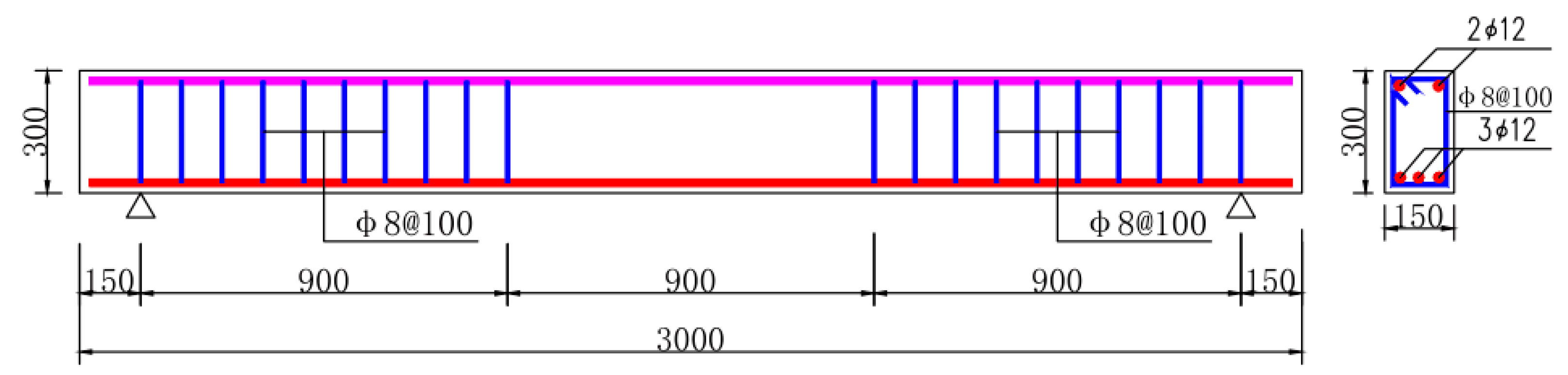
2.2. Preparation of Test Beams

Considering the prestress degrees of the CFRP sheets expressed by one-layer and two-layer CFRP sheets with two levels of prestress, four groups of test beams were prepared for testing. Additionally, two groups of reinforced concrete beams were required: one was used for determining the actual cracking loads of pure bending concrete of test beams under static loads, and the other was used for a reference of the flexural performance of reinforced concrete beams without strengthening by CFRP sheets under repeated loads. Therefore, 6 groups of test beams were needed in this experiment. With two beams under the same conditions as a group, twelve test beams were designed, as presented in Table 2. The width b = 150 mm and depth h = 300 mm for a rectangular section, and the length was 3.0 m for a span l0 = 2.7 m. Meanwhile, the pre-tension forces 20 kN and 30 kN of a layer of CFRP corresponded to 29.5% and 44.2% of tested ultimate tensile strength ffu = 4060 MPa. That is, the control tensioning stresses of CFRP sheets were 0.295ffu and 0.442ffu.
To ensure the beams strengthened with prestressed CFRP sheets failed in flexure as expected, rational longitudinal tensile reinforcement with enough stirrups was used to avoid the shear failure [3,4]. The reinforced concrete beams were designed with reinforcements of three longitudinal tensile steel bars with concrete cover of 25 mm and stirrups with spacing of 100 mm. The effective sectional depth h0 = 269 mm. The reinforcement ratio of longitudinal tensile steel bars was 0.84%, and the stirrups ratio was 0.67%. The designed bending capacity of reinforced concrete beams was 38.6 kN·m, while the designed shear capacity was 142.1 kN. Details of the beams are exhibited in Figure 1.

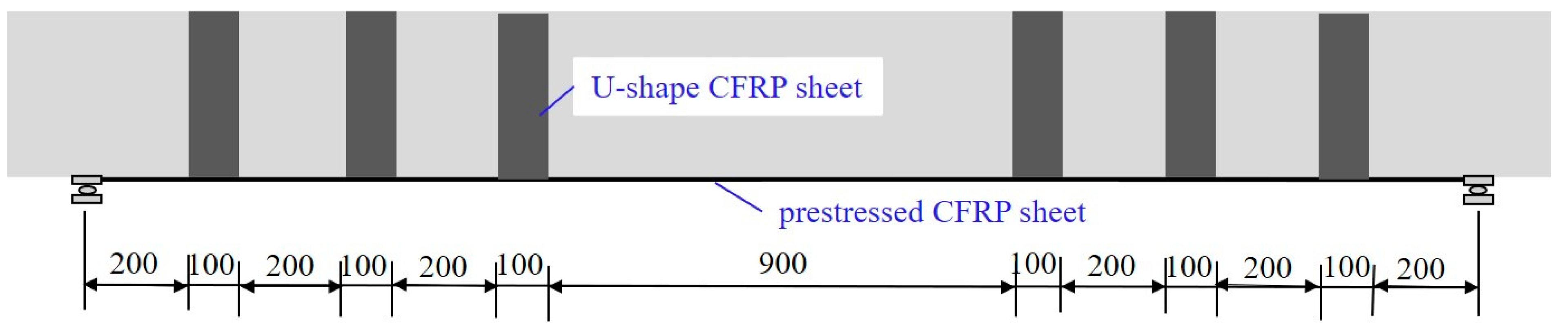
2.3. Pre-Crack Loading and Strengthening Method

The target pre-crack width was the limit of 0.20 mm for reinforced concrete beams in normal environment [40]. The cracks were made by four-point bending test [42,43]. The loads were multi-step with increments of 20% of the ultimate, except for the step that was 10% of the ultimate when the loads reached the cracking resistance. The crack width was detected by reading microscope during the loading process.
Two beams marked as JZL-0a/b were loaded until failure to obtain the reference data about the loads corresponding to the cracking resistance, the limit crack width of 0.20 mm, the yield of longitudinal tensile steel bars, the ultimate and the failure pattern.
The strengthening process of pre-cracked beams can be summarized as follows: (1) We polished the concrete surface that was bonded with CFRP sheets, made smooth arcs at the places with U-jacket CFRP sheets with grinding machine and cleaned them with acetone solution; (2) we smeared the adhesive on concrete surface with a roller; (3) we bonded one end of CFRP sheet on the bottom surface and fixed it with a U-jacket CFRP sheet; (4) we created tension with the CFRP sheet with a special prestress device that slips along the test beam and fixes the CFRP sheet at other end of test beam; (5) after the tensile strain of CFRP sheet remained constant, we smeared adhesive on CFRP sheet and bonded them on the bottom concrete surface; (6) we bonded the U-jackets of CFRP sheets at shear-span to fix the longitudinal CFRP sheets.
The tensile force was measured by the strain gauges pasted on the CFRP sheet and verified by the elongation of the CFRP sheet. After the strengthening work, the beams were cured indoors for 3 days to ensure the adhesive solidification. Figure 2 shows the CFRP sheets bonded on test beams.

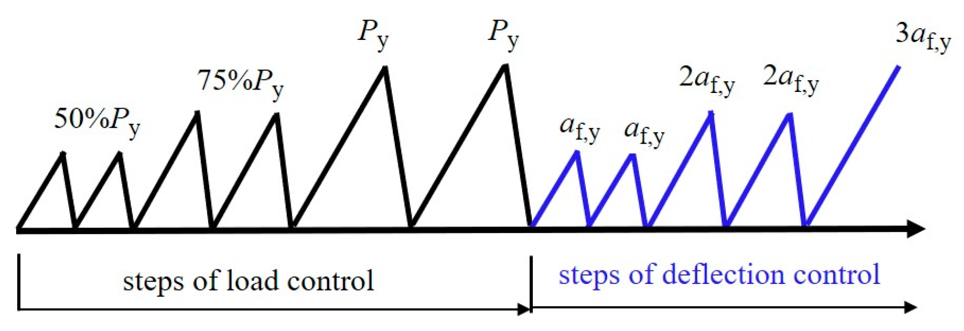
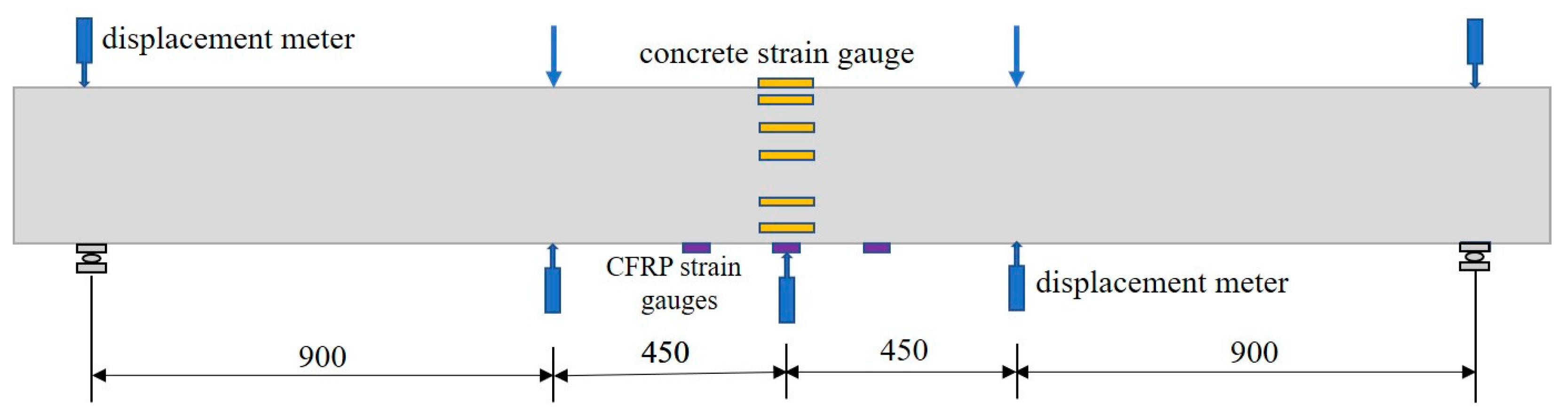
2.4. Repeated Loading Method and Instruments

As exhibited in Figure 3, test beam was simply supported on supports with steel rollers, and two hydraulic jacks on top surface of test beam at the one-third points were used to exert the repeated load. The hydraulic jacks were hung by steel frames, which were fixed on the steel foundation. The repeated load of each step was measured by the load meters linked to the hydraulic jacks, while it was verified by the meter of a hydraulic oil pump, which provided oil pressure to the parallelly connected jacks. The load meters were automatically recorded by a DH3818-type data acquisition system produced by Shanghai Donghua Test Machine Co., Ltd. (Shanghai, China).
Figure 4 shows the repeated load history of this study; each step is in a static manner [44]. The yield load (Py) and the yield deflection (af,y) at mid-span are a load and a mid-span deflection that correspond to the yield of the longitudinal tensile steel bars. Before the yield of longitudinal steel bars, the load was exerted in steps at 50%, 75% and 100% of the yield load Py; each step was repeated two times. During the process of each step, the load was divided several times to simulate a continuously increased = decreased load subjected by the test beam. After the yield of longitudinal steel bars, the load was controlled in steps by the deflection, which increased at intervals by multiples of the yield deflection af,y; each step was also repeated two times.
Before casting concrete of test beams, the strain gauges with size of 1 mm × 1 mm were bonded on the longitudinal tensile steel bars at mid-span section and covered by epoxy resin with a bed of gauze. The wires of strain gauges were guided outside of concrete with enough length to be linked to the strain meter. In addition, the strain of longitudinal CFRP sheet was measured by three gauges that were pasted on surface of CFRP along the length direction, and the concrete strain changed at mid-span section was measured by three strain gauges pasted on top surface and five strain gauges pasted along depth direction on side surface of mid-span section, as presented in Figure 5. The deflection of test beam was measured by five displacement meters placed on supports, mid-span and loading sections. All test data were recorded by the data acquisition system. The size of strain gauges pasted on concrete was 100 mm × 3 mm, and that which was pasted on CFRP was 5 mm × 3 mm. The crack width was detected by a reading microscope.

3. Test Results and Analyses

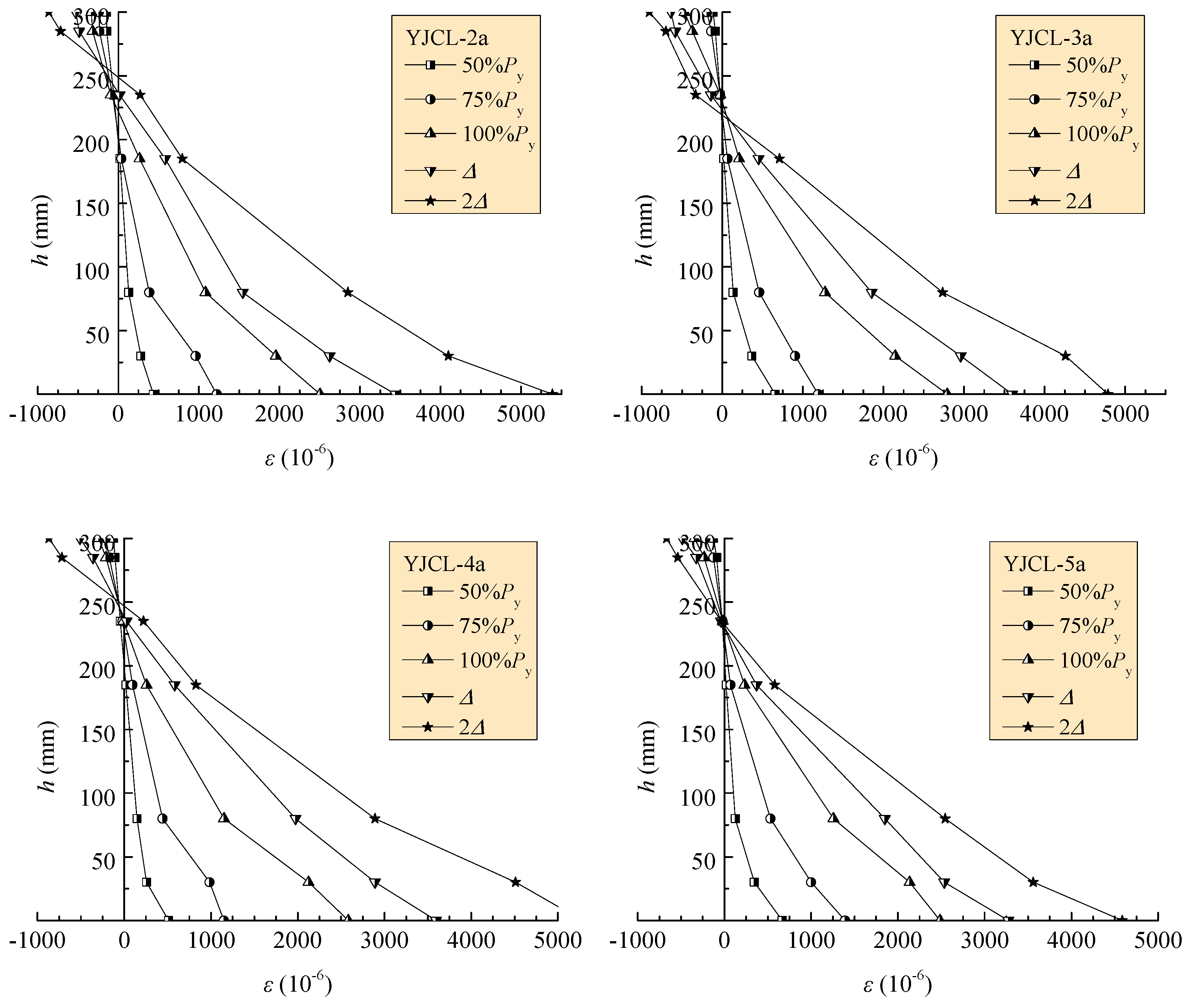
3.1. Concrete Strain along Depth of Mid-Span Section

Figure 6 presents the concrete strains along the depth of the mid-span section on part of the test beams under the peak repeated load at the second repetition of each loading step. The concrete strain at the key loading steps, including the decompression of the bottom surface, the yield of longitudinal tensile steel bars and the ultimate state, can be determined from the figures. Similar to that of reinforced concrete beams under static and repeated loads, the concrete strain along the depth of the mid-span section of the strengthened reinforced concrete beams still maintained a linear variation close to a plane. Therefore, the assumption of plane section is also adaptable to reinforced concrete beams strengthened with prestressed CFRP sheets.

3.2. Crack Distribution and Development

The cracks distributed on test beams are presented in Figure 7. Beams JZCL-1a/b initially cracked at a load of 12.5 kN with a crack width of 0.03 mm and a height of about 130 mm. The number of cracks increased, while the widths increased on the beams during the first two steps of repeated loads. Beams JZCL-1a and JZCL-1b, respectively, reached the yield at loads of 37.0 kN and 41.7 kN. At this point, the beams underwent a large deformation with the extension and opening of cracks and formed main cracks with large widths and heights. Under the repeated load controlled by deformation, the widths of the cracks continuously increased. The compression concrete crushed at 44.8 kN and 49.6 kN, respectively, for beams JZCL-1a and JZCL-1b underwent the 3af,y repetition.
Beams YJCL-2a/b initially cracked with a width of 0.02–0.03 mm and a height of about 90 mm at loads of 9 kN and 11 kN, respectively. When the load reached 39.6 kN, several microcracks along prestressed CFRP sheets appeared, along with slight crackles of transversal wires. When the load reached 55.5 kN, the beams reached the yield with many more cracks even on the shear-span. After the repetition was controlled by deformation, the deflection increased with the extension of cracks.
Beams YJCL-3a/b initially cracked with a width of 0.05 mm and a height of about 100 mm at loads of 12.5 kN and 13.5 kN, respectively. Under the repeated loads, the number of cracks increased with slight extension and opening. The CFRP sheets presented a slight crackle at the load of 63.4 kN, and some wires of the outside layer broke at the loads of 67.4 kN and 75.5 kN, respectively, for beams YJCL-3a and YJCL-3b. After the repetition was controlled by deformation, the crackling of the CFRP sheets continuously sounded, while the cracks slightly extended.
Beams YJCL-4a/b initially cracked with a width of 0.02 mm and height of about 70–140 mm at a load of 9 kN. The cracks extended obviously with a crackle of the bond matrix under repeated loads of 47.5 kN. The longitudinal tensile steel bars yielded respectively at the loads of 63.4 kN and 59.5 kN. After that, new cracks appeared on the shear-span and extended rapidly.
Beams YJCL-5a/b initially cracked with a width of 0.02 mm and a height of about 70–120 mm at load of 13.5 kN. Beam YJCL-5a showed a crackle of the CFRP sheets at a load of 39.6 kN, and the cracks extended rapidly afterward; the yield load reached 77.3 kN. Beam YJCL-5b had a little change in the cracks under the repeated load before the yield at a load of 71.4 kN. Continuously, the cracks extended rapidly in both the pure bending segment and the shear-span.
Generally, the cracks in the pure bending segment of test beams basically elongated vertically along the depth direction and forked at the end part. The inclined cracks in the shear-span segment extended at a slant while confined by the U-jacket CFRP sheet. According to the statistical results of the cracks summarized in Table 3, the number of cracks increased while the spacing of cracks decreased with the increase of the prestressing of CFRP sheets. This minimized the maximum crack width of the strengthened beams at the serviceability limit state due to the confinement of the prestressed CFRP sheets to the extension and opening of cracks. Meanwhile, the crack width at the ultimate state presented a downward tendency with the increased prestressing of the CFRP sheets.

3.3. Mid-Span Deflection

The skeleton load vs. mid-span deflection curves of test beams are presented in Figure 8, while those corresponding to the complete load vs. mid-span deflection curves of test beams are drawn in Figure 9. Obviously, beams JZCL-1a/b, which were not strengthened by CFRP sheets, presented a larger deformability after the yield of longitudinal tensile steel bars, which could undergo the 2af,y repetition. Comparatively, beams YJCL-2a/b, which were strengthened by one layer of prestressed CFRP sheets with a tensioning force of 20 kN, could withstand the 2af,y repetition, while other beams all failed during the 2af,y repetition.
The skeleton curves contain the ascending portion without a tendency of descending. This is similar to that of the reinforced concrete beams strengthened with prestressed CFRP sheets under static loads [45,46]. With the increase in the prestress degree of CFRP sheets, the flexural stiffness of test beams in the sequence of YJCL-2a/b, YJCL-4a/b, YJCL-3a/b and YJCL-5a/b increased in portions not only before but after the yield of the longitudinal tensile steel bars. This indicates that the entirety of the flexural segment of the test beams was ensured due to the confinement effect of prestressed CFRP sheets on the development of cracks under repeated loads. As a result, the normal serviceability was improved due to a small deflection that happened on the beams under the same loads. Meanwhile, the bearing capacity of test beams was improved with relatively small deflection due to the strengthening of prestressed CFRP sheets. Compared to the greater deflection that happened on the beams without strengthening, the CFRP-strengthened beams had almost similar deflection at the ultimate state due to the failure that came from the fracturing of the CFRP sheets.

3.4. Failure Patterns

The failure patterns of test beams are recorded in photos in Figure 10. Beams JZCL-1a/b without strengthening failed with crushed compressive concrete after the yield of longitudinal tensile steel bars. This is a normal failure pattern with sufficient ductility [47]. Comparatively, beams YJCL-2a/b and YJCL-4a/b, which were strengthened by using one layer of prestressed CFRP sheets with tensioning forces of 20 kN and 30 kN, failed, with the CFRP sheets breaking after the yield of longitudinal tensile steel bars. Beams YJCL-3a/b and YJCL-5a/b, which were strengthened by using two layers of prestressed CFRP sheets with tensioning forces of 40 kN and 60 kN, failed, with the CFRP sheets breaking into filaments and peeling off the concrete, while part of the tensile concrete bonded to the CFRP sheets in the pure bending segment and longitudinally cracked due to the drawing of fractured CFRP sheets, and the U-jacket CFRP sheets near the loading sections peeled off or were partially broken. This shows that a reliable bond between the CFRP sheets and concrete is a premise of synergistic action [48]. Strengthened by a layer of CFRP sheets with control tensioning stresses of 0.295ffu and 0.442ffu, the load capacity of test beams at the yield of longitudinal tensile steel bars increased by 41.0% and 56.2%, while the ultimate load capacity increased by 41.9% and 43.8%. Strengthened by two layers of CFRP sheets with control tensioning stresses of 0.295ffu and 0.442ffu, the load capacity of test beams at the yield of longitudinal tensile steel bars increased by 81.4% and 88.8%, while the ultimate load capacity increased by 56.5% and 74.8%.
Table 4 lists the maximum strains of longitudinal tensile steel bars, CFRP sheets and the compressive concrete of test beams at the states of the decompression of bottom surface concrete, the yield of longitudinal tensile steel bars and the ultimate loads. The strains of CFRP sheets are synergetic with those of bottom surface concrete in the repeated loading process until the CFRP sheet peeled off the concrete. With the increase in the prestress of the CFRP sheets, the ultimate strains of longitudinal tensile steel bars became larger. This means that a higher prestress of CFRP sheets led to a greater pre-compressed strain of longitudinal tensile steel bars. Meanwhile, a lower tensile strain of CFRP sheets accompanied by a higher prestress at the broken state, due to the larger strain of CFRP sheets, occurred under the higher pretension force. If the prestress loss of CFRP sheets was about 10% tension stress, the effective pretension strains at 20 kN and 30 kN were 4355 με and 6532 με, respectively. However, the broken strain of CFRP sheets only reached 9547–12,542 με, which was about 57–75% of the ultimate strain 16,776 με. This indicates that the CFRP sheets bonded on test beams could not reach the ultimate strength due to the breaking of some wires with uneven tensioning.
Due to the precompression of longitudinal steel bars under the tensioning of prestressed CFRP sheets, the longitudinal steel tensile bars were still in compression when the concrete was decompressed at bottom surface of the bending section. Due to the compression zone of test beams under repeated load being the tensile zone under the prestressed CFRP sheets, the compression of concrete was postponed by the pre-tensioning of prestressed CFRP sheets. This led to the compressive strain of concrete at the failure state not being able to reach the ultimate, and no crushing of compressive concrete took place.

4. Prediction of Bending Performances

Based on the stress process of reinforced concrete beams strengthened by prestressed CFRP sheets, prediction formulas are proposed according to the design principles of prestressed concrete beams [3,40]. To put it simply, the stresses of CFRP sheets and longitudinal tensile steel bars are positive in tension, and that of concrete is positive in compression.

4.1. Assumptions for Predicting Flexural Performance

The assumptions for predicting flexural performance are summarized as follows:
(1)
The strain along normal-section depth fits for the plane section;
(2)
The constitutive model of concrete can be expressed as:
σ c = 2 [ ( ε c ε 0 ) ( ε c ε 0 ) 2 ] f c   ( ε c < ε 0 )
σ c = f c   ( ε 0 < ε c ε cu )
where ε0 = 0.002, εcu = 0.0033.
(3)
No bond slip exists between longitudinal tensile steel bars and concrete. The constitutive model of steel bars can be expressed as:
σ s = E s ε s ( ε s ε y )
σ s = f y ( ε s > ε y )
(4)
No bond slip exists along the interface between prestressed CFRP sheets and concrete. The linear constitutive model of CFRP sheets can be used as:
σ f = E f ε f   ( ε f ε fu )
(5)
The flexural stiffness is the same along the span of beam, and the depths of prestressed CFRP sheets can be neglected.
(6)
The residual strains of concrete and steel bars are neglected due to the pre-crack width being controlled within the limit.

4.2. Prestress Loss of CFRP Sheet

The control stress for the pre-tensioning of CFRP sheets can be calculated as:
σ f , con = N f / E f A f
The prestress loss of CFRP sheets due to compression of anchorage locked on the ends of reinforced concrete beams can be calculated as:
σ l 1 = Δ L f σ f , con
The prestress loss due to the relaxation of CFRP sheets and the long-term deformation of RC beams can be calculated as [29]:
σ l 2 = 2 % σ f , con
The prestress loss due to the shrinkage and creep of concrete can be calculated referencing the prestressed concrete with steel reinforcement [40]:
σ l 3 = 35 + 280 σ pc / f cu 1 + 15 ρ
σ pc = ( σ f , con σ l 1 σ l 2 ) A f A 0 + ( σ f , con σ l 1 σ l 2 ) A f ( h y 0 ) 2 I 0
I 0 = ( 0.0833 + 0.1 α Es ρ ) b h 3
y 0 = ( 0.5 + 0.42 α Es ρ ) h
Therefore, the effective prestress of CFRP sheets can be calculated as:
σ pf = σ f , con σ l 1 σ l 2 σ l 3

4.3. Initial Prestress of Concrete and Steel Bars

The prestress of concrete on the top and bottom surfaces of reinforced concrete beams can be calculated as:
σ pc , T = σ pf A f A 0 σ pf A f ( h y 0 ) y 0 I 0
σ pc , B = σ pf A f A 0 + σ pf A f ( h y 0 ) 2 I 0
The prestress of the longitudinal tensile steel bars of reinforced concrete beams can be calculated as:
σ ps = α Es σ pf A f A 0 α Es σ pf A f ( h y 0 ) ( h 0 y 0 ) I 0

4.4. Stress When Prestress Disappeared at the Bottom Concrete Surface

With the increase in repeated loads, the pre-compression of concrete at the bottom surface of RC beams will be reduced. The prestress disappears when the tensile stress produced by the load reaches the pre-compressive stress, and the corresponding bending moment on the cross-section of RC beam can be obtained with the following formula:
        M 0 = σ pc , B I 0 / ( h y 0 )
With the assumption that no bond slip exists along the interface between CFRP sheets and concrete, the changes in strain are the same between CFRP sheets and concrete at the bottom surface. Therefore, the stress of CFRP sheets is:
        σ 0 f = σ pf + α Ef σ pc , B
The stress of longitudinal tensile steel bars of RC beams can be calculated as:
σ 0 s = σ ps + α Es M 0 ( h 0 y 0 ) I 0
In this study, due to the compression of the anchorage only taking place at the tensioning end, the compression of the anchorage locked on the reinforced concrete beams Δ = 2 mm. The length of the CFRP sheets Lf = 2.3 m, which was determined by the total length 2.7 m minus the fixed ends of 200 mm. Table 5 summarizes the control prestress, prestress losses and effective prestress of the CFRP sheets, the initial prestresses of concrete and steel bars and the stresses of CFRP sheets and steel bars at the prestress disappearance at the bottom concrete surface.

4.5. Flexural Stiffness

Due to the reinforced concrete beams being loaded with cracks before strengthening, if the prestress of concrete disappeared at the bottom surface of the strengthened beams, the flexural behavior is similar to that of conventional reinforced concrete beams after concrete cracking. Therefore, the cracking moment corresponds to the prestress disappearance at the bottom surface of strengthened beams. Similar to the prestressed concrete beams [40,48], the flexural stiffness can be calculated at two stages.
When MM0,
B 0 = 0.85 E c I 0
When M > M0,
B = 0.85 E c I 0 M 0 M + ( 1 M 0 M ) ( ( 1 + 0.21 α Es ρ ) 0.7 )
Based on the principle of equivalent flexural stiffness for reinforced concrete beams, the mid-span deflection can be calculated as:
a f = 0.1132 ( M / B M 0 / B 0 ) l 0 2
With the above formulas for calculating the mid-span deflection at normal serviceability state, the predicted results agree well with the tested ones.

4.6. Stress at the Yield of Longitudinal Steel Bars

With the assumption of the plane section, the strains of concrete at the top surface and the longitudinal tensile steel bars are calculated as:
ε c , y = 0.002 σ pc , T E c
ε s , y = f y σ ps E s

4.7. Flexural Bearing Capacity

Considering that the prestressed CFRP sheets broke without reaching the ultimate tensile strain, the flexural bearing capacity of the strengthened beams under repeated loads can be conservatively predicted at the yield of longitudinal tensile steel bars. The compression zone of concrete can be simplified as a linear stress distribution along the sectional depth, and the length of internal force arm is taken respectively as 0.92h0 for calculating the bearing capacity at the yield of longitudinal tensile steel bars and that at the ultimate state [40,48]. Based on this experimental study, the tensile stress of CFRP sheets at the ultimate state of strengthened beams can be taken as 0.65ffu. Therefore, based on the fore and moment equilibrium conditions on the bending section, the flexural bearing capacity of the strengthened beams at the yield of longitudinal tensile steel bars and that at the ultimate state can be predicted as follows:
M y = 0.92 f y A s h 0 + A f ( σ 0 f + ( f y σ 0 s ) ( 1 + 2 a s / h 0 ) ) ( 0.92 h 0 + a s )
M u = 0.92 f y A s h 0 + 0.65 f fu A f ( 0.92 h 0 + a s )
The prediction results of the flexural capacity of the test strengthened beams are presented in Table 6. Good prediction can be performed with the fitness of test results.

4.8. Ductility

Due to the yield of test beams being able to be determined by experiments in this study, the ductility of test beams is represented by the deflection ductility facto (μ). This is a ratio of the mid-span deflection at the ultimate state to that at the yield state of test beams. The results are presented in Table 7. The ductility of test beams without strengthening by CFRP sheets was ideal, while that of test beams strengthened with prestressed CFRP sheets obviously reduced by 54.9% to 186%. This is due to the greater brittleness of CFRP sheets impregnated with epoxy resin. The breaking of CFRP sheets took place after the beams reached the yield state, with most of them accompanied by peeling off from the concrete and rapidly reaching the ultimate. The ductility was reduced with the increase in the layers of CFRP sheets under the conditions of the same prestress and were reduced with the prestress increase in the case of the same layers of CFRP sheets. Therefore, the sharp reduction in the ductility of beams strengthened with prestressed CFRP sheets needs to be addressed.

5. Conclusions

Based on this experimental study of cracked reinforced concrete beams strengthened with prestressed CFRP sheets under repeated loads, conclusions can be drawn as follows:
(1)
The assumption of the plane section is adaptable for reinforced concrete beams with prestressed CFRP sheets under repeated load. This provides a foundation for building the calculation methods for the bending behaviors of strengthened beams.
(2)
Attributed to the precompression of concrete in the tensile zone of reinforced concrete beams under repeated loads, the spacing and widths of cracks decreased with the increased prestress of CFRP sheets. The flexural stiffness increased correspondingly to reduce the mid-span deflection. The strengthened beams with the highest prestress degree of CFRP sheets could limit the maximum crack width to within 0.2 mm, while others could limit the maximum crack width to within 0.3 mm. Therefore, the normal serviceability of the strengthened beams can be improved with small crack width and deflection.
(3)
The strengthened beams could reach a higher bearing capacity with the increase in the prestress of CFRP sheets. With the control tensioning stresses of CFRP sheets at 0.295ffu and 0.442ffu, the strengthened beams with a layer of CFRP sheets presented an increased load capacity at the yield of longitudinal tensile steel bars by 41.0% and 56.2%, while the ultimate load capacity increased by 41.9% and 43.8%; the strengthened beams with two layers of CFRP sheets had an increased load capacity at the yield of longitudinal tensile steel bars by 81.4% and 88.8%, while the ultimate load capacity increased by 56.5% and 74.8%. However, the reduction in ductility represented by the ratio of mid-span deflection at the ultimate to that at the yield of longitudinal tensile steel bars needs to be addressed.
(4)
The ideal strengthening effect depends on the reliable bonding of CFRP sheets to concrete. Measurement should be further studied to prevent the CFRP sheets from peeling off of bonded concrete, and the breaking of CFRP sheets resulted from the damage of cracked concrete along longitudinal tensile steel bars.

Author Contributions

Conceptualization and methodology, F.L. and Y.W.; validation, H.W., C.L. and Q.M.; formal analysis and investigation, writing—original draft preparation, H.W., S.S. and C.L.; writing—review and editing, Y.W. and Q.M.; supervision and funding acquisition, F.L. All authors have read and agreed to the published version of the manuscript.

Funding

This research was funded by the CSCEC Technology Research and Development Project, China (CSCEC-2021-Z-24), and Special Joint Research Project of Zhengzhou City and NCWU, China (2021013).

Data Availability Statement

Data are available with the first author and can be shared with anyone upon reasonable request.

Conflicts of Interest

The authors declare no conflict of interest.

Glossary

Nfthe pre-tensioning force of CFRP sheets;
Mthe moment on the pure bending segment of RC beams under repeated loads;
M0the bending moment produced by repeated load when the prestress of concrete disappeared at the bottom surface;
Mythe yield moment of the beams at the yield of longitudinal tensile steel bars;
Muthe ultimate moment of the beams at the ultimate state;
bthe sectional width of RC beams;
bfthe width of CFRP sheets;
hthe sectional depth of RC beams;
h0the effective sectional depth of RC beams;
l0the span of RC beams;
lmthe average spacing of cracks on the side surface at central height of the longitudinal tensile steel bars of RC beams;
tfthe depth of CFRP sheets;
y0the distance from central axis to top section-edge of the transferred section of RC beams;
Asthe sectional area of longitudinal tensile steel bars;
Afthe sectional area of CFRP sheets;
Bthe flexural stiffness of RC beams strengthened by prestressed CFRP sheets;
I0the inertia moment of the transferred section of RC beam;
Lfthe length of CFRP sheets;
fcthe axial compressive strength of concrete;
fythe yield strength of steel bars;
ffuthe ultimate tensile strength of CFRP sheets;
σcthe stress of concrete;
σsthe stress of longitudinal tensile steel bars;
σfthe stress of CFRP sheets;
σf,conthe control stress of pre-tensioning for CFRP sheets;
σl1the prestress loss of CFRP sheets due to the compression of the anchorage locked on RC beams;
σl2the prestress loss due to the relaxation of CFRP sheets;
σl3the prestress loss due to the shrinkage and creep of concrete;
σpcthe prestress of concrete after the prestress loss at the first stage;
σpfthe effective prestress of CFRP sheets after the whole prestress loss;
σpc,Tthe prestress at the top edge of cross-section of RC beam;
σpc,Bthe prestress at the bottom edge of cross-section of RC beam;
σpsthe prestress of longitudinal tensile steel bars;
σ0fthe stress of CFRP sheets when the prestress of concrete disappeared at the bottom edge;
σ0sthe stress of longitudinal steel bars when prestress of concrete disappeared at the bottom edge;
εcthe strain of concrete;
εsthe strain of longitudinal steel bars;
εfthe strain of CFRP sheets;
εf,ythe strain of CFRP sheets corresponding to the yield of longitudinal tensile steel bars;
εf,maxthe maximum strain of CFRP sheets at fracture;
Ecthe modulus of elasticity of concrete;
Esthe modulus of elasticity of steel bars;
Efthe modulus of elasticity of CFRP sheet;
αEsthe elastic modulus ratio between steel bars and concrete;
αEfthe elastic modulus ratio between CFRP sheet and concrete;
afthe mid-span deflection;
afythe mid-span deflection at the yield state of RC beam;
afuthe mid-span deflection at the ultimate state of RC beam;
ρthe ratio of longitudinal tensile steel bars;
Δthe compression value of anchorage locked on RC beam;
μthe ductility factor.
wmaxthe maximum crack width on the side surface at central height of the longitudinal tensile steel bars of RC beam.

References

  1. GB 55021-2021; General Code for Appraisal and Strengthening of Existing Buildings. China Building Industry Press: Beijing, China, 2021.
  2. GB 55022-2021; General Code for Maintenance and Renovation of Existing Buildings. China Building Industry Press: Beijing, China, 2021.
  3. GB 50367-2013; Code for Design of Strengthening Concrete Structures. China Building Industry Press: Beijing, China, 2013.
  4. GB/T 21490-2008; Carbon Fiber Sheet for Strengthening and Restoring Structures. China Building Industry Press: Beijing, China, 2008.
  5. GB/T 26745-2011; Basalt Fiber Composites for Strengthening and Restoring Structures. China Building Industry Press: Beijing, China, 2011.
  6. JG/T 284-2019; Glass Fiber Sheet for Strengthening and Restoring Structures. China Building Industry Press: Beijing, China, 2019.
  7. Norris, T.; Saadatmanesh, H.; Ehsani, M.R. Shear and flexural of R/C beams with carbon sheets. J. Struct. Eng. 1997, 123, 903–910. [Google Scholar] [CrossRef]
  8. Li, A.; Assih, J.; Delmas, Y. Shear strengthening of RC beams with externally bonded CFRP sheets. J. Struct. Eng. 2001, 127, 374–380. [Google Scholar] [CrossRef]
  9. Liao, S.; Lu, Y.; Chen, D. Test on seismic behavior of reinforced concrete beams composite rehabilitation with bonded carbon fiber reinforced polymer and steel plate. J. Civ. Architect. Environ. Eng. 2010, 32, 14–21. [Google Scholar]
  10. Al-Rousan, R.; Al-Saraireh, S. Impact of anchored holes technique on behavior of reinforced concrete beams strengthened with different CFRP sheet lengths and widths. Case Stud. Construct. Mater. 2020, 13, e00405. [Google Scholar] [CrossRef]
  11. Gribniak, V.; Tamulenas, V.; Ng, P.-L.; Arnautov, A.K.; Gudonis, E.; Misiunaite, I. Mechanical behavior of steel fiber-reinforced concrete beams bonded with external carbon fiber sheets. Materials 2017, 10, 666. [Google Scholar] [CrossRef]
  12. Lorenzis, L.; Teng, J. Near-surface mounted FRP reinforcement: An emerging technique for strengthening structures. Compos. Part B Eng. 2007, 38, 119–143. [Google Scholar] [CrossRef]
  13. Zhang, S.; Ke, Y.; Chen, E.; Biscaia, H.; Li, W. Effect of load distribution on the behaviour of RC beams strengthened in flexure with Near-Surface Mounted (NSM) FRP. Compos. Struct. 2022, 279, 114782. [Google Scholar] [CrossRef]
  14. Al-zúbi, H.; Abdel-Jaber, M.; Katkhuda, H. Flexural strengthening of reinforced concrete beams with variable compressive strength using near-surface mounted carbon-fiber-reinforced polymer strips [NSM-CFRP]. Fibers 2022, 10, 86. [Google Scholar] [CrossRef]
  15. Ding, J.; Cheng, L.; Chen, X.; Chen, C.; Liu, K. A review on ultra-high cycle fatigue of CFRP. Compos. Struct. 2021, 256, 113058. [Google Scholar] [CrossRef]
  16. Wu, J.; Zhu, Y.; Li, C. Experimental investigation of fatigue capacity of bending-anchored CFRP cables. Polymers 2023, 15, 2483. [Google Scholar] [CrossRef]
  17. Triantafillou, T.C.; Deskovic, N.; Deuring, M. Strengthening of concrete structures with prestressed fiber reinforced plastic sheets. ACI Struct. J. 1992, 89, 235–244. [Google Scholar]
  18. Char, M.; Saadatmanesh, H.; Ehsnai, M.R. Concrete girders externally prestressed with composite plates. PCI J. 1994, 39, 40–51. [Google Scholar]
  19. Shang, S.; Peng, H.; Tong, H.; Wei, D.; Zeng, L. Study on bending property of concrete flexural members strengthened by prestress CFRP sheet. J. Build. Struct. 2003, 24, 24–30. [Google Scholar]
  20. Jiang, S.; Hou, J.; He, Y. Experimental study on flexural behavior of RC beams strengthened with prestressed CFRP sheets. J. Build. Struct. 2008, 10–14. [Google Scholar]
  21. Pan, L.; Chen, S.; Zhao, S.; Li, C. Experimental study of cyclic loading behaviors of reinforced concrete beams strengthening with CFRP sheets. Appl. Mechan. Mater. 2012, 201–202, 483–486. [Google Scholar] [CrossRef]
  22. Heffernan, P.; Wight, R.; Erki, M. Fatigue behaviour of concrete slabs strengthened with prestressed CFRP sheets. In Proceedings of the 2nd International Conference on Durability of Fiber Reinforced Polymer Composites for Construction, Montreal, QC, Canada, 29–31 May 2002; pp. 465–474. [Google Scholar]
  23. Gao, Z.; Wang, W.; Huang, H. Calculation of flexural capacity of RC beams strengthened with prestressed CFRP sheets. J. Southeast Univ. Nat. Sci. Ed. 2013, 43, 195–202. [Google Scholar]
  24. Cao, Q.; Zhou, J.; Wu, Z.; Ma, Z. Flexural behavior of prestressed CFRP reinforced concrete beams by two different tensioning methods. Eng. Struct. 2019, 189, 411–422. [Google Scholar] [CrossRef]
  25. Piątek, B.; Siwowski, T. Experimental study on flexural behaviour of reinforced concrete beams strengthened with passive and active CFRP strips using a novel anchorage system. Arch. Civ. Mechan. Eng. 2022, 22, 45. [Google Scholar] [CrossRef]
  26. Wang, Z.; Fan, H.; Liu, Z.; Zhao, S. Experimental study on anchoring performance of flat anchorage with circular tooth for prestressed CFRP plate. Sci. Technol. Eng. 2017, 17, 279–283. [Google Scholar]
  27. Liu, G.; Li, B.; Bao, J.; Cheng, S.; Meng, Q.; Zhao, S. Case study on prestressed CFRP plates applied for strengthening hollow-section beam removed from an old bridge. Polymers 2023, 15, 549. [Google Scholar] [CrossRef]
  28. Xian, G.; Guo, R.; Li, C.; Wang, Y. Mechanical performance evolution and life prediction of prestressed CFRP plate exposed to hygrothermal and freeze-thaw environments. Compos. Struct. 2022, 293, 115719. [Google Scholar] [CrossRef]
  29. Li, X.; Deng, J.; Wang, Y.; Xie, Y.; Liu, T.; Rashid, K. RC beams strengthened by prestressed CFRP plate subjected to sustained loading and continuous wetting condition: Time-dependent prestress loss. Constr. Build. Mater. 2021, 275, 122187. [Google Scholar] [CrossRef]
  30. Deng, J.; Li, X.; Wang, Y.; Xie, Y.; Huang, C. RC beams strengthened by prestressed CFRP plate subjected to sustained loading and continuous wetting condition: Flexural behaviour. Constr. Build. Mater. 2021, 311, 125290. [Google Scholar] [CrossRef]
  31. Lu, Z.; Li, J.; Xie, J.; Huang, P.; Xue, L. Durability of flexurally strengthened RC beams with prestressed CFRP sheet under wet–dry cycling in a chloride-containing environment. Compos. Struct. 2021, 255, 112869. [Google Scholar] [CrossRef]
  32. Wei, M.; Xie, J.; Li, J.; Xiang, C.; Huang, P.; Liu, F. Effect of the chloride environmental exposure on the flexural performance of strengthened RC beams with self-anchored prestressed CFRP plates. Eng. Struct. 2021, 231, 111718. [Google Scholar] [CrossRef]
  33. Xie, J.; Li, J.; Lu, Z.; Liu, D.; Huang, P. Effects of pre-existing damage and cyclic overloading on the flexural behaviour of RC beams strengthened with prestressed CFRP plates. Eng. Struct. 2021, 247, 113078. [Google Scholar] [CrossRef]
  34. JGJ 55-2011; Specification for Mix Proportion Design of Ordinary Concrete. China Building Industry Press: Beijing, China, 2011.
  35. GB 175-2007; Common Portland Cement. China Standard Press: Beijing, China, 2007.
  36. JGJ 52-2006; Standard for Technical Requirements and Test Method of Sand and Crushed Stone (or Gravel) for Ordinary Concrete. China Building Industry Press: Beijing, China, 2006.
  37. GB 50119-2013; Code for Concrete Admixture Application. China Building Industry Press: Beijing, China, 2014.
  38. Zhao, M.; Ding, X.; Li, J.; Law, D. Numerical analysis of mix proportion of self-compacting concrete compared to ordinary concrete. Key Eng. Mater. 2018, 789, 69–75. [Google Scholar] [CrossRef]
  39. GB/T 50081-2019; Standard for Test Method of Mechanical Properties on Ordinary Concrete. China Building Industry Press: Beijing, China, 2019.
  40. GB 50010-2010; Code for Design of Concrete Structures. China Building Industry Press: Beijing, China, 2010.
  41. GB/T 228.1-2010; Metallic Materials—Tensile testing—Part 1: Method of Test at Room Temperature. China Standard Press: Beijing, China, 2011.
  42. Li, C.; Liu, T.; Fu, H.; Zhang, X.; Yang, Y.; Zhao, S. Test and evaluation of the flexural properties of reinforced concrete beams with 100% recycled coarse aggregate and manufactured sand. Buildings 2021, 11, 420. [Google Scholar] [CrossRef]
  43. Li, C.; Zhao, M.; Zhang, X.; Li, J.; Li, X.; Zhao, M. Effect of steel fiber content on shear performance of reinforced expanded-shale lightweight concrete beams with stirrups. Materials 2021, 14, 1107. [Google Scholar] [CrossRef]
  44. JGJ/T 101-2015. Specification for Seismic Test of Buildings. China Building Industry Press: Beijing, China, 2015.
  45. Zhao, W.; Li, X.; Zhao, S. Experimental study on loading behaviors of reinforced concrete beams strengthening with prestressed CFRP. Yellow River 2012, 34, 136–138. [Google Scholar]
  46. Slaitas, J.; Valivonis, J. Concrete cracking and deflection analysis of RC beams strengthened with prestressed FRP reinforcements under external load action. Compos. Struct. 2021, 255, 113036. [Google Scholar] [CrossRef]
  47. Zhao, S. Design Principle of Concrete Structures, 2nd ed.; Tongji University Press: Shanghai, China, 2013. [Google Scholar]
  48. Wang, X.; Zhao, G.; Li, K.; Li, M. Effect of damage parameter variation on bond characteristics of CFRP-sheets bonded to concrete beams. Constr. Build. Mater. 2018, 185, 184–192. [Google Scholar] [CrossRef]
Figure 1. Geometry and reinforcement details of reinforced concrete beam (unit: mm).
Buildings 13 02115 g001
Figure 2. Test beams strengthened by CFRP sheets.
Buildings 13 02115 g002
Figure 3. Repeated loading devices for test beams.
Buildings 13 02115 g003
Figure 4. Steps of repeated loads.
Buildings 13 02115 g004
Figure 5. Arrangement of the displacement meters and the strain gauges pasted on concrete and CFRP sheets.
Buildings 13 02115 g005
Figure 6. Concrete strain along depth of mid-span section on part of test beams.
Buildings 13 02115 g006
Figure 7. The crack distributed on test beams.
Buildings 13 02115 g007
Figure 8. Skeleton load mid-span deflection curves of test beams.
Buildings 13 02115 g008
Figure 9. The complete load mid-span deflection curves of test beams.
Buildings 13 02115 g009
Figure 10. Failure patterns on bending segment of test beams.
Buildings 13 02115 g010
Table 1. Properties of adhesive for CFRP sheets.
Tensile Strength (MPa)Flexural Strength (MPa)Compressive Strength (MPa)Shear Strength (MPa)Tensile Modulus of Elasticity (GPa)Elongation (%)Bond Strength to Concrete
(MPa)
Non-Volatile Matter Content (%)
51.575.489.618.331.01.703.6099.5
Table 2. Tested concrete strengths and strengthening parameters of test beams.
Beam No.fcu
(MPa)
ft
(MPa)
Layer of CFRPPre-Tension Force (kN)Loading Method
JZL-0a60.13.7100Statistic to determine the cracking load
JZL-0b60.13.7100Statistic to determine the cracking load
JZCL-1a60.13.7100Repeated as a reference
JZCL-1b56.73.6400Repeated as a reference
YJCL-2a56.73.64120Repeated
YJCL-2b56.73.64120Repeated
YJCL-3a59.63.69240Repeated
YJCL-3b59.63.69240Repeated
YJCL-4a59.63.69130Repeated
YJCL-4b61.53.78130Repeated
YJCL-5a61.53.78260Repeated
YJCL-5b61.53.78260Repeated
Table 3. Cracks at the serviceability limit, the yield and the ultimate state of test beams.
Test BeamServiceability Limit StateYield StateUltimate State
wmax (mm)Number of Crackslm (mm)wmax (mm)wmax (mm)
JZCL-1a0.45191050.550.95
JZCL-1b0.47201000.651.03
YJCL-2a0.40191050.490.85
YJCL-2b0.40171110.510.91
YJCL-3a0.27211000.450.79
YJCL-3b0.2824880.520.82
YJCL-4a0.2422910.490.78
YJCL-4b0.2824880.510.75
YJCL-5a0.1928750.470.68
YJCL-5b0.1726810.500.65
Table 4. Test strains of longitudinal tensile steel bars, CFRP sheets and compressive concrete under repeated load.
Beam No.Longitudinal Tensile Steel Bars (×10−6)Strain of CFRP Sheets (×10−6)Compressive Concrete (×10−6)
εs,0εs,yεs,uεcf,0εcf,yεcf,uεc,0εc,yεc,u
YJCL-2a−24203342054732727210,15347335862
YJCL-2b−24204542554726725810,04149346878
YJCL-3a−462195446347457550954798467904
YJCL-3b−4821984465475075779547100456945
YJCL-4a−36211543107162985712,54273394868
YJCL-4b−38212243327162983712,44175366915
YJCL-5a−72223546607182996212,0441474451065
YJCL-5b−744226546787180993512,0151475051105
Table 5. Control prestress, prestress losses and effective prestress of CFRP sheets.
Tension Force (kN)Layer of CFRP Sheetσf,con
(MPa)
σl1
(MPa)
σl1
(MPa)
σl1
(MPa)
σpf
(MPa)
σpc,T
(MPa)
σpc,B
(MPa)
σps
(MPa)
σ0f
(MPa)
σ0s
(MPa)
2011197.61.024.038.01134.6−0.771.52−7.201145.0−5.09
4021197.61.024.044.21128.4−1.533.02−14.181148.8−10.03
3011796.41.636.040.71718.1−1.172.30−10.761733.6−7.61
6021796.41.636.050.11708.7−2.324.58−21.361739.4−15.10
Table 6. Comparison of test to predicted flexural capacity of test beams.
Beam No.The Yield Load (kN)The Ultimate Load (kN)
TestPredictedRatioTestPredictedRatio
YJZL-2a55.551.21.08467.656.11.206
YJZL-2b55.551.21.08466.456.11.184
YJZL-3a67.460.11.12268.569.70.982
YJZL-3b75.460.11.25579.269.71.136
YJZL-4a63.454.31.16867.456.11.202
YJZL-4b59.554.31.09668.456.11.220
YJZL-5a77.366.21.16882.569.71.183
YJZL-5b71.366.21.07782.569.71.183
Table 7. Deflection ductility of test beams.
Beam No.af,y (mm)af,u (mm)μAverage μ
JZCL-1a11.444.43.893.78
JZCL-1b16.359.63.66
YJCL-2a15.034.92.332.44
YJCL-2b13.334.02.56
YJCL-3a18.137.82.091.78
YJCL-3b22.733.41.47
YJCL-4a31.236.41.171.32
YJCL-4b18.527.21.47
YJCL-5a22.135.21.591.52
YJCL-5b23.233.41.44
Disclaimer/Publisher’s Note: The statements, opinions and data contained in all publications are solely those of the individual author(s) and contributor(s) and not of MDPI and/or the editor(s). MDPI and/or the editor(s) disclaim responsibility for any injury to people or property resulting from any ideas, methods, instructions or products referred to in the content.

