Review

Non-Linear Behavior and Design of Steel Structures: Review and Outlook

1
School of Civil Engineering, Sun Yat-Sen University, Guangzhou 510275, China
2
Department of Civil and Environmental Engineering, The Hong Kong Polytechnic University, Hong Kong, China
*
Author to whom correspondence should be addressed.
Buildings 2023, 13(8), 2111; https://doi.org/10.3390/buildings13082111
Submission received: 1 July 2023 / Revised: 4 August 2023 / Accepted: 17 August 2023 / Published: 21 August 2023
(This article belongs to the Special Issue Non-linear Behavior and Design of Steel Structures)

Abstract

:
The high strength and stiffness-to-weight ratios of structural steel often result in relatively slender members and systems, which are governed to a great extent by stability limit states. However, predicting the stability of slender structures is difficult due to various inherent uncertainties in material and geometry. Generally, structural and member stabilities are nonlinear problems that cannot be directly evaluated based on the section strength using conventional analysis method. Nonlinear behaviors are basically categorized as materially and geometrically nonlinear, which can be observed at the cross-sectional, member, and frame levels. To provide a comprehensive understanding of the current state-of-the-art non-linear behavior and design of steel structures and to identify key areas for future research and development, this paper presents a review on the materially and geometrically nonlinear effects of steel structures. A discussion of the effects of material yielding accentuated by the presence of residual stresses, initial imperfections, and end conditions will be conducted. The stiffness reduction due to second-order effects and material yielding will be illustrated. Moreover, current and emerging design approaches that consider nonlinear responses will also be reviewed and evaluated. Lastly, with the development of modern flexible and complex steel structures, which sometimes violate fundamental assumptions of the current stability design method, the application of advanced analysis and design methods will be explored.

1. Introduction

Steel has been widely used in structures that play essential roles in maintaining the normal functioning of society, such as high-rise, large-space, and offshore structures. As steel has high resistance to deformation and breakage, steel members can achieve sufficient capacity with a small cross-section area. This feature reduces structural self-weight, benefiting both constructions and seismic performances. However, slender steel members are usually prone to lose stability under compressive loads, and this may result in structural collapses. To prevent any failure, steel members may require additional bracing, stiffeners, or reinforcement in order to resist applied forces and keep stability. Structural engineers should carefully determine the slenderness ratio, width-to-thickness ratio, and material properties when designing steel members, and this requires a comprehensive understanding of their nonlinear mechanical responses.
Factors that cause nonlinear structural behaviors include material properties, geometric configurations, boundary conditions, and loading scenarios. Nonlinear behavior typically arises when steel members are subjected to time-dependent loading and large strains. Partial or complete yielding of a cross section would change structural stiffness and stress distribution, making the structure behave unexpectedly. Geometric configurations, such as shape, size, and the initial imperfection of a component, can also significantly influence its rigidity, its strength, its response, and its interactions with other parts. The interconnected systems have complex emergent nonlinear behaviors that are not present in isolated systems, and the way that components are connected should therefore be carefully designed in order to achieve an anticipated structural performance. The superposition of these nonlinear factors aggregates the nonlinear responses, and it poses a significant challenge to accurately predicting structural nonlinear characteristics.
Nonlinear characteristics of steel structures, especially the stability and the buckling, under different loading conditions have been extensively studied over the years [1,2,3,4,5,6]. Early research developed the conventional design methodology based on the behavior of individual members [7,8,9], and the design is performed on separate members according to the internal forces obtained from elastic structural analysis. The nonlinear effects are considered through different coefficients, such as effective length, moment amplification, and equivalent moment factors [10,11,12,13]. Nevertheless, with the technical development of fabrication and construction, steel structures are now molded or shaped with more flexible forms, such as free-form reticulate shells, where the nonlinear responses vary from traditional frames. These changes make the conventional design coefficients less reliable in the design of emerging modern structures. Realistically, a complex steel structure should be designed based on interactive system behavior rather than on a collection of individual behaviors of beam-columns, and this requires a considerable change in the philosophy of structural design. Therefore, the direct analysis method is proposed [14,15,16] and recommended by many national design codes [17,18,19,20] for the design of increasingly complex steel structures.
The Direct Analysis Method (DAM) is a newly developed advanced stability design method that recognizes the limitations of the effective length method. The DAM directly and comprehensively considers nonlinear effects, including the initial imperfection, residual stresses, and second-order effects, in structural global second-order analyses. The DAM could provide a more accurate analysis of the structure’s behavior, especially for complex and highly-loaded structures [21,22,23], and it can help to ensure that structures will perform as intended under all loading conditions, whilst the member stability can be checked directly based on the material strength criteria. Therefore, the method eliminates the need to calculate effective length factors, and it can be used regardless of the type of structure. The method is developed based on the finite element method, and it can thus be applied to a broad range of problems. However, when a member is under a high axial force, the finite element method requires more elements to approximate the member deformed shape. Advanced techniques may need to maintain the modeling and analysis efficiency for the design of modern complex steel structures.
The paper aims to provide a comprehensive understanding of the current state of the art in non-linear behavior and the design of steel structures, and to identify key areas for future research and development. The steel material properties are first discussed, and the material nonlinear effect is illustrated. The geometric nonlinear responses rising from initial imperfections, second-order effects, and large deformation are introduced. Moreover, both the analysis and the design methods for steel structures considering nonlinear effects are provided. Finally, an outlook for the application of an advanced design method for modern steel structures is explored.

2. Materially Nonlinear Effect

2.1. Stress-Strain Response

Steel exhibits nonlinear behavior due to its elastic-plastic nature. As the load on the structure increases, plastic hinges would occur when the members’ ultimate strength has been reached. This phenomenon should be considered in the design of steel structures, and this is essential. Accordingly, numerical analysis requires a correct representation of the material stress-strain relationship to predict accurate stiffness variations due to yielding and plasticity.

2.1.1. Mild Steel

The commonly used steel material model is based on an incremental theory of plasticity and isotropic hardening. Annex C.6 of EN 1993-1-5 [24] specifies that material properties could be taken as four characteristic types illustrated in Figure 1. Models (a) and (b), which ignore the strain-hardening effects, are widely used in design practices for simplicity and safety. Compared to model (a), model (b) is suitable for evaluating the ultimate capacity of structures with low redundancy, as the slight stiffness of the yielding plateau used can avoid numerical divergence. The conservative treatment can reserve the potential capacity to resist accidental load. However, some researchers are concerned that underestimation of member plastic behavior could lead to inaccurate prediction of overall structural responses, especially under extreme events [25]. For more accurate analysis, models (c) and (d) with strain-hardening are usually utilized. Model (c) is simple, but the recommended limiting value of the principal strain of this model is 5% in order to avoid unconservative results [26]. Alternatively, the true stress-strain curve modified from tests according to model (d), which considers the Lüders-bands effect, can be used in refined analysis under extreme loads, such as progressive collapse as well as seismic and ultimate bearing capacity analysis.

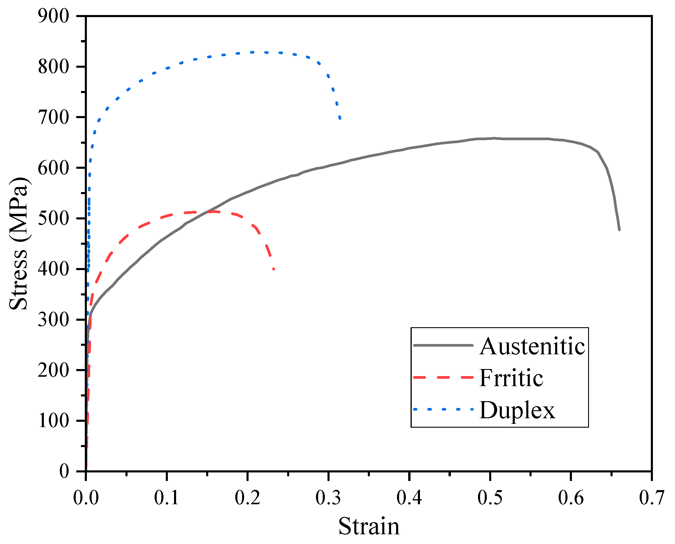
2.1.2. Stainless Steel

Stainless steel is also an important member in the steel structure family, which has been used in construction for decades [27,28]. The prominent stress-strain characteristic of stainless steel is that it has no yielding plateau, as shown in Figure 2. The two-stage Ramberg–Osgood model [29] is often adopted as the constitutive model of stainless steel. Several methods were proposed [30,31,32] to predict the strain at the ultimate tensile stress and the strain hardening exponents, where the 0.2% proof stress measured from the experimental stress-strain response is taken as the material yield strength. Nominal values of the yield strength fy and the ultimate strength fu of different stainless steel provided by EN 1993-1-4 [33] are given in Table 1. EN 1993-1-4 [33] and EN 10088-1 [34] give a value of 200 × 103 N/mm2 for the modulus of elasticity for all of the standard austenitic and duplex grades that are typically used in structural applications. For ferritic grades, a value of 220 × 103 N/mm2 is given. However, tests on ferritic stainless steels consistently indicate that a value of 200 × 103 N/mm2 is more appropriate [35,36]. Therefore, it is expected that the next revision of EN 1993-1-4 will recommend 200 × 103 N/mm2 to be used for the structural design for all stainless steels.
The material properties of cold-formed steel sections illustrate a typical feature that the corner regions of CFS cross sections have a higher yield strength than the other parts. Essentially, strain hardening occurred in the cold-forming process, and this resulted in an increase in strength. The effect is more significant in stainless steel sections than in conventional carbon steel sections due to the shape of the stress-strain curve and the high ratio of ultimate to yield strength. The strength enhancement effects were studied, and several models [32,38,39,40] were proposed for predicting the enhancement effect. The enhanced yield strength is presented as a function of the unformed material’s yield and its ultimate tensile strength as well as the approximate level of strain induced during the forming.

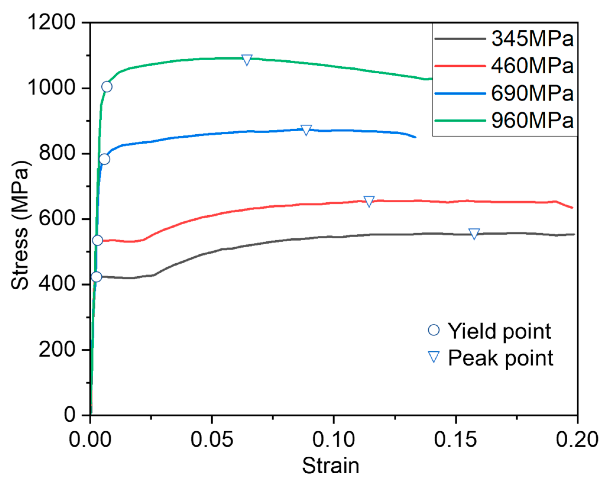
2.1.3. High Strength Steel

High Strength Steel (HSS) refers to a type of steel that exhibits higher strength and great anti-corrosion properties compared to conventional steel due to the presence of alloys, such as manganese, silicon, and phosphorus. Generally, the steel with yield stress not less than 460 MPa can be defined as a high strength steel [41]. The steel is typically used in applications where high levels of strength are required, such as in the construction of bridges, stadiums, and high-rise buildings. The use of HSS enables designers and engineers to achieve structural integrity while reducing material weight and costs.
Compared to mild steel, HSS exhibits different material properties beyond the yield point. Figure 3 shows a comparison of typical stress–strain curves for various steel grades. Based on standard tension coupon tests, ref.[42] has pointed out the length of the yield plateau decrease with an increase in the yield stress, and this normally disappears when the yield strength is not less than 500 MPa. The strains corresponding to ultimate tensile strengths are lower for steels with higher yield strengths, which implies that the ductility of HSS is worse. The strain hardening of high strength steel is also less significant that of normal strength steel [43].
For conveniently modeling the behavior of HSS, several constitutive models have been proposed, including multi-linear models, a non-linear model based on the Ramberg-Osgood model, and a revised multi-linear model, as shown in Figure 4. The model shown in Figure 4a is used for HSS with yield plateaus, while the others are used for HSS without yield plateaus. The parameters of the models may be determined according to [44].

2.2. Residual Stress

Another factor that would cause material nonlinearity and influence the stability of the member is residual stress. The superposition of residual stresses with external loading may cause premature yielding and reduce the stiffness of the structure, thereby increasing deflections and second-order effects. Residual stress is initial self-balancing stress in steel sections that results from non-uniform heating or cooling during fabrication [45]. The distribution of residual stresses depends on dimensions of web and flanges as well as steel grade and fabrication procedures. The stresses in hot-rolled and welded cross sections are clearly distinct, as shown in Figure 5, according to ECCS [46]. In the figures, σt and σc denote the residual tensile and compressive stresses, respectively. The subscripts f and s stand for the flanges and web, respectively. Different residual stress patterns were also proposed for different materials, section types, and fabrication methods [47,48,49,50,51,52,53]. Based on residual stress models, the development of plasticity on a section and the variation of the section properties can be easily evaluated. Conventionally, residual stress models were developed based on experiments, where the hole-drilling and sectioning methods are frequently used [54,55,56]. For practical structural design, the effects of residual stress are generally considered through the column buckling curves. However, the conventional residual stress patterns were derived based on limited test data and ordinary steel grade. Research has illustrated that the residual stress patterns would considerably influence the member buckling behaviors, and some patterns would provide non-conservative results of the ultimate capacity [57]. Moreover, with the development of modern structures, the shapes and sizes of cross sections significantly different to traditional steel members would be used where the specified residual stress patterns may be inapplicable. Therefore, the finite element method is introduced to investigate the residual stress distributions as the actual heating or cooling process can be explicitly simulated in numerical analysis [58,59,60,61]. The simplified residual stress patterns can be easily and directly modeled in numerical analysis of member buckling behaviors. With the increasing use of advanced analysis, accurate patterns of the initial stress are becoming ever more important for modern structural design.

3. Geometrically Nonlinear Effect

3.1. Influences of Global Deformations

A geometrically nonlinear effect refers to the mechanical response of an object that is influenced by its deformation. Examples of geometric nonlinearity include large deflections or rotations as well as snap-through and load stiffening. The large deflections, including the rigid-body movements, could change the structural shape and, hence, its stiffness, and this cannot be accurately described using linear theory. Additionally, as the direction of a load always keeps constant in structural engineering, large deformations would influence the internal force components of structural members, as shown in Figure 6.
Geometrically nonlinear behaviors depend on many factors, including the configuration of the structural system, the material properties, boundary conditions, and the applied loads. The geometrically nonlinear behaviors unusually result in a compression member buckling or instability, leading to sudden and significant deflections of a structure under certain loads. The buckling of a frame member can be caused by flexural or torsional load, and it can be categorized as flexural, torsional, and flexural-torsional buckling. Symmetry of a member cross section can also affect its deformations under stress: a non-symmetric system may twist under compression, for example, leading to unexpected nonlinear buckling behaviors. As buckling could occur before the stress reaches the yield point, the buckling is usually considered separately from the stress strength design. The conventional stability design methods adopt effective length factors in order to evaluate the member buckling strength with different boundary conditions. The effective length factors are a function of material stiffness and slenderness. Traditional research has proposed different effective length, moment magnification factors, and design equations for different buckling modes [62,63,64,65]. Based on the equations and coefficients, the global structural design is often replaced by the stability check of individual structure members. However, the member stability design method is developed based on several simplified assumptions or typical structural forms. For instance, the frame stability design method adopts the simplified assumptions, adjoining columns in the storey above and below the buckle simultaneously in order to consider, conservatively, the interactions between the members. For modern structural system, such as modular constructions and tapered members, where the system and connection behaviors are different to conventional frames, the accurate calculation of the effective length is difficult.

3.2. Geometric Imperfections

The fundamental factors that cause member buckling include initial imperfection and rotational boundary conditions. Structural initial imperfection refers to any deviation from the ideal geometry of a structural member that is present before any external load is applied. Small imperfections can amplify the member deformation under compression loading by introducing second-order moments, which leads to a failure at loads much lower than expected. The buckling loads of the long slender column, considering initial out-of-straightness, can be approximately predicted using the Perry–Robertson formula, which is the basis for the buckling formulation that is adopted in EN 1993-1-1 [17]. Subsequently, the buckling curves in EN 1993-1-1 [17] are developed with varied section types and axes of buckling. However, the limitation of the effective length method is distinct in the analysis of structures with significant P-Δ effects. According to AISC360-22 [18], the effective length is only valid when the ratio of the maximum second-order drift to the maximum first-order drift in all storeys is less equal than 1.5.
One of the major factors contributing to the P-Δ effects is the structural global imperfection. According to EN 1993-1-1, the initial imperfection of a frame is shown in Figure 7. Three methods, namely, the eigen-buckling mode, the notional force, and the direct modeling methods, are commonly used to simulate global imperfections. The eigen-buckling mode method adopts the first eigen-buckling mode or composite eigen-buckling modes as the structural initial imperfection, where eigen-buckling analysis should be conducted before structural nonlinear analysis. The notional force method uses equivalent forces to generate the global imperfection, as shown in Figure 8. The coefficient of the equivalent force can be calculated as ϕ = ϕ 0 α h α m , where ϕ 0 = 1 / 200 is the basic value; α h = 2 h but 2 / 3 α h 1.0 is the reduction factor for columns with height h; α m = 0.5 1 + 1 m is the reduction factor for the number of the column; and m is the number of columns in a row. The notional force method requires calculation of the equivalent horizonal loads. However, the loads would induce additional load to structural internal forces and support reactions; therefore, additional pre- and post-processes are required. The codes also only provide the calculation method of the equivalent load for frame structures. For other structural forms, such as reticulated shell structure, the notional force method is difficult to apply. The direct modeling method directly builds the numerical model with initial imperfection by shifting the nodes to a certain or random position. The method requires a huge modeling effort for large structures, and it may generate an imperfection that contributes to structural capacity. Analysis appropriately considering the structural influences of global imperfections would obtain a more reliable member response, and the modelling method of complex global imperfections is currently one the research hotspots of advanced structural analysis [66,67,68,69].
For member imperfection, a half-sinusoidal or parabolic shape with specified amplitude provided in design codes, such as EN 1993-1-1 [17], AISC-360-22 [18], and GB50017-2017 [19], is usually used for member initial imperfections. The imperfection values specified by EN 1993-1-1 are given in Table 2, where e0 is the value of imperfection and L is the member length. The classification of the buckling curves can be seen in Table 6.2 of EN 1993-1-1 [17], which depends on section types, fabrication process, and plate thickness. The imperfection values are used for equivalent imperfection, which directly incorporate the influences of residual stress. AISC360 adopts a unified value, L/1000, as the initial imperfection of the member. The effects of residual stress are considered through stiffness reduction factors in nonlinear analysis. Similar to global imperfection, EN1993-1-1 provides the notional force method for member imperfection, as shown in Figure 9. For more conveniently considering the member initial imperfection, researchers derived the beam-column element, which incorporates the effects of member imperfection [70], as shown in Figure 10. The element is developed based on high-order shape function, which improves the element accuracy and enables nonlinear analysis with less elements.

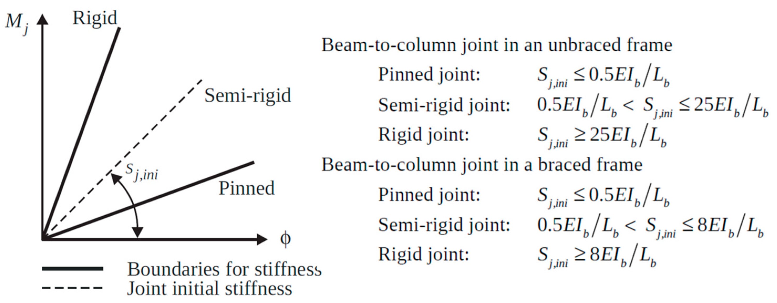
3.3. Rotational Stiffness of Joints

The rotational stiffness of joints and supports has an influence on the P-Δ effects as well. A significant source of inaccuracy in the design of columns using the effective length method is uncertainty in the estimation of rotational boundary conditions for the column [71,72]. The effective length method adopting the idealized joint assumption would obtain incorrect internal forces of a member, especially the internal moments, which would affect the design of connections and, subsequently, the behaviors of the adjacent members.
According to the rotational stiffness, joints can be classified as pin, rigid, and semi-rigid joints. For frame structures, the joint classification can be referred to as it is presented in Figure 11, where K = I / L ; I is the second moment of inertia; L is the length of the member; and the subscripts c and b stand for the columns and beams, respectively.
EN1993-1-8 suggests a bi-linear moment-rotational curve for inelastic structural analysis, as shown in Figure 12. Some other models for typical joint types, such as end-plate connections [74], single-and double-web angle connections [75], and top and seat angle connections [76] obtained from regression can be found in the literature.
The conventional numerical simulate method usually adopts spring elements to simulate the nonlinear behaviors of semi-rigid connections. The proposed moment-rotation model would be used as the constitutive relation of the springs. The conventional modeling method has to build the beam-column elements and the end springs element into the analysis of the program. Some scholars have proposed the element directly incorporating the end springs in the element formulation, as shown in Figure 13. The stiffness matrix of the spring element is condensed into the beam-column element stiffness matrix, which greatly reduces the modeling efforts and improves the computational efficiency.

3.4. Local Buckling

Local buckling refers to the buckling or the deformation that happens in a specific localized region of a structural element rather than its entire length. The main effect of local buckling is that it causes a redistribution of the longitudinal stress, resulting in an increase in stress at the plate near the buckling area. Local buckling usually occurs in thin-walled sections, and design codes are therefore often required to create a section classification before stability design to ensure that the local buckling can be appropriately considered. In a beam, local buckling may manifest as lateral distortions or waves along the length, and may result in a formation of local kinks or curvatures in a column. This effect leads to ultimate loads below the squash load of the section.
Design methods for addressing local buckling in structural elements typically involve ensuring that the member’s cross section is adequately resistant to buckling via various approaches. The most classic methods for considering the local buckling effect are the effective width method and the direct strength method [78]. The effective width method involves determining an effective width for the cross section based on the boundary conditions and the geometry of the element. The effective width represents the portion of the cross section that is expected to carry the majority of the applied loads. By considering the effective width, the designer can calculate the buckling resistance of the element using appropriate formulas or design guidelines. However, the method ignores equilibrium and compatibility between the flange and the web in determining the elastic buckling behavior. For members with folded-in stiffeners, the calculation of different effective widths along the member is cumbersome [79]. To simplify the design process, the direct strength method is proposed. The method involves calculating the strength and stability of the cross section directly, considering both elastic and plastic behaviors. The fundamental idea behind the direct strength method is based on accurate member stability, as shown in Figure 14. The finite strip method is usually used to determine the member stability capacity and the strength reduction factors. Some studies [80,81,82] have also derived the reduction factors based on experiments.
To mitigate the potential effects of local buckling, several design strategies can be employed. These include increasing the section thickness, using stronger materials, providing intermediate supports, adding stiffeners or reinforcements, or altering the section shape to improve its stability.
The direct analysis method is also suggested by design guidelines for thin-walled members [78]. EN1993-1-5 [24] Table C.2 provides the value of member initial imperfections as shown in Table 3. These guidelines help designers ensure that structural members are designed to withstand the anticipated loading conditions and prevent local buckling failures.

4. Analysis and Design

It is necessary to consider structural nonlinear effects in structural analysis and design. The commonly adopted method for simulating and predicting the nonlinear effects in structural engineering is the finite element method. The advantage of the finite element method is the possibility of simulating different structural properties, such as initial imperfection, special section configuration, and boundary conditions for a wide class of problems. The forces and the displacements within and between each element are calculated by solving non-linear mechanics equations. Therefore, sophisticated and comprehensive mathematical models are required to accurately predict the structural nonlinear response. Various finite element modeling procedures, including different elements, iterative methods, calculation of section properties, and coupling techniques, have been developed for nonlinear analysis. Based on rigorous numerical analysis results, structures can be reliably optimized to prevent failure.
The finite element method’s critical and challenging aspect is the accurate and efficient evaluation of the member P-δ effect. Different methods, such as the stiffness reduction method [83,84,85], the notational forces method [17,18,19,20], and the column element with initial imperfection [86,87,88], have been proposed.
Figure 15 illustrates and compares several structural analysis methods. The figure shows that among all of the analysis methods, advanced analysis that explicitly considers system effects, such as load redistribution after first yielding, can more accurately predict the behavior and the ultimate load-carrying capacity of a structural system. By using the advanced analysis method, the system failure mode becomes apparent, and it is thereby possible to consider the consequences of failure in the design process [89].

4.1. Linear Analysis

Linear analysis, which has been used for decades, assumes that the deflection is proportional to the applied force. Thus, it is possible to superimpose force diagrams of various loads in order to obtain the final force analysis of the structure. This method simply evaluates the distribution of forces in the structure that do not provide any information on structural stability or true capacity. When second-order effects of the structure cannot be ignored, other approaches must be employed to check the safety of a structure.
A commonly used method to consider the second-order effect is the moment amplification method, which enlarges the bending moment of linear analysis using amplification factors as follows:
M u = B 1 M n t + B 2 M l t
where B1 and B2 are the moment amplification factors, and where Mnt and Mlt are the first-order moments ignoring and considering lateral translation.
For the axial compressed member, the design codes provide the reduction factors in order to consider the effects of the initial imperfection of the member and the residual stress. For instance, the buckling curves, as shown Figure 16, that are presented by EN1993-1-1 provide the evaluation method of the ultimate capacity for a column’s flexural buckling with different section types.
In the buckling analysis, the linear method treats the member as a defect-free axial compression member. When the axial load does not exceed an eigenvalue, the member remains straight, and it only generates uniform compressive stress on the section. When the pressure reaches a certain limit value greater than critical axial load, the member will suddenly buckle, transforming from the original equilibrium into a new equilibrium form adjacent to it but bending. An eigenvalue problem is formulated by a standard procedure as follows:
K L + λ c r K G = 0
where K L and K G are the linear and the geometric stiffness matrices.
Eigenvalue buckling does not give a load-displacement curve, but it does give a single load value when the structure is buckling. This method is simple to calculate and is the upper limit of the results of nonlinear buckling analysis, and it is therefore still widely used.

4.2. Geometric Nonlinear Analysis

Compared with the linear analysis, structural geometric nonlinear deformation requires more complex formulas to describe. Therefore, the numerical method is generally adopted to capture the geometrically nonlinear effect. The Hermite beam-column element using cubic shape function is the most widely used beam-column in structural analysis. The bowing effect is introduced to the potential energy equation of the element in order to derive the geometric stiffness matrix. For severe member deformations where the accuracy of the Hermite interpolation function is not enough, some advanced elements incorporating internal degrees of freedom are developed in order to improve the element’s deformation capacity [90,91,92]. Beam-column elements with high-order shape functions have also been developed. Chan and Zhou [93] proposed a Pointwise Equilibrating Polynomial (PEP) Euler beam-column element by considering the equilibrium at midspan, and Tang [94] updated the PEP element into the Timoshenko format.
Along with the evolution of the element technique, the kinematic description of the motion of a largely deformed element is developed for simplifying the element stiffness matrix expression. There are three common categories for describing the process of structural motion: total Lagrangian (TL) formulation, updated Lagrangian (UL) formulation, and co-rotational (CR) formulation [95]. All variables described in the TL format take the configuration at the initial moment as the reference configuration, and all of the variables described in the UL format take the known configuration of the previous step as the reference configuration. The CR format is usually the known configuration of the above step as a reference configuration, but its reference configuration is with the unit continuous rigid body translation and rigid body rotation, so in the formula of the CR format unit, the freedom will not include the unit rigid body displacement part.

4.3. Post-Buckling Analysis

Post-buckling behavior refers to the response of a structure after buckling. In the post-buckling phase, the behavior of the structure can be complex and nonlinear. Post-buckling analysis aims to investigate the response of the structure beyond the point of buckling, and to understand its structural stability, load-carrying capacity, and potential collapse patterns. The analysis usually encounters the problem of convergence. The Newton–Raphson method is often used in the nonlinear iteration method. However, it is well known that the load control Newton–Raphson method could diverge near the limit point to capture the unloading stage of the post-buckling behavior. To address this defect, Zienkiewicz [96] proposed a displacement control method, which adopts a constant displacement increment for each iteration. Obviously, when the control displacement tends to retrace in the load-deflection curve, such as snap-back buckling, this method may be ineffective. Therefore, the arc length method maintaining a constant arc length in the iterative process has been proposed [97]. This method is a better choice than the abovementioned methods in post-buckling analysis because it can deal with a loading variation due to yielding and cohesive effects. However, the arc-length method is also controversial because it initially guess dependent, relying on an initial guess for the solution trajectory. The accuracy and efficiency of the method can be affected by the quality of this initial guess, making it important to carefully select or refine the initial estimation. In addition, by using arc length as a constraint to guide the iteration, it still cannot be guaranteed that it can guide the direction of the iteration correctly in the range of post-buckling that involves multi-loop curved lines.

4.4. Material Nonlinear Analysis

In inelastic analysis of steel frame structures, the material nonlinearity is simulated by two methods––namely, the plastic zone method and the plastic hinge method. The plastic zone assumes that the yield is distributed throughout the section and along the element. In the plastic zone method, elements of the structure must be discretized into several sub-element and fiber sections in order to accurately reflect the development of plasticity [98]. This method consumes a lot of computer resources and computational time due to its numerous elements, and it has generally been deemed impractical in design practices.
In order to solve the shortcomings of the plastic zone method in computational time, the plastic hinge method, which assumes that the plastic behavior of an element is concentrated at the nodes, has been developed. The method considers the plasticity by adding a zero-length plastic spring at the failed end of the element, while the other parts of the element remain completely elastic. Combining the advanced element technique with the plastic hinge method can capture inelastic second-order effects using one element per member method. When the plasticity occurs within the element nodes, the plastic hinge method may not be able to truly reflect member behaviors. However, the accuracy of this method is sufficient for practical purposes.

4.5. Direct Analysis Method

For accurately simulating the structural nonlinear performances, material and geometric nonlinearities should be considered simultaneously in structural analysis in order to reflect the effects between structural deformations and the development of plasticity [99,100]. It is therefore necessary to conduct second-order inelastic analysis, especially for irregular structural forms. However, effects of nonlinear parameters, such as initial imperfections, joint stiffness, and residual stress, are tedious to model with traditional finite element methods. Walport et al. [101] pointed out the conventional bow imperfection provided by EN 1993-1-1 [17] is only suitable to second-order elastic analysis, and they proposed new equivalent geometric imperfections that incorporate the residual stress effects for inelastic analysis. Bai et al. [102] proposed an initial imperfection shape for the flexural buckling strength design of tapered I members. The directions of the initial member imperfections are generally set the same as the global eigen-buckling mode or the load deflection mode, and this is to generate the most adverse initial configuration. By adopting the most adverse imperfection, the uncertainty of imperfection is eliminated in the numerical analysis. Several researchers have also proposed advanced numerical methods to consider the influences of semi-rigid connections [103,104,105] and distributed plasticity [106,107,108]. With the help of advanced numerical methods, the analysis method incorporating structural nonlinear influences directly into nonlinear structural analysis is developed [109,110,111].
In the direct analysis method, advanced computational techniques, which consider the actual stiffness, mass distributions, and load patterns of the structure, are employed [112]. The method considers the second-order effects in the analysis in order to ensure that members can be directly designed according to the section bearing capacity without using effect length factors. In other words, only the section capacity check is needed for the member design. This method is not only applicable to prismatic members but also to the members of the variable section by using a different initial geometrical imperfection pattern [113]. However, at the present stage, the torsional and flexural-torsional buckling cannot be directly evaluated based on the sectional capacity, as the warping degree of freedom could not be well considered in the analysis, and the out-of-plane buckling of compression-flexure members needs to be further studied.

5. Outlook

The nonlinear problem of steel structures is becoming complex with the developments of innovative structural forms and new functional requirements on structures. Conventional design methods, such as the effective length method, are mainly develop based on the elastic analysis method. For the design needs to consider the structural inelastic performance, such as fire or seismic resistance analysis, the effective length design method may inaccurately predict the member capacity, which is usually conservative in frame design [114,115]. Therefore, the accuracy calculation of the effective length factors is always an important and difficult issue in steel structural engineering.
To avoid the uncertainties induced by the simplified or empirical design assumptions of conventional design methods, advanced analysis and design methods––namely, the directly analysis method––has been extensively studied. The advanced beam-column elements have been proposed for both geometric and material analysis. Some elements can be adopted in the analysis using the one-element-per-member modeling method. However, at the current stage, the directly analysis method can only be adopted for member flexural buckling design. For lateral-torsional and local buckling design, empirical equations are still used in practice. For seismic design, the predominant approach is the response spectrum analysis method, and it is basically a linear method. Thus, straightforward advanced methods for dynamic stability design, including seismic, fire, and progressive collapse design, need to be studied.

6. Conclusions

The non-linear behavior of steel structures is a result of their inherent properties and their behavior under loading. It is important to consider these effects in the design and analysis of steel structures in order to ensure their safety and their efficient performance. The structural nonlinear problem is very complex, as the influences of initial imperfection, residual stress, and large deformations are coupled and also interact. Research has developed different methods to consider structural nonlinear characteristics. In current design practices, the finite element method and other advanced analytical techniques are employed to model non-linear behavior. Design codes and standards provide guidelines for the design of steel structures under non-linear conditions. However, there are many unsolved problems in the research field of steel structural stability, such as the nonlinear dynamic stability problems of long-span bridges, long-span thin shells, long-span space latticed shells, and high-rise structures. With the technical development of fabrication and construction, some innovative and elaborate analysis and design approaches will be required to evaluate the nonlinear characteristics of modern steel structures. Designers and engineers must be aware of non-linear behavior, and they must incorporate its effects into their steel structure designs.

Author Contributions

Conceptualization, R.B. and Y.-P.L.; Writing—original draft preparation, Z.-J.Z. and B.-S.C.; Writing—review and editing, R.B.; Supervision, Y.-P.L. All authors have read and agreed to the published version of the manuscript.

Funding

This study was supported by grants from Marine Economy Development Project of Guangdong Province (GDNRC[2023]29).

Data Availability Statement

Data available in a publicly accessible repository. The data presented in this study are openly available in corresponding references.

Conflicts of Interest

The authors declare no conflict of interest.

References

  1. Chan, S.L. Non-linear behavior and design of steel structures. J. Constr. Steel Res. 2001, 57, 1217–1231. [Google Scholar]
  2. Kala, Z. Stability problems of steel structures in the presence of stochastic and fuzzy uncertainty. Thin Walled Struct. 2007, 45, 861–865. [Google Scholar] [CrossRef]
  3. Selvaraj, S.; Madhavan, M. Design of cold-formed steel built-up columns subjected to local-global interactive buckling using direct strength method. Thin Walled Struct. 2021, 159, 107305. [Google Scholar]
  4. Zhang, Z.; Xu, S.; Wang, H.; Nie, B.; Su, C. Flexural buckling behavior of corroded hot-rolled H-section steel beams. Eng. Struct. 2021, 229, 111614. [Google Scholar]
  5. Ziemian, C.; Ziemian, R. Efficient geometric nonlinear elastic analysis for design of steel structures: Benchmark studies. J. Constr. Steel Res. 2021, 186, 106870. [Google Scholar]
  6. Quan, C.; Walport, F.; Gardner, L. Equivalent imperfections for the out-of-plane stability design of steel beams by second-order inelastic analysis. Eng. Struct. 2022, 251, 113481. [Google Scholar]
  7. Adluri, S.M.R.; Madugula, M.K. Flexural buckling of steel angles: Experimental investigation. J. Struct. Eng. 1996, 122, 309–317. [Google Scholar] [CrossRef]
  8. Taras, A.; Greiner, R. New design curves for lateral–torsional buckling—Proposal based on a consistent derivation. J. Constr. Steel Res. 2010, 66, 648–663. [Google Scholar]
  9. Wang, J.; Gardner, L. Flexural buckling of hot-finished high-strength steel SHS and RHS columns. J. Struct. Eng. 2017, 143, 04017028. [Google Scholar]
  10. Duan, L.; Chen, W.F. Effective length factor for columns in unbraced frames. J. Struct. Eng. 1989, 115, 149–165. [Google Scholar]
  11. Kishi, N.; Chen, W.; Goto, Y. Effective length factor of columns in semirigid and unbraced frames. J. Struct. Eng. 1997, 123, 313–320. [Google Scholar]
  12. Chen, S.J.; Wang, W.C. Moment amplification factor for P-δ effect of steel beam-column. J. Struct. Eng. 1999, 125, 219–223. [Google Scholar] [CrossRef]
  13. Serna, M.A.; López, A.; Puente, I.; Yong, D.J. Equivalent uniform moment factors for lateral–torsional buckling of steel members. J. Constr. Steel Res. 2006, 62, 566–580. [Google Scholar] [CrossRef]
  14. Clarke, M.; Bridge, R.; Hancock, G.; Trahair, N. Advanced analysis of steel building frames. J. Constr. Steel Res. 1992, 23, 1–29. [Google Scholar]
  15. Surovek, A.E.; White, D.W.; Leon, R.T. Direct analysis for design evaluation of partially restrained steel framing systems. J. Struct. Eng. 2005, 131, 1376–1389. [Google Scholar] [CrossRef]
  16. Li, T.J.; Liu, S.W.; Chan, S.L. Direct analysis for high-strength steel frames with explicit-model of residual stresses. Eng. Struct. 2015, 100, 342–355. [Google Scholar]
  17. EN1993-1-1; Eurocode 3: Design of Steel Structures. Part 1-1: General Rules and Rules for Buildings. European Committee for Standardization: Brussels, Belgium, 2005.
  18. ANSI/AISC-360-22; Specification for Structural Steel Buildings. AISC Committee: Chicago, IL, USA, 2022.
  19. GB50017-2017; Code for Design of Steel Structures. China Architecture & Building Press Beijing: Beijing, China, 2017.
  20. AS4100-1998; Steel Structures. Standards Australia: Sydney, Australia, 2020.
  21. Eröz, M.; White, D.W.; DesRoches, R. Direct analysis and design of steel frames accounting for partially restrained column base conditions. J. Struct. Eng. 2008, 134, 1508–1517. [Google Scholar] [CrossRef]
  22. Bai, R.; Hajjar, J.F.; Liu, S.-W.; Chan, S.-L. A mixed-field Timoshenko beam-column element for direct analysis of tapered I-sections members. J. Constr. Steel Res. 2020, 172, 106157. [Google Scholar]
  23. Du, Z.L.; Liu, Y.P.; He, J.W.; Chan, S.L. Direct analysis method for noncompact and slender concrete-filled steel tube members. Thin Walled Struct. 2019, 135, 173–184. [Google Scholar]
  24. EN1993-1-5; Eurocode 3: Design of Steel Structures. Part 1-5: Plated Structural Elements. European Committee for Standardization: Brussels, Belgium, 2006.
  25. Bai, Z.Z.; Au, F.T.K. Effects of strain hardening of reinforcement on flexural strength and ductility of reinforced concrete columns. Struct. Des. Tall Spec. Build. 2011, 20, 784–800. [Google Scholar] [CrossRef]
  26. Johansson, B.; Maquoi, R.; Sedlacek, G.; Müller, C.; Beg, D. Commentary and Worked Examples to EN 1993-1-5 Plated Structural Elements. JRC Scientific and Technical Reports. 2007. Available online: https://publications.jrc.ec.europa.eu/repository/handle/JRC38239 (accessed on 30 June 2023).
  27. Baddoo, N. Stainless steel in construction: A review of research, applications, challenges and opportunities. J. Constr. Steel Res. 2008, 64, 1199–1206. [Google Scholar]
  28. Wang, F.C.; Han, L.H. Analytical behavior of carbon steel-concrete-stainless steel double-skin tube (DST) used in submarine pipeline structure. Mar. Struct. 2019, 63, 99–116. [Google Scholar]
  29. Ramberg, W.; Osgood, W.R. Description of Stress-Strain Curves by Three Parameters. No. NACA-TN-902. 1943. Available online: https://ntrs.nasa.gov/citations/19930081614 (accessed on 30 June 2023).
  30. Rasmussen, K.J. Full-range stress–strain curves for stainless steel alloys. J. Constr. Steel Res. 2003, 59, 47–61. [Google Scholar] [CrossRef]
  31. Arrayago, I.; Real, E.; Gardner, L. Description of stress–strain curves for stainless steel alloys. Mater. Des. 2015, 87, 540–552. [Google Scholar]
  32. Gardner, L.; Yun, X. Description of stress-strain curves for cold-formed steels. Constr. Build. Mater. 2018, 189, 527–538. [Google Scholar]
  33. EN1993-1-4; Eurocode 3: Design of Steel Structures. Part 1-4: General Rules—Supplementary Rules for Stainless Steels. European Committee for Standardization: Brussels, Belgium, 2006.
  34. EN10088-1; EN 10088-1: Stainless Steels Part 1: List of Stainless Steels. European Committee for Standardization: Brussels, Belgium, 2014.
  35. Li, H.-T.; Young, B. Cold-formed ferritic stainless steel tubular structural members subjected to concentrated bearing loads. Eng. Struct. 2017, 145, 392–405. [Google Scholar]
  36. Afshan, S.; Arrayago Luquin, I.; Gardner, L.; Gedge, G.; Jandera, M.; Real Saladrigas, E.; Rossi, B.; Stranghoner, N.; Zhao, O. Design Manual for Structural Stainless Steel; Steel Construction Institute Publications: Berkshire, UK, 2017. [Google Scholar]
  37. Gardner, L. Stability and design of stainless steel structures–Review and outlook. Thin Walled Struct. 2019, 141, 208–216. [Google Scholar]
  38. Afshan, S.; Rossi, B.; Gardner, L. Strength enhancements in cold-formed structural sections—Part I: Material testing. J. Constr. Steel Res. 2013, 83, 177–188. [Google Scholar]
  39. Quach, W.; Qiu, P. Strength and ductility of corner materials in cold-formed stainless steel sections. Thin Walled Struct. 2014, 83, 28–42. [Google Scholar]
  40. Wang, J.; Shu, G.; Zheng, B.; Jiang, Q. Investigations on cold-forming effect of cold-drawn duplex stainless steel tubular sections. J. Constr. Steel Res. 2019, 152, 81–93. [Google Scholar]
  41. EN10025-6; Hot Rolled Products of Structural Steels–Part 6: Technical Delivery Conditions for Flat Products of High Yield Strength Structural Steels in the Quenched and Tempered Condition. European Committee for Standardization: Brussels, Belgium, 2019.
  42. Ban, H.Y.; Shi, G. A review of research on high-strength steel structures. Proc. Inst. Civ. Eng. Struct. Build. 2018, 171, 625–641. [Google Scholar]
  43. Wang, Y.-B.; Li, G.-Q.; Cui, W.; Chen, S.-W.; Sun, F.-F. Experimental investigation and modeling of cyclic behavior of high strength steel. J. Constr. Steel Res. 2015, 104, 37–48. [Google Scholar]
  44. Shi, G.; Zhu, X.; Ban, H.Y. Material properties and partial factors for resistance of high-strength steels in China. J. Constr. Steel Res. 2016, 121, 65–79. [Google Scholar]
  45. Abambres, M.; Quach, W.M. Residual stresses in steel members: A review of available analytical expressions. Int. J. Struct. Integr. 2016, 7, 70–94. [Google Scholar]
  46. ECCS. Ultimate limit state calculation of sway frames with rigid joints. In European Convention for Constructional Steelwork. Technical Committee 8, Structural Stability; European Convention of Constructional Steel Work: Brussels, Belgium, 1984. [Google Scholar]
  47. Szalai, J.; Papp, F. A new residual stress distribution for hot-rolled I-shaped sections. J. Constr. Steel Res. 2005, 61, 845–861. [Google Scholar]
  48. Wang, Y.B.; Li, G.Q.; Chen, S.W. The assessment of residual stresses in welded high strength steel box sections. J. Constr. Steel Res. 2012, 76, 93–99. [Google Scholar]
  49. Ma, J.L.; Chan, T.M.; Young, B. Material properties and residual stresses of cold-formed high strength steel hollow sections. J. Constr. Steel Res. 2015, 109, 152–165. [Google Scholar]
  50. Yang, B.; Nie, S.; Xiong, G.; Hu, Y.; Bai, J.; Zhang, W.; Dai, G. Residual stresses in welded I-shaped sections fabricated from Q460GJ structural steel plates. J. Constr. Steel Res. 2016, 122, 261–273. [Google Scholar]
  51. Zhang, Z.; Shi, G.; Chen, X.; Wang, L.; Zhou, L. Residual stress measurements and modeling of built-up Box-T sections. Thin-Walled Struct. 2021, 160, 107336. [Google Scholar]
  52. Schaper, L.; Tankova, T.; da Silva, L.S.; Knobloch, M. A novel residual stress model for welded I-sections. J. Constr. Steel Res. 2022, 188, 107017. [Google Scholar]
  53. Yun, X.; Zhu, Y.; Meng, X.; Gardner, L. Welded steel I-section columns: Residual stresses, testing, simulation and design. Eng. Struct. 2023, 282, 115631. [Google Scholar]
  54. Li, Y.; Wu, J.; Qiang, B.; Zhou, S.; Liu, W.; Yao, C. Measurements of residual stresses in a welded orthotropic steel deck by the hole-drilling method considering stress biaxiality. Eng. Struct. 2021, 230, 111690. [Google Scholar]
  55. Peng, Y.; Zhao, J.; Chen, L.-s.; Dong, J. Residual stress measurement combining blind-hole drilling and digital image correlation approach. J. Constr. Steel Res. 2021, 176, 106346. [Google Scholar]
  56. Jiang, X.; Wei, Y.; Zhou, J.; Zhan, K.; Ding, Z.; Liang, S.Y. Residual stress generation and evaluation in milling: A review. Int. J. Adv. Manuf. Technol. 2023, 126, 3783–3812. [Google Scholar]
  57. Rossi, A.; Saito, D.H.; Martins, C.H.; de Souza, A.S.C. The influence of structural imperfections on the LTB strength of I-beams. In Structures; Elsevier: Amsterdam, The Netherlands, 2021. [Google Scholar]
  58. Rong, Y.; Xu, J.; Huang, Y.; Zhang, G. Review on finite element analysis of welding deformation and residual stress. Sci. Technol. Weld. Join. 2018, 23, 198–208. [Google Scholar]
  59. Yao, Y.; Quach, W.M.; Young, B. Finite element-based method for residual stresses and plastic strains in cold-formed steel hollow sections. Eng. Struct. 2019, 188, 24–42. [Google Scholar]
  60. Taraphdar, P.; Kumar, R.; Pandey, C.; Mahapatra, M. Significance of finite element models and solid-state phase transformation on the evaluation of weld induced residual stresses. Met. Mater. Int. 2021, 27, 3478–3492. [Google Scholar] [CrossRef]
  61. Tankova, T.; da Silva, L.S.; Balakrishnam, M.; Rodrigues, D.; Launert, B.; Pasternak, H.; Tun, T.Y. Residual stresses in welded I section steel members. Eng. Struct. 2019, 197, 109398. [Google Scholar]
  62. Hellesland, J. Mechanics and effective lengths of columns with positive and negative end restraints. Eng. Struct. 2007, 29, 3464–3474. [Google Scholar]
  63. Hellesland, J. Second order approximate analysis of unbraced multistorey frames with single curvature regions. Eng. Struct. 2009, 31, 1734–1744. [Google Scholar]
  64. Hellesland, J. Evaluation of effective length formulas and applications in system instability analysis. Eng. Struct. 2012, 45, 405–420. [Google Scholar] [CrossRef]
  65. Gunaydin, A.; Aydin, R. A simplified method for instability and second-order load effects of framed structures: Story-based approach. Struct. Des. Tall Spec. Build. 2019, 28, e1655. [Google Scholar] [CrossRef]
  66. Chen, G.; Zhang, H.; Rasmussen, K.J.; Fan, F. Modeling geometric imperfections for reticulated shell structures using random field theory. Eng. Struct. 2016, 126, 481–489. [Google Scholar] [CrossRef]
  67. Wang, J.; Li, H.-N.; Fu, X.; Li, Q. Geometric imperfections and ultimate capacity analysis of a steel lattice transmission tower. J. Constr. Steel Res. 2021, 183, 106734. [Google Scholar] [CrossRef]
  68. Zhu, S.; Ohsaki, M.; Guo, X. Prediction of non-linear buckling load of imperfect reticulated shell using modified consistent imperfection and machine learning. Eng. Struct. 2021, 226, 111374. [Google Scholar] [CrossRef]
  69. Zeng, Q.; Guo, X.; Yang, X.; Zhu, S.; Li, Z. Constrained Stochastic Imperfection Modal Method for Nonlinear Buckling Analysis of Single-Layer Reticulated Shells. J. Struct. Eng. 2023, 149, 04022265. [Google Scholar] [CrossRef]
  70. Chan, S.L.; Zhou, Z.H. Second-order elastic analysis of frames using single imperfect element per member. J. Struct. Eng. 1995, 121, 939–945. [Google Scholar] [CrossRef]
  71. Gantes, C.J.; Mageirou, G.E. Improved stiffness distribution factors for evaluation of effective buckling lengths in multi-story sway frames. Eng. Struct. 2005, 27, 1113–1124. [Google Scholar] [CrossRef]
  72. Mageirou, G.E.; Gantes, C.J. Buckling strength of multi-story sway, non-sway and partially-sway frames with semi-rigid connections. J. Constr. Steel Res. 2006, 62, 893–905. [Google Scholar] [CrossRef]
  73. EN1993-1-8; Eurocode 3: Design of Steel Structures. Part 1-8: Design of Joints. European Committee for Standardization: Brussels, Belgium, 2009.
  74. Kishi, N.; Chen, W.F. Moment-rotation relations of semirigid connections with angles. J. Struct. Eng. 1990, 116, 1813–1834. [Google Scholar] [CrossRef]
  75. Chisala, M.L. Modelling M–φ curves for standard beam-to-column connections. Eng. Struct. 1999, 21, 1066–1075. [Google Scholar] [CrossRef]
  76. Calado, L.; De Matteis, G.; Landolfo, R. Experimental response of top and seat angle semi-rigid steel frame connections. Mater. Struct. 2000, 33, 499–510. [Google Scholar] [CrossRef]
  77. Jiang, W.-Q.; Liu, Y.-P.; Chan, S.-L.; Wang, Z.-Q. Direct analysis of an ultrahigh-voltage lattice transmission tower considering joint effects. J. Struct. Eng. 2017, 143, 04017009. [Google Scholar] [CrossRef]
  78. AISI-S100-1; North American Specification for the Design of Cold-Formed Steel Structural Members. AISI Committee: Washington, DC, USA, 2016.
  79. Schafer, B.W. The direct strength method of cold-formed steel member design. J. Constr. Steel Res. 2008, 64, 766–778. [Google Scholar] [CrossRef]
  80. Yousefi, A.M.; Samali, B. Design of cold-formed ferritic stainless steel unlipped channels with offset web openings and unfastened flanges subject to web bearing failure under one-flange load scenarios. In Structures; Elsevier: Amsterdam, The Netherlands, 2020; Volume 27, pp. 194–211. [Google Scholar] [CrossRef]
  81. Yousefi, A.M.; Samali, B.; Hajirasouliha, I. Experimental and numerical investigations of cold-formed austenitic stainless steel unlipped channels under bearing loads. Thin Walled Struct. 2020, 152, 106768. [Google Scholar] [CrossRef]
  82. Yousefi, A.M.; Samali, B.; Hajirasouliha, I.; Yu, Y.; Clifton, G.C. Unified design equations for web crippling failure of cold-formed ferritic stainless steel unlipped channel-sections with web hole. J. Build. Eng. 2022, 45, 103685. [Google Scholar] [CrossRef]
  83. Kucukler, M.; Gardner, L.; Macorini, L. Flexural–torsional buckling assessment of steel beam–columns through a stiffness reduction method. Eng. Struct. 2015, 101, 662–676. [Google Scholar] [CrossRef]
  84. Kucukler, M.; Gardner, L.; Macorini, L. A stiffness reduction method for the in-plane design of structural steel elements. Eng. Struct. 2014, 73, 72–84. [Google Scholar] [CrossRef]
  85. González-de-León, I.; Arrayago, I.; Real, E.; Mirambell, E. A stiffness reduction method for the in-plane design of stainless steel members and frames according with EN 1993-1-4. Eng. Struct. 2022, 253, 113740. [Google Scholar] [CrossRef]
  86. Du, Z.L.; Liu, Y.P.; Chan, S.L. A second-order flexibility-based beam-column element with member imperfection. Eng. Struct. 2017, 143, 410–426. [Google Scholar] [CrossRef]
  87. Bai, R.; Liu, S.-W.; Liu, Y.-P.; Chan, S.-L. Direct analysis of tapered-I-section columns by one-element-per-member models with the appropriate geometric-imperfections. Eng. Struct. 2019, 183, 907–921. [Google Scholar] [CrossRef]
  88. Tang, Y.Q.; Ding, Y.Y.; Liu, Y.P.; Chan, S.-L.; Du, E.F. Innovative displacement-based beam-column element with shear deformation and imperfection. Steel Compos. Struct. 2022, 42, 75. [Google Scholar]
  89. Chen, W.-F. Advanced Analysis of Steel Frames: Theory, Software, and Applications; CRC Press: Boca Raton, FL, USA, 2018. [Google Scholar]
  90. Augarde, C.E. Generation of shape functions for straight beam elements. Comput. Struct. 1998, 68, 555–560. [Google Scholar] [CrossRef]
  91. Liu, S.W.; Liu, Y.P.; Chan, S.L. Direct analysis by an arbitrarily-located-plastic-hinge element—Part 1: Planar analysis. J. Constr. Steel Res. 2014, 103, 303–315. [Google Scholar] [CrossRef]
  92. Liu, S.W.; Liu, Y.P.; Chan, S.L. Direct analysis by an arbitrarily-located-plastic-hinge element—Part 2: Spatial analysis. J. Constr. Steel Res. 2014, 103, 316–326. [Google Scholar] [CrossRef]
  93. Chan, S.L.; Zhou, Z.H. Pointwise equilibrating polynomial element for nonlinear analysis of frames. J. Struct. Eng. 1994, 120, 1703–1717. [Google Scholar] [CrossRef]
  94. Tang, Y.Q.; Liu, Y.P.; Chan, S.L.; Du, E.F. An innovative co-rotational pointwise equilibrating polynomial element based on Timoshenko beam theory for second-order analysis. Thin Walled Struct. 2019, 141, 15–27. [Google Scholar] [CrossRef]
  95. De Borst, R.; Crisfield, M.A.; Remmers, J.J.; Verhoosel, C.V. Nonlinear Finite Element Analysis of Solids and Structures; John Wiley & Sons: Hoboken, NJ, USA, 2012. [Google Scholar]
  96. Zienkiewicz, O. Incremental displacement in non-linear analysis. Int. J. Numer. Methods Eng. 1971, 3, 587–588. [Google Scholar] [CrossRef]
  97. Crisfield, M.A. A fast incremental/iterative solution procedure that handles “snap-through”. In Computational Methods in Nonlinear Structural and Solid Mechanics; Elsevier: Amsterdam, The Netherlands, 1981; pp. 55–62. [Google Scholar]
  98. Nguyen, P.C.; Kim, S.E. A new improved fiber plastic hinge method accounting for lateral-torsional buckling of 3D steel frames. Thin Walled Struct. 2018, 127, 666–675. [Google Scholar] [CrossRef]
  99. Walport, F.; Gardner, L.; Real, E.; Arrayago, I.; Nethercot, D.A. Effects of material nonlinearity on the global analysis and stability of stainless steel frames. J. Constr. Steel Res. 2019, 152, 173–182. [Google Scholar] [CrossRef]
  100. Quan, C.; Kucukler, M.; Gardner, L. Out-of-plane stability design of steel beams by second-order inelastic analysis with strain limits. Thin Walled Struct. 2021, 169, 108352. [Google Scholar] [CrossRef]
  101. Walport, F.; Gardner, L.; Nethercot, D. Equivalent bow imperfections for use in design by second order inelastic analysis. Structures 2020, 26, 670–685. [Google Scholar] [CrossRef]
  102. Bai, R.; Liu, S.-W.; Chan, S.-L.; Yu, F. Flexural buckling strength of tapered-I-section steel columns based on ANSI/AISC-360-16. Int. J. Struct. Stab. Dyn. 2019, 19, 1950134. [Google Scholar] [CrossRef]
  103. Zhou, Z.H.; Chan, S.L. Self-equilibrating element for second-order analysis of semirigid jointed frames. J. Eng. Mech. 1995, 121, 896–902. [Google Scholar] [CrossRef]
  104. Lien, K.; Chiou, Y.; Hsiao, P. Vector form intrinsic finite-element analysis of steel frames with semirigid joints. J. Struct. Eng. 2012, 138, 327–336. [Google Scholar] [CrossRef]
  105. Liu, S.W.; Chan, J.L.Y.; Bai, R.; Chan, S.L. Curved-quartic-function elements with end-springs in series for direct analysis of steel frames. Steel Compos. Struct. Int. J. 2018, 29, 623–633. [Google Scholar]
  106. Mazza, F. A distributed plasticity model to simulate the biaxial behaviour in the nonlinear analysis of spatial framed structures. Comput. Struct. 2014, 135, 141–154. [Google Scholar] [CrossRef]
  107. Thai, H.T.; Kim, S.E. Second-order distributed plasticity analysis of steel frames with semi-rigid connections. Thin Walled Struct. 2015, 94, 120–128. [Google Scholar] [CrossRef]
  108. Prakash, P.R.; Srivastava, G. Distributed plasticity model for analysis of steel structures subjected to fire using the direct stiffness method. Fire Saf. J. 2019, 105, 169–187. [Google Scholar] [CrossRef]
  109. Chan, S.-L.; Liu, Y.-P.; Liu, S.-W. A new codified design theory of second-order direct analysis for steel and composite structures—From research to practice. In Structures; Elsevier: Amsterdam, The Netherlands, 2017. [Google Scholar]
  110. Liu, S.-W.; Bai, R.; Chan, S.-L.; Liu, Y.-P. Second-order direct analysis of domelike structures consisting of tapered members with I-sections. J. Struct. Eng. 2016, 142, 04016009. [Google Scholar] [CrossRef]
  111. Du, Z.-L.; Ding, Z.-X.; Liu, Y.-P.; Chan, S.-L. Advanced flexibility-based beam-column element allowing for shear deformation and initial imperfection for direct analysis. Eng. Struct. 2019, 199, 109586. [Google Scholar] [CrossRef]
  112. Bai, R.; Liu, S.W.; Chan, S.L. Finite-element implementation for nonlinear static and dynamic frame analysis of tapered members. Eng. Struct. 2018, 172, 358–381. [Google Scholar] [CrossRef]
  113. Chen, W.F.; Liu, Y.P.; Du, Z.L.; Bai, R.; Chan, S.L. A consistent tapered beam-column element allowing for different variations and initial imperfections. In Structures; Elsevier: Amsterdam, The Netherlands, 2021. [Google Scholar]
  114. Ziemian, R.D.; McGuire, W.; Deierlein, G.G. Inelastic limit states design. Part I: Planar frame studies. J. Struct. Eng. 1992, 118, 2532–2549. [Google Scholar] [CrossRef]
  115. Farajian, M.; Sharafi, P.; Kildashti, K. The influence of inter-module connections on the effective length of columns in multi-story modular steel frames. J. Constr. Steel Res. 2021, 177, 106450. [Google Scholar] [CrossRef]
Figure 1. Modeling of material behavior [24].
Buildings 13 02111 g001
Figure 2. Stress-strain curves for three main families of stainless steel [37].
Buildings 13 02111 g002
Figure 3. Stress–strain curves for various steel grades [42].
Buildings 13 02111 g003
Figure 4. Simplified stress–strain curves for high strength steel [42].
Buildings 13 02111 g004
Figure 5. Residual stresses patterns adopted by ECCS.
Buildings 13 02111 g005
Figure 6. Geometrically nonlinear effects on the internal forces of a cantilever beam.
Buildings 13 02111 g006
Figure 7. Equivalent sway imperfections [17].
Buildings 13 02111 g007
Figure 8. Notional force method for global imperfection.
Buildings 13 02111 g008
Figure 9. Notional force method for member imperfection.
Buildings 13 02111 g009
Figure 10. Advanced beam-column element incorporating imperfection [70].
Buildings 13 02111 g010
Figure 11. Classification of joints by stiffness [73].
Buildings 13 02111 g011
Figure 12. Simplified bi-linear design moment-rotation relation [73].
Buildings 13 02111 g012
Figure 13. Internal forces of the curved stability function with end springs [77].
Buildings 13 02111 g013
Figure 14. Fundamental idea of direct strength method for a C-section [79].
Buildings 13 02111 g014
Figure 15. General analysis types of steel structures.
Buildings 13 02111 g015
Figure 16. Buckling Curves from EC3 [17].
Buildings 13 02111 g016
Table 1. Nominal values of the yield and ultimate strength for common stainless steels (MPa).
Type of Stainless SteelGradeProduct Form
Cold-Rolled StripHot-Rolled StripHot-Rolled Plate
Nominal Thickness t
t ≤ 8 mmt ≤ 13.5 mmt ≤ 75 mm
fyfufyfufyfu
Austenitic1.4301230540210520210520
1.4307220520200520200500
1.4318350650330650330630
1.4401240530220530220520
1.4404240530220530220520
1.4541220520200520200500
1.4571240540220540220520
Duplex1.4062530700480680450650
1.4162530700480680450650
1.4362450650400650400630
1.4462500700460700460640
1.4482500700480660450650
1.4662550750550750480680
Ferritic1.4003280450280450250450
1.4016260450240450240430
1.4509230430----
1.4521300420280400280420
1.4621230400230400--
Table 2. Initial member imperfection value e0/L for members [17].
Buckling CurvesElastic AnalysisPlastic AnalysisBuildings 13 02111 i001
e0/Le0/L
a01/3501/300
a1/3001/250
b1/2501/200
c1/2001/150
d1/1501/100
Table 3. Equivalent geometric local imperfections [24].
ComponentShapeMagnitude
Longitudinal stiffener with length abowa/400
Panel or subpanel with short span abuckling shapea/200
Stiffener or flange subject to twistbow twist1/50
Disclaimer/Publisher’s Note: The statements, opinions and data contained in all publications are solely those of the individual author(s) and contributor(s) and not of MDPI and/or the editor(s). MDPI and/or the editor(s) disclaim responsibility for any injury to people or property resulting from any ideas, methods, instructions or products referred to in the content.

