Article

Flexural Experiment and Design Method of Steel-Wire-Enhanced Insulation Panels

1
Institute of Advanced Engineering Structures, Zhejiang University, Hangzhou 310058, China
2
Center for Balance Architecture, Zhejiang University, Hangzhou 310058, China
3
The Architectural Design & Research Institute of Zhejiang University Co., Ltd., Hangzhou 310058, China
*
Author to whom correspondence should be addressed.
Buildings 2023, 13(8), 1978; https://doi.org/10.3390/buildings13081978
Submission received: 17 July 2023 / Revised: 28 July 2023 / Accepted: 1 August 2023 / Published: 2 August 2023
(This article belongs to the Special Issue Research on Industrialization and Intelligence in Building Structures)

Abstract

:
A new type of non-dismantling composite insulation panel, namely a steel-wire-enhanced insulation panel, was proposed. Compared to traditional organic insulation panels, the construction procedure is reduced, and the fire resistance is improved. The flexural performance was explored experimentally and numerically to evaluate its ability to withstand lateral pressure when it was used as the formwork of a cast-in-place concrete wall. First, 6 groups of 12 specimens of steel-wire-enhanced insulation panels were conducted under 2 loading modes: 3-point bending loading and 4-point bending loading. The failure modes of these specimens included a straight crack at the bottom of the panel and the yielding of steel wire. The test results showed that the maximum bending moment of the specimens with an 80 mm thickness could reach 2.415 kN·m. Second, finite element (FE) models were developed for the steel-wire-enhanced insulation panels by ABAQUS, which were validated by the experimental results. Third, a parametric study with parameters, including the thermal insulation cover, the square gird spacing of the steel wire mesh, and the diameter of the steel wire, was performed. It was observed that the insulation cover had a significant effect on the flexural capacity in the simulated range. Finally, theoretical formulas for panel stiffness and flexural capacity were presented, which can predict the bending performance more conservatively compared to the experimental results. The research and analysis of this study could offer a valuable reference for designing this panel in practical applications.

1. Introduction

Among total building energy consumption, the building envelope accounts for approximately 25% [1]. The exterior wall of a building, being in direct contact with the external environment, plays a crucial role in heat transfer [2]. Common thermal insulation materials include mineral wool, expanded polystyrene (EPS), extruded polystyrene (XPS), cellulose, cork, polyurethane (PUR), and so on [3]. Scholars have conducted some studies on these thermal insulation materials. For example, Yoo et al. [4] evaluated the hygrothermal performance of XPS; Guo et al. [5] improved some properties of cellulosic aerogels for thermal insulation applications; Lakreb et al. [6] studied the thermal conductivity of cork-based insulation panel. Compared with inorganic materials, organic thermal insulation materials have lower thermal conductivity, and they possess the advantages of easy manufacturing, high air permeability, low density, high strength, and impact resistance [7]. Therefore, the applications of organic materials are more extensive. However, a thermal insulation panel composed of organic material exhibits poor fire resistance and flammability, leading to significant smoke and toxic gases during combustion. This presents a major fire safety hazard in buildings [8,9]. For example, the generation and rapid spread of the fire in the accident of the Beijing CCTV building and Shanghai Jiao Zhou Road residential building were all caused by the burning of the insulation layers. Such accidents had caused significant casualties and property losses [9].
Silicon is an on-combustible material [10,11,12], and the addition of graphite particles had a significant effect on reducing the thermal conductivity of the materials [13,14,15,16]. In order to overcome the shortcomings of organic materials in fire resistance, organic–inorganic composite materials have been developed. The thermal insulation material used in this study was made of a silicon ultrafine inorganic material and organic material graphite polystyrene particles by extrusion. Polystyrene particles and inorganic materials were closely integrated through high temperatures. Due to its lower thermal conductivity, the requirements for the thickness of the thermal insulation panel are reduced, resulting in lower resource consumption, transportation, and construction costs [17].
Currently, plenty of temporary formworks and their support systems are required in building construction. However, this practice leads to several issues, such as the trouble of formwork recycling, increased labor and time costs, and resource waste. In contrast, permanent formworks offer a solution to these construction problems. In recent years, many studies focus on the use of permanent formworks in building floors [18] and marine structures [19]. Based on the advantages of permanent formworks, various types of permanent formworks have been developed, including fiber-reinforced polymer (FRP) permanent formwork [20], textile-reinforced concrete (TRC) permanent formwork [21,22], and various cementitious composites (such as UHPC and HFRCC) [23,24]. In traditional construction, a separate thermal insulation layer is applied to the concrete, requiring additional formwork during concrete pouring. To further meet the needs of energy-efficient construction, the concept of using thermal insulation panels as the formwork of cast-in-place concrete walls was proposed. The formwork and the concrete are firmly connected by special anchors [2,25,26]. By directly integrating the thermal insulation panel with the concrete, the need for formwork removal after pouring is eliminated. This concept offers advantages, such as eliminating the steps of concrete formwork removal and wall surface leveling, reducing labor and time costs, and addressing formwork recovery issues. Additionally, this construction concept also could make the concrete surface more closely connected to the insulation panel.
Non-dismantling thermal insulation panels are required to provide structural support during the concrete pouring process as construction formwork. Therefore, it is crucial to ensure the flexural capacity and bending stiffness of these panels. Composite panels have been proposed as a solution to meet higher mechanical requirements [27,28,29,30,31]. In order to improve the mechanical properties of the thermal insulation panel, several scholars have conducted studies on the flexural capacity of the sandwich structure combined with an organic thermal insulation layer and cement-based load-bearing layer [32,33,34,35]. For instance, Tomlinson et al. [33] established a model to predict the flexural response of concrete insulated sandwich panels; Arun et al. [34] found the flexural capacity of an insulated concrete form (ICF) wall panel filled with EPS is 72.37% higher than a plain concrete panel; Zhang et al. [35] studied the flexural strength and impact resistance of a UHPC-XPS insulation composite panel and found the bending capacity was significantly improved with the help of two UHPC layers. Sandwich insulation panels perform well in terms of mechanical properties. They could not only make full use of each layer but also improve the preparation efficiency.
However, the composite panels mentioned above have a relatively large self-weight, causing inconvenience in transportation. To address this issue and ensure sufficient out-of-plane stiffness and flexural capacity, two layers of symmetrical hot-dip galvanized steel wire mesh with a lighter self-weight were embedded within the thermal insulation panels [36,37,38,39,40]. Hot-dip galvanized steel wire mesh is commonly used due to its high tensile strength and good integrity. The position of each layer was calibrated, and the thermal insulation material and steel wire mesh were then sequentially placed. Finally, the structure was pressurized to achieve a complete form.
Due to the lack of research on this steel-wire-enhanced thermal insulation panel, it is crucial to investigate its mechanical properties, such as flexural capacity and bending stiffness, to measure whether it meets the ability to use it as a permanent formwork. Based on the assumption of the same thermal insulation cover at any position and evenly distributed graphite polystyrene particles, experimental and numerical investigations were carried out. The flexural capacity of these panels was examined by varying the thickness of the specimens under both three-point and four-point loading conditions. Subsequently, the FE models were developed and validated using the experimental data. To further explore the influence of various parameters on the structural performance of this panel, extensive FE models were analyzed by considering variations in the thermal insulation cover, the square grid spacing of the steel wire mesh, and the diameter of the steel wire. The theoretical calculation values were compared with the FE results for a comprehensive evaluation.

2. Experimental Setup and Results

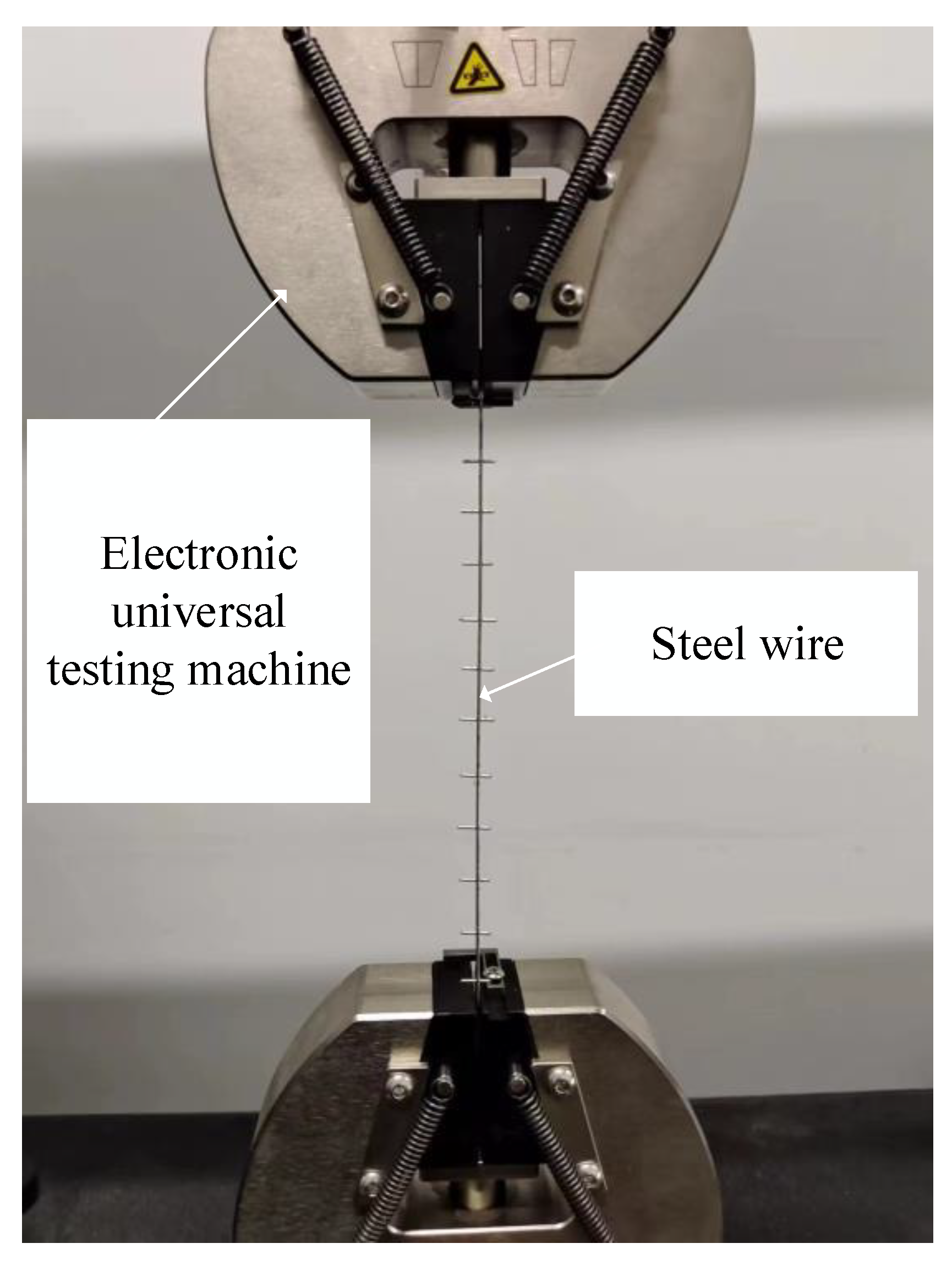
2.1. Material Properties

Q 235 hot-dip galvanized steel wire was utilized for steel wire mesh. A total of 3 steel wires, each with a gauge length of 200 mm, were prepared from the steel wire mesh for uniaxial tensile testing. As shown in Figure 1, the tensile test was conducted using INSTRON 5967 setup (range 500 N, maximum error 2.5 N). Table 1 presents a summary of the test results, including the diameter, yield stress, ultimate stress, and elastic modulus of the steel wires. The average values of the yield stress and ultimate stress were measured as 841.73 MPa and 865.28 MPa, respectively.
The compressive properties of the thermal insulation material were tested by uniaxial compression testing at a loading rate of 4 mm/min with INSTRON 8802 machine (range ±250 kN, maximum error 12.5 N), as shown in Figure 2, according to the Chinese code GB/T 8813-2020 [41]. Cubes of 100 mm (length) × 100 mm (width) × 40 mm (thickness) were utilized for the compression tests. Detailed experimental results are provided in Table 2.

2.2. Test Specimen

The flexural test program consisted of six groups, labeled as 3A01, 3A02, 3A03, 4A01, 4A02, and 4A03, in which the first number represents different loading modes (three-point bending and four-point bending). To minimize the influence of uncertainties on the test results, two specimens were incorporated for each group. As listed in Table 3, in order to study the effects of panel thickness on flexural capacity, the specimen dimensions were designed to be 1400 mm × 600 mm × 40 mm, 1400 mm × 600 mm × 60 mm, and 1400 mm × 600 mm × 80 mm, respectively. Each specimen was composed of two layers of symmetrically arranged steel wire mesh embedded in the insulation panel. The thermal insulation cover of the steel wire mesh was designed to be 0.08 times the thickness of each specimen.

2.3. Test Setup and Instrument
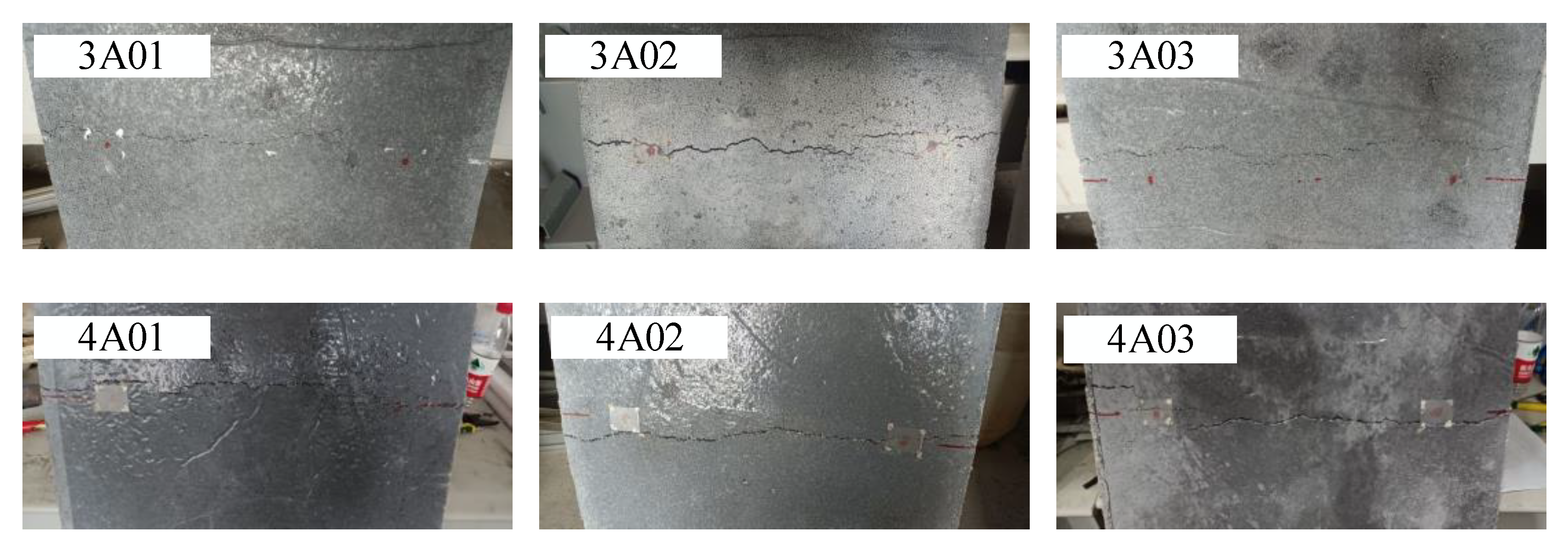
The specimens were subjected to both three-point bending and four-point bending tests. For the four-point bending tests, a pure bending section with a uniform bending moment distribution was present between the loading points, allowing for the assessment of the weak section within the specimens [42,43,44]. The arrangement of the measuring instruments is illustrated in Figure 3, and h represents the thickness of specimens. The support distance for the bending tests was set at 1200 mm. In the 3-point bending tests, the load was applied at the middle point of the topside of the specimens, while in the 4-point bending tests, the load was applied through the spreader beam with a spacing of 600 mm.
According to the Chinese mode GB/T 5486-2008 [45] and JC/T 2493-2018 [46], the test was conducted using a pressure testing machine (range 50 kN, minimum indexing 10 N) through the displacement-controlled loading mode. A layer of roofing felt was set between the supports and the panel. One side was smooth, and the other side could fully contact the rough surface of the specimens. In order to facilitate observation and analysis, the test was performed with graded loading with a loading rate of 10 mm/min, and the specimens were loaded by controlling the displacement to 2–5 mm for each loading step until failure.
In the 3-point bending tests, a linear variable displacement transducer (LVDT) was installed at each of the 2 supports, and 2 LVDTs were arranged in the middle of the span 200 mm away from the center on each side. In the four-point bending tests, in addition to the same positions (the two supports and the middle of the span) as the three-point bending loading, two LVDTs were arranged at the loading points on both sides. The displacement measurements were automatically recorded using LVDTs combined with DH 3816 analysis system for static stress and strain testing.

2.4. Failure Mode

The lower part of the panel experienced tensile stress during the test loading process. Once the bottom of the panel cracked, the tensile stress was primarily borne by the lower steel wire mesh. The failure modes of the six groups of specimens were similar, as shown in Figure 4, consisting of steel wire tensile deformation and panel bottom cracking. The cracks ran through the bottom of the panels in the width direction, and most of the cracks extended to the upper steel wire mesh. Figure 5 depicts the cracks at the bottom of each panel. It can be seen from Figure 6 that in the three-point bending loading, the failure points were consistently located at the mid-span position. Due to the equal bending moments between the two loading points and the absence of shearing force, the failure occurred in the relatively weak section of the specimens. As a result, the bottom of the panel was destroyed at the mid-span and the loading point in the four-point bending loading.

2.5. Load–Deflection Curves

Under the two loading modes, the load–deflection curves of the loading points of the specimens (considering the settlement of pedestals) were obtained until failure, as shown in Figure 7. In the initial loading, the specimens exhibited elasticity, and the load–deflection curves appeared as nearly straight lines. At this time, the insulation material and the steel wire mesh were subjected to synergistic force. When the load increased, the specimens transitioned into the elastic–plastic stage, resulting in a decrease in the slope of the curve. Small cracks appeared at the bottom of the panels at first, and then the crack width expanded as the load increased. After the cracks appeared, the tension was gradually borne by the steel wire mesh. As the load continued to increase until the end of the tests, the specimens reached their ultimate flexural capacity, and the test curve dropped. A comparison of the load–deflection curves between the two loading modes revealed that as the thickness of the panels increased, the distance between the two layers of steel wire mesh also increased accordingly. Consequently, the elastic bending stiffness and flexural capacity of the specimens increased as well. The maximum bending moment of the specimens increased from 1.233 kN·m to 2.415 kN·m, and the elastic bending stiffness increased from 3.85 kN·m2 to 28.90 kN·m2. Detailed experimental results are summarized in Table 4. Notably, a trend was observed in both loading modes: When the thickness increased from 40 mm to 60 mm, little effect on the elastic bending stiffness and maximum bending moment of the specimens was observed. This phenomenon may be attributed to the errors in the pressure at different positions when the instrument was pressurized. Thus, it has fluctuations in the actual thermal insulation cover at different positions with a greater impact observed when the panel thickness was relatively small, as shown in Figure 8.

3. Numerical Analysis

3.1. Establishment of FE Model

3.1.1. Details of FE Model

Numerical investigation was conducted using ABAQUS software to develop finite element (FE) models. The element selection and meshing of the model in this study were shown in Figure 9. In order to improve the calculation efficiency, the solid element with reduced integrated (C3D8R) was employed to simulate the thermal insulation materials and the supports. A beam element with two nodes (B31) was utilized to simulate steel wire mesh, considering the axial strain.
The contact and constraint settings of the four-point bending loading were the same as those of the three-point bending loading, so the three-point bending loading was taken as an example. Figure 10 explains the interaction between the components of the models. The contact using “hard contact” in the normal direction and the “penalty” friction formula in the tangential direction (friction coefficient of 0.8) was adopted between the supports and the steel-wire-enhanced insulation panel. Two layers of steel wire mesh were symmetrically embedded in the insulation panel. Three special points, namely RP-1, RP-2, and RP-3, were set in the top middle of the load adapter and at the bottom middle of the pedestals, respectively, and these points were coupled with their respective planes. The simple support constraints were applied to the two points of the pedestals through RP-1 and RP-2 while the load was applied on RP-3. The mesh sizes of the pedestals, load adapter, and steel wire mesh were set at 5 mm, and the mesh size of the insulation panel was 10 mm.

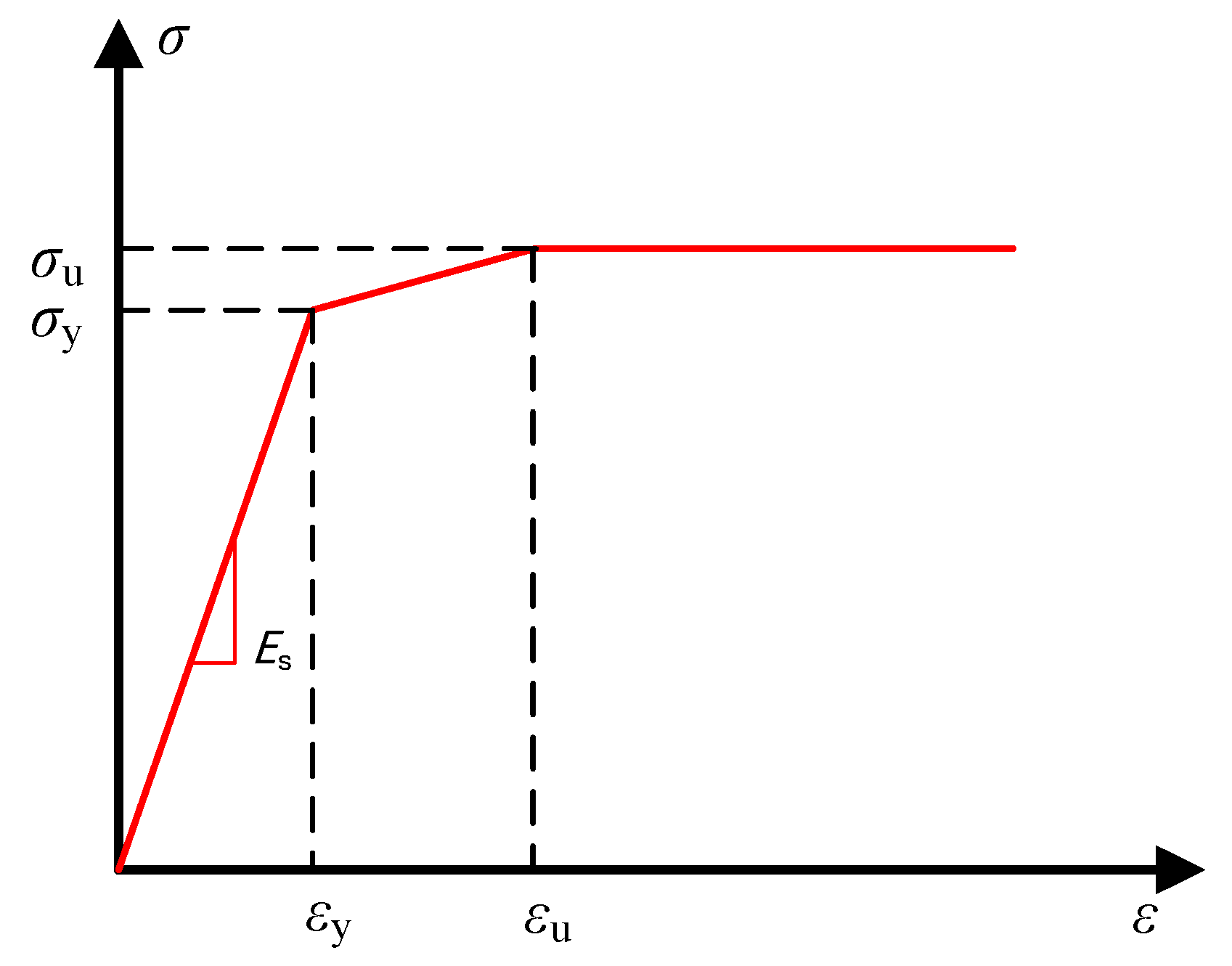
3.1.2. Constitutive Model

The constitutive material model of the steel wire was simplified to the model, as shown in Figure 11, where the elastics modulus, yield strength, and ultimate tensile strength could be obtained from Table 1. The compression constitutive behavior of the thermal insulation material was directly determined from the material property test. εcu and σcu represented the strain and the stress of the highest point on the initial rising curve of the insulation material compression, respectively, while ε0 and σ0 represented the strain and the stress of the lowest point of the first decline of the curve. The tensile data were derived from the tensile test of the polystyrene foam where it was observed that the foam did not break when the stress reached 0.3 MPa, and the strain was 0.02 [47]. This point was conservatively taken as the ultimate stress σtu and ultimate strain εtu. The strain εl and the stress σl represented that the failure of the insulation material was brittle. The specific value is shown in Figure 12.

3.2. FE Model Validation

The validity of the FE model was verified by comparing the experimental load–deflection curves and the simulated load–deflection curves of six groups of specimens, as shown in Figure 13. Table 5 summarizes comparisons between the simulation results and the measured results of the average ultimate bending moment for two specimens in each group. The measured ultimate bending moments of 40 mm thick specimens under 3-point bending loading and 4-point bending loading were found to be 39.0% and 44.6% higher than the simulated ultimate bending moment, respectively. As mentioned above, when the thickness of the insulation panels was small, the actual thermal insulation covers inside the thermal insulation panel fluctuated at different positions, which made the experimental results of the 40 mm thickness specimens larger. The results of the curve comparison experiment showed that the measured ultimate bending moment of 60 mm and 80 mm thickness specimens was only slightly different from the simulated values. The deviation between the measured ultimate flexural capacity and the simulated values of 3A02, 4A02, and 4A03 were within 3% except that the deviation of 3A03 was about 20%. Therefore, despite the specimens not being ideal or entirely standardized, it was reasonable to use this model for predicting the flexural performance of this type of steel-wire-enhanced insulation panel.

3.3. Parametric Analysis

It can be seen from the above that the FE results were in good agreement with the experimental results and the theoretical calculation values when the 3-point bending loading was carried out on the 60 mm thick specimens. Therefore, to better reveal the flexural capacity of this steel-wire-enhanced insulation panel, reference group 3A02 was selected. FE examples were designed to explore the influence of different thermal insulation covers, the square gird spacing of the steel wire mesh, and the steel wire diameter. The simulation results are shown in Figure 14.

3.3.1. Effect of Thermal Insulation Cover

Figure 14a illustrates the remarkable effect of a thermal insulation cover on the flexural capacity of the insulation panel with two layers of symmetrically arranged steel wire mesh embedded inside. The thermal insulation cover refers to the distance between a layer of steel mesh and the nearest edge of the insulation panel, and 0.02 h refers to the thermal insulation cover accounting for 0.02 times the total thickness of the insulation panel. As the thermal insulation cover of the steel wire mesh increased, the distance between the two layers of steel wire mesh decreased, resulting in a reduction in the moment of inertia of the section. Consequently, the stiffness and flexural capacity of the panel decreased. When the thermal insulation cover increased from 0.02 times the panel thickness to 0.30 times the panel thickness, the maximum load that the specimen could withstand decreased from 5.09 kN to 2.28 kN, which was reduced by approximately 55.2%.

3.3.2. Effect of Square Gird Spacing

The square gird spacing of the steel wire mesh also exhibited a significant effect on the flexural capacity of the panel, as shown in Figure 14b. A smaller square gird spacing of the steel wires resulted in a greater influence on the flexural capacity. Specifically, reducing the spacing from 18 mm to 12 mm led to a 40.6% increase in flexural capacity. When the square gird spacing increased from 36 mm to 12 mm, the ultimate load that the panel could withstand increased from 1.868 kN to 4.524 kN. As a result, in practical applications, if the insulation panel needs to have a large flexural capacity, reducing the square gird spacing of the steel mesh could be considered.

3.3.3. Effect of Steel Wire Diameter

Figure 14c illustrates the effect of the steel wire diameter on the flexural capacity of the steel-wire-enhanced insulation panel. The flexural capacity and stiffness of the panels increased significantly when the diameter of the steel wire increased from 1.0 mm to 1.5 mm, but in the range of 1.5 mm to 3.0 mm, the change was not obvious. The tensile steel wire may not yield in the latter specimens, so their flexural capacity was controlled by the compression part of the insulation panel. The maximum load that the panel could withstand was 12.66 kN, and the ultimate bending moment at mid-span was 3.798 kN∙m. Therefore, in the practical application of the insulation panel, for increasing the utilization rate of the material, a diameter of the steel wire larger than 2.0 mm is not recommended, and the flexural capacity could be guaranteed by a 1.5 mm diameter steel wire.

4. Theoretical Stiffness and Flexural Capacity

4.1. Theoretical Elastic Bending Stiffness

During the elastic stage, the bonding between the steel wire and the insulation material was reliable, leading to their synergistic stress. Therefore, the interface slip could be ignored, and the whole section adhered to the assumption of the plane section. When calculating the elastic bending stiffness of the section, the transformed section method was used. This method involved conversion into the same material with the same elastic modulus as the insulation material. Figure 15 depicts the theoretical calculation model for the elastic bending stiffness of the steel-wire-enhanced insulation panel. Among them, b represents the width of the specimens, s represents the square gird spacing of the steel wire mesh, d represents the diameter of the steel wire, as represents the thermal insulation cover, and h0 represents the distance between the two layers of steel wire mesh.
In order to keep the location and resultant of force unchanged, Equations (1) and (2) were satisfied as:
A s σ s = A e σ e
σ s E s = σ e E
where σs and σe represent the stress of the steel wire before and after section conversion, respectively; Es and E represent the elastic modulus of the steel wire and the insulation material, respectively.
The conversion process of the steel wire cross-sectional area can be expressed as:
A e = E s E A s = α · A s
where As represents the actual cross-sectional area of the steel wire, and Ae represents the cross-sectional area of the steel wire after conversion.
The number of the steel wire cross-sectional area on one side after conversion n can be expressed by Equation (4), and α represents the ratio of the elastic modulus of the steel wire Es to the elastic modulus of the insulation material E.
n = α ( b s + 1 )
The moment of inertia of the section near the neutral axis I is expressed in Equation (5).
I = 1 12 b h 3 + n π d 2 32 ( d 2 + 4 h 0 2 )
The elastic bending stiffness of the insulation panel B can be expressed by Equation (6).
B = E I
The theoretical and simulated elastic bending stiffness of the specimens were then compared, as shown in Table 6. The results revealed that the deviations between the theoretical values and the FE values were within 14% in the case of the 3-point bending tests, and the deviations also could be controlled within 22% in the case of the 4-point bending tests. The comparison results showed that the theoretical model with a small deviation could predict the elastic bending stiffness of this steel-wire-enhanced insulation panel.

4.2. Theoretical Flexural Capacity

The neutral axis of the insulation panel moved upward when the specimen reached the ultimate load. Based on the equilibrium equation of axial force, the position of the neutral axis was located within the cross-sectional area of the upper steel wire. Due to the small diameter of the steel wire, it could be approximately considered as being in the middle of the area, as shown in Figure 16. After cracking, the insulation material could not bear the tensile stress, which was borne from the steel wire below the neutral axis, while the compressive stress was borne from the steel wire and insulation material above the neutral axis. It was found that the upper compressive insulation material had a minimal effect on the flexural capacity of the section, accounting for only about 0.2%. For the convenience of calculation, the effect of this part on the flexural capacity was not considered. Equation (7) can be obtained.
M = f y A s h 0
in which fy represents the yield stress of the steel wire, As represents the total cross-sectional area of the lower steel wire, h0 represents the distance between the two layers of the steel wire mesh, and M represents the ultimate bending moment of the section. The theoretical and simulated maximum bending moment of the insulation panel were then compared, as shown in Table 7. The results revealed that the deviations between the theoretical value and the FE model were within 20% under the 2 loading modes, which indicated that the formula was applicable to calculate the flexural capacity of the insulation panel.
In order to assess the practical feasibility of the theoretical calculation formula, a comparison was made for the theoretical ultimate bending moment values Mu,theory, the experimental ultimate bending moment value Mu,e, and the FE simulations of the ultimate bending moment Mu,FE, as shown in Figure 17. The image directly shows that the most discrepancies between the FE formula and the theoretical values were within 20%. It can be seen that the data points of the tests lie above the diagonal line. That indicates the ratio of the experimental ultimate bending moment to the theoretical ultimate bending moment was greater than unity, implying that the theoretical values provide a safe estimate.

5. Discussion and Prospect

The organic–inorganic composite wall panel is an effective approach to address energy dissipation issues and improve living comfort. In recent years, the utilization and promotion of the permanent formwork have emerged as a prevailing trend. In this context, a new type of steel-wire-enhanced insulation panel was proposed. Compared with other forms of thermal insulation panels, it has the following advantages:
(1)
An organic–inorganic composite thermal insulation material was selected and incorporated into the thermal insulation panel, leading to an improvement in the flammability characteristics of traditional EPS. This enhancement enables the panel to achieve A-level non-combustibility.
(2)
The insulation panel was lightweight and easier to transport. The need for procedures such as installing and removing concrete formwork, as well as leveling the surface between the concrete and insulation layer, is eliminated.
(3)
The production process was straightforward, and the size of the steel wire mesh could be conveniently adjusted to meet different flexural capacity requirements.
To verify the actual bending performance of this thermal insulation panel, two bending tests were designed and conducted. The ABAQUS software was employed for numerical simulation, and the results were compared with the experimental values. Based on the test results, it can be observed that the use of steel wire mesh enhanced the flexural capacity of the thermal insulation panels.
This study focuses solely on investigating the flexural capacity of steel-wire-enhanced insulation panels. Further research could explore other mechanical properties, such as compressive strength and shear resistance, evaluating the possibility of similar structures in different applications. In addition, the thermal performance of the steel-wire-enhanced insulation panel is also a major focus of future research.

6. Conclusions

In order to address the issue of excessive self-weight in sandwich insulation panels and to provide a solution for permanent formwork, a novel steel-wire-enhanced insulation was proposed. Due to the lack of research on the mechanical properties of this insulation panel, the flexural performance of steel-wire-enhanced thermal insulation panels was investigated through experimental and finite element (FE) analysis. The conclusions were drawn in the following as:
(1)
At the maximum bending moment of the insulation panel, bottom cracks were observed, primarily in the form of straight single cracks. The structure exhibited significant deformation in the tensile steel wire mesh upon reaching the point of failure. Furthermore, during the destruction of the structure, a few insulation particles near the crack became dislodged.
(2)
The steel-wire-enhanced thermal insulation panel exhibited a certain bending resistance. The stiffness and ultimate flexural capacity of the panel did not change significantly when the thickness of the panel increased from 40 mm to 60 mm. The maximum bending moment that the section could withstand was basically between 1.2–1.4 kN∙m. When the thickness of the panel was 80 mm, the maximum bending moment and elastic bending stiffness could reach 2.415 kN∙m and 28.90 kN·m2 individually.
(3)
The FE model that could reflect the flexural capacity of the embedded wire mesh insulation panel to a certain extent was obtained. The influence of different size parameters on the stiffness and flexural capacity of the panel was examined through the FE models. It was observed that the insulation cover had a significant effect on the flexural capacity. When the thermal insulation cover increased from 0.02 times the panel thickness to 0.30 times the panel thickness, the maximum load that the panel could withstand was reduced by approximately 55.2%. When the steel wire spacing and steel wire diameter were large, the flexural capacity had little effect.
(4)
By employing the transformed section method and assuming the plane section assumption, a theoretical formula for the elastic bending stiffness was derived. The influence of the thermal insulation material on the bearing capacity was found to be approximately 0.2%; therefore, only the contribution of the two-layer steel wire mesh was considered. The suitability of theoretical formulas in predicting the elastic stiffness and flexural capacity of the embedded double-layer steel wire mesh insulation panel was evaluated by comparing them with the FE results. The analysis showed that the deviation between the theoretical values and the FE results was mostly controlled within 20%. This deviation may be attributed to the omission of the transverse steel wire in theoretical calculation. Moreover, the experimental values of the ultimate bending moment exceeded the theoretical calculations, ensuring the safety of the theoretical predictions.

Author Contributions

Conceptualization, J.J. and J.T.; methodology, J.J. and J.T.; software, L.X. and E.Z.; validation, L.X., E.Z. and J.J.; formal analysis, J.J. and J.T.; investigation, J.J. and J.T.; resources, J.J. and J.T.; data curation, J.J. and J.T.; writing—original draft preparation, L.X.; writing—review and editing, J.T., E.Z. and J.H.; supervision, J.T. and J.H.; project administration, J.T.; funding acquisition, J.T. All authors have read and agreed to the published version of the manuscript.

Funding

This study has been supported by research grants from the National Natural Science Foundation of China (52108180) and the Zhejiang Provincial Natural Science Foundation of China (LQ21E080018).

Data Availability Statement

All data of this study are available upon reasonable request to the corresponding author.

Acknowledgments

The work of member testing accomplished by Yunzhong Cao is greatly appreciated.

Conflicts of Interest

The authors declare that they have no known competing financial interest or personal relationships that could have appeared to influence the work reported in this paper.

References

  1. Ling, H.J.; Xiong, H.R.; Yu, A.N.; Yuan, K.L.; Li, J. Statistical survey of the degradation of finishing coating for external thermal insulation composite systems in walls. New Build. Mater. 2018, 45, 114–118. [Google Scholar]
  2. Pan, P.; He, Z.; Wang, H.; Kang, Y. Experimental investigation of C-shaped glass-fiber-reinforced polymer connectors for sandwich insulation wall panels. Eng. Struct. 2022, 250, 113462. [Google Scholar] [CrossRef]
  3. Jelle, B.P. Traditional, state-of-the-art and future thermal building insulation materials and solutions—Properties, requirements and possibilities. Energy Build. 2011, 43, 2549–2563. [Google Scholar] [CrossRef] [Green Version]
  4. Yoo, J.; Chang, S.J.; Yang, S.; Wi, S.; Kim, Y.U.; Kim, S. Performance of the hygrothermal behavior of the CIT wall using different types of insulation; XPS, PF board and glass wool. Case Stud. Therm. Eng. 2021, 24, 100846. [Google Scholar] [CrossRef]
  5. Guo, W.; Chen, S.; Liang, F. Ultra-light-weight, anti-flammable and water-proof cellulosic aerogels for thermal insulation applications. Int. J. Biol. Macromol. 2023, 246, 125343. [Google Scholar] [CrossRef]
  6. Lakreb, N.; Sen, U.; Toussaint, E.; Amziane, S.; Djakab, E.; Pereira, H. Physical properties and thermal conductivity of cork-based sandwich panels for building insulation. Constr. Build. Mater. 2023, 368, 130420. [Google Scholar] [CrossRef]
  7. Shao, H.; Xu, H.; Zhu, W.; Wu, H.; Liu, Z. Thermal-mechanical properties of polystyrene insulation board under defect condition and their influence on lining structure of conveyance channel. Cold Reg. Sci. Technol. 2023, 206, 103752. [Google Scholar] [CrossRef]
  8. Tai, Q.; Chen, L.; Song, L.; Nie, S.; Hu, Y.; Yuen, R.K.K. Preparation and thermal properties of a novel flame retardant copolymer. Polym. Degrad. Stab. 2010, 95, 830–836. [Google Scholar] [CrossRef]
  9. Ge, X.G.; He, J.; Liu, W.; Liu, J.J.; Zhang, Z.R.; Yin, Z.L.; Zhang, Y. Fire effluents hazard and thermal properties of organic thermal insulation materials. New Build. Mater. 2018, 45, 1–4. [Google Scholar]
  10. Ding, C.; Xue, K.; Cui, H. Research on fire resistance of silica fume insulation mortar. J. Mater. Res. Technol. 2023, 25, 1273–1288. [Google Scholar] [CrossRef]
  11. Wang, Z.; Huang, Z.; Yang, T. Silica coated expanded polystyrene/cement composites with improved fire resistance, smoke suppression and mechanical strength. Mater. Chem. Phys. 2020, 240, 122190. [Google Scholar] [CrossRef]
  12. Tao, Y.; Mahendran, M. Fire tests and thermal analyses of LSF walls insulated with silica aerogel fibreglass blanket. Fire Saf. J. 2021, 122, 103352. [Google Scholar] [CrossRef]
  13. Lakatos, Á.; Kalmár, F. Investigation of thickness and density dependence of thermal conductivity of expanded polystyrene insulation materials. Mater. Struct. 2013, 46, 1101–1105. [Google Scholar] [CrossRef] [Green Version]
  14. Abina, A.; Puc, U.; Jeglič, A.; Zidanšek, A. Structural analysis of insulating polymer foams with terahertz spectroscopy and imaging. Polym. Test 2013, 32, 739–747. [Google Scholar] [CrossRef]
  15. Huang, J.; Zhao, Z.; Chen, T. Preparation of highly dispersed expandable graphite/polystyrene composite foam via suspension polymerization with enhanced fire retardation. Carbon 2019, 146, 503–512. [Google Scholar] [CrossRef]
  16. Shi, Y.; Liu, C.; Fu, L.; Yang, F.; Lv, Y.; Yu, B. Hierarchical assembly of polystyrene/graphitic carbon nitride/reduced graphene oxide nanocomposites toward high fire safety. Compos. Part B Eng. 2019, 179, 107541. [Google Scholar] [CrossRef]
  17. Park, H.S.; Kim, Y.; Oh, B.K.; Cho, T. Compressive properties of graphite-embedded expanded polystyrene for vibroacoustic engineering applications. Compos. Part B Eng. 2016, 93, 252–264. [Google Scholar] [CrossRef]
  18. Zhou, J.; Wang, H.H.; Tian, C.Y.; Chang, W.H.; Li, W.Y. Study on design method of steel-bars truss decks with permanent bottom form. Build. Struct. 2022, 52, 1454–1458. [Google Scholar]
  19. Wang, L.C.; Yin, S.P.; Zhu, J.Y.; Huang, Z.H. Flexural performance of BFRP reinforced seawater sea-sand concrete beams with TRE SIP forms under a dry-wet environment. Appl. Ocean Res. 2023, 130, 103442. [Google Scholar] [CrossRef]
  20. Zeng, J.J.; Chen, S.P.; Peng, K.D.; Dai, J.G. Novel FRP micro-bar reinforced UHPC permanent formwork for circular columns: Concept and compressive behavior. Compos. Struct. 2022, 285, 115268. [Google Scholar] [CrossRef]
  21. Li, S.C.; Yin, S.P. Research on the mechanical properties of assembled TRC permanent formwork composite columns. Eng. Struct. 2021, 247, 113105. [Google Scholar] [CrossRef]
  22. Daskiran, M.M.; Daskiran, E.G.; Gencoglu, M. Seismic performance of PVA textile cementitious composites used as permanent formwork in full-scale circular RC columns. Structures 2022, 36, 445–462. [Google Scholar] [CrossRef]
  23. Zhang, P.; Xu, F.; Liu, Y.; Ahmed Sheikh, S. Shear behaviour of composite beams with permanent UHPC formwork and high-strength steel rebar. Constr. Build. Mater. 2022, 352, 128951. [Google Scholar] [CrossRef]
  24. Wang, Z.Y.; Liang, X.W.; Wang, Y.; Zhai, T.W. Experimental and theoretical investigations on the flexural behavior of RC slabs with steel-PVA hybrid fiber reinforced cementitious composite (HFRCC) permanent formwork. Case Stud. Constr. Mater. 2022, 17, e01432. [Google Scholar] [CrossRef]
  25. Egbon, B.; Tomlinson, D. Experimental investigation of longitudinal shear transfer in insulated concrete wall panels with notched insulation. J. Build. Eng. 2021, 43, 103173. [Google Scholar] [CrossRef]
  26. He, Z.; Pan, P.; Xiao, G.; Shen, S.; Ren, J. Test and analysis on axial performances of GFRP restraint connectors for sandwich insulation wall panels. J. Build. Eng. 2022, 45, 103457. [Google Scholar] [CrossRef]
  27. Tong, J.Z.; Wu, R.M.; Xu, Z.Y.; Guo, Y.L. Subassemblage tests on seismic behavior of double-corrugated-plate shear walls. Eng. Struct. 2023, 276, 115341. [Google Scholar] [CrossRef]
  28. Tong, J.; Wu, R.; Wang, L. Experimental and numerical investigations on seismic behavior of stiffened corrugated steel plate shear walls. Earthq. Eng. Struct. Dyn. 2023. [Google Scholar] [CrossRef]
  29. Zhang, J.W.; Tong, J.Z.; Yu, C.Q.; Tong, G.S.; Chen, M.; Zhang, L.; Yang, S.L. Experimental evaluation on seismic performance of multi-celled corrugated-plate CFST walls. J. Constr. Steel Res. 2023, 201, 107743. [Google Scholar] [CrossRef]
  30. Zhou, S.M.; Tong, J.Z.; Tong, G.S.; Xu, Q.B. Testing on global stability performance of multi-celled CFST walls with three simply-supported edges. Eng. Struct. 2023, 291, 116478. [Google Scholar] [CrossRef]
  31. Hou, C.; Han, L.H.; Zhao, X.L. Concrete-filled circular steel tubes subjected to local bearing force: Experiments. J. Constr. Steel Res. 2013, 83, 90–104. [Google Scholar] [CrossRef]
  32. Hou, H.; Ji, K.; Wang, W.; Qu, B.; Fang, M.; Qiu, C. Flexural behavior of precast insulated sandwich wall panels: Full-scale tests and design implications. Eng. Struct. 2019, 180, 750–761. [Google Scholar] [CrossRef]
  33. Tomlinson, D.; Fam, A. Analytical approach to flexural response of partially composite insulated concrete sandwich walls used for cladding. Eng. Struct. 2016, 122, 251–266. [Google Scholar] [CrossRef]
  34. Arun, S.A.; Hemalatha, G.; Hemalatha, G.; Joel, S.J.; Jemimah, C.M. Exploring the impact of eps incorporation on insulated concrete form (ICF) wall panels under axial compression and flexure. J. King Saud Univ.-Eng. Sci. 2022. [Google Scholar] [CrossRef]
  35. Zhang, T.; Yuan, J.; Pang, H. UHPC-XPS insulation composite board reinforced by glass fiber mesh: Effect of structural design on the heat transfer, mechanical properties and impact resistance. J. Build. Eng. 2023, 75, 106935. [Google Scholar] [CrossRef]
  36. Liu, M.; Wang, L.; Ma, G.; Li, W.; Zhou, Y. U-type steel wire mesh for the flexural performance enhancement of 3D printed concrete: A novel reinforcing approach. Mater. Lett. 2023, 331, 133429. [Google Scholar] [CrossRef]
  37. Banerjee, S.; Nayak, S.; Das, S. Enhancing the flexural behaviour of masonry wallet using PP band and steel wire mesh. Constr. Build. Mater. 2019, 194, 179–191. [Google Scholar] [CrossRef]
  38. Qeshta, I.M.I.; Shafigh, P.; Jumaat, M.Z.; Abdulla, A.I.; Ibrahim, Z.; Alengaram, U.J. The use of wire mesh–epoxy composite for enhancing the flexural performance of concrete beams. Mater. Des. 2014, 60, 250–259. [Google Scholar] [CrossRef]
  39. Li, K.; Wei, Y.; Li, Y.; Li, Z.; Zhu, J. Flexural behavior of reinforced concrete beams strengthened with high-strength stainless steel wire rope meshes reinforced ECC. Constr. Build. Mater. 2023, 362, 129627. [Google Scholar] [CrossRef]
  40. Banerjee, S.; Nayak, S.; Das, S. Shear and flexural behaviour of unreinforced masonry wallets with steel wire mesh. J. Build. Eng. 2020, 30, 101254. [Google Scholar] [CrossRef]
  41. GB/T 8813; Rigid Cellular Plastics-Determination of Compression Properties. Certification and Accreditation Administration: Beijing, China, 2020.
  42. Tong, J.Z.; Chen, Y.L.; Li, Q.H.; Chen, T.Q.; Gao, W. Experimental and Numerical Study of Transversal Flexural Behavior on Steel Ultrahigh-Toughness Cementitious Composite Bridge Decks. J. Bridge Eng. 2023, 28, 04023044. [Google Scholar] [CrossRef]
  43. Tong, J.Z.; Chen, Y.L.; Li, Q.H.; Xu, S.L.; Zeng, T.; Gao, W. Experimental study on flexural performance of steel-UHTCC composite bridge decks considering different shear connection degrees. Eng. Struct. 2023, 281, 115738. [Google Scholar] [CrossRef]
  44. Wang, G.Z.; Tong, J.Z.; Li, Q.H.; Xu, S.L.; Dai, J.B. Flexural Performance and Design of Steel-UHTCC Composite Bridge Decks with Different Composite Degrees under Hogging Moments. J. Struct. Eng. 2023, 149, 04023023. [Google Scholar] [CrossRef]
  45. GB/T 5486; Test Methods for Inorganic Rigid Thermal Insulation. Standards Press of China: Beijing, China, 2008.
  46. JC/T 2493; Thermal Insulation Free from Demolition Template for Buildings. China Building Materials Press: Beijing, China, 2018.
  47. Tang, N.; Lei, D.; Huang, D.; Xiao, R. Mechanical performance of polystyrene foam (EPS): Experimental and numerical analysis. Polym. Test 2019, 73, 359–365. [Google Scholar] [CrossRef]
Figure 1. Steel wire tensile test.
Buildings 13 01978 g001
Figure 2. Insulation material compression test.
Buildings 13 01978 g002
Figure 3. Diagram of two modes of bending test (unit: mm): (a) three-point bending test; (b) four-point bending test.
Buildings 13 01978 g003
Figure 4. Failure modes of the specimens.
Buildings 13 01978 g004
Figure 5. Bottom damage.
Buildings 13 01978 g005
Figure 6. Damage position of specimens.
Buildings 13 01978 g006
Figure 7. Load–deflection curves of the specimens: (a) three-point loading mode; (b) four-point loading mode.
Buildings 13 01978 g007
Figure 8. Actual steel wire mesh position.
Buildings 13 01978 g008
Figure 9. FE models of specimens.
Buildings 13 01978 g009
Figure 10. The interaction of each part.
Buildings 13 01978 g010
Figure 11. Constitutive model of steel wire.
Buildings 13 01978 g011
Figure 12. Constitutive model of insulation material.
Buildings 13 01978 g012
Figure 13. Comparison of load–deflection curves between FE models and tests.
Buildings 13 01978 g013
Figure 14. Parametric analysis: (a) effect of thermal insulation cover; (b) effect of gird spacing; (c) effect of steel wire diameter.
Buildings 13 01978 g014
Figure 15. Theoretical calculation model.
Buildings 13 01978 g015
Figure 16. Section force diagram.
Buildings 13 01978 g016
Figure 17. Accuracy of theoretical formula for ultimate flexural resistance.
Buildings 13 01978 g017
Table 1. Properties of steel wires.
CouponDiameter (mm)Yield Stress (MPa)Ultimate Stress (MPa)Elastic Modulus (GPa)
10.81858.80861.28231.757
2821.12868.81
3845.28865.74
Table 2. Properties of insulation material.
Compression Area
A0 (mm2)
Thickness
h0 (mm)
Maximum Force
Fm (kN)
Elastic Force
Fe (kN)
Elastic Modulus
E (MPa)
Compressive Strength
σ m (MPa)
10,000404.4593.9672.340.446
Table 3. Actual parameters of the specimens.
SpecimenLength
L (mm)
Width
b (mm)
Thickness
h (mm)
Thermal Insulation Covers
as (mm)
3A01-a1400600.042.53.40
3A01-b1400595.041.53.32
3A02-a1400600.060.54.84
3A02-b1400597.061.54.92
3A03-a1400600.085.06.80
3A03-b1400594.086.06.88
4A01-a1400600.043.53.48
4A01-b1400595.044.03.52
4A02-a1400600.063.25.06
4A02-b1400600.062.55.00
4A03-a1400600.082.06.56
4A03-b1400600.082.56.60
Table 4. Specific experimental results.
SpecimenMaximum Load
F (kN)
Maximum Bending Moment
Me (kN‧m)
Bending Stiffness
Be (kN‧m2)
3A01-a4.111.2335.11
3A01-b3.921.1763.85
3A02-a4.221.2665.93
3A02-b4.551.3658.36
3A03-a8.052.41526.15
3A03-b7.852.35528.90
4A01-a8.261.2396.88
4A01-b9.131.3707.14
4A02-a8.981.3478.73
4A02-b9.131.3708.51
4A03-a13.091.96423.23
4A03-b12.111.81718.72
Table 5. Comparison results between FE models and tests.
SpecimenBending Moment (kN‧m)Error *
Experimental Results Mu,eFE Results Mu,FE
3A011.2050.86739.0%
3A021.3161.357−3.0%
3A032.3851.96521.4%
4A011.3040.90244.6%
4A021.3581.3550.2%
4A031.8901.8522.0%
* Error = (Mu,eMu,FE)/Mu,FE.
Table 6. Comparison between theoretical and FE model values of bending stiffness.
SpecimenElastic Bending Stiffness (kN‧m2)Error *
Theoretical Results Bu,theoryFE Results Bu,FE
3A014.043.5713.2%
3A028.808.197.5%
3A0317.8815.7913.2%
4A014.405.28−16.7%
4A029.3912.02−21.9%
4A0316.5520.82−20.5%
* Error = (Bu,theoryBu,FE)/Bu,FE.
Table 7. Comparison between theoretical and FE model values of bending moment.
SpecimenBending Moment (kN‧m)Error *
Theoretical Results Mu,theoryFE Results Mu,FE
3A010.7770.867−10.4%
3A021.3161.357−16.7%
3A031.5811.965−19.5%
4A010.8100.902−10.2%
4A021.1681.355−13.8%
4A031.5281.852−17.5%
* Error = (Mu,theoryMu,FE)/Mu,FE.
Disclaimer/Publisher’s Note: The statements, opinions and data contained in all publications are solely those of the individual author(s) and contributor(s) and not of MDPI and/or the editor(s). MDPI and/or the editor(s) disclaim responsibility for any injury to people or property resulting from any ideas, methods, instructions or products referred to in the content.

