Article

Innovative Equivalent Elastic Modulus Based Stress Calculation Methodology for Reinforced Concrete Columns

Department of Civil Engineering, School of Engineering and Natural Sciences, Istanbul Medipol University, 34810 Istanbul, Türkiye
*
Author to whom correspondence should be addressed.
Buildings 2023, 13(8), 1962; https://doi.org/10.3390/buildings13081962
Submission received: 7 July 2023 / Revised: 26 July 2023 / Accepted: 28 July 2023 / Published: 1 August 2023
(This article belongs to the Section Building Materials, and Repair & Renovation)

Abstract

:
The combination of linearity and elasticity assumptions provides classical calculation procedures for the reinforced concrete (RC) columns and beams against internal and external seismic loads. In these calculation procedures, the elasticity modulus of the concrete is taken into account by ignoring the steel reinforcement due to its small area percentage in the total cross-section area. This paper presents an innovative column stress calculation procedure considering the concrete–steel composition as the equivalent elastic modulus based on the classical Hooke’s Law. This methodology takes into consideration also the elastic modulus of the steel, providing a reduction in the factor of safety. The application of the proposed method is presented for a series of RC column cross-section areas. It is observed that the proposed methodology leads to elastic modulus improvement of 6% to 27% compared to conventional calculations. The necessary flow chart for the execution of the proposed process steps and accordingly developed MATLAB program are provided for the application.

1. Introduction

In general, reinforced concrete (RC) columns resist greater strength than traditionally computed results based on the conventional elastic, uniform and linear stress distribution according to Hooke’s Law. For all uncertainty types that enter any RC beam calculation, the elastic method is a satisfactory solution for present-day conditions [1]. Concrete–steel composite structures have developed rapidly since the 1950s due to their superior performance and material advantage [2]. Generally, concrete and steel joint behaviour in an RC column and beam is unlike material science, where the direct rule of mixtures is a weighted average. Such an approach provides a theoretical basis for elastic modulus, ultimate tensile stress, thermal conductivity, and electric conductivity [3]. Recently, the rehabilitation, retrofitting, and strengthening of structures have been endorsed by many researchers as more sustainable solutions than the demolition and reconstruction of the whole structure [4].
Generally, the elastic cross-section properties for the service load-level designs are higher than those used to determine the required strengths [5]. Elastic analyses are used for many purposes in the design of RC structures. In common civil engineering RC column and beam strength calculations, only concrete elasticity modulus is taken into account, and steel reinforcement contribution is not taken into account. According to the simplest linear and elastic models, RC cross-sections remain planar under steel and concrete elastic joint behaviour subject to external loads. It has been well-known for many years that a “safety factor” (SF) is applied to increase the reliability of deterministic formulation results to stay on the safe side. Thus, the numerical results out of relevant methodological calculations end up with underestimation, and therefore, the results are increased by multiplication with a safety factor (SF) that is more than one. Therefore, RC structural elements deserve objectively finer innovative methodologic calculations to reduce the impact of SF. In practical applications, the importance of such a factor arises because of the heterogeneous and complex behaviour of the concrete and steel material contacts. The cross-section strength in an RC column should be computed by taking into account both concrete and steel bar joint functions in an adjustable way.
The cross-section geometry can be in circular, rectangular, square, hexagonal, etc., forms in addition to the position of steel bars and their areal and elastic modulus amounts. For example, in the literature, especially in stiffness calculations, some works take the ratio of elastic modulus of concrete and steel, where stiffness is defined as the elastic modulus multiplied by the moment of inertia [6]. Such an elastic modulus ratio concept is important not only in common structural elements but also in prestressed, jacketed, and encased concretes [4,5]. It is involved in all expressions related to the mass or weight of the members, axial, and flexural actions, deformations, strains, and stresses [6]. The importance of the elastic modulus ratio will be explained later in this paper based on a set of new formulations.
In recent years, there have been several works based on the national code determination of elastic modulus (E) combination with the moment of inertia (I) just for stiffness calculation leading to deformation studies [7,8,9,10]. Overwhelmingly in the literature, rectangular cross-sections are adapted for formulations, whereas Ehsani and Alameddine [11], and Sigmon and Ahmad [12] considered loads on circular cross-sections for stiffness calculations. For example, Bonet et al. [13] proposed a conservative column formula according to the ACI-318-02 [14] standard. Bonet et al. [15] proposed a new approach for stiffness calculation for RC columns for any cross-section shapes under the effect of axial load. The calculations are made based on concrete and steel elastic modulus, young modulus, mean compressive strength of concrete, and moment of inertia, where steel and concrete elastic modulus are obtained from the Euro Code 2 [16]. The behaviour of cross-sections is represented by elastic rigidities in frame elastic analyses, which define the stiffness of cross-sections in various deformation modes, such as the axial stiffness, the flexural stiffness, the shear stiffness, and the torsional stiffness. For moment frame systems, the dominant deformation mode is typically bending; thus, flexural stiffness is of prime importance [17].
Cai et al. [18] presented a new unified design equation for estimating the axial compressive strength of square and rectangular concrete-filled steel tubular (CFST) short columns. The proposed design equation offers several advantages over existing formulations, including faster and more convenient estimation, elimination of section slenderness calculations, and extended material strength limits for concrete infill and steel tubes. Nocera et al. [19] developed probabilistic models to estimate the Strength Reduction Factor (SRF) and Elastic Modulus Reduction Factor (ERF) of rubberized concrete, considering various mix design variables, and three types of rubber aggregates using a Bayesian approach with Markov Chain Monte Carlo simulation. The proposed probabilistic models are employed to assess the reliability of rubberized RC structures, including a column and a one-way slab subjected to compressive axial force and distributed load, respectively. Khalel and Khan [20] focused on the selection and impact of fibre reinforcement in fibre-reinforced cementitious composites. They proposed a model that predicts compressive and flexural strengths based on input parameters such as fibre shape, type, length, and percentage. Their model assumes the elastic modulus validation using statistical tools and demonstrates accuracy, with errors less than 6% for compressive strength and 15% for flexural strength. Gandomi et al. [21] used a multi expression programming procedure as a new design calculation by considering the elastic modulus of concrete. For greater sustainability in construction, Chen et al. [22] proposed popular coarse recycled aggregate concrete (RAC) as a replacement for natural aggregate concrete (NAC) structures. Felix et al. [23] have used a machine learning procedure to estimate the elastic modulus of concrete through regression and artificial neural network (ANN) procedures. Although these references dealt with the elasticity modulus of concrete, there is no mention of the contribution of the steel reinforcement support in the RC cross-section strength computations as proposed in this paper. RC columns are among the most common vertical load-bearing components in bridges and building structures, which provide an increase in service loads and damages caused by earthquakes or due to exposure to additional physical loads in harsh environments, where strengthening, rehabilitation, and retrofitting are often demanded to restore and enhance their performances.
The main purpose of this paper is to propose a new calculation approach for the RC column strength calculation by considering not only concrete elastic modulus but also supportive steel reinforcement elasticity modulus joint contributions. The equivalent elastic modulus equation is derived for the integrated behavioural action of concrete and steel. The application of the methodology is presented for a set of circular, rectangular, and square-column cross-sectional areas coupled with a set of concrete quality classes. The comparison of the classical and newly proposed method results shows 6% to 27% improvements.

2. Composite Elasticity Model

In RC structures, stress, strain, and deformation activities are concerned with the structural element cross-sectional areas subject to internal and external loadings. Although non-linear deformation is related to the same cross-sectional area, it has not been considered herein because it is more related to the stiffness property of the structural element. Commonly it is well-known that stress is equal to force divided by the total cross-sectional area, irrespective of concrete and steel areas. In this paper, the reverse operation is also used to calculate the stress on concrete and steel interactively to reach the same force after the calculation of the equivalent elasticity modulus for the joint behaviour of concrete and steel bars.
In general, an RC cross-section has few properties for strength calculations, such as the moment of inertia of the cross-section and the elasticity modulus of concrete. Cross-section properties should include physical quantities like steel area percentage in the total cross-section area and elastic modulus of steel bars, as they are the most-ignored elements.
The research progress in RC needs to understand the actual areal behaviour of structure cross-section as the composite material form. There are unprecedented developments in RC elements’ analysis based on the assumptions of linearity and elasticity concepts in Hooke’s Law, where only concrete elastic modulus is taken into account. However, such an approach is not confirmed with facts because steel bar contribution is not considered. Steel is an elastic material like concrete, and the inclusion of steel strength in the calculations provides an additional ability for refined results that reduces the multiplicative SF amount.
Inside the cross-section of a column, as for the classical structural engineering calculations, concrete and steel are subjected to the same stress, whatever the cross-section areal composition of these materials. To explain this concept, let us consider a square column, as in Figure 1.
The following points are important for proposing a new formulation for concrete and steel joint behaviour.
  • The total cross-sectional area, AT, is composed of a concrete area, AC, and the steel bars’ area, AS;
  • The steel bars’ area, AS, or the concrete area, AC, are expressible as follows;
    AS = AT − AC
    AC = AT – AS
  • The total area can be calculatable provided that the cross-section shape of the column is given as circular, rectangular, or square with two-dimensional measures;
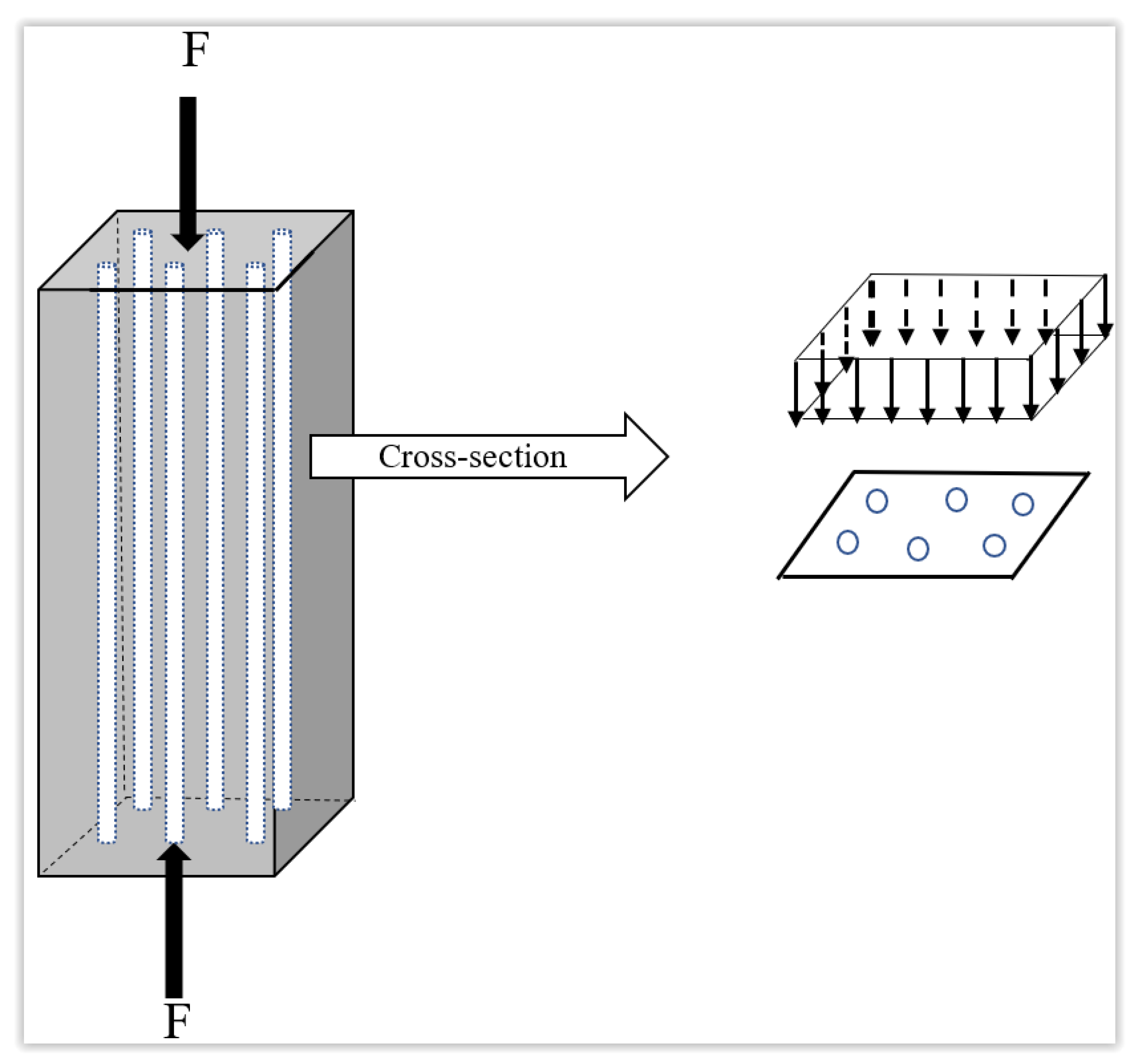
  • As for the stress distribution, concrete and steel areas are subjected to the same stress amount;
  • As for the strain, both materials will react equally, where concrete will be a dependent material to steel or vice versa. Thus, each material will have the same strain under the force, F, in a column (see Figure 1).
In the light of these points, it is possible to write stress expressions for each element from Hooke’s Law, in general, as a well-known expression between stress, σ, and strain, ε, with a mediator of elastic modulus, E as,
σ = E   ε
The versions of this expression can be written for the elastic modulus of concrete and steel materials (concrete, EC, steel, ES) separately as follows:
σ = E C   ε
and
σ = E S   ε
These equations can be transformed into forces (concrete, FC, steel, FS) by taking into consideration the stress and the cross-sectional areas.
F C = A C   E C   ε
and
F S = A S   E S   ε
According to the static mechanism, action and reaction forces balance each other leading to the following expression:
F = A C   E C   ε + A S   E S   ε
The crunch point of the newly proposed methodology is the consideration of equivalent elastic modulus, EE, which allows writing the following expression similarly to the previous equations:
A T   E E   ε = A C   E C   ε + A S   E S   ε
Since all cases are under the same stress and strain, this expression takes the following simple form:
A T   E E = A C   E C + A S   E S
Division of both sides by total area, AT, yields:
E E = A C A T   E C + A S A T   E S
The ratios on the right-hand side imply areal percentages of concrete, APC, and steel, ASC, respectively. Then succinctly, the last expression can be written as:
E E = A PC   E C + A PS   E S
Finally, according to this expression, Hooke’s Law takes the following newly modified form as:
σ = ( A PC   E C + A PS   E S )   ε
If only the concrete cross-sectional area is taken into consideration as in the classical civil engineering calculations, then Equation (13) reduces to Equation (4) provided that APS is equal to zero, then APC is equal to 1. The relative improvement percentage, RIP, between the last expression becomes after a simple algebraic calculation as:
R IP = A PC + A PS   E S E C 1
With elasticity modulus ratios, ER = ES/EC, the final form of the relative improvement percentage, RIP, becomes as follows:
R IP = A PC + A PS   E R 1

3. Application and Results

In light of what has been explained in the previous sections, the application of the proposed methodology is presented for a set of column cross-sectional areas in different forms (see Figure 2). Concrete and steel cross-sectional area (AC and AS), total area (AT), and rebar ratio (ρ) values are calculated and presented in Table 1.
Additionally, elastic modulus values are given in Table 2 for a set of concrete and steel quality classes for newly proposed methodological calculations in light of the equations presented in the previous section.
The following MATLAB program (Figure 3) is written by the authors for automatic computations of equivalent elastic modulus and relative improvement percentages based on the relevant numerical values given in Figure 2 and Table 1 and Table 2.
The essence of this program can be described in the Figure 4 flowchart by integrating the concrete qualities and steel elastic modulus application on the 20 different types of cross-section areas given in Figure 2 and Table 1.
In Table 3, the equivalent elastic modulus values appear as outputs after the aforementioned MATLAB program execution.
The changes of equivalent elastic modulus with the cross-section area type are shown in Figure 5.
Each cross-section number on the horizontal axis represents the total cross-section area, including concrete and steel. Another computation output of the program yields the relative improvement percentages of the newly proposed methodology compared with the classical Hooke’s Law calculation of the stress without steel reinforcements (see Equation (15)), and the results are presented in Table 4. It indicates the improvement percentages of the new methodological calculation over the classical engineering calculation.
Figure 6 shows the relative improvement percentage change depending on the concrete quality with respect to the cross-sectional area. According to the proposed methodology in this paper, the least error percentage is with section number 20 coupled with concrete quality C50. The maximum relative improvement percentage is with the cross-section area in number 17 (slightly rectangular) and associated with concrete quality C16. Comparison of this last figure with the previous one indicates the same minimum and maximum equivalent elastic modulus for the same cross-sectional and concrete quality categories.

4. Discussion

According to Hooke’s Law, the classical column stress calculation does not consider the steel bars’ contribution. Although steel reinforcement has a comparatively small area within the total cross-section area, its very high elastic modulus adds an important contribution to the RC column strength. The proposed methodology considers steel bar areas’ important contribution to the overall stress calculation because the elastic modulus of steel is higher than concrete. In light of the proposed methodology, the following points are worth considering in comparison to the classical linear Hooke’s Law calculation:
  • The applications indicate that the relative improvement percentages over the classical Hooke’s Law calculations vary between 6% and 27% (see Figure 6). The steel reinforcement consideration is the main improvement factor, together with areal and elastic modulus contributions of various cross-section shapes with different concrete qualities;
  • As the concrete quality increases (from C16 to C50), the improvement percentage also increases, and other concrete quality improvement percentages are confined between these two concrete qualities;
  • The minimum percentage improvement is with a square cross-sectional area coupled with C50, whereas the maximum is with a slightly rectangular cross-sectional area coupled with C16 concrete quality;
  • Increasing the relative improvement percentage on behalf of the steel is possible by increasing the steel area percentage. Thus, there is an optimum reinforcement possibility for the column design. In such optimization work, the budget (economic) conditions also play a restrictive role;
  • Steel reinforcement contribution calculations augment the strength of the column, and thus some part of the “safety factor” can be reduced according to the proposed methodological calculation. With the newly proposed methodology, the SF amount becomes closer to 1.
It is recommended that the contribution of the steel elastic modulus and areal extensions should be taken into account in future RC strength calculations of beams, slabs, shear walls, arches, and bridges. In addition, the crushing and buckling behaviours of RC columns with the contribution of the steel elastic modulus can be studied as a future work by examining the short and long columns.

5. Conclusions

In classical reinforced concrete (RC) calculations, steel reinforcement area and elastic modulus are overlooked. Thus, classical RC calculations yield under-estimation; therefore, the computation results are multiplied by a safety factor with a value slightly bigger than one. This study provides a new methodology for refined calculations in RC columns by integrating steel reinforcement elastic modulus and cross-section area contributions. The necessary formulations are derived in the forms of equivalent elastic modulus and relative improvement percentages. The proposed methodology provides finer calculations; therefore, the safety factor can be adapted closer to one if necessary. It is found that depending on the configuration of a column’s cross-sectional areal shape (circular, rectangular, or square) and their combinations with different concrete quality classes led to the minimum relative improvement percentage being 6% and the maximum improvement of approximately 27%. The application of the proposed methodology is recommended for other reinforced concrete structural elements such as beams, slabs, shear walls, and those alike. Furthermore, investigating the crushing and buckling behaviours of RC columns, considering the influence of the steel elastic modulus, presents a potential avenue for future research, particularly in the analysis of both short and long columns.

Author Contributions

Conceptualization, Z.Ş.; methodology, Z.Ş.; software, Z.Ş.; validation, A.M.; investigation, A.M.; resources, A.M.; data curation, A.M.; writing—original draft, Z.Ş.; writing—review and editing, A.M. All authors have read and agreed to the published version of the manuscript.

Funding

The APC was funded by Istanbul Medipol University.

Data Availability Statement

Data are contained within the article.

Conflicts of Interest

The authors declare no conflict of interest.

References

  1. Inge, L. The Modular Ratio in Reinforced Concrete Design (Manuscript). A.K.A: The Modular Ratio—A New Method of Design. Concrete and Constructional Engineering, (England), Reprint No. 41 (37-4) (1937). Fritz Laboratory Reports. Paper 1202. Available online: http://preserve.lehigh.edu/engr-civil-environmental-fritz-lab-reports/1202 (accessed on 1 June 2023).
  2. Qiang, Z.; Li, Y.; Kolozvari, K. Numerical modelling of steel–concrete composite structures. Struct. Concr. 2018, 19, 1727–1739. [Google Scholar] [CrossRef]
  3. Askeland, D.R.; Fulay, P.P.; Wright, W.J. The Science and Engineering of Materials, 6th ed.; Cengage Learning: Boston, MA, USA, 2010. [Google Scholar]
  4. Alsomiri, M.; Jiang, X.; Liu, Z. Elastic Restraint Effect of Concrete Circular Columns with Ultrahigh-Performance Concrete Jackets: An Analytical and Experimental Study. Materials 2021, 14, 3278. [Google Scholar] [CrossRef] [PubMed]
  5. Denavit, M.D.; Hajjar, J.F.; Perea, T.; Leon, R.T. Elastic Flexural Rigidity of Steel-Concrete Composite Columns. 2018. Available online: https://www.sciencedirect.com/science/article/abs/pii/S0141029617321107 (accessed on 1 June 2023).
  6. Anwar, N.; Najam, F.A.S. Structural Cross-Sections, Analysis and Design; Butterworth-Heinemann: Cambridge, MA, USA, 2017; 588p. [Google Scholar]
  7. Bresler, B. Design criteria for reinforced columns under axial load and biaxial bending. ACI J. Amer. Concr. 1969, 57, 481–490. [Google Scholar]
  8. Mirza, S.A. Flexural stiffness of rectangular reinforced concrete columns. ACI Struct. J. 1990, 87, 425–435. [Google Scholar]
  9. Tikka Timo, K.; Mirza, S.A. Effective flexural stiffness of slender structural concrete columns. Canad. J. Civil. Eng. 2008, 35, 384–399. [Google Scholar] [CrossRef]
  10. Raza, S.; Khan, M.K.; Menegon, S.J.; Tsang, H.-H.; Wilson, J.L. Strengthening and Repair of Reinforced Concrete Columns by Jacketing: State-of-the-Art Review. Sustainability 2019, 1, 3208. [Google Scholar] [CrossRef] [Green Version]
  11. Ehsani, M.R.; Alameddine, F. Refined stiffness of slender circular reinforced concrete columns. Struct. J. 1987, 84, 419–427. [Google Scholar]
  12. Sigmon, G.R.; Ahmad, S.H. Flexural rigidity of circular reinforced concrete sections. Struct. J. 1990, 87, 548–557. [Google Scholar]
  13. Bonet, J.L.; Miguel, P.F.; Fernandez, M.A.; Romero, M.L. Biaxial bending moment magnifier method. Eng. Struct. 2004, 26, 2007–2019. [Google Scholar] [CrossRef]
  14. Building Code Requirements for Structural Concrete (ACI-318-02), Committee 318; American Concrete Institute: Detroit, MI, USA, 2002.
  15. Bonet, J.L.; Romero, M.L.; Miguel, P.F. Effective flexural stiffness of slender reinforced concrete columns under axial forces and biaxial bending. Eng. Struct. 2011, 33, 881–893. [Google Scholar] [CrossRef] [Green Version]
  16. EN 1992-1-1; Eurocode 2: Design of Concrete Structures—Part 1: General Rules and Rules for Buildings. European Committee for Standardization: Brussels, Belgium, 2004.
  17. Park, R.; Paulay, T. Ductile reinforced concrete frames: Some comments on the special provisions for seismic design of ACI 318-71 and on capacity design. Bull. N. Zealand Soc. Earthq. Eng. 1975, 8, 70–90. [Google Scholar] [CrossRef]
  18. Cai, Y.; Jiang, H.; Lai, Z. A unified design equation for square and rectangular concrete-filled steel tubular short columns. J. Constr. Steel Res. 2023, 207, 107949. [Google Scholar] [CrossRef]
  19. Nocera, F.; Wang, J.; Faleschini, F.; Demartino, C.; Gardoni, P. Probabilistic models of concrete compressive strength and elastic modulus with rubber aggregates. Constr. Build. Mater. 2022, 322, 126145. [Google Scholar] [CrossRef]
  20. Khalel, H.H.Z.; Khan, M. Modelling Fibre-Reinforced Concrete for Predicting Optimal Mechanical Properties. Materials 2023, 16, 3700. [Google Scholar] [CrossRef] [PubMed]
  21. Gandomi, A.H.; Faramarzifar, A.; Rezaee, P.G.; Asghari, A. New design equations for elastic modulus of concrete using multi expression programming. J. Civ. Eng. Manag. 2015, 21, 761–774. [Google Scholar] [CrossRef] [Green Version]
  22. Chen, J.; Zhou, Y.; Nad Yin, F. A Practical Equation for the Elastic Modulus of Recycled Aggregate Concrete. Buildings 2022, 12, 187. [Google Scholar] [CrossRef]
  23. Felix, E.; Possan, E.; Carrazedo, R. A new formulation to estimate the elastic modulus of recycled concrete based on regression and ANN. Sustainability 2021, 13, 8561. [Google Scholar] [CrossRef]
Figure 1. Column and representative cross-section stress and area elements.
Buildings 13 01962 g001
Figure 2. A set of reinforced concrete column cross-sections.
Buildings 13 01962 g002
Figure 3. MATLAB program code.
Buildings 13 01962 g003
Figure 4. Flowchart of program steps.
Buildings 13 01962 g004
Figure 5. Equivalent elastic modulus versus cross-section types.
Buildings 13 01962 g005
Figure 6. Relative error variation with cross-section type.
Buildings 13 01962 g006
Table 1. Concrete and steel cross-sectional area calculations of the column set.
Cross-Section NoSection Geometric DetailsRebar DetailsArea Calculations
ShapeWidthLengthDiameterQuantityDiameterATASACρ
mmmmmmPiecesmmmm2mm2mm2%
1Circular--6002022282,7437603275,1412.69%
2Circular--5001420196,3504398191,9512.24%
3Circular--5501822237,5836842230,7412.88%
4Circular--6502220331,8316912324,9192.08%
5Circular--4501218159,0433054155,9901.92%
6Circular--35081496,211123294,9801.28%
7Circular--7001624384,845723837,76071.88%
8Circular--4001016125,6642011123,6531.60%
9Rectangular300300-81690,000160888,3921.79%
10Rectangular400400-1218160,0003054156,9461.91%
11Rectangular500400-1422200,0005322194,6782.66%
12Rectangular600600-2020360,000628335,37171.75%
13Rectangular500500-1814250,0002771247,2291.11%
14Rectangular500600-2016300,0004021295,9791.34%
15Rectangular800800-3226640,00016,990623,0102.65%
16Rectangular450450-1222202,5004562197,9382.25%
17Rectangular450400-1224180,0005429174,5713.02%
18Rectangular400600-1614240,0002463237,5371.03%
19Rectangular500300-1416150,0002815147,1851.88%
20Rectangular350350-814122,5001232121,2681.01%
AT = total area of the cross section, AS = rebar area, AC = concrete area = AT − AS, ρ = rebar ratio = AS/AC × 100 (%).
Table 2. Concrete and steel material elasticity values.
Concrete ClassCompressive StrengthTensile StrengthModulus of ElasticityMetal AlloyModulus of ElasticityShear ModulusPoisson Ratio
MPaMPaMPaGPaGPa-
C16161.427,000Aluminium69250.33
C18181.527,500Brass97370.34
C20201.628,000Copper110460.34
C25251.830,000Magnesium45170.29
C30301.932,000Nickel207760.31
C35352.133,000Cast iron120460.30
C40402.234,000Steel (rebars)207830.30
C45452.336,000Titanium107450.34
C50502.537,000Wolfram4071600.28
Table 3. Equivalent elastic modulus.
C16C18C20C25C30C35C40C45C50
EQUIVALENT ELASTICITY MODULUS (×104 MPa)
CROSS-SECTION AREA13.353.403.453.653.843.944.034.234.33
23.243.293.343.543.733.833.934.124.22
33.403.453.503.693.893.984.084.274.37
43.213.263.303.503.703.793.894.094.19
53.173.223.263.463.663.763.854.054.15
63.013.063.113.313.503.603.703.904.00
73.163.213.263.453.653.753.844.044.14
83.093.143.193.383.583.683.783.974.07
93.133.183.233.433.633.723.824.024.12
103.163.213.263.463.653.753.854.054.14
113.353.403.443.643.833.934.034.224.32
123.123.173.223.423.623.713.814.014.11
132.973.023.073.273.463.563.663.863.96
143.033.083.123.323.523.623.723.914.01
153.353.393.443.643.833.934.034.224.32
163.253.303.353.543.743.833.934.134.22
173.433.483.533.723.924.014.114.314.40
182.953.003.053.253.443.543.643.843.94
193.163.213.253.453.653.743.844.044.14
202.942.993.043.243.443.543.643.843.93
Table 4. Relative improvement percentages change with cross-section shape and concrete quality.
C16C18C20C25C30C35C40C45C50
RELATIVE IMPROVEMENT PERCENTAGE (RIP)
CROSS-SECTION AREA124.2023.7123.2421.5120.0019.3118.6717.4816.93
220.1619.7519.3617.9216.6616.0915.5514.5614.10
325.9225.3924.8923.0421.4220.6819.9918.7218.14
418.7518.3718.0016.6615.4914.9614.4613.5413.12
517.2816.9316.6015.3614.2813.7913.3312.4812.09
611.5311.2911.0710.259.529.208.898.328.06
716.9316.5816.2615.0513.9913.5113.0512.2211.84
814.4014.1113.8312.8011.9011.4911.1110.4010.08
916.0815.7615.4414.2913.2912.8312.4011.6111.25
1017.1816.8316.5015.2714.2013.7113.2512.4112.02
1123.9523.4723.0021.2919.7919.1118.4717.3016.76
1215.7115.3915.0813.9612.9812.5312.1111.3410.99
139.989.779.588.878.247.967.697.206.98
1412.0611.8211.5810.729.979.639.308.718.44
1523.8923.4122.9421.2419.7419.0718.4317.2616.72
1620.2819.8719.4718.0216.7616.1815.6414.6414.19
1727.1526.6026.0724.1322.4321.6620.9419.6018.99
189.249.058.878.217.637.377.126.676.46
1916.8916.5516.2215.0113.9613.4813.0312.2011.82
209.058.878.698.057.487.226.986.546.33
Disclaimer/Publisher’s Note: The statements, opinions and data contained in all publications are solely those of the individual author(s) and contributor(s) and not of MDPI and/or the editor(s). MDPI and/or the editor(s) disclaim responsibility for any injury to people or property resulting from any ideas, methods, instructions or products referred to in the content.

