1. Introduction
1.1. Overview of BIM/GIS Integration
The integration of building information modeling (BIM) and the geographic information system (GIS) combines the advantages of BIM and the GIS. On the one hand, BIM digitally represents the physical and functional characteristics of buildings, providing a platform for information sharing and communication among stakeholders throughout all stages of an engineering project and enabling the management of project schedule, cost, safety and contracts [
1,
2,
3]. However, BIM models mainly focus on the representation of building components; thus, they lack the representation of the surrounding environment [
4] and have limitations in locating objects in large-scale sites [
5]. On the other hand, the GIS is a computer system for collecting, storing, managing, analyzing, and visualizing spatial information. The GIS can clearly represent the spatial relationships between buildings but lacks semantic information about buildings.
BIM/GIS integration complements BIM and the GIS to meet the needs of 3D (three-dimensional) city models in multiple application scenarios. In fire response management [
6], the GIS plans the routing of fire brigade vehicles and ambulances during a fire response operation, and BIM supplies building information such as the usage of the building, the opening directions of doors and windows, and the location of emergency exits. In indoor navigation [
7,
8,
9], BIM represents detailed geometric information and semantic information about buildings, while the GIS supports this through its the function of spatial analysis. In facility management [
10], BIM provides the material and dimension information of the pipelines while the GIS represents the precise elevation and position of the pipeline network and a 3D visualization of the pipeline network that reduces the chance of accidents during excavation. In the field of supply chain management [
11], BIM is used to extract the materials list, while the GIS is used to visualize the location of suppliers and construction site, as well as for route planning. In risk management [
12], such as in flood damage assessment, the GIS simulates the flood using digital elevation models and flood parameters such as depth and velocity, while BIM represents those construction materials of the building elements that resist the flood impacts.
1.2. The Main Pattern for BIM/GIS Integration
Currently, there are mainly three ways to integrate BIM and the GIS [
13]: BIM to the GIS, the GIS to BIM, and BIM and the GIS to a third system. (1) BIM-to-GIS means that the building information models created by BIM are converted and used in the GIS, such as in the IFC-to-CityGML conversion, which is the focus of this article. (2) GIS-to-BIM means that the geospatial data created by the GIS are used in BIM, for example, by CityGML-to-IFC conversion. This type of conversion is less common and problematic. Taking CityGML-to-IFC conversion as an example, converting the surface models to solid models can only be achieved through simple extrusion, without precise thickness information [
14]. Additionally, determining which type of geometric representation in IFC (swept solid geometry, constructive solid geometry, or boundary representation) corresponds to the boundary representation in CityGML is also a challenge [
15]. (3) BIM/GIS-to-others is where the semantics of BIM and the GIS are combined into a third system. For example, a unified building model (UBM) [
16,
17] has been built using an ontology-based approach, which includes all the concepts and relationships within both the BIM and GIS models. UBM can act as an intermediate format between BIM and the GIS, supporting bidirectional conversion between the two domains.
Among them, BIM-to-GIS is the mainstream integration method. This requires the BIM models to be converted accordingly. The dominant integration pattern is mainly determined by the respective strength of BIM and the GIS, i.e., BIM is mainly a tool for creating information, and the GIS is mainly a tool for analyzing and managing information.
1.3. Tasks in BIM-to-GIS Conversion
At present, most research is focused on BIM-to-GIS conversion. Zhu and Wu [
18] listed the common tasks involved in BIM-to-GIS conversion: (1) First, parsing the text-based BIM data. (2) Second, processing geometric and semantic information separately. (3) Finally, combining and visualizing the processed information. However, the integration between these two systems is still limited due to differences between BIM and the GIS in modeling language, geometric representation, semantic information, coordinate system, and spatial scale. For example, in terms of geometry, representation transformation and LoD (Level of Detail) conversion (LoD3, LoD4) still cannot be fully resolved. In terms of semantics, the semantics mapping between IFC and CityGML remains a challenge. Taking IFC-to-CityGML as an example,
Section 4 and
Section 5 of this paper will describe the geometric conversion and semantic mapping involved in BIM-to-GIS conversion.
1.4. CityGML in BIM/GIS Integration
CityGML is an international standard developed by the Open Geospatial Consortium (OGC) for representing and exchanging virtual 3D city models. CityGML defines 13 themes that can represent the geometry, topology, semantic information, appearance, and other attributes of all relevant entities in the city. CityGML is widely used in Europe; all capital cities in Europe provide CityGML models [
19], and nearly all large cities in Germany provide LoD2 models that cover the entire city area [
20]. Some countries in Asia and Africa also use the model. With the widespread application of this model, such as for noise mapping [
21], energy estimation [
22], indoor navigation [
23], emergency response [
24], and disaster management [
25], CityGML is referred to as the most investigated standard in the BIM/GIS integration.
The reason behind the prevalence of CityGML is that, in the early stage, 3D city models (such as those in COLLADA, VRML, X3D, etc.) were only used for visualization based on geometric models. Adding semantic information to the geometric objects of the model can not only improve the effectiveness of specific applications, but also broaden the range of applications of the model [
26]. CityGML provides a general geometric model and a semantic model [
20], and the use of the surface model makes it suitable for point clouds [
27,
28,
29] and aerial images [
30]. As a result, it has become the dominant standard for 3D city models in the geospatial industry [
31].
1.5. Motivation, Aim, and Objectives of the Study
Despite the fact that CityGML is the most investigated standard in BIM/GIS integration, there are many problems remaining unsolved, and the introduction of CityGML 3.0 may have brought new challenges for the use of this international standard in BIM/GIS integration. Therefore, the aim of this study is to understand the state of the art of CityGML in BIM/GIS integration and to investigate the potential influence of CityGML 3.0 to BIM/GIS integration. To realize this aim, the following aspects were identified and investigated.
The current state of IFC-to-CityGML conversion, including geometric conversion and semantics transfer.
The potential influence of CityGML 3.0 on BIM/GIS integration.
The future work for facilitating the use of CityGML.
2. Methodology
This study adopted a systematic literature review approach [
32] to describe, classify, and analyze the state of the art of CityGML in BIM/GIS integration and the potential influence of CityGML 3.0 to BIM/GIS integration. The research steps are shown in
Figure 1.
The first step was to determine the research objectives. Before exploring the state of the art of CityGML in BIM/GIS integration, it is necessary to understand the process of BIM/GIS integration. IFC and CityGML are two international standards in their respective domains, and BIM-to-GIS is a mainstream integration pattern. Therefore, we choose IFC-to-CityGML conversion as an example to illustrate the process of BIM/GIS integration, with a focus on the data perspective. In this study, CityGML serves as the destination of the information flow in BIM/GIS integration. Furthermore, considering that the OGC recently updated the version of CityGML, it is important to analyze the changes between the old and new versions and their impact on BIM/GIS integration. Additionally, the emergence of other technological approaches has also influenced the role of CityGML in BIM/GIS integration, making them relevant to our research object.
The second step was to retrieve relevant papers. The search engines, e.g., Web of Science (WoS) and Scopus, were used for collecting the literature. As BIM/GIS integration is a relatively new research field, a time limit was not considered. The keywords used for collecting the literature included “BIM” or “building information model” or “building information modeling” and “GIS” or “geographic information system”. Accordingly, a total of 260 articles were identified from Web of Science (WoS), and 797 articles were identified from Scopus using the article title, abstract, and keywords as the search criteria. As the focus of this study is on IFC-to-CityGML conversion, the keywords “IFC” or “industry foundation class” and “CityGML” were used to acquire additional literature, and 45 articles were identified from WoS, and 153 articles were identified from Scopus.
The third step was to screen the retrieved papers. In total, 1255 articles were collected, and the paper screening process included (1) removing duplicate articles and (2) checking the titles, abstracts, and keywords of the remaining articles to filter out irrelevant articles, i.e., those that do not focus on the research topic, such as studies on BIM/GIS integration at the process level or application level.
Eventually, 110 articles were retained for close examination. Of these, there were 81 journal papers, 19 conference papers, and 10 book chapters. Based on the statistical analysis conducted in this study, a list of representative publication sources is presented. Among the journal papers, the journal Automation in Construction had the highest number of articles with 14 papers. The next highest was the ISPRS International Journal of Geo-Information with 11 papers, followed by International Journal of Geographical Information Science with 5 papers, and Computers, Environment and Urban Systems with 4 papers. Among the conference papers, ISPRS Annals of Photogrammetry, Remote Sensing and Spatial Information Sciences had 5 papers. In the book chapters 3D Geoinformation Science and Advances in 3D Geo-Information Sciences, each had three papers. The subsequent research will be based on these 110 articles for further discussion.
3. CityGML and Its Influence on BIM/GIS Integration
3.1. CityGML Overview
CityGML is an open model based on XML (Extensible Markup Language), which is an international standard for storing and exchanging virtual 3D city models. CityGML was developed to define a virtual 3D city model that enables information sharing and exchange among different application domains, facilitates visualization, and supports complex spatial analysis. In 2002, the Special Interest Group 3D (SIG 3D) started working on the development of CityGML. In 2008, CityGML 1.0 became an OGC standard and has since been adopted by many cities worldwide. CityGML also played a significant role in the establishment of 3D geoinformation standards and infrastructure [
33]. In 2012, CityGML 2.0 was adopted as an OGC (Open Geospatial Consortium) standard [
34] and introduced two new theme modules, i.e., the Bridges and Tunnels module. In 2020, OGC released the CityGML 3.0 Conceptual Model Standard [
35], but the CityGML 3.0 Encoding Standard has not yet been released.
As most previous studies focused on CityGML 2.0, the research on CityGML 3.0 is limited. Additionally, some of the key concepts in CityGML remain unchanged. This section describes the features and applications of CityGML 2.0, while the differences between CityGML 3.0 and 2.0 will be highlighted in
Section 6.
3.1.1. General Characteristics of CityGML
The key characteristics are as follows:
- (1)
The CityGML data model is divided into a core module and a theme extension module according to theme (see
Section 3.1.2 for details).
- (2)
The CityGML model supports different levels of detail (LoD), allowing an object to be represented in different LoDs suitable for analysis and visualization purposes (see
Section 3.1.3 for details).
- (3)
The model consists of two hierarchies: the semantic layer and the geometric layer, and corresponding objects are connected by relationships to ensure consistency between semantics and geometry (see
Section 3.1.4 for details).
- (4)
Objects that are not modeled as closed entities (e.g., tunnels, pedestrian underpasses, and underground parking) can be virtually sealed by using a ClosureSurface to calculate their volume, which is beneficial for flood simulation.
- (5)
The concept of TerrainIntersectionCurve has been introduced to place 3D objects at the correct position in the digital terrain model, thus preventing buildings from floating or sinking into the terrain [
36].
- (6)
ExternalReference is used to reference external datasets.
- (7)
The Cityobjectgroup module in CityGML allows users to aggregate city objects based on their own criteria and to represent and transfer these aggregated objects as part of a city model.
- (8)
CityGML supports the representation of appearance features of city models, such as materials and textures, making 3D city models more realistic.
- (9)
For spatial objects with the same shape, such as trees and other vegetation objects, traffic lights and signs, and city furniture, a prototype is modeled, and then matrix transformations (scaling, rotation, and translation) are applied to enable these objects to be reused at different locations in the city model.
- (10)
The Generics module and Application Domain Extension (ADE) can be used to extend CityGML with objects and object attributes that are not defined in the standard (see
Section 3.1.5 and
Section 5.2.1 for details).
3.1.2. Modularization
The 3D city model contains all relevant entities of the city, and CityGML is divided into a core module and 13 thematic extension modules. The core module is a generic module that defines the basic concepts and components of the CityGML model and can be referenced by all theme extension modules. Thematic extension modules are divided according to the specific information required by many different application areas and are independent of each other.
The main purpose of modularization is to represent only the relevant thematic modules in specific applications. Thus, the core module can be combined with related thematic extension modules to avoid running a redundant CityGML model that includes all the modules.
3.1.3. LoD (Level of Detail)
CityGML supports the representation of features with different levels of detail (LoDs), providing users with more choices. The same object can be represented with different LoDs simultaneously, making it possible to analyze and visualize the same object at different resolutions. However, representing objects in the same LoD is beneficial for integration and interoperability.
The explanation of LoD is as follows (see
Figure 2):
LoD0 is a 2.5D digital terrain model onto which aerial images or maps can be draped [
37]. Buildings in LoD0 can be represented by 2.5D polygons of footprint height or roof height [
20].
Buildings in LoD1 are represented by block models, including prismatic buildings with flat roofs.
Buildings in LoD2 can be represented with different roof structures and boundary surfaces of different themes. In fact, LoD2 is the most commonly used level of detail in cities and city areas. LoD2 can represent the general shape of objects with low complexity, so it is widely used in energy analysis. Some examples of its use include in heating demand simulation [
38], solar potential estimation [
39], 3D noise mapping [
40], photovoltaic potentiality analysis [
41], and urban planning [
42].
LoD3 is the most detailed level of detail to represent exterior features. Doors and windows can be represented by “openings” and buildings have detailed wall and roof structures such as skylights and chimneys.
LoD4 is nearly identical to LoD3 in exterior features and adds interior features to the buildings, such as rooms, indoor doors, stairs, and furniture. Thus, LoD4 models are typically used for indoor navigation [
43].
The 3D city model of CityGML contains multiple modules such as buildings, water bodies, vegetation, transportation, etc., resulting in a large amount of data storage. CityGML defines different levels of detail to reduce software and hardware difficulties in displaying large amounts of city data [
44]. By adjusting the parameters and by using different levels of detail, the complexity of representing the geometry of objects can be reduced [
45]. Users can also choose different levels of detail to reduce the rendering power [
46].
3.1.4. Coherent Semantical–Geometrical Modeling
Geometric information represents the shape, size, and position of physical objects, which is one of the basic elements for visualization [
47]. Semantic information represents the material, function, and other attributes of physical objects, which can be used not only for visualization but also for complex spatial analysis [
15]. CityGML is the first GIS model that supports rich semantic information [
20], which distinguishes it from 3D graphic and virtual reality models and may allow it to achieve better benefits [
26].
The CityGML model consists of a geometric layer and a semantic layer. If a specific object exists in both hierarchies, it is connected through relationships to form geometric–semantic consistency. For example, if a wall of a building has two windows and a door at the semantic level, the geometric representation of the wall must also contain the geometry of the windows and the door. The advantage of this approach is that it allows arbitrary navigation in both hierarchies as well as between them, supporting data integration as well as spatial semantic query and analysis [
48].
3.1.5. ADE (Application Domain Extension)
CityGML supports the Application Domain Extension (ADE) extension mechanism to define new object types to existing CityGML models or to introduce new attributes to existing CityGML object types. The advantage of this approach is that the extension is formally specified. The extended CityGML instance document can be validated against CityGML and the corresponding ADE schema. Multiple ADEs can be used in the same dataset, and an ADE can extend multiple modules simultaneously.
3.2. IFC-to-CityGML Conversion
The integration of BIM and the GIS can be divided into three levels: data level, process level, and application level [
12,
49]. The integration between the two systems largely depends on data integration [
47]. The main task of BIM-to-GIS is geometric conversion and semantic mapping. IFC and CityGML are the international standards in the architecture, engineering, and construction (AEC) industry and the geospatial industry, respectively. IFC is an open-data model proposed by BuildingSMART to facilitate information sharing in the architecture, engineering, and construction (AEC) industry. IFC-to-CityGML conversion is the most common method of data integration [
18], and the process is shown in
Figure 3.
First, the text-based IFC file is parsed into an object model. Then, the semantic and geometric information in the IFC object model is processed separately and converted to the CityGML model. This process is called geometric conversion and semantic mapping. Finally, the IFC object model is successfully converted to the CityGML model.
Current research on IFC-to-CityGML conversion focuses on realizing automatic conversion, saving time, reducing errors caused by manual conversion, and realizing lossless semantic mapping. Details will be elaborated in a later section.
3.2.1. Task of Geometric Conversion
The challenges in geometric conversion arise from the differences in data models, coordinate systems, geometric representations, and level of detail between IFC and CityGML. The processing of geometric conversion includes representation conversion, coordinate transformation, geo-referencing, representation transformation (solid to surface), and LoD mapping.
Representation conversion refers to the conversion of implicit models into explicit models. Swept solid and constructive solid geometry (CSG) belong to implicit models, which are models created by parameterized modeling methods, with only the parameters of the model being stored. Boundary representation (B-Rep) belongs to the explicit model, which is represented by visible points [
50]. From the BIM side, both the implicit models and the explicit model can be modeled in IFC. The GIS has limited support for parametric models [
51], so explicit models are used for visualization in CityGML.
Coordinate system transformation is the transformation of the local coordinate system to the global coordinate system. IFC adopts the local coordinate system [
52], i.e., the local coordinate system of an object refers to the local coordinate system of the relative object. In contrast, CityGML uses the global coordinate system to represent the position and orientation of objects relative to the Earth’s surface or to other global reference systems.
Geo-referencing is the process of converting the global coordinate system to the geodetic coordinate system. Through coordinate system transformation, the local coordinate system in IFC is transformed into the global coordinate system. However, IFC uses a 3D Cartesian coordinate system [
53], which represents coordinates in the form of X, Y, and Z. CityGML uses the geodetic coordinate system, which represents coordinates in the form of latitude, longitude, and altitude. To associate building models with their surrounding geospatial environment, geo-referencing transforms the 3D Cartesian coordinate system to the geodetic coordinate system.
Representation transformation (solid to surface) refers to the conversion of solid models into surface models. IFC is a solid model, and its geometric representation usually uses boundary representation (B-Rep) [
54] and swept-solid [
55] and constructive-solid geometry (CSG) [
56], which can be used separately or in any combination for geometric representation. B-Rep represents an IFC entity as an enclosed bounding box. Swept solid defines an IFC entity by a 2D profile and a sweeping path. Constructive-solid geometry generates an IFC entity by Boolean operations on primitive geometric entities. CityGML is a surface model that only expresses the surface of an object, and its geometric representation is B-Rep. There is a difference in the geometric representation between B-Rep in CityGML and B-Rep in IFC. In IFC, a wall is represented as an enclosed bounding box by six wall surfaces. In contrast, in CityGML, a wall is represented only by the visible wall surfaces, such as InteriorWallSurface and ExteriorWallSurface.
LoD mapping is used to map the IFC model to the CityGML model in different LoDs. Although IFC also defines five levels of development (LODs), they do not match the levels of detail (LoDs) defined in CityGML. Moreover, there is no complete transformation framework between LoDs in CityGML. Therefore, LoD mapping is necessary to convert IFC models to different CityGML LoDs.
3.2.2. Task of Semantic Mapping
Semantic mapping is the mapping of element types, relationships, and attributes from the IFC object model to the CityGML model. IFC uses classes to manage all things. It defines the objects associated with construction activities, the attributes of these objects, and the relationships between the classes. Similarly, CityGML defines the basic entities, attributes, and relations in the 3D city model.
IFC is based on the EXPRESS data modeling language, while CityGML is based on XML. In order to perform semantic mapping between these two standards, they need to be parsed using respective parsers that can understand their respective syntax and semantics. The IFC parser will parse IFC files, extracting the object types, relationships, and attributes defined in the EXPRESS schema. Similarly, the CityGML parser will parse CityGML files, understanding the XML structure and extracting the relevant information from the tags and attributes defined in the CityGML schema.
Semantic mapping can be divided into class mapping, attributes mapping, and relationship mapping [
18].
There are about 800 classes in IFC4, but only 60–70 of them are related to geospatial information, and de Laat and van Berlo [
57] have identified only 17 classes that can be mapped to CityGML. Class mapping adopts three mapping methods [
58].One-to-one mapping refers to the direct mapping from IFC to CityGML; for example, IfcDoor can be directly mapped to Door in CityGML, and IfcWindow can be directly mapped to Window in CityGML. One-to-many mapping (or many-to-one mapping) means that an IFC class can be mapped to multiple CityGML classes, according to the surface normal direction of the IFC entity. For example, IfcSlab can be mapped to OuterFloorSurface when the surface normal is up, to WallSurface when the surface normal is horizontal, and to OuterCeilingSurface when the surface normal is down. Alternatively, multiple IFC classes can be mapped to a single CityGML class, such as IfcColumn, IfcBeam, and IfcStair, which are all mapped to BuildingInstallation or IntBuildingInstallation in CityGML. Indirect mapping refers to situations where the IFC class cannot be directly mapped to CityGML and that require geometric operations based on the results of one-to-one and one-to-many mappings.
During the process of semantic mapping, it is necessary not only to map IFC classes to CityGML entities but also to map the properties and relationships of the classes. Taking the mapping of IfcWindow to the Window entity in CityGML as an example, the properties of IfcWindow (such as thickness, material, etc.) need to be mapped to the corresponding properties of the Window entity in CityGML. This ensures that the converted CityGML model can retain and represent the relevant attributes of Window. Additionally, it is important to map the relationships between IfcWindow and other classes (such as Ifcwalls and IfcOpeningElement) [
59] to the Window entity in CityGML. This ensures that the converted CityGML model accurately represents the associations between Window, Walls, and Opening. If the corresponding semantic information for the IFC model is not available in CityGML, the Generics module and the ADE extension mechanism can be applied.
4. The Current State of Geometric Conversion
4.1. The Progress in Geometry Conversion
Several commercial tools are available that can handle geometric conversion to some extent, such as BIMServer [
60] and IfcExplorer [
61], which can perform geometric conversions but lack semantic mapping capabilities, and FME [
62] (Feature Manipulation Engine), which supports both geometric conversion and semantic mapping. However, it should be noted that these tools may not achieve complete IFC-to-CityGML conversion in practical applications.
Overall, progress has been made in geometric conversion, with a variety of tools and techniques available to handle representation conversion and coordinate system transformation. Customized algorithms [
6] or existing software packages [
63] can be utilized for representation conversion. Customized algorithms offer flexibility but tend to have lower efficiency, higher error rates, and increased cost. Existing software packages, on the other hand, offer higher efficiency and robustness but may lack the ability to be adjusted according to specific requirements [
18]. Coordinate system transformation involves the conversion of the local coordinate system to a global coordinate system by obtaining a transformation matrix based on IfcLocalPlacement [
64].
However, geo-referencing still requires further improvement. On the BIM side, BIM models allow for the input of geo-referencing information, [
65,
66,
67,
68], but in practical use, this is often overlooked [
50]. The existing geo-referencing algorithms mainly include affine transformation [
69,
70,
71], similarity transformation [
72] (which is a type of affine parametric transformation), and projective transformation [
46,
73]. The manual methods are time-consuming and labor-intensive, while the automatic geo-referencing accuracy of BIM on the GIS maps has reached between centimeters to sub-meters [
74].
4.2. LoD Conversion
4.2.1. The Solid-to-Surface Conversion
In the process of geometric conversion, the solid-to-surface conversion is a crucial task that involves extracting the exterior surfaces of objects. Various algorithms have been proposed to achieve this conversion, but they are prone to errors. Researchers are continually exploring and improving the efficiency and accuracy of algorithms for solid-to-surface conversion.
Fan et al. [
75] proposed an algorithm that automatically extracts the exterior surfaces of a building by calculating the distance from the surface to the center of the building. However, this method is not suitable for buildings with non-convex envelopes. Deng et al. [
46] proposed an algorithm that can automatically extract the exterior surfaces of buildings with complex envelope structures. However, it suffers from low productivity. Kang and Hong [
64] proposed a Screen-Buffer scanning-based Multiprocessing (SB-MP) LoD generation algorithm, which significantly improves the computation efficiency in extracting the exterior surfaces. To address errors in the IFC model, such as chimneys penetrating the exterior of buildings and small gaps between roof slabs and walls, Donkers et al. [
50] proposed an algorithm for extracting the outer surface of buildings, effectively repairing these issues. Zhou et al. [
76] presented an outline detection algorithm, OutDet, to extract the exterior surfaces of a building information model.
4.2.2. LoD Mapping
LoD mapping involves two processes: defining mapping rules and generating models.
Firstly, defining mapping rules refers to determining which objects should appear in specific LoDs. Taking buildings as an example [
77], initial ideas have been defined for generating different CityGML LoDs from IFC models, aiming to use IFC models to automatically generate buildings in CityGML. For example, by referencing IfcWall and IfcSlab, a CityGML LoD1 building model can be generated by obtaining the footprint area and roof height [
78]. A CityGML LoD2 building model can be generated on the basis of the CityGML LoD1 building model by deriving a point cloud of the building roof through an unmanned aerial vehicle (UAV) [
79]. In subsequent research [
46,
69], semantic mapping rules have been defined in advance.
The next step is to generate different CityGML LoD objects from IFC objects. There are two patterns for this. One is to generate a LoD1–4 model separate to the IFC model [
50], which provides greater flexibility and customization, as each LoD can be generated according to specific requirements and limitations. This method also makes it easier to manage and update the model, as each LoD can be independently generated and maintained. The other involves generating a LoD4 model from the IFC model, and then generating LoD3, LoD2, and LoD1 models in turns [
46,
80]. This method can be more efficient in terms of processing time and storage space, as higher LoDs can serve as the basis for generating lower LODs.
5. The Current State in Semantics Transfer
5.1. Semantics Transfer in IFC-to-CityGML: Class Mapping
Semantic mapping requires the construction of mapping rules for classes and their relationships and properties. There may be differences in data models and semantics across different domains and standards. Building mapping rules require a deep understanding and familiarity with the data models, specifications, and standards of both domains. It involves comparing and analyzing the differences and similarities between IFC and CityGML to determine the corresponding classes, relationships, and properties. The knowledge and expertise of experts in both domains play a crucial role in identifying and establishing relationships between classes. The process of semantic mapping is a time-consuming, labor-intensive, and knowledge-intensive task.
Therefore, some semi-automatic methods are proposed to improve the mapping efficiency. Cheng et al. [
81] proposed the RSSMM (stop-word removal and word-stemming-based semantic mapping method), which uses linguistic and text-mining techniques to compare entity similarity, generate mapping candidates, and then manually map based on instances. The WHSMM (word-hashing-based semantic mapping method) has a higher accuracy in generating mapping candidates [
82]. However, these methods, which are based on linguistic and text-mining techniques, may ignore the matching between classes with dissimilar names, such as “Space” in IFC and “Room” in CityGML. In addition to improving work efficiency, the completeness of semantic mapping is another concern. By combination with the ADE method, Stouffs et al. [
83] proposed the Triple Graph Grammar method to achieve complete and nearly lossless mapping.
5.2. The Current State
5.2.1. The Progress in Class Mapping
The IFC model provides a detailed definition of the buildings, while CityGML is a lightweight city model, and building is just one of its themes. Therefore, the CityGML data model cannot support storing all the semantic information from the IFC data model but only that of a few IFC classes, which means that a large amount of information in the IFC model will be lost during the mapping process. Furthermore, if all IFC classes are converted to CityGML, this would result in a large and complex data model.
CityGML defines the Generics and ADE mechanisms for extending the existing CityGML model to support various applications such as noise mapping [
21], urban supply analysis [
84], immovable property taxation [
85], indoor navigation [
43], and cultural heritage management [
86,
87,
88], and as the national 3D standard [
89,
90,
91,
92]. According to the current research, ADE [
93] is the preferred method to extend the CityGML model.
ADE can be extended through an XML Schema Definition (XSD) file. Please note that UML (Unified Modeling Language) provides a standard way to visualize the design of a data model. The ADE mechanism mainly extends the semantic information of the CityGML model by adding new objects or adding new properties to existing objects in the existing standard. For example, in the Noise ADE, new objects such as buildingReflectionCorrection, buildingHabitants, and NoiseCityFurnitureSegment are added for noise pollution analysis. In the Indoor Routing and Positioning ADE, new properties are added to the existing BuildingFurniture, where obstacleType indicates whether an obstacle exists and Removable indicates whether it is movable, which is used for indoor navigation analysis [
43]. The Energy ADE adds a definition of building cooling system properties to CityGML [
94].
A single ADE can simultaneously extend multiple CityGML themes, and the Virtual Singapore project achieved IFC-to-CityGML mapping by developing a universal ADE [
91]. Additionally, multiple ADEs can be used in the same dataset simultaneously. Prieto et al. [
95] designed and developed three ADEs, namely the Cultural Heritage ADE, Energy Efficiency ADE, and Intervention ADE, to extend the properties of CityGML to be applicable to cultural heritage management. Egusquiza et al. [
96] developed four specific extensions in the EFFESUS project (Energy Efficiency for EU Historic Districts’ Sustainability): the Cultural Heritage ADE, Energy Performance ADE, Indicators ADE, and Dynamic ADE.
Some widely used ADEs may be adopted by the OGC as part of the CityGML standard. For example, the Tunnel ADE and Bridge ADE were adopted in CityGML 2.0. CityGML 3.0 adopted the Dynamizer ADE [
97] and LoD ADE [
98]. However, the method of extending the CityGML through ADEs has increased the complexity of the CityGML data model [
99], and cannot completely replace IFC model.
5.2.2. International Standards to Facilitate Class Mapping
New international standards are being developed to address the semantics mapping problem in an attempt to improve the semantic interoperability between BIM and the GIS [
100]. So far, two international standards have been developed and published by the ISO (International Organization for Standardization), including the ISO/TS 19166 [
101] and the ISO/TR 23262 [
102]. ISO/TS 19166 was developed to address the BIM-to-GIS conceptual mapping (B2GM) problem by defining the mapping requirement, mapping framework and component, and mapping for export from one schema into another. Meanwhile, ISO/TR 23262 was designed to improve GIS/BIM interoperability by aligning the BIM standards developed by ISO/TC 59/SC 13 and the GIS standards developed by ISO/TC 211. Despite the early efforts in these international standards, their effectiveness in facilitating BIM/GIS integration is still to be validated and confirmed. Despite the early efforts in these international standards, their effectiveness in facilitating BIM/GIS integration is still to be validated and confirmed.
6. CityGML3.0 and BIM/GIS Integration
The OGC CityGML Standard Working Group (SWG) and the Special Interest Group 3D (SIG3D) began initiating the development of a new version of CityGML, CityGML 3.0 in 2014. In 2020, the OGC released the CityGML 3.0 Conceptual Model Standard; however, the CityGML 3.0 GML Encoding Standard has not yet been published.
CityGML comprises one core module and different theme-based extension modules, as shown in
Figure 4. The green core module defines the basic concepts and components of CityGML. The red extension theme modules define specific themes. The blue extension modules define the modeling properties that can be combined with all theme modules. In CityGML 3.0, the core module introduces a new space concept and modifies the definition of LoD. The blue extension modules add Versioning, Dynamizer, and PointCloud modules. The red extension modules add the Construction module and modify the Building module and Transportation module.
CityGML 3.0 is an evolution of CityGML 1.0 and CityGML 2.0. In addition to being represented by their semantics, 3D geometry, 3D topology, and appearance, all objects now have the added feature of representing changes over time. Different spatial representations can be provided for each object (interior and exterior) in four predefined levels of detail (LoD0–3). However, upgrading to CityGML 3.0 does not imply abandoning the datasets in CityGML 1.0 and CityGML 2.0. It provides a certain degree of backward compatibility with existing CityGML implementations. The following sections focus on the new features of CityGML 3.0, including the new space concept, LoD, and dynamic data model.
6.1. Space Concept
In the CityGML 3.0 conceptual model, spatial properties have been introduced to provide semantic differentiation. All CityGML feature types are mapped onto semantic concepts of space and space boundary. The specific classification of space concept is shown in
Figure 5.
The space concept can facilitate the conversion from IFC to CityGML [
103]. For example, a wall is represented as a volumetric object in IFC, while in CityGML 2.0, it is represented as InteriorWallSurface and ExteriorWallSurcface. To convert IFC to CityGML, these surfaces need to be identified and extracted first. In CityGML 3.0, according to the space concept, the semantics of the wall is a physical occupied space, which is represented by an object with a volumetric extent. Therefore, it allows for the direct mapping of IFC volumetric objects to CityGML volumetric objects. Similarly, IfcWall, IfcRoof, IfcBeam, and IfcSlab can also be mapped directly to spatial objects with a volumetric extent in CityGML. To some extent, the space concept can maintain the semantic integrity of the data and ensure that the converted CityGML model accurately represents the original IFC model.
The space concept can broaden the range of applications. In the transportation field, for instance, TrafficSpace is used to represent driving lanes, cycle lanes, and sidewalks, while AuxiliaryTrafficSpace is used to represent middle lanes, green areas, and curbstones. ClearanceSpace can be defined for each traffic space; for example, in Germany, the height of the free space above roads is typically 4.5 m, and the height of the free space above sidewalks is 2.5 m. The definition of ClearanceSpace can be applied to driving dynamic simulations [
104]. Each traffic space is connected to the adjacent traffic spaces, and this information can be used for navigation systems and traffic simulations [
105]. In the field of indoor navigation, the space concept supports the representation of clear topological, geometric, and thematic relationships between spaces and space boundaries, and defines occupied and unoccupied space. For example, a room is considered unoccupied space, while furniture and equipment inside a room are considered occupied space. Algorithms for analyzing the navigable space can be defined at the core module. In the land administration field, there are no cadastral data models that can simultaneously maintain 3D legal objects and physical objects [
106]. Currently, physical space can represent physical objects and the concept of logical space can represent legal objects in cadastral data models. This will help integrate legal and physical objects in cadastral data models. In addition, space concepts are also used for modeling underground spaces [
107], such as using space to represent underground hollow spaces and geological rock layers, and using space boundaries to represent the separation surfaces between underground layers.
6.2. LoD
The LoD concept in CityGML 2.0 has limitations in practice. For example, interior features of buildings can only be represented in LoD4 [
108,
109,
110,
111]; the floor information is not supported [
112,
113], and the representation of doors and windows is limited to LoD3 and LoD4 [
114,
115]. A series of modifications or extensions to the LoD concept have been proposed [
98,
116,
117]. Considering these limitations, the CityGML 3.0 concept model has revised the LoD concept. The new LoD definition is presented in
Figure 6.
LoD4 is removed from the original concept of LoD, and LoD0-LoD3 can represent all the features of the interior and exterior spaces. Considering the floor information, LoD0 represents both the interior and exterior features of a building in the form of floor plans [
119]. LoD1 represents both the interior and exterior features of a building in block form [
120]. LoD2 represents both the interior and exterior features of a building in a general shape. LoD3 has the highest level of detail, which represents both the interior and exterior features of a building in a detailed shape. It is even possible to model the exterior features of a building in LoD1 while representing the interior features in LoD2 or LoD3. The fact that all LoDs can represent both interior and exterior features implies that there is no need to pre-define semantic mapping rules before LoD mapping and simplifying 3D city models. The limitation of only being able to represent the interior features of buildings in LoD4 is resolved, making it more convenient for applications such as indoor navigation and facility management. These applications require detailed interior features and rough exterior features of buildings. Higher-level LoDs with detailed exterior features bring higher acquisition, modeling, and computational costs [
98,
121]. The benefits of representing floor information are undeniable. For example, in fire-fighting simulations [
122], the position of the hydrant cabinet in the floor can be accurately located. Also, floor information is a key influencing factor in real estate valuation [
123].
In CityGML 2.0, thematic surfaces were only allowed from LoD2, and openings such as doors and windows were only allowed from LoD3. However, most open-data models are LoD2 data models [
19,
38,
112], and the representation of openings and thematic surfaces is crucial to building energy efficiency [
124,
125,
126]. The CityGML 3.0 conceptual model breaks this limitation, and the level of detail is no longer associated with the degree of semantic decomposition of city objects but only applies to spatial representation. This means that, for example, buildings can have thematic surfaces (such as walls and floors) in both LoD0 and LoD1, and doors and windows can be represented in all LoDs from LoD0 to LoD3.
6.3. Dynamic Data Model
In the CityGML city model, the geometric, topological, semantic, and appearance attributes of city objects change over time. For example, buildings go through creation, destruction, reconstruction, division (splitting into several parts), merging, and modification during their entire life cycle, and some building owners may change as well [
127]. The planning and design of infrastructure in the city are also highly dynamic [
128]. The CityGML 2.0 data model is a static data model, with only the CreationDate and TerminationDate attributes being related to time. Increasingly, more applications require a dynamic data model with time-varying data. Therefore, according to the frequency of changes, the CityGML 3.0 introduces the Versioning module and Dynamizer module.
6.3.1. Versioning Module
Essentially, the Versioning module in CityGML represents slow changes in city models, including the creation and termination of objects, structural changes to objects, and changes in object states. This module enables the management of multiple versions of the city model, tracks the geometric shapes and thematic properties of single city objects over time, and can represent the history or evolution of the city model. To achieve these functions, CityGML has made some changes.
First, the concept of bitemporal timestamps is introduced by defining the class AbstractFeatureWithLifespan in the core module. This class has four attributes: creationDate and terminationDate are used to query the appearance of the city model at a specific point in time, while validFrom and validTo can be used to query the lifespan of a specific object.
Second, in the Versioning module, two new feature types are defined: Version and Version Transition. Version explicitly defines the state of the 3D city model and represents all versions of objects belonging to this state. On one hand, using the combination of primary ID and secondary ID (or sub-ID) can represent multiple versions of city objects. For example, a specific version of a city object can be represented as Wall2100_Version3, where Wall2100 is the primary ID and Version3 is the secondary ID (or sub-ID). On the other hand, by using XPath or XLink to reference the primary ID of a city object, multiple versions of a city object within the same version can be queried, thus avoiding the troubles brought by the aggregation hierarchy of features [
48]. Version Transition allows different versions of the 3D city model to be explicitly linked by describing the reasons for the modifications. This method has low requirements for memory and storage and can be likened to a combination of full and incremental backups. It is also capable of streaming dynamic changes. Version Transition can be used to manage the history or evolution of the city model [
129], but detection tools [
130,
131] need to be used to detect actual members of merged versions in order to avoid conflicts.
6.3.2. Dynamizer Module
As the CityGML 2.0 model does not allow time-series data, corresponding generic attributes need to be created to store such changing dynamic values. For instance, to represent the energy demand data (heating, electricity, and warm water demand) of a building in each month of a year, 12 generic attributes were created by [
132], and in another case, 24 generic attributes were created to represent the energy consumption readings of a smart meter in each hour of a day [
97]. Moreover, not only will these continuously changing dynamic values be used, but dynamic values will also be customized for certain time periods; for example, the energy consumption values of a building on each working day in a month. AtomicTimeseries and CompositeTimeseries have been introduced in CityGML to address this issue [
133]. To develop the new concept of Dynamize, the OGC has completed a series of works. In the OGC Future City Pilot 1 Engineering Report [
134], semantic 3D city models can have sensors and time-dependent properties using Dynamizer ADE.
The specific applications of Dynamizer can be illustrated by
Figure 7. Dynamizer is a data structure that can acquire and represent dynamic values. Dynamic data can be obtained from sensor observations, specific databases, and external files, and can be represented using the AtomicTimeseries class, CompositeTimeseries class, and SensorConnection class. In addition, Dynamizer provides a way to enhance static city models by adding dynamic attribute values to them. The advantage of this method is that it only allows selected attributes of the city model to become dynamic. If the application does not support dynamic data, these special types of features will not be allowed in the application. Furthermore, Dynamizer can establish an explicit link between sensor observation data and the corresponding attributes of the measured city model objects, and the semantics of the sensor data will be implicitly defined by the city model.
7. Future Work for Facilitating the Use of CityGML in BIM/GIS Integration
To further facilitate the use CityGML in BIM/GIS integration applications, new methods should be explored to address the semantics transfer and geometric conversion problem. Such methods include graph technology and scan-to-BIM.
7.1. Graph for Improving Interoperability
A graph-based database has the potential to address the semantics transfer problem between BIM and the GIS. The semantics transfer problem is rooted in the low data interoperability between BIM and the GIS, including low syntactic interoperability and low semantic interoperability, which result in building information loss during data conversion [
18]. In addition, the problem of relational databases, which are widely used in GIS systems, in representing relationships leads to further information loss. Graph technologies can be used to address these problems [
135].
Graphs can represent interconnected building information [
136], and graph-based databases support efficient and effective information retrieval by using graph-traversal based algorithms [
137], which can overcome the disadvantages of relational databases and address the syntactic data interoperability by using an API (Application Programming Interface).
Nevertheless, the use of graph technologies, especially labelled property graph (LPG)-based graph databases, has not been sufficiently investigated, and there are many problems remaining unsolved, e.g., regarding graph generation and the graphical representation of IFC [
138].
7.2. Scan-to-BIM for BIM/GIS Integration
A new modeling paradigm is emerging in the AEC domain for creating building models, which is referred to as scan-to-BIM. Scan-to-BIM is different from the conventional CAD-to-BIM paradigm that uses modeling tools such as Revit; instead, it uses laser-scanning and photogrammetry to collect data (i.e., point clouds and imageries) [
139]. Due to its high efficiency in data collection, this technique is gaining popularity in the AEC domain and has been used many applications, such as project progress monitoring [
140] and structural health monitoring [
141]. Compared with CAD-to-BIM, the building models from scan-to-BIM can be surface-based, which can facilitate the use of building models in the GIS by avoiding the problematic solid-to-surface conversion task. Scan-to-BIM provides another potential opportunity to integrate building information into the GIS, but it has not been sufficiently investigated as well, with problems in geometric regeneration and semantic enrichment [
142,
143,
144].
8. Conclusions
This study employs a systematic literature review to describe, classify, and analyze IFC-to-CityGML conversion at the data level and the potential influence of CityGML 3.0 to BIM/GIS integration. The main findings of this study are as follows:
- (1)
IFC-to-CityGML conversion requires both geometric and semantic conversions. There are many differences between these two standards in terms of geometry. Representation conversion, coordinate system transformation, and geo-referencing can be achieved using existing methods. However, in the aspect of LoD mapping, the accuracy and efficiency of existing algorithms need to be further improved to achieve solid-to-surface transformation. In terms of semantics, although there are semi-automatic mapping methods that improve semantic mapping efficiency, complete semantic mapping cannot be achieved. Even when combined with ADE, the use of ADEs will increase the complexity of CityGML models and cannot fully replace IFC models.
- (2)
The newly proposed standard, CityGML 3.0, has the potential to impact BIM/GIS integration. In terms of geometry, the LoD concept removes some limitations, with LoD4 being removed and all remaining LoDs able to represent interior and exterior features, including doors and windows across all LoDs. This implies that there is no need to pre-define semantic mapping rules before LoD mapping and simplifies 3D city models. In terms of semantics, the space concept can maintain the semantic integrity during the IFC-to-CityGML conversion. The Versioning module and Dynamizer module add dynamic attributes to the CityGML model.
- (3)
Much effort has been made to improve the interoperability between BIM and the GIS, including in the development of new algorithms and the establishment of new standards. In the future, technologies such as graph techniques and scan-to-BIM offer new perspectives for integrating BIM and the GIS using CityGML.
Author Contributions
Conceptualization, Y.T., J.Z. and Y.L.; methodology, Y.T., J.Z. and Y.L.; formal analysis, Y.L.; data curation, J.Z.; writing—original draft preparation, Y.T., Y.L. and J.Z.; writing—review and editing, Y.T., J.Z. and Y.L. All authors have read and agreed to the published version of the manuscript.
Funding
This research was funded by Shenzhen University 2035 Program for Excellent Research (2022B007).
Data Availability Statement
No new data were created or analyzed in this study. Data sharing is not applicable to this article.
Acknowledgments
The authors would like to thank the anonymous reviewers for their comments and suggestions that helped improve the comprehensiveness and clarity of our paper.
Conflicts of Interest
The authors declare no conflict of interest.
References
- Ma, Z.; Wei, Z.; Song, W.; Lou, Z. Application and extension of the IFC standard in construction cost estimating for tendering in China. Autom. Constr. 2011, 20, 196–204. [Google Scholar] [CrossRef]
- Hartmann, V.; Beucke, K.E.; Shapir, K.; König, M. Model-based Scheduling for Construction Plannining. In Proceedings of the 14th International Conference on Computing in Civil and Building Engineering, Moscow, Russia, 27–29 June 2012. [Google Scholar]
- Hassanain, M.A.; Froese, T.M.; Vanier, D.J. Development of a maintenance management model based on IAI standards. Artif. Intell. Eng. 2001, 15, 177–193. [Google Scholar] [CrossRef] [Green Version]
- Rafiee, A.; Dias, E.; Fruijtier, S.; Scholten, H. From BIM to Geo-analysis: View Coverage and Shadow Analysis by BIM/GIS Integration. Procedia Environ. Sci. 2014, 22, 397–402. [Google Scholar] [CrossRef] [Green Version]
- Zhao, L.; Liu, Z.M.; Bachu, J. Highway Alignment Optimization: An Integrated BIM and GIS Approach. ISPRS Int. J. Geo-Inf. 2019, 8, 172. [Google Scholar] [CrossRef] [Green Version]
- Isikdag, U.; Underwood, J.; Aouad, G. An investigation into the applicability of building information models in geospatial environment in support of site selection and fire response management processes. Adv. Eng. Inform. 2008, 22, 504–519. [Google Scholar] [CrossRef]
- Sun, Q.; Zhou, X.; Hou, D. A Simplified CityGML-Based 3D Indoor Space Model for Indoor Applications. Appl. Sci. 2020, 10, 7218. [Google Scholar] [CrossRef]
- Isikdag, U.; Zlatanova, S.; Underwood, J. A BIM-Oriented Model for supporting indoor navigation requirements. Comput. Environ. Urban Syst. 2013, 41, 112–123. [Google Scholar] [CrossRef]
- Lin, Y.-H.; Liu, Y.-S.; Gao, G.; Han, X.-G.; Lai, C.-Y.; Gu, M. The IFC-based path planning for 3D indoor spaces. Adv. Eng. Inform. 2013, 27, 189–205. [Google Scholar] [CrossRef] [Green Version]
- Liu, R.; Issa, R. 3D Visualization of Sub-Surface Pipelines in Connection with the Building Utilities: Integrating GIS and BIM for Facility Management. In Proceedings of the International Conference on Computing in Civil Engineering, Clearwater Beach, FL, USA, 17–20 June 2012. [Google Scholar] [CrossRef]
- Irizarry, J.; Karan, E.P.; Jalaei, F. Integrating BIM and GIS to improve the visual monitoring of construction supply chain management. Autom. Constr. 2013, 31, 241–254. [Google Scholar] [CrossRef]
- Amirebrahimi, S.; Rajabifard, A.; Mendis, P.; Ngo, T. A data model for integrating GIS and BIM for assessment and 3D visualisation of flood damage to building. CEUR Workshop Proc. 2015, 1323, 78–89. [Google Scholar]
- Ma, Z.; Ren, Y. Integrated Application of BIM and GIS: An Overview. Procedia Eng. 2017, 196, 1072–1079. [Google Scholar] [CrossRef]
- Chognard, S.; Dubois, A.; Benmansour, Y.; Torri, E.; Domer, B. Digital Construction Permit: A Round Trip Between GIS and IFC; Advanced Computing Strategies for Engineering: Cham, Switzerland, 2018. [Google Scholar]
- Zhu, J.; Wright, G.; Wang, J.; Wang, X. A Critical Review of the Integration of Geographic Information System and Building Information Modelling at the Data Level. ISPRS Int. J. Geo-Inf. 2018, 7, 66. [Google Scholar] [CrossRef] [Green Version]
- El Mekawy, M.; Östman, A. Semantic Mapping: An Ontology Engineering Method for Integrating Building Models in IFC and CITYGML. In Proceedings of the 3rd ISDE Digital Earth Summit, Nessebar, Bulgaria, 12–14 June 2010. [Google Scholar]
- El-Mekawy, M.; Ostman, A.; Hijazi, I. A Unified Building Model for 3D Urban GIS. Isprs Int. J. Geo-Inf. 2012, 1, 120–145. [Google Scholar] [CrossRef] [Green Version]
- Zhu, J.; Wu, P. BIM/GIS data integration from the perspective of information flow. Autom. Constr. 2022, 136, 104166. [Google Scholar] [CrossRef]
- Maciag, K.; Len, P. Assessment of 3D Geoportals of Cities According to CityGML Standard Guidelines. Sustainability 2022, 14, 15578. [Google Scholar] [CrossRef]
- Groger, G.; Plumer, L. CityGML—Interoperable semantic 3D city models. Isprs J. Photogramm. Remote Sens. 2012, 71, 12–33. [Google Scholar] [CrossRef]
- Czerwinski, A.; Sandmann, S.; Stöcker-Meier, E.; Plümer, L. Sustainable SDI for EU noise mapping in NRW—Best practice for INSPIRE. Int. J. Spat. Data Infrastruct. Res. 2007, 2, 90–111. [Google Scholar]
- Carrion, D.; Lorenz, A.; Kolbe, T.H. Estimation of the Energetic Rehabilitation State of Buildings for the City of Berlin Using a 3D City Model Represented in Citygml; Technische Universität: Berlin, Germany, 2010. [Google Scholar]
- Grocer, G.; Plumer, L. Derivation of 3D Indoor Models by Grammars for Route Planning. Photogramm. Fernerkund. Geoinf. 2010, 2010, 195–210. [Google Scholar] [CrossRef]
- Kolbe, T.H.; Gröger, G.; Plümer, L. CityGML—3D City Models and their Potential for Emergency Response. In Geospatial Information Technology for Emergency Response, 1st ed.; Taylor & Francis: London, UK, 2008; p. 18. [Google Scholar]
- Lapierre, A.; Cote, P. Using Open Web Services for urban data management: A testbed resulting from an OGC initiative for offering standard CAD/GIS/BIM services. In Urban and Regional Data Management; UDMS Annual: London, UK, 2007. [Google Scholar]
- Biljecki, F.; Stoter, J.; Ledoux, H.; Zlatanova, S.; Coltekin, A. Applications of 3D City Models: State of the Art Review. Isprs Int. J. Geo-Inf. 2015, 4, 2842–2889. [Google Scholar] [CrossRef] [Green Version]
- Rottensteiner, F. Automatic generation of high-quality building models from lidar data. IEEE Comput. Graph. Appl. 2003, 23, 42–50. [Google Scholar] [CrossRef] [Green Version]
- Akmalia, R.; Setan, H.; Majid, Z.; Suwardhi, D.; Chong, A. TLS for generating multi-LOD of 3D building model. IOP Conf. Ser. Earth Environ. Sci. 2014, 18, 012064. [Google Scholar] [CrossRef]
- Chaidas, K.; Tataris, G.; Soulakellis, N. Seismic Damage Semantics on Post-Earthquake LOD3 Building Models Generated by UAS. Isprs Int. J. Geo-Inf. 2021, 10, 345. [Google Scholar] [CrossRef]
- Hammoudi, K.; Dornaika, F. A featureless approach to 3D polyhedral building modeling from aerial images. Sensors 2011, 11, 228–259. [Google Scholar] [CrossRef] [PubMed] [Green Version]
- Arroyo Ohori, K.; Biljecki, F.; Kumar, K.; Ledoux, H.; Stoter, J. Modeling Cities and Landscapes in 3D with CityGML. In Building Information Modeling; Springer: Berlin/Heidelberg, Germany, 2018; pp. 199–215. [Google Scholar] [CrossRef] [Green Version]
- Okoli, C.; Schabram, K. A Guide to Conducting a Systematic Literature Review of Information Systems Research. SSRN Electron. J. 2010, 10. [Google Scholar] [CrossRef] [Green Version]
- Benhamu, M.; Doytsher, Y. Toward a spatial 3D cadastre in Israel. Comput. Environ. Urban Syst. 2003, 27, 359–374. [Google Scholar] [CrossRef]
- OGC City Geography Markup Language (CityGML) Encoding Standard Version 2.0. Available online: https://www.ogc.org/standards/ (accessed on 29 November 2022).
- OGC City Geography Markup Language (CityGML) Part 1: Conceptual Model Standard. 2021. Available online: https://docs.ogc.org/is/20-010/20-010.html (accessed on 29 November 2022).
- Kolbe, T.H.; Gröger, G. Towards Unified 3D City Models. In Proceedings of the ISPRS Commission IV Joint Workshop on Challenges in Geospatial Analysis Integration and Visualization II in Stuttgart 2003, Stuttgart, Germany, 8–9 September 2003. [Google Scholar]
- Kolbe, T.; Gröger, G.; Plümer, L. CityGML—Interoperable access to 3D city models. In Geo-Information for Disaster Management; Springer: Berlin/Heidelberg, Germany, 2005. [Google Scholar] [CrossRef]
- Malhotra, A.; Raming, S.; Frisch, J.; van Treeck, C. Open-Source Tool for Transforming CityGML Levels of Detail. Energies 2021, 14, 8250. [Google Scholar] [CrossRef]
- Santos, T.; Gomes, N.; Freire, S.; Brito, M.C.; Santos, L.; Tenedório, J.A. Applications of solar mapping in the urban environment. Appl. Geogr. 2014, 51, 48–57. [Google Scholar] [CrossRef]
- Stoter, J.E.; Kluijver, H.D.; Kurakula, V. 3D noise mapping in urban areas. Int. J. Geogr. Inf. Sci. 2008, 22, 907–924. [Google Scholar] [CrossRef]
- Alam, N.C.; Volker; Zlatanova, S. Detecting shadow for direct radiation using CityGML models for photovoltaic potentiality analysis. In Urban and Regional Data Management: UDMS Annual 2013; Ellul, S.Z., Rumor, M., Laurini, R., Eds.; Taylor & Francis Group: London, UK, 2013; pp. 191–210. [Google Scholar] [CrossRef]
- Buhur, S.R.; Liza; Buyuksalih, G.; Baz, I. 3D City Modelling for Planning Activities, Case Study: Haydarpasa Train Station, Haydarpasa Port and Surrounding Backside Zones, Istanbul. In Proceedings of the ISPRS Hannover Workshop 2009 “High-Resolution Earth Imaging for Geospatial Information” in conjunction with 12th AGILE International Conference on Geographic Information Science, Hannover, Germany, 2–5 June 2009. [Google Scholar]
- Dutta, A.; Saran, S.; Senthil Kumar, A. Development of CityGML Application Domain Extension for Indoor Routing and Positioning. J. Indian Soc. Remote Sens. 2017, 45, 993–1004. [Google Scholar] [CrossRef]
- Carter, M.P. Computer graphics: Principles and practice. Color Res. Appl. 1997, 22. [Google Scholar] [CrossRef]
- Mignard, C.; Nicolle, C. Merging BIM and GIS using ontologies application to urban facility management in ACTIVe3D. Comput. Ind. 2014, 65, 1276–1290. [Google Scholar] [CrossRef]
- Deng, Y.C.; Cheng, J.C.P.; Anumba, C. Mapping between BIM and 3D GIS in different levels of detail using schema mediation and instance comparison. Autom. Constr. 2016, 67, 1–21. [Google Scholar] [CrossRef]
- Zhu, J.; Wang, X.; Wang, P.; Wu, Z.; Kim, M.J. Integration of BIM and GIS: Geometry from IFC to shapefile using open-source technology. Autom. Constr. 2019, 102, 105–119. [Google Scholar] [CrossRef]
- Stadler, A.; Kolbe, T.H. Spatio-semantic coherence in the integration of 3D city models. In Proceedings of the 5th International ISPRS Symposium on Spatial Data Quality, Enschede, The Netherlands, 13–15 June 2007. [Google Scholar]
- Liu, X.; Wang, X.; Wright, G.; Cheng, J.; Li, X.; Liu, R. A State-of-the-Art Review on the Integration of Building Information Modeling (BIM) and Geographic Information System (GIS). ISPRS Int. J. Geo-Inf. 2017, 6, 53. [Google Scholar] [CrossRef] [Green Version]
- Donkers, S.; Ledoux, H.; Zhao, J.; Stoter, J. Automatic conversion of IFC datasets to geometrically and semantically correct CityGML LOD3 buildings. Trans. GIS 2016, 20, 547–569. [Google Scholar] [CrossRef] [Green Version]
- Bansal, V.K. Use of GIS to consider spatial aspects in construction planning process. Int. J. Constr. Manag. 2018, 20, 207–222. [Google Scholar] [CrossRef]
- buildingSMART, Ifcmapconversion. Available online: https://standards.buildingsmart.org/IFC/DEV/IFC4_2/FINAL/HTML/schema/ifcrepresentationresource/lexical/ifcmapconversion.htm (accessed on 2 April 2023).
- Uggla, G.; Horemuz, M. Geographic capabilities and limitations of Industry Foundation Classes. Autom. Constr. 2018, 96, 554–566. [Google Scholar] [CrossRef]
- Lum, S.K.; Tan, S.T.; Sze, W.S. Trimming of free-form objects for a B-Rep solid modeller. Eng. Comput. 1995, 11, 185–198. [Google Scholar] [CrossRef]
- Adsul, B.; Machchhar, J.; Sohoni, M. Local and global analysis of parametric solid sweeps. Comput. Aided Geom. Des. 2014, 31, 294–316. [Google Scholar] [CrossRef] [Green Version]
- Eppstein, D. Asymptotic speed-ups in constructive solid geometry. Algorithmica 1995, 13, 462–471. [Google Scholar] [CrossRef]
- de Laat, R.; van Berlo, L. Integration of BIM and GIS: The Development of the CityGML GeoBIM Extension. In Advances in 3D Geo-Information Sciences; Springer: Berlin/Heidelberg, Germany, 2011; pp. 211–225. [Google Scholar] [CrossRef]
- El Mekawy, M.; Östman, A.; Hijazi, I. An evaluation of IFC-CityGML unidirectional conversion. Int. J. Adv. Comput. Sci. Appl. (IJACSA) 2013, 3, 159–171. [Google Scholar] [CrossRef] [Green Version]
- Fu, C.; Aouad, G.; Lee, A.; Mashall-Ponting, A.; Wu, S. IFC model viewer to support nD model application. Autom. Constr. 2006, 15, 178–185. [Google Scholar] [CrossRef]
- Open Source Building Information Server. Available online: https://bimserver.org/ (accessed on 2 April 2023).
- IfcExplorer CityGML Export. Available online: https://www.ifcwiki.org/index.php?title=IfcExplorer_CityGML_Export (accessed on 2 April 2023).
- Feature Manipulation Engine. Available online: https://fme.safe.com/ (accessed on 2 April 2023).
- Zhu, J.; Wu, P.; Chen, M.; Kim, M.J.; Wang, X.; Fang, T. Automatically Processing IFC Clipping Representation for BIM and GIS Integration at the Process Level. Appl. Sci. 2020, 10, 2009. [Google Scholar] [CrossRef] [Green Version]
- Kang, T.W.; Hong, C.H. IFC-CityGML LOD mapping automation using multiprocessing-based screen-buffer scanning including mapping rule. Ksce J. Civ. Eng. 2018, 22, 373–383. [Google Scholar] [CrossRef]
- Uggla, G.; Horemuz, M. Georeferencing Methods for IFC. In Proceedings of the 2018 Baltic Geodetic Congress (BGC Geomatics), Olsztyn, Poland, 21–23 June 2018. [Google Scholar] [CrossRef]
- Christian, C.; Hendrik, G. Level of Georeferencing (LoGeoRef) using IFC for BIM. Geod. Cartogr. Cadastre 2019, 10, 15–20. [Google Scholar]
- buildingSMART, User Guide for Geo-Referencing in ifc. Available online: https://www.buildingsmart.org/wp-content/uploads/2020/02/User-Guide-for-Geo-referencing-in-IFC-v2.0.pdf (accessed on 2 April 2023).
- Zhu, J.; Wu, P. A Common Approach to Geo-Referencing Building Models in Industry Foundation Classes for BIM/GIS Integration. ISPRS Int. J. Geo-Inf. 2021, 10, 362. [Google Scholar] [CrossRef]
- Kang, T.W.; Hong, C.H. A study on software architecture for effective BIM/GIS-based facility management data integration. Autom. Constr. 2015, 54, 25–38. [Google Scholar] [CrossRef]
- Zhang, S.; Hou, D.; Wang, C.; Pan, F.; Yan, L. Integrating and managing BIM in 3D web-based GIS for hydraulic and hydropower engineering projects. Autom. Constr. 2020, 112, 103114. [Google Scholar] [CrossRef]
- Zhu, J.; Wang, J.; Wang, X.; Tan, Y. An Economical Approach to Geo-Referencing 3D Model for Integration of BIM and GIS. In Proceedings of the International Conference on Innovative Production and Construction (IPC 2017), Perth, Australia, 30 November–1 December 2019. [Google Scholar] [CrossRef]
- Isikdag, U.; Underwood, J.; Aouad, G.; Trodd, N. Investigating the Role of Building Information Models as a Part of an Integrated Data Layer: A Fire Response Management Case. Archit. Eng. Des. Manag. 2011, 3, 124–142. [Google Scholar] [CrossRef]
- Wu, I.C.; Hsieh, S.H. Transformation from IFC data model to GML data model: Methodology and tool development. J. Chin. Inst. Eng. 2007, 30, 1085–1090. [Google Scholar] [CrossRef]
- Diakite, A.A.; Zlatanova, S. Automatic geo-referencing of BIM in GIS environments using building footprints. Comput. Environ. Urban Syst. 2020, 80, 101453. [Google Scholar] [CrossRef]
- Fan, H.; Meng, L.; Jahnke, M. Generalization of 3D Buildings Modelled by CityGML. In Advances in GIScience; Springer: Berlin/Heidelberg, Germany, 2009; pp. 387–405. [Google Scholar] [CrossRef]
- Zhou, X.; Zhao, J.; Wang, J.; Su, D.; Zhang, H.; Guo, M.; Guo, M.; Li, Z. OutDet: An algorithm for extracting the outer surfaces of building information models for integration with geographic information systems. Int. J. Geogr. Inf. Sci. 2019, 33, 1444–1470. [Google Scholar] [CrossRef]
- Isikdag, U.; Zlatanova, S. Towards Defining a Framework for Automatic Generation of Buildings in CityGML Using Building Information Models. In 3D Geo-Information Sciences; Lee, J., Zlatanova, S., Eds.; Springer: Berlin/Heidelberg, Germany, 2009; pp. 79–96. [Google Scholar] [CrossRef]
- Ledoux, H.; Meijers, M. Topologically consistent 3D city models obtained by extrusion. Int. J. Geogr. Inf. Sci. 2011, 25, 557–574. [Google Scholar] [CrossRef] [Green Version]
- Murtiyoso, A.; Veriandi, M.; Suwardhi, D.; Soeksmantono, B.; Harto, A. Automatic Workflow for Roof Extraction and Generation of 3D CityGML Models from Low-Cost UAV Image-Derived Point Clouds. ISPRS Int. J. Geo-Inf. 2020, 9, 743. [Google Scholar] [CrossRef]
- Fan, H.; Meng, L. Automatic Derivation of Different Levels of Detail for 3D Buildings Modeled by CityGML. In Proceedings of the 24th International Cartography Conference (ICC2009), Santiago, Chile, 15–21 November 2009. [Google Scholar]
- Cheng, J.; Deng, Y.; Anumba, C. Mapping BIM schema and 3D GIS schema semi-automatically utilizing linguistic and text mining techniques. ITcon 2015, 20, 193–212. [Google Scholar]
- Ding, X.; Yang, J.; Liu, L.; Huang, W.; Wu, P. Integrating IFC and CityGML Model at Schema Level by Using Linguistic and Text Mining Techniques. IEEE Access 2020, 8, 56429–56440. [Google Scholar] [CrossRef]
- Stouffs, R.; Tauscher, H.; Biljecki, F. Achieving Complete and Near-Lossless Conversion from IFC to CityGML. ISPRS Int. J. Geo-Inf. 2018, 7, 355. [Google Scholar] [CrossRef] [Green Version]
- Kutzner, T.; Kolbe, T. Extending Semantic 3D City Models by Supply and Disposal Networks for Analysing the Urban Supply Situation; Dreiländertagung der DGPF, der OVG und der SGPF: Bern, Switzerland, 2016. [Google Scholar]
- Çağdaş, V. An Application Domain Extension to CityGML for immovable property taxation: A Turkish case study. Int. J. Appl. Earth Obs. Geoinf. 2013, 21, 545–555. [Google Scholar] [CrossRef]
- Egusquiza, A.; Prieto, I.; Izkara, J.L.; Béjar, R. Multi-scale urban data models for early-stage suitability assessment of energy conservation measures in historic urban areas. Energy Build. 2018, 164, 87–98. [Google Scholar] [CrossRef] [Green Version]
- Noardo, F. Architectural heritage semantic 3D documentation in multi-scale standard maps. J. Cult. Herit. 2018, 32, 156–165. [Google Scholar] [CrossRef]
- Colucci, E.; De Ruvo, V.; Lingua, A.; Matrone, F.; Rizzo, G. HBIM-GIS Integration: From IFC to CityGML Standard for Damaged Cultural Heritage in a Multiscale 3D GIS. Appl. Sci. 2020, 10, 1356. [Google Scholar] [CrossRef] [Green Version]
- van den Brink, L.; Stoter, J.; Zlatanova, S. Establishing a national standard for 3D topographic data compliant to CityGML. Int. J. Geogr. Inf. Sci. 2013, 27, 92–113. [Google Scholar] [CrossRef]
- Stoter, J.; Vosselman, G.; Goos, J.; Zlatanova, S.; Verbree, E.; Klooster, R.; Reuvers, M. Towards a National 3D Spatial Data Infrastructure: Case of The Netherlands Auf dem Weg zu einer 3D-Geodateninfrastruktur: Der Niederländische Ansatz. Photogramm. Fernerkund. Geoinf. 2011, 2011, 405–420. [Google Scholar] [CrossRef] [PubMed] [Green Version]
- Biljecki, F.; Lim, J.; Crawford, J.; Moraru, D.; Tauscher, H.; Konde, A.; Adouane, K.; Lawrence, S.; Janssen, P.; Stouffs, R. Extending CityGML for IFC-sourced 3D city models. Autom. Constr. 2020, 121, 103440. [Google Scholar] [CrossRef]
- Eriksson, H.; Johansson, T.; Olsson, P.-O.; Andersson, M.; Engvall, J.; Hast, I.; Harrie, L. Requirements, Development, and Evaluation of A National Building Standard—A Swedish Case Study. ISPRS Int. J. Geo-Inf. 2020, 9, 78. [Google Scholar] [CrossRef] [Green Version]
- Biljecki, F.; Kumar, K.; Nagel, C. CityGML Application Domain Extension (ADE): Overview of developments. Open Geospat. Data Softw. Stand. 2018, 3, 13. [Google Scholar] [CrossRef] [Green Version]
- Agugiaro, G.; Benner, J.; Cipriano, P.; Nouvel, R. The Energy Application Domain Extension for CityGML: Enhancing interoperability for urban energy simulations. Open Geospat. Data Softw. Stand. 2018, 3, 2. [Google Scholar] [CrossRef]
- Prieto, I.; Izkara, J.L.; Delgado del Hoyo, F.J. Efficient Visualization of the Geometric Information of CityGML: Application for the Documentation of Built Heritage. In Computational Science and Its Applications–ICCSA 2012: 12th International Conference, Salvador de Bahia, Brazil, 18–21 June 2012, Proceedings, Part I 12; Springer: Berlin/Heidelberg, Germany, 2012. [Google Scholar]
- Egusquiza, A.; Prieto, I.; Romero, A. Multiscale information management for sustainable districts rehabilitation: EFFESUS and FASUDIR projects. In eWork and eBusiness in Architecture, Engineering and Construction ECPPm; Taylor & Francis: London, UK, 2014; pp. 303–308. [Google Scholar]
- Chaturvedi, K.; Kolbe, T.H. Integrating Dynamic Data and Sensors with Semantic 3d City Models in the Context of Smart Cities. ISPRS Ann. Photogramm. Remote Sens. Spat. Inf. Sci. 2016, IV-2/W1, 31–38. [Google Scholar] [CrossRef] [Green Version]
- Biljecki, F.; Ledoux, H.; Stoter, J.; Zhao, J. Formalisation of the level of detail in 3D city modelling. Comput. Environ. Urban Syst. 2014, 48, 1–15. [Google Scholar] [CrossRef]
- Floros, G.S.; Ellul, C.; Dimopoulou, E. Investigating Interoperability Capabilities between Ifc and Citygml Lod 4—Retaining Semantic Information. Int. Arch. Photogramm. Remote Sens. Spat. Inf. Sci. 2018, XLII-4/W10, 33–40. [Google Scholar] [CrossRef] [Green Version]
- Kang, T. Development of a Conceptual Mapping Standard to Link Building and Geospatial Information. ISPRS Int. J. Geo-Inf. 2018, 7, 162. [Google Scholar] [CrossRef] [Green Version]
- ISO/TS 19166:2021; Geographic Information—BIM to GIS Conceptual Mapping (B2GM). ISO: Geneva, Switzerland, 2021. Available online: https://www.iso.org/standard/78899.html (accessed on 11 December 2021).
- ISO/TR 23262:2021; GIS (Geospatial)/BIM Interoperability. ISO: Geneva, Switzerland, 2021. Available online: https://www.iso.org/standard/75105.html (accessed on 12 December 2020).
- Kutzner, T.; Chaturvedi, K.; Kolbe, T.H. CityGML 3.0: New Functions Open Up New Applications. PFG J. Photogramm. Remote Sens. Geoinf. Sci. 2020, 88, 43–61. [Google Scholar] [CrossRef] [Green Version]
- Beil, C.; Kolbe, T.H. Citygml and the Streets of New York—A Proposal for Detailed Street Space Modelling. ISPRS Ann. Photogramm. Remote Sens. Spat. Inf. Sci. 2017, IV-4/W5, 9–16. [Google Scholar] [CrossRef] [Green Version]
- Labetski, A.; van Gerwen, S.; Tamminga, G.; Ledoux, H.; Stoter, J. A Proposal for an Improved Transportation Model in Citygml. Int. Arch. Photogramm. Remote Sens. Spat. Inf. Sci. 2018, XLII-4/W10, 89–96. [Google Scholar] [CrossRef] [Green Version]
- Aien, A.; Kalantari, M.; Rajabifard, A.; Williamson, I.; Wallace, J. Towards integration of 3D legal and physical objects in cadastral data models. Land Use Policy 2013, 35, 140–154. [Google Scholar] [CrossRef]
- Arroyo Ohori, K.; Diakité, A.; Krijnen, T.; Ledoux, H.; Stoter, J. Processing BIM and GIS Models in Practice: Experiences and Recommendations from a GeoBIM Project in The Netherlands. ISPRS Int. J. Geo-Inf. 2018, 7, 311. [Google Scholar] [CrossRef] [Green Version]
- Benjamin Hagedorn, M.T.; Glander, T.; Döllner, J. Towards an Indoor Level-of-Detail Model for Route Visualization. In Proceedings of the 2009 Tenth International Conference on Mobile Data Management: Systems, Services and Middleware, Taipei, Taiwan, 18–20 May 2009. [Google Scholar] [CrossRef] [Green Version]
- Kemec, S.; Zlatanova, S.; Duzgun, S. A new LoD definition hierarchy for 3D city models used for natural disaster risk communication tool. In Proceedings of the 4th International Conference on Cartography and GIS, Albena, Bulgaria, 6 January 2012. [Google Scholar]
- Billen, R.; Zaki, C.; Servières, M.; Moreau, G.; Hallot, P. Developing an ontology of space: Application to 3D city modeling. In Usage, Usability, and Utility of 3D City Models—European COST Action TU0801; EDP Sciences: Les Ulis, France, 2012. [Google Scholar] [CrossRef] [Green Version]
- Tang, L.; Li, L.; Ying, S.; Lei, Y. A Full Level-of-Detail Specification for 3D Building Models Combining Indoor and Outdoor Scenes. ISPRS Int. J. Geo-Inf. 2018, 7, 419. [Google Scholar] [CrossRef] [Green Version]
- Boeters, R.; Ohori, K.A.; Biljecki, F.; Zlatanova, S. Automatically enhancing CityGML LOD2 models with a corresponding indoor geometry. Int. J. Geogr. Inf. Sci. 2015, 29, 2248–2268. [Google Scholar] [CrossRef] [Green Version]
- Kaden, R.; Kolbe, T.H. Simulation-Based Total Energy Demand Estimation of Buildings using Semantic 3D City Models. Int. J. 3-D Inf. Model. 2014, 3, 35–53. [Google Scholar] [CrossRef]
- Löwner, M.O.; Gröger, G.; Benner, J.; Biljecki, F.; Nagel, C. Proposal for a New Lod and Multi-Representation Concept for Citygml. ISPRS Ann. Photogramm. Remote Sens. Spat. Inf. Sci. 2016, IV-2/W1, 3–12. [Google Scholar] [CrossRef]
- Lowner, M.O.; Groger, G. Evaluation Criteria for Recent LoD Proposals for CityGML Buildings. Photogramm. Fernerkund. Geoinf. 2016, IV-2/W1, 3–12. [Google Scholar] [CrossRef]
- Löwner, M.-O.; Benner, J.; Gröger, G.; Häfele, K.-H. New Concepts for Structuring 3D City Models—An Extended Level of Detail Concept for CityGML Buildings. In Computational Science and Its Applications–ICCSA 2013: 13th International Conference, Ho Chi Minh City, Vietnam, June 24-27, 2013, Proceedings, Part III 13; Springer: Berlin/Heidelberg, Germany, 2013. [Google Scholar]
- Benner, J.; Geiger, A.; Gröger, G.; Häfele, K.-H.; Löwner, M.-O. Enhanced LOD concepts for virtual 3D city models. ISPRS Ann. Photogramm. Remote Sens. Spatial Inf. Sci. 2013, II-2/W1, 51–61. [Google Scholar] [CrossRef] [Green Version]
- OGC City Geography Markup Language (CityGML) 3.0 Conceptual Model Users Guide. 2021. Available online: https://docs.ogc.org/guides/20-066.html#uml_notation_section (accessed on 16 April 2023).
- Konde, A.; Tauscher, H.; Biljecki, F.; Crawford, J. Floor Plans in Citygml. ISPRS Ann. Photogramm. Remote Sens. Spat. Inf. Sci. 2018, IV-4/W6, 25–32. [Google Scholar] [CrossRef] [Green Version]
- Kutzner, T.; Kolbe, T.H. CityGML 3.0 Sneak Preview. In Proceedings of the 38.Wissenschaftlich-Technische Jahrestagung der DGPF und PFGK18 Tagung, München, Germany, 7–9 March 2018. [Google Scholar]
- Coltekin, A.; Reichenbacher, T. High Quality Geographic Services and Bandwidth Limitations. Future Internet 2011, 3, 379–396. [Google Scholar] [CrossRef] [Green Version]
- Chen, L.-C.; Wu, C.-H.; Shen, T.-S.; Chou, C.-C. The application of geometric network models and building information models in geospatial environments for fire-fighting simulations. Comput. Environ. Urban Syst. 2014, 45, 1–12. [Google Scholar] [CrossRef]
- Tomić, H.; Roić, M.; Ivic, S.M. Use of 3D cadastral data for real estate mass valuation in the urban areas. In Proceedings of the 3rd International Workshop on 3D Cadastres: Developments and Practices, Shenzhen, China, 25–26 October 2012. [Google Scholar]
- Catita, C.; Redweik, P.; Pereira, J.; Brito, M.C. Extending solar potential analysis in buildings to vertical facades. Comput. Geosci. 2014, 66, 1–12. [Google Scholar] [CrossRef]
- Bahu, J.-M.; Koch, A.; Kremers, E.; Murshed, S.M. Towards a 3D Spatial Urban Energy Modelling Approach. Int. J. 3-D Inf. Model. 2014, 3, 1–16. [Google Scholar] [CrossRef] [Green Version]
- Dalla Costa, S.; Roccatello, E.; Rumor, M. A CityGML 3D geodatabase for buildings’ energy efficiency. ISPRS Int. Arch. Photogramm. Remote Sens. Spat. Inf. Sci. 2011, XXXVIII-4/C21, 19–24. [Google Scholar] [CrossRef] [Green Version]
- Véron, L.D.L.C.B.C.S.N.R.M.F.P. An Iconography-Based Modeling Approach for the Spatio-Temporal Analysis of Architectural Heritage. In Proceedings of the 2010 Shape Modeling International Conference, Aix-en-Provence, France, 21–23 June 2010. [Google Scholar] [CrossRef]
- Borrmann, A.; Kolbe, T.H.; Donaubauer, A.; Steuer, H.; Jubierre, J.R.; Flurl, M. Multi-Scale Geometric-Semantic Modeling of Shield Tunnels for GIS and BIM Applications. Comput. -Aided Civ. Infrastruct. Eng. 2015, 30, 263–281. [Google Scholar] [CrossRef]
- Chaturvedi, K.; Smyth, C.S.; Gesquière, G.; Kutzner, T.; Kolbe, T.H. Managing Versions and History Within Semantic 3D City Models for the Next Generation of CityGML. In Advances in 3D Geoinformation; Abdul-Rahman, A., Ed.; Springer International Publishing: Cham, Switzerland, 2017; pp. 191–206. [Google Scholar] [CrossRef] [Green Version]
- Pédrinis, F.; Morel, M.; Gesquière, G. Change Detection of Cities. In 3D Geoinformation Science; Springer: Berlin/Heidelberg, Germany, 2015; pp. 123–139. [Google Scholar] [CrossRef]
- Redweik, R.; Becker, T. Change Detection in CityGML Documents. In 3D Geoinformation Science; Springer: Berlin/Heidelberg, Germany, 2015; pp. 107–121. [Google Scholar] [CrossRef]
- Kaden, R.; Kolbe, T. City-wide total energy demand estimation of buildings using semantic 3D city models and statistical data. ISPRS Ann. Photogramm. Remote Sens. Spat. Inf. Sci. 2013, II-2/W1, 163–171. [Google Scholar] [CrossRef] [Green Version]
- Kanishk Chaturvedi, T.H.K. Dynamizers—Modeling and implementing dynamic properties for semantic 3D city models. In Eurographics Workshop on Urban Data Modelling and Visualisation; Eurographics Association: Delft, The Netherlands, 2015. [Google Scholar] [CrossRef]
- Future City Pilot 1 Engineering Report. Available online: http://docs.opengeospatial.org/per/16-098.html#_introduction (accessed on 4 May 2023).
- Zhu, J.; Chong, H.-Y.; Zhao, H.; Wu, J.; Tan, Y.; Xu, H. The Application of Graph in BIM/GIS Integration. Buildings 2022, 12, 2162. [Google Scholar] [CrossRef]
- G2.com. Best Graph Databases. Available online: https://www.g2.com/categories/graph-databases (accessed on 30 June 2022).
- Hor, A.-H.; Sohn, G.; Claudio, P.; Jadidi, M.; Ahmad, A. A Semantic Graph Database for BIM-GIS Integrated Information Model for an Intelligent Urban Mobility Web Application. ISPRS Ann. Photogramm. Remote Sens. Spat. Inf. Sci. 2018, IV-4, 89–96. [Google Scholar] [CrossRef] [Green Version]
- Zhu, J.; Wu, P.; Lei, X. IFC-graph for facilitating building information access and query. Autom. Constr. 2023, 148, 104778. [Google Scholar] [CrossRef]
- Esfahani, M.E.; Rausch, C.; Sharif, M.M.; Chen, Q.; Haas, C.; Adey, B.T. Quantitative investigation on the accuracy and precision of Scan-to-BIM under different modelling scenarios. Autom. Constr. 2021, 126, 103686. [Google Scholar] [CrossRef]
- Zhang, C.; Arditi, D. Automated progress control using laser scanning technology. Autom. Constr. 2013, 36, 108–116. [Google Scholar] [CrossRef]
- Riveiro, B.; DeJong, M.J.; Conde, B. Automated processing of large point clouds for structural health monitoring of masonry arch bridges. Autom. Constr. 2016, 72, 258–268. [Google Scholar] [CrossRef]
- Werbrouck, J.; Pauwels, P.; Bonduel, M.; Beetz, J.; Bekers, W. Scan-to-graph: Semantic enrichment of existing building geometry. Autom. Constr. 2020, 119, 103286. [Google Scholar] [CrossRef]
- Xue, F.; Wu, L.; Lu, W. Semantic enrichment of building and city information models: A ten-year review. Adv. Eng. Inform. 2021, 47, 101245. [Google Scholar] [CrossRef]
- Pan, Y.; Braun, A.; Brilakis, I.; Borrmann, A. Enriching geometric digital twins of buildings with small objects by fusing laser scanning and AI-based image recognition. Autom. Constr. 2022, 140, 104375. [Google Scholar] [CrossRef]
| Disclaimer/Publisher’s Note: The statements, opinions and data contained in all publications are solely those of the individual author(s) and contributor(s) and not of MDPI and/or the editor(s). MDPI and/or the editor(s) disclaim responsibility for any injury to people or property resulting from any ideas, methods, instructions or products referred to in the content. |
© 2023 by the authors. Licensee MDPI, Basel, Switzerland. This article is an open access article distributed under the terms and conditions of the Creative Commons Attribution (CC BY) license (https://creativecommons.org/licenses/by/4.0/).


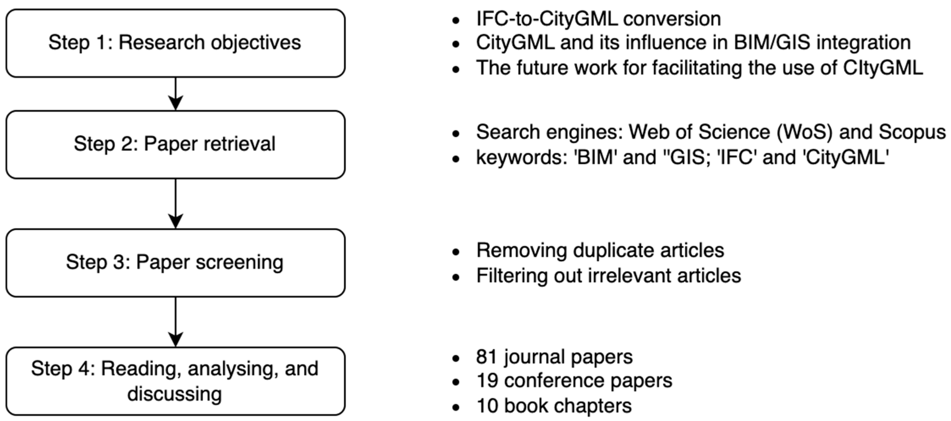
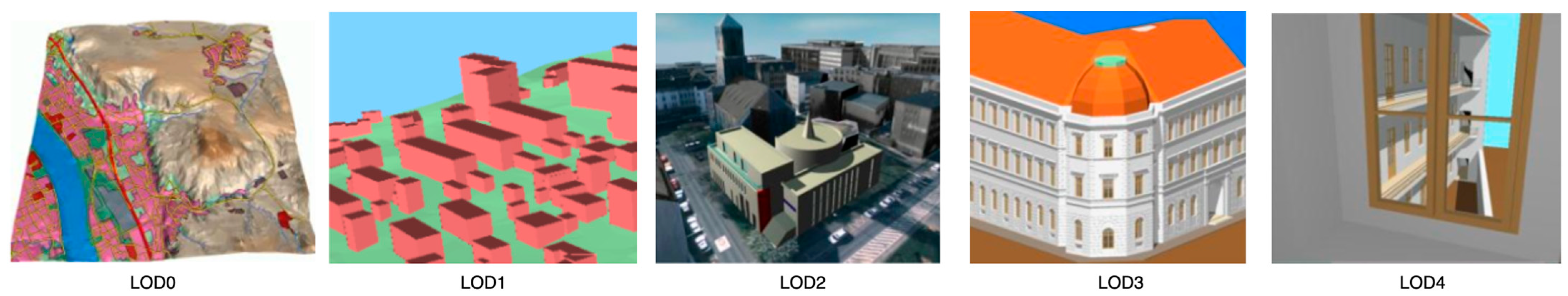
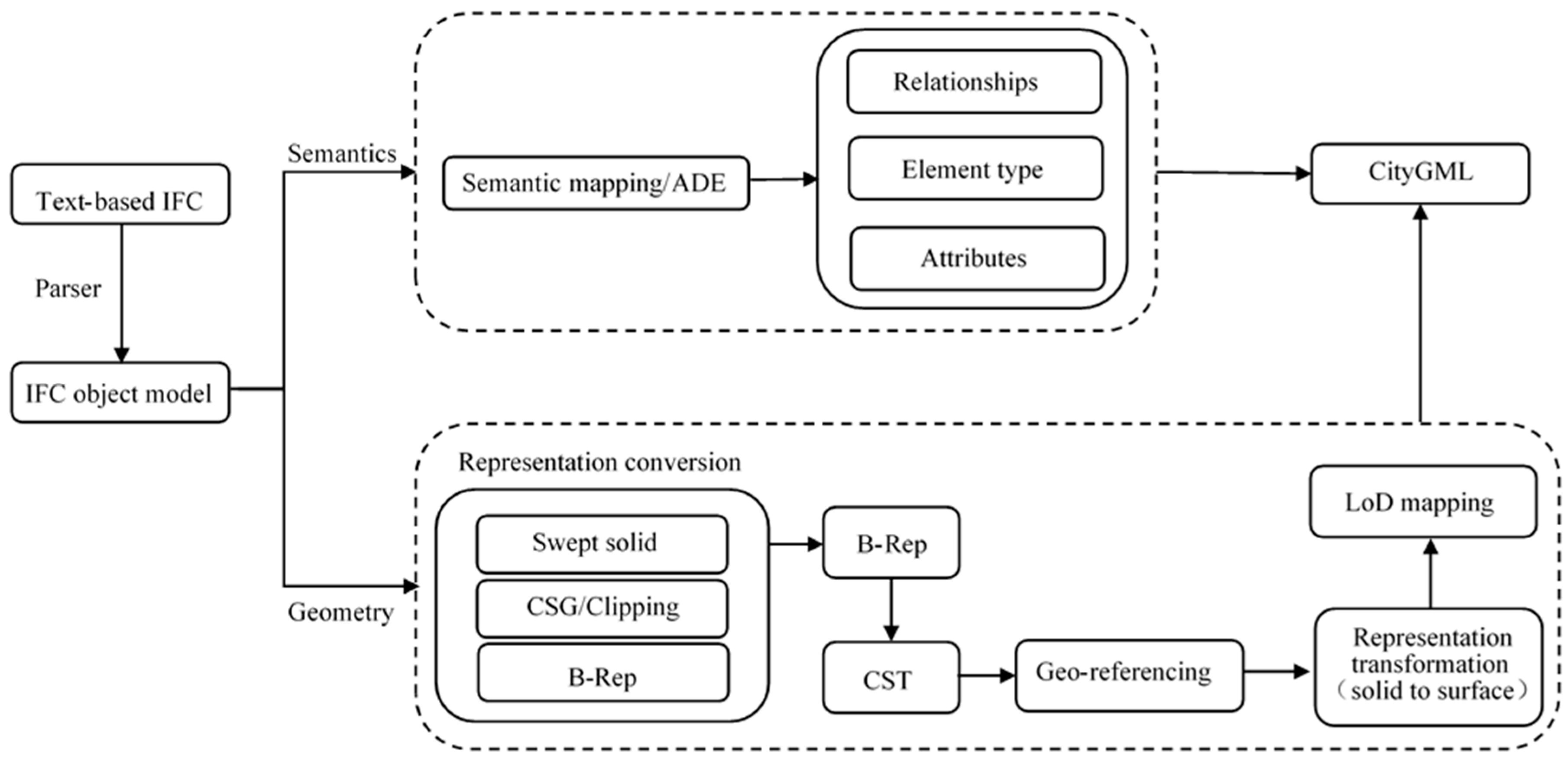
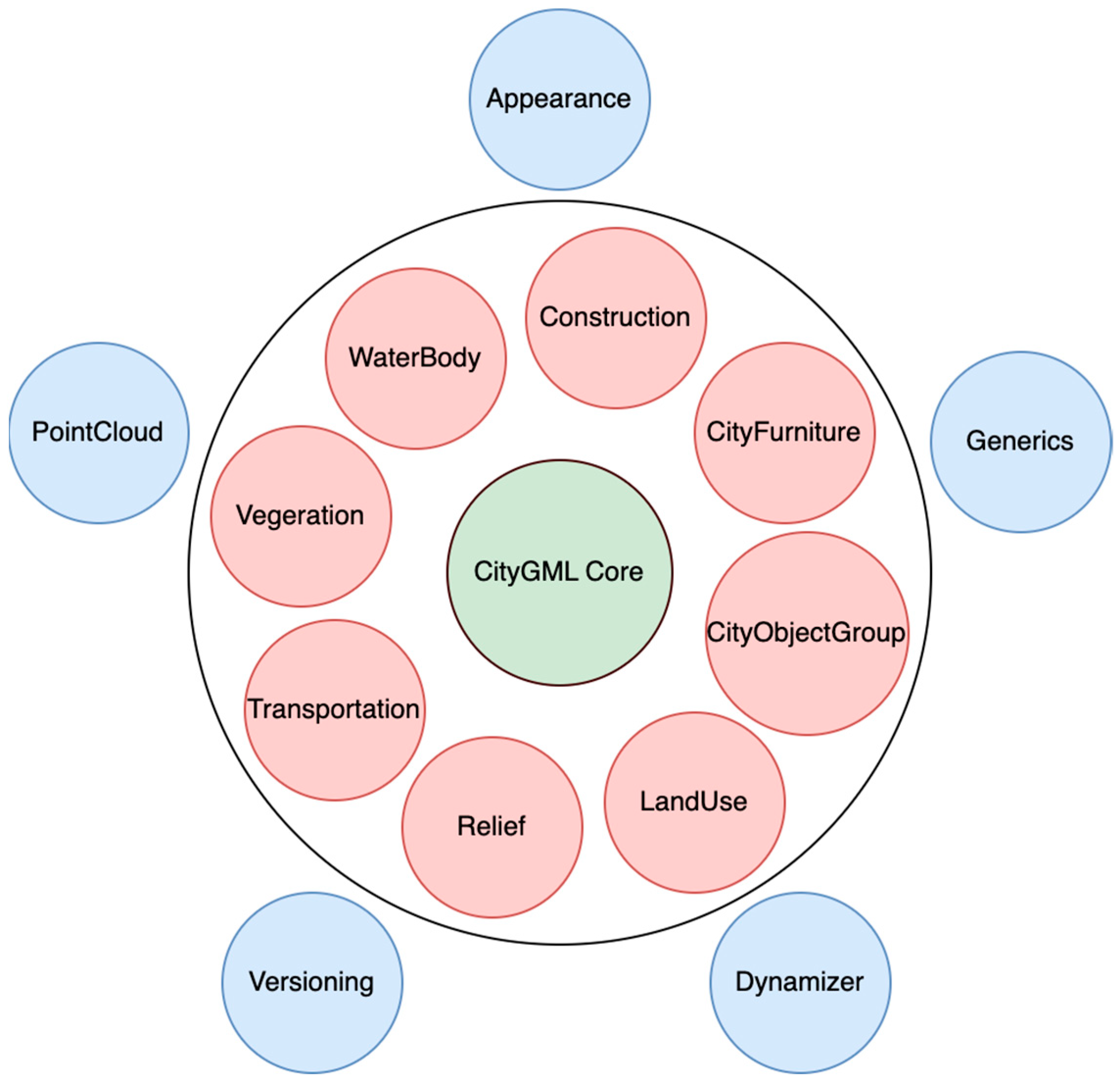
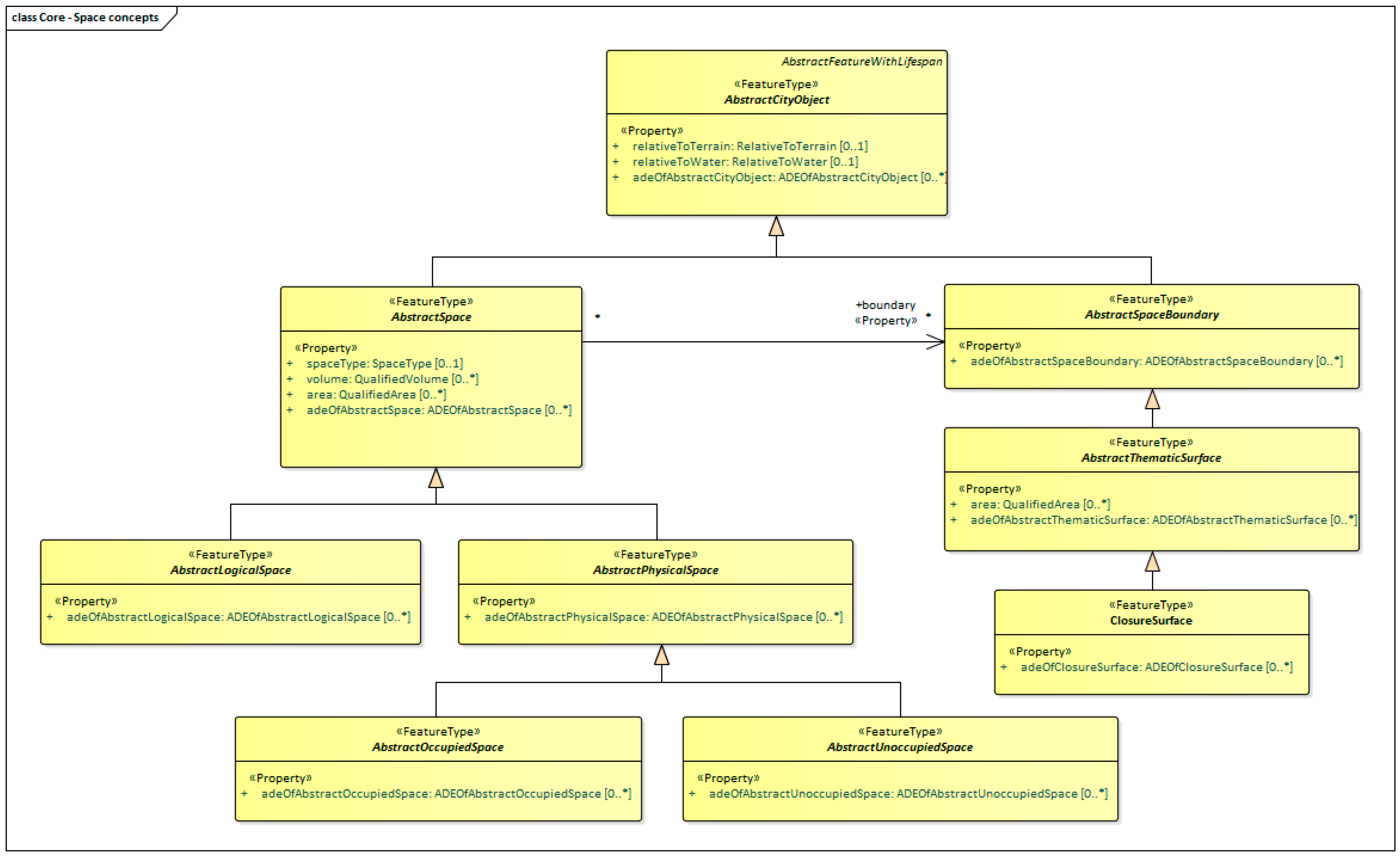
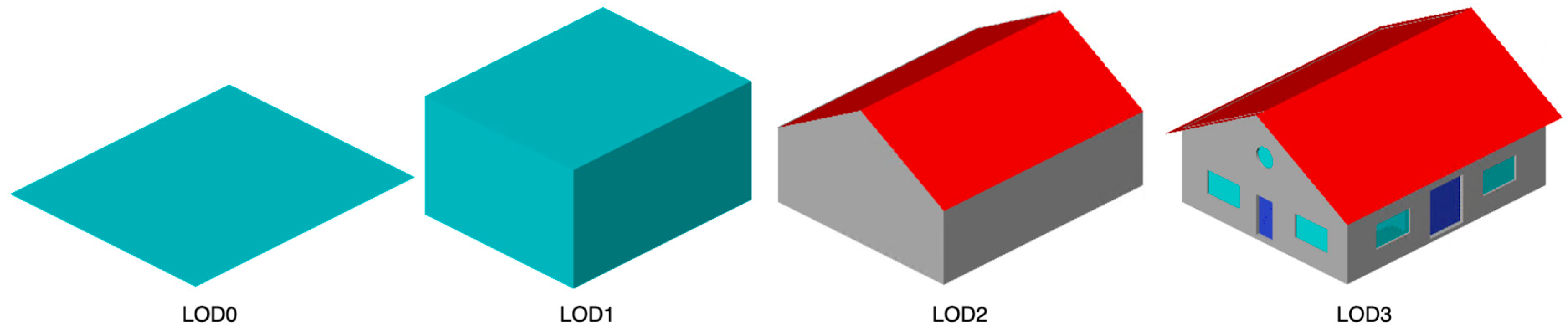
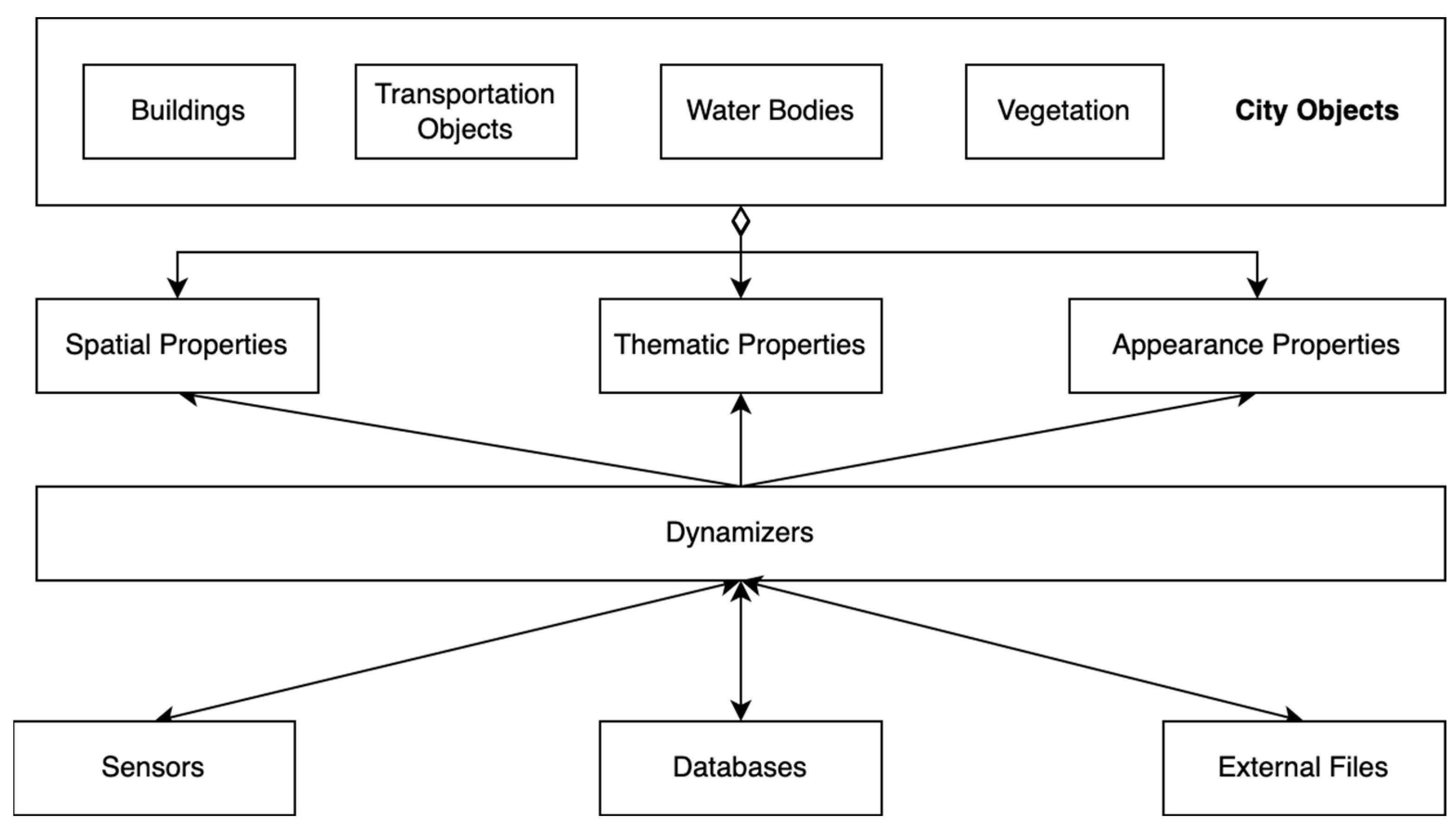


